

Investigating the Reliability and Dynamic Response of Fully 3D-Printed Thermistors


Abstract
1. Introduction
2. Materials and Methods
3. Results and Discussion
4. Conclusions
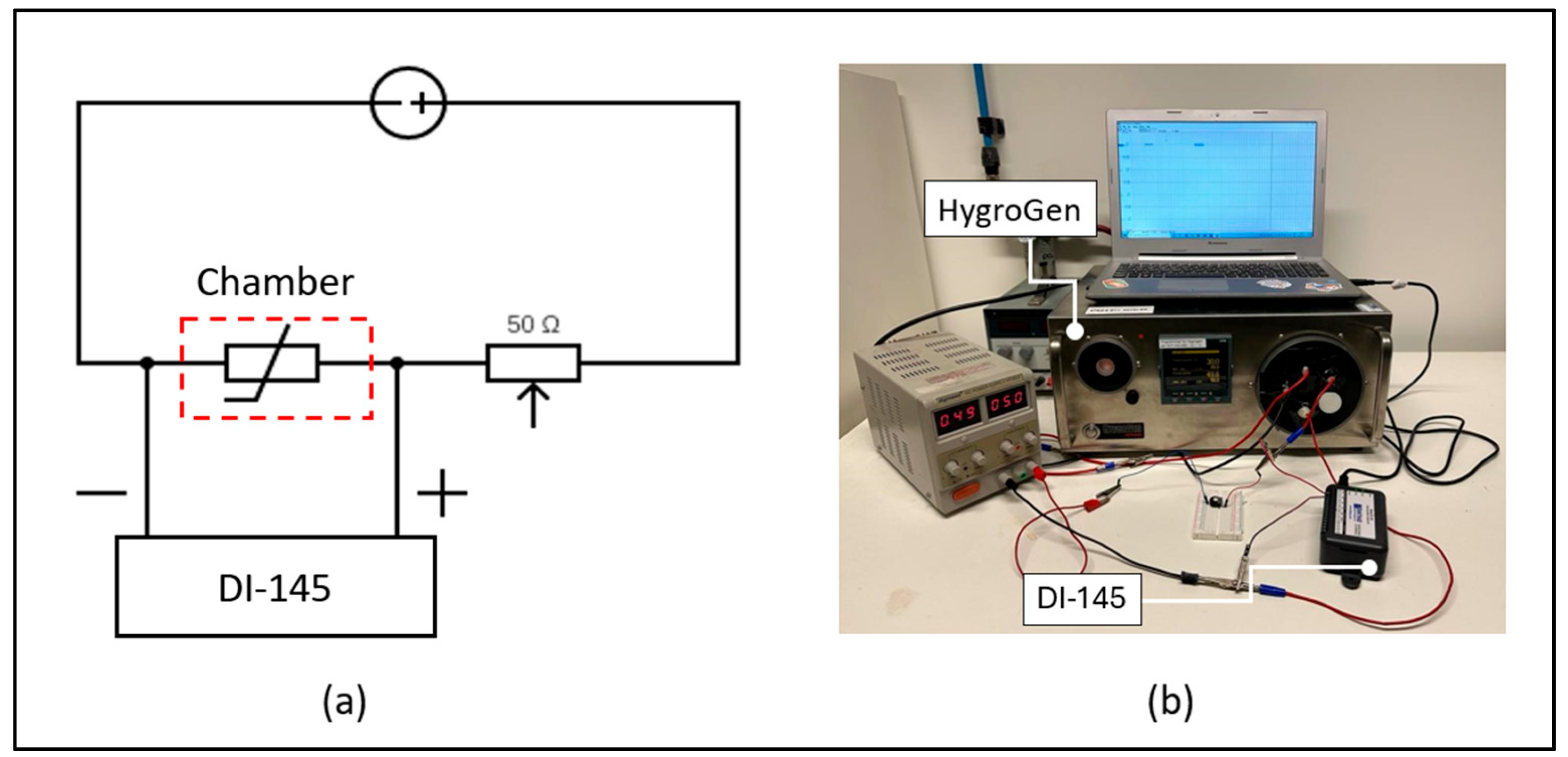
- The thermistors were characterized in terms of measurement capability, dynamic performance, and mechanical reliability over the temperature range of 25 to 45 °C.
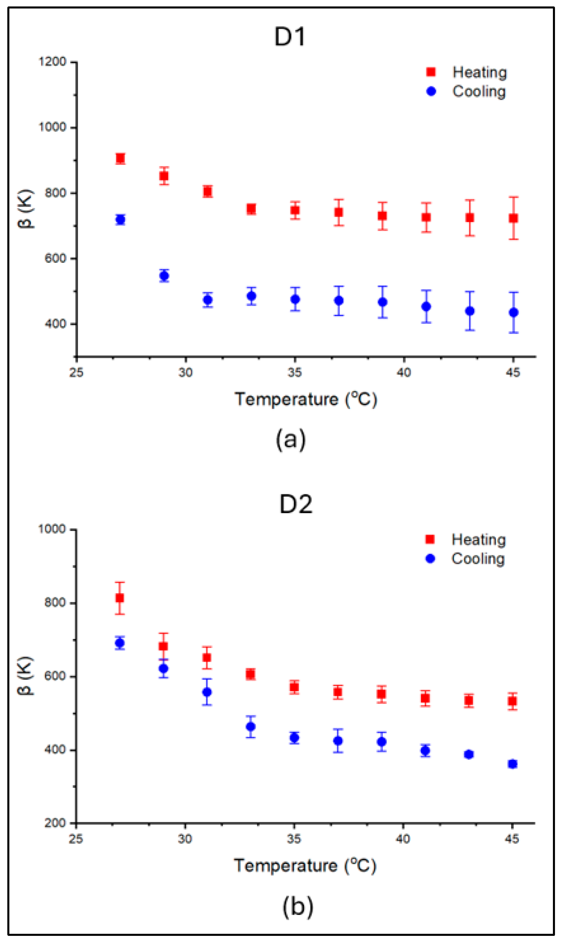
- The highest recorded thermal indexes were 905.64 K for D1 and 813.03 K for D2 thermistors, comparable to values reported in the literature.
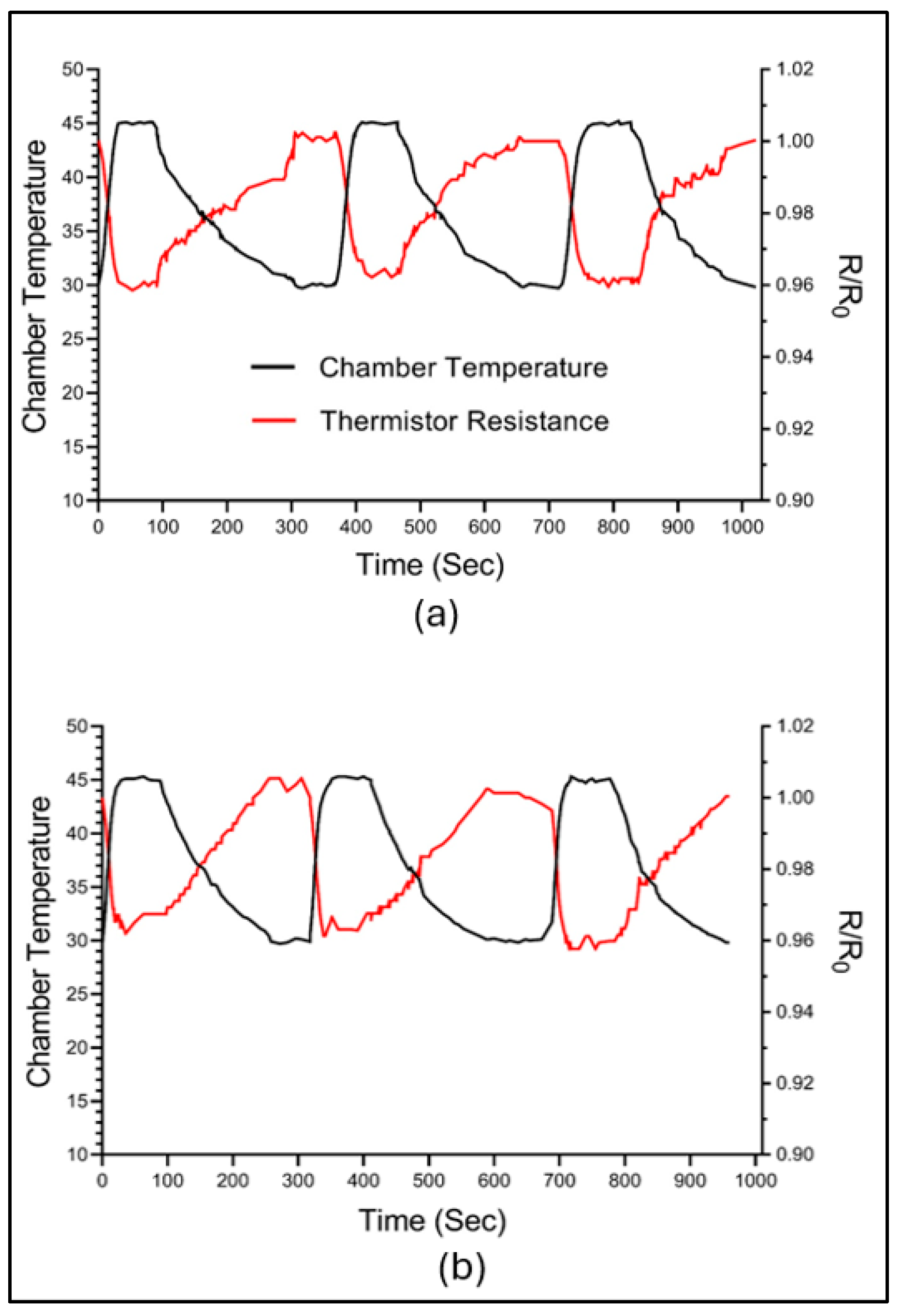
- Both designs showed similar dynamic performance, with the smaller sensing area of D2 providing quicker response times and faster relaxation.
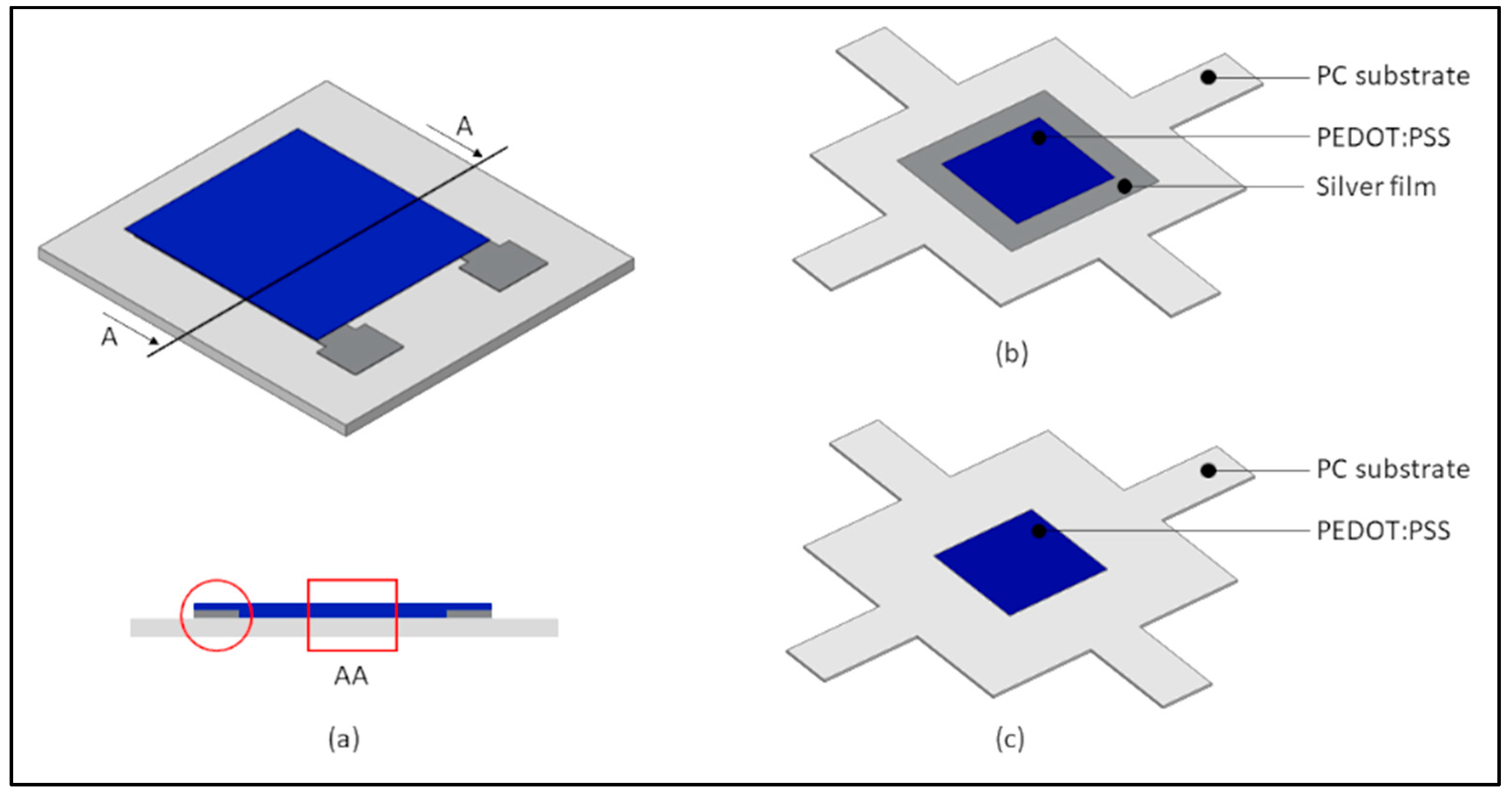
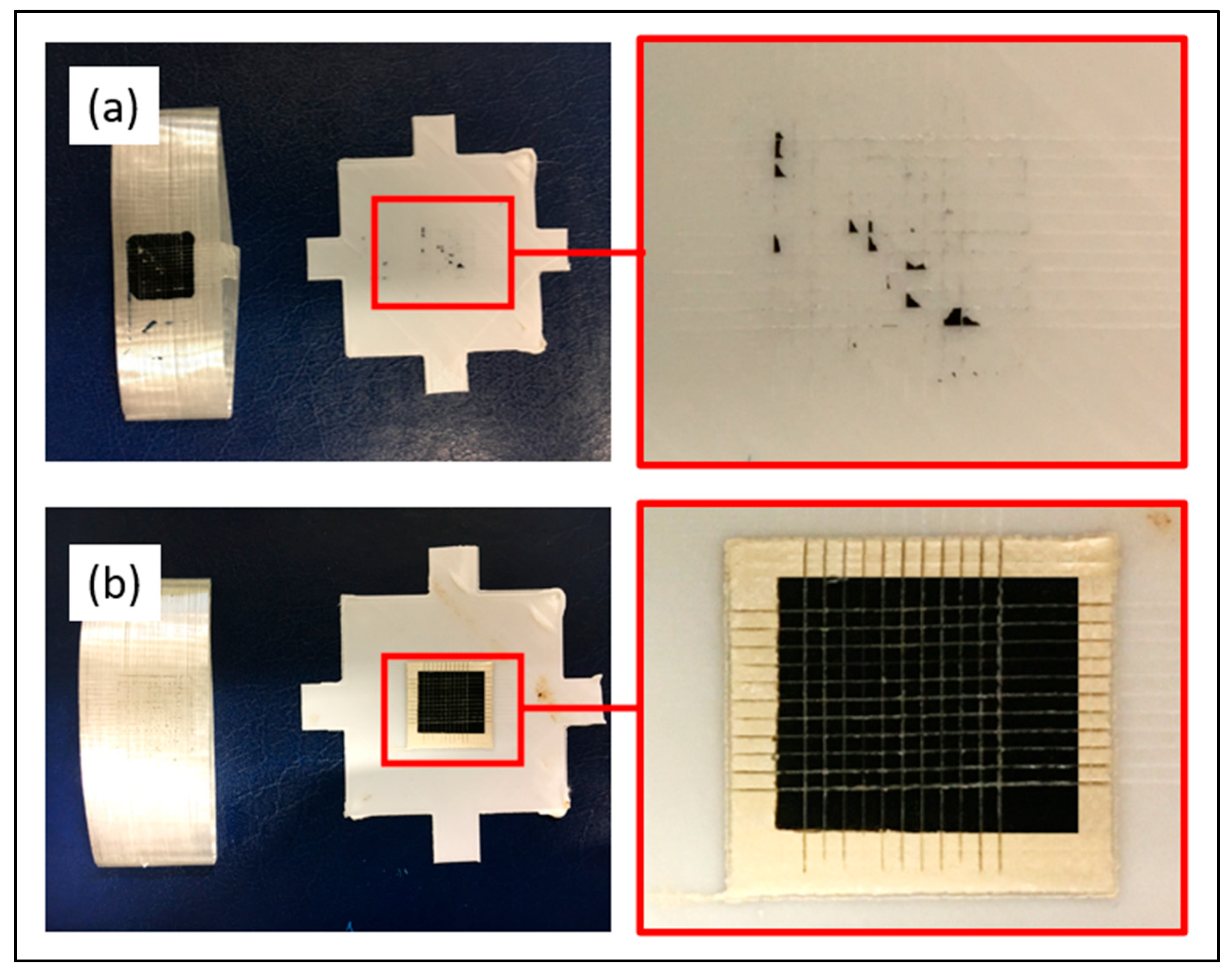
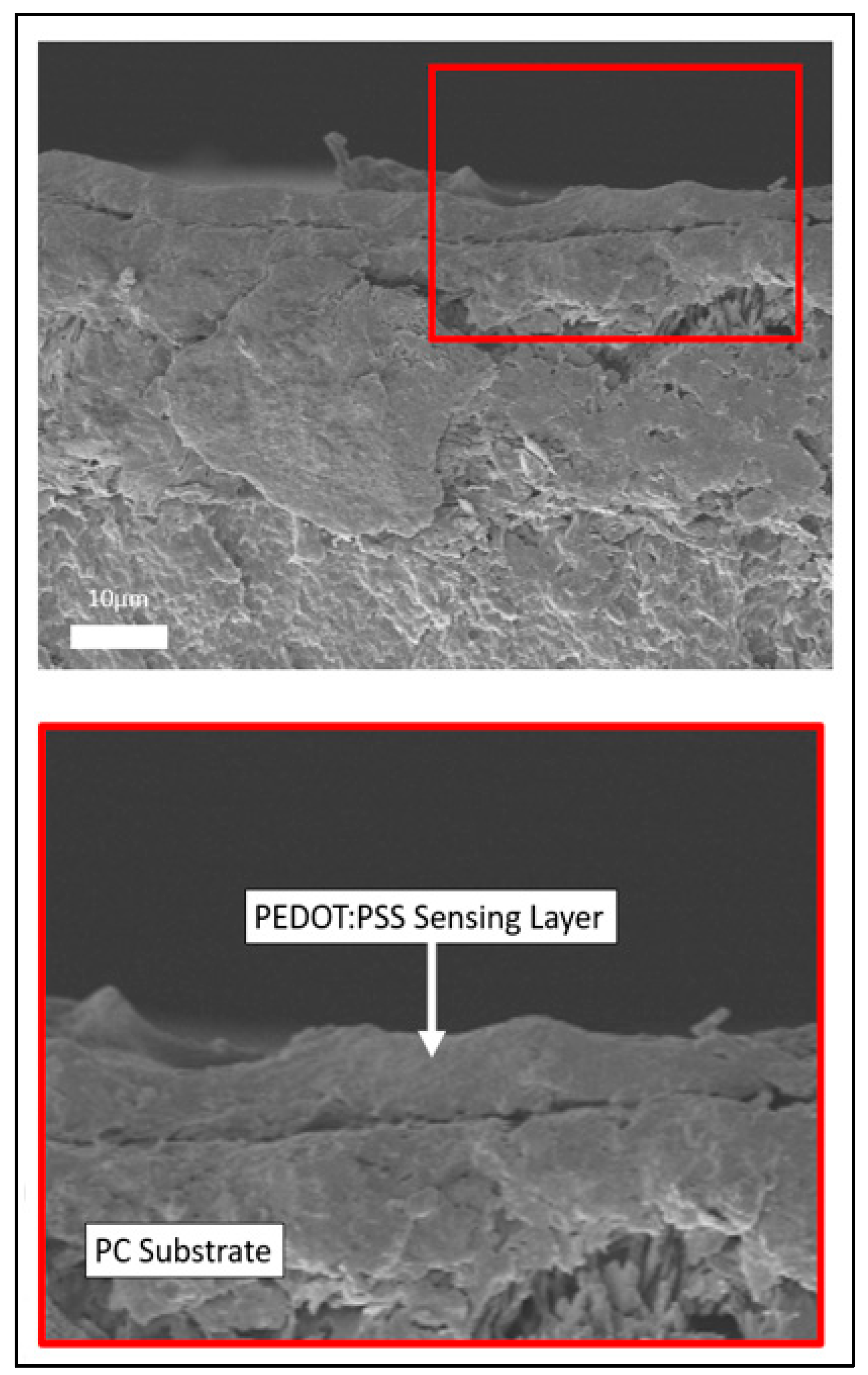
- Mechanical reliability was material-dependent: strong bonding was observed between PEDOT:PSS and the Ag layer, while weak adhesion with the PC substrate resulted in over 65% material removal.
Author Contributions
Funding
Institutional Review Board Statement
Informed Consent Statement
Data Availability Statement
Conflicts of Interest
Abbreviations
| AM | additive manufacturing |
| PE | printed electronics |
| FDM | fused deposition modeling |
| PEDOT:PSS | poly(3,4-ethylenedioxythophene):poly(4-styrenesulfonate) |
| Ag | silver |
| PC | polycarbonate |
| β | thermal index |
| SEM | scanning electron microscope |
| NTC | negative temperature coefficient |
References
- ASTM F2792-12; Standard Terminology for Additive Manufacturing Technologies, 12th ed. ASTM International: West Conshohocken, PA, USA, 2012.
- Blakey-Milner, B.; Gradl, P.; Snedden, G.; Brooks, M.; Pitot, J.; López, E.; Leary, M.; Berto, F.; Du Plessis, A. Metal Additive Manufacturing in Aerospace: A Review. Mater. Des. 2021, 209, 110008. [Google Scholar] [CrossRef]
- Paterson, A.M.; Donnison, E.; Bibb, R.J.; Campbell, R.I. Computer-aided design to support fabrication of wrist splints using 3D printing: A feasibility study. Hand Ther. 2014, 19, 102–113. [Google Scholar] [CrossRef]
- Han, D.; Lee, H. Recent advances in multi-material additive manufacturing: Methods and applications. Curr. Opin. Chem. Eng. 2020, 28, 158–166. [Google Scholar] [CrossRef]
- MacDonald, E.; Wicker, R. Multiprocess 3D printing for increasing component functionality. Science 2016, 353, aaf2093. [Google Scholar] [CrossRef]
- Perez, K.B.; Williams, C.B. Design Considerations for Hybridizing Additive Manufacturing and Direct Write Technologies. In Volume 4: 19th Design for Manufacturing and the Life Cycle Conference, Proceedings of the 8th International Conference on Micro-and Nanosystems, Buffalo, NY, USA, 17–20 August 2014; American Society of Mechanical Engineers: Buffalo, New York, NY, USA, 2014; pp. 1–12. [Google Scholar]
- Roach, D.J.; Hamel, C.M.; Dunn, C.K.; Johnson, M.V.; Kuang, X.; Qi, H.J. The m4 3D printer: A multi-material multi-method additive manufacturing platform for future 3D printed structures. Addit. Manuf. 2019, 29, 100819. [Google Scholar] [CrossRef]
- Cicek, U.I.; Southee, D.J.; Johnson, A.A. The development and characterisation of 3D-printed multi-material thermistor. Addit. Manuf. 2024, 94, 104510. [Google Scholar] [CrossRef]
- Cicek, U.I.; Southee, D.J.; Johnson, A.A. 2D characterisation and evaluation of multi-material structures towards 3D hybrid printing. Virtual Phys. Prototyp. 2023, 18, e2181193. [Google Scholar] [CrossRef]
- Kafle, A.; Luis, E.; Silwal, R.; Pan, H.M.; Shrestha, P.L.; Bastola, A.K. 3D/4D Printing of Polymers: Fused Deposition Modelling (FDM), Selective Laser Sintering (SLS), and Stereolithography (SLA). Polymers 2021, 13, 3101. [Google Scholar] [CrossRef]
- Ngo, T.D.; Kashani, A.; Imbalzano, G.; Nguyen, K.T.Q.; Hui, D. Additive Manufacturing (3D Printing): A Review of Materials, Methods, Applications and Challenges. Compos. Part B Eng. 2018, 143, 172–196. [Google Scholar] [CrossRef]
- Gibson, I.; Rosen, D.; Stucker, B.; Khorasani, M. Additive Manufacturing Technologies, 3rd ed.; Springer International Publishing: Cham, Switzerland, 2021. [Google Scholar]
- Espalin, D.; Muse, D.W.; MacDonald, E.; Wicker, R.B. 3D Printing multifunctionality: Structures with electronics. Int. J. Adv. Manuf. Technol. 2014, 72, 963–978. [Google Scholar] [CrossRef]
- Vogeler, F.; Verheecke, W.; Voet, A.; Valkenaers, H. An Initial Study of Aerosol Jet® Printed Interconnections on Extrusion-Based 3D-Printed Substrates. Stroj-Vestn.-J. Mech. Eng. 2013, 59, 689–696. [Google Scholar] [CrossRef]
- Carranza, G.T.; Robles, U.; Valle, C.L.; Gutierrez, J.J.; Rumpf, R.C. Design and Hybrid Additive Manufacturing of 3-D/Volumetric Electrical Circuits. IEEE Trans. Compon. Packag. Manuf. Technol. 2019, 9, 1176–1183. [Google Scholar] [CrossRef]
- Goh, G.L.; Agarwala, S.; Tan, H.K.J.; Zhao, L.; Chuah, T.K.; Yeong, W.Y. Additively manufactured multi-material free-form structure with printed electronics. Int. J. Adv. Manuf. Technol. 2017, 94, 1309–1316. [Google Scholar] [CrossRef]
- Nassar, H.; Dahiya, R. Fused Deposition Modeling-Based 3D-Printed Electrical Interconnects and Circuits. Adv. Intell. Syst. 2021, 3, 2100102. [Google Scholar] [CrossRef]
- Hong, F.; Tendera, L.; Myant, C.; Boyle, D. Vacuum-Formed 3D Printed Electronics: Fabrication of Thin, Rigid and Free-Form Interactive Surfaces. SN Comput. Sci. 2022, 3, 275. [Google Scholar] [CrossRef]
- Podsiadły, B.; Bezgan, L.; Słoma, M. 3D Printed Electronic Circuits from Fusible Alloys. Electronics 2022, 11, 3829. [Google Scholar] [CrossRef]
- Wałpuski, B.; Słoma, M. Additive Manufacturing of Electronics from Silver Nanopowders Sintered on 3D Printed Low-Temperature Substrates. Adv. Eng. Mater. 2021, 23, 2001085. [Google Scholar] [CrossRef]
- Hsiao, F.-R.; Liao, Y.-C. Printed Micro-Sens.for Simultaneous Temperature and Humidity Detection. IEEE Sens. J. 2018, 18, 6788–6793. [Google Scholar] [CrossRef]
- Khalaf, A.M.; Issa, H.H.; Ramirez, J.L.; Mohamed, S.A. All Inkjet-Printed Temperature Sens.Based on PEDOT: PSS. IEEE Access 2022, 10, 61094–61100. [Google Scholar] [CrossRef]
- Kuzubasoglu, B.A.; Bahadir, S.K. Flexible temperature sensors: A review. Sens. Actuators A Phys. 2020, 315, 112282. [Google Scholar] [CrossRef]
- Barmpakos, D.; Kaltsas, G. A Review on Humidity, Temperature and Strain Printed Sensors—Current Trends and Future Perspectives. Sensors 2021, 21, 739. [Google Scholar] [CrossRef] [PubMed]
- Shi, L.; Zhang, N.; Li, L.; Ding, S.; Li, W.; Li, K. Printed flexible temperature sensors: Principles, materials, processes, and applications. Appl. Mater. Today 2025, 43, 102665. [Google Scholar] [CrossRef]
- Khan, S.; Lorenzelli, L.; Dahiya, R.S. Technologies for Printing Sens.and Electronics Over Large Flexible Substrates: A Review. IEEE Sens. J. 2015, 15, 3164–3185. [Google Scholar] [CrossRef]
- Bücher, T.; Huber, R.; Eschenbaum, C.; Mertens, A.; Lemmer, U.; Amrouch, H. Printed temperature sensor array for high-resolution thermal mapping. Sci. Rep. 2022, 12, 14231. [Google Scholar] [CrossRef]
- Kwon, I.W.; Son, H.J.; Kim, W.Y.; Lee, Y.S.; Lee, H.C. Thermistor behavior of PEDOT: PSS thin film. Synth. Met. 2009, 159, 1174–1177. [Google Scholar] [CrossRef]
- Su, Y.; Ma, C.; Chen, J.; Wu, H.; Luo, W.; Peng, Y.; Luo, Z.; Li, L.; Tan, Y.; Omisore, O.M.; et al. Printable, Highly Sensitive Flexible Temperature Sens.for Human Body Temperature Monitoring: A Review. Nanoscale Res. Lett. 2020, 15, 1–34. [Google Scholar] [CrossRef]
- Khan, S.; Ali, S.; Khan, A.; Bermak, A. Wearable Printed Temperature Sensors: Short Review on Latest Advances for Biomedical Applications. IEEE Rev. Biomed. Eng. 2021, 16, 152–170. [Google Scholar] [CrossRef]
- Wei, Q.; Mukaida, M.; Kirihara, K.; Naitoh, Y.; Ishida, T. Recent Progress on PEDOT-Based Thermoelectric Materials. Materials 2015, 8, 732–750. [Google Scholar] [CrossRef]
- Štulík, J.; Polanský, R.; Hamáček, A.; Nešpůrek, S.; Slepička, P.; Kolská, Z.; Švorčík, V. Comparison of organic thermistors based on PEDOT: PSS and PEDOT:tos thin films under various thermal and humidity conditions. Sens. Actuators B Chem. 2018, 275, 359–366. [Google Scholar] [CrossRef]
- Maskey, B.B.; Shrestha, K.; Sun, J.; Park, H.; Park, J.; Parajuli, S.; Shrestha, S.; Jung, Y.; Ramasundaram, S.; Koirala, G.R.; et al. Proving the robustness of a PEDOT: PSS-based thermistor via functionalized graphene oxide–poly(vinylidene fluoride) composite encapsulation for food logistics. RSC Adv. 2020, 10, 12407–12414. [Google Scholar] [CrossRef]
- Khalaf, A.M.; Ramírez, J.L.; Mohamed, S.A.; Issa, H.H. Highly sensitive interdigitated thermistor based on PEDOT: PSS for human body temperature monitoring. Flex. Print. Electron. 2022, 7, 045012. [Google Scholar] [CrossRef]
- Soni, M.; Bhattacharjee, M.; Ntagios, M.; Dahiya, R. Printed Temperature Sensor Based on PEDOT: PSS-Graphene Oxide Composite. IEEE Sens. J. 2020, 20, 7525–7531. [Google Scholar] [CrossRef]
- Cicek, U.I.; Johnson, A.A. Multi-objective optimization of FDM process parameters for 3D-printed polycarbonate using Taguchi-based Gray Relational Analysis. Int. J. Adv. Manuf. Technol. 2025, 137, 3709–3725. [Google Scholar] [CrossRef]
- Kong, D.; Le, L.T.; Li, Y.; Zunino, J.L.; Lee, W. Temperature-Dependent Electrical Properties of Graphene Inkjet-Printed on Flexible Materials. Langmuir 2012, 28, 13467–13472. [Google Scholar] [CrossRef]
- Gleadall, A. FullControl GCode Designer: Open-source software for unconstrained design in additive manufacturing. Addit. Manuf. 2021, 46, 102109. [Google Scholar] [CrossRef]
- Kuzubasoglu, B.A.; Sayar, E.; Cochrane, C.; Koncar, V.; Bahadir, S.K. Wearable temperature sensor for human body temperature detection. J. Mater. Sci. Mater. Electron. 2021, 32, 4784–4797. [Google Scholar] [CrossRef]
- ASTM D3359-17; Standard Test Methods for Rating Adhesion by Tape Test. ASTM International: West Conshohocken, PA, USA, 2017.
- Hussain, M.M.; El-Atab, N. Handbook of Flexible and Stretchable Electronics; CRC Press: Boca Raton, FL, USA, 2019. [Google Scholar]
- Wu, S.; Hu, Z.; Jiang, N.; Zhai, J.; Liu, Y.; Wang, Z.; Kang, C.; Wang, Y. Flexible Temperature Sensor Array Based on PEDOT: PSS Inkjet Printing. IEEE Sens. J. 2024, 24, 22249–22258. [Google Scholar] [CrossRef]
- McGhee, J.; Sagu, J.; Southee, D.; Evans, P.; Wijayantha, K. Ferrite-based room temperature negative temperature coefficient printed thermistors. Electron. Lett. 2020, 56, 1322–1324. [Google Scholar] [CrossRef]
- Bahar, A.; Belhabib, S.; Guessasma, S.; Benmahiddine, F.; Hamami, A.E.A.; Belarbi, R. Mechanical and Thermal Properties of 3D Printed Polycarbonate. Energies 2022, 15, 3686. [Google Scholar] [CrossRef]
- Kuzubasoglu, B.A.; Sayar, E.; Bahadir, S.K. Inkjet-Printed CNT/PEDOT: PSS Temperature Sensor on a Textile Substrate for Wearable Intelligent Systems. IEEE Sens. J. 2021, 21, 13090–13097. [Google Scholar] [CrossRef]
- Fenoy, G.E.; Azzaroni, O.; Knoll, W.; Marmisollé, W.A. Functionalization Strategies of PEDOT and PEDOT: PSS Films for Organic Bioelectronics Applications. ChemoSens. 2021, 9, 212. [Google Scholar] [CrossRef]
- Carter, J.L.; Kelly, C.A.; Jenkins, M.J. Enhanced adhesion of PEDOT: PSS to substrates using polydopamine as a primer. Polym. J. 2023, 56, 115–120. [Google Scholar] [CrossRef]
- Inoue, A.; Yuk, H.; Lu, B.; Zhao, X. Strong adhesion of wet conducting polymers on diverse substrates. Sci. Adv. 2020, 6, eaay5394. [Google Scholar] [CrossRef] [PubMed]
- Zhang, X.; Yang, W.; Zhang, H.; Xie, M.; Duan, X. PEDOT: PSS: From conductive polymers to sensors. Nanotechnol. Precis. Eng. 2021, 4, 045004. [Google Scholar] [CrossRef]

| PC Substrate | ||||
|---|---|---|---|---|
| Property | Specific gravity | Melt mass-flow rate | Glass transition | Heat deflection |
| Unit | g/cm3 | g/min | °C | °C |
| Value | 1.18–1.20 | 2.30–2.60 | 107.70 | 104.50 ± 0.70 |
| Ag electrode | ||||
| Property | Viscosity | Sheet resistance | Specific gravity | Solid content |
| Unit | Pa.s | mΩ/sq | g/cm3 | % |
| Value | 7.00–10.00 | 25.00–85.00 | 1.996 | 55.69–57.69 |
| PEDOT:PSS layer | ||||
| Property | Viscosity | Resistance | Concentration | Appearance |
| Unit | Pa.s | Ω/sq | % | Color |
| Value | ≥50.00 | ≤130.00 | 5.00 wt | Dark to very dark blue and black |
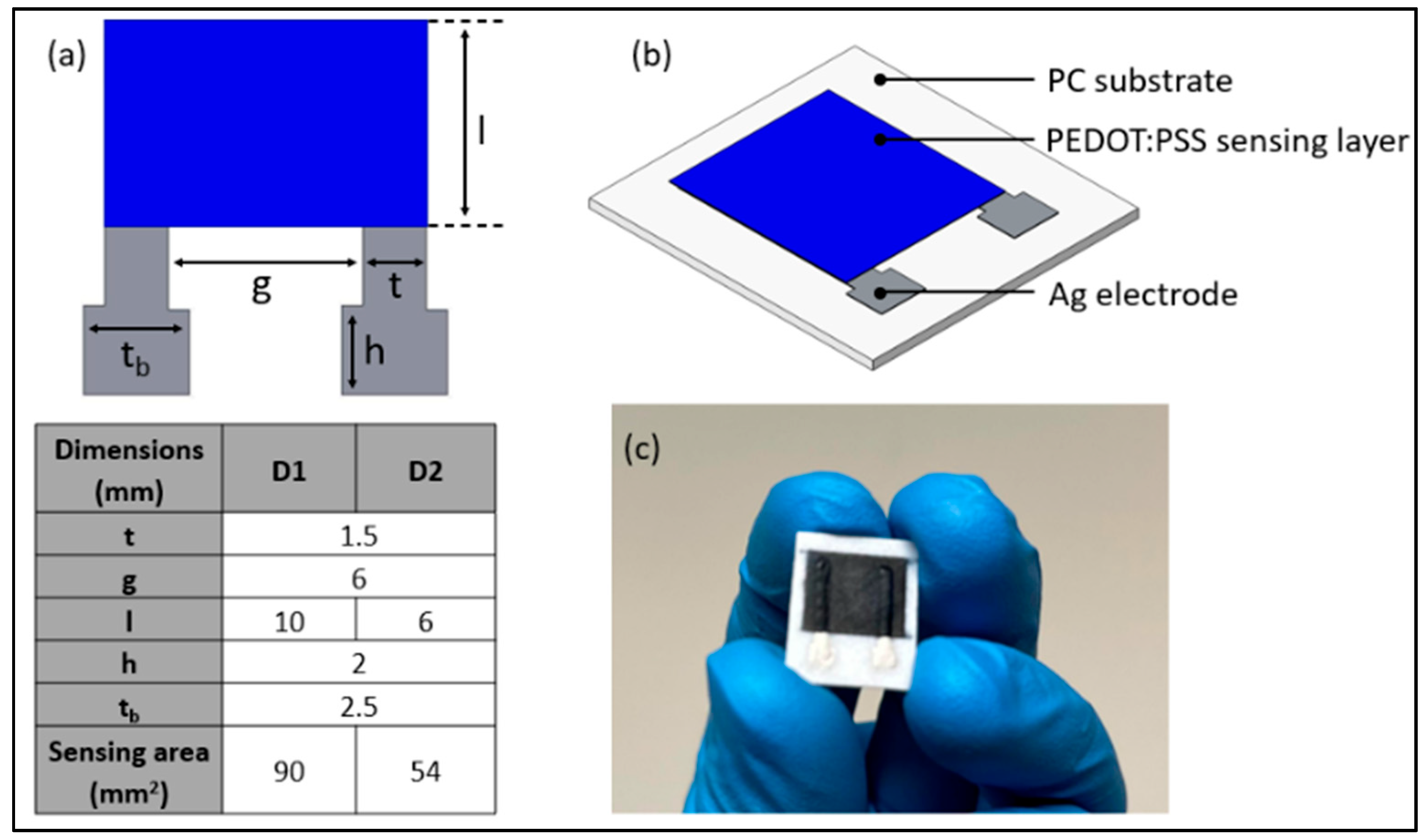
| Parameter | Unit | PC Substrate | Ag Electrode | PEDOT:PSS Layer |
|---|---|---|---|---|
| Thickness | [µm] | 500 | 50 | 50 |
| Layer thickness | [mm] | 0.05 | 0.05 | 0.05 |
| Nozzle diameter | [mm] | 0.4 | 0.2 | 0.2 |
| Dispensing width | [mm] | 0.04 | 0.15 | 0.15 |
| Print speed | [mm/s] | 20 | 30 | 25 |
| Nozzle temperature | [°C] | 275 | - | - |
| Curing temperature | [°C] | - | 100 (for 2 h) | 80 (for 1 h) |
| Temperature Range | D1 | D2 | ||
|---|---|---|---|---|
| Heating | Cooling | Heating | Cooling | |
| 25–27 | 905.64 ± 16.20 | 719.48 ± 14.75 | 813.03 ± 44.00 | 691.60 ± 17.40 |
| 27–29 | 852.28 ± 26.04 | 588.02 ± 18.42 | 681.69 ± 37.00 | 621.96 ± 24.90 |
| 29–31 | 805.49 ± 16.87 | 474.26 ± 22.19 | 651.05 ± 30.50 | 557.60 ± 35.70 |
| 31–33 | 771.36 ± 15.42 | 485.90 ± 26.03 | 606.15 ± 14.64 | 463.43 ± 29.27 |
| 33–35 | 747.56 ± 25.57 | 476.26 ± 35.54 | 570.75 ± 17.80 | 433.44 ± 15.13 |
| 35–37 | 741.44 ± 39.96 | 472.04 ± 44.59 | 557.22 ± 18.26 | 425.12 ± 31.35 |
| 37–39 | 730.16 ± 42.46 | 467.65 ± 48.75 | 551.69 ± 22.27 | 422.16 ± 26.12 |
| 39–41 | 725.61 ± 44.76 | 453.59 ± 49.27 | 540.33 ± 21.62 | 398.49 ± 16.15 |
| 41–43 | 724.61 ± 54.76 | 440.08 ± 59.49 | 533.45 ± 17.58 | 387.80 ± 7.64 |
| 43–45 | 723.74 ± 65.08 | 435.89 ± 62.24 | 532.44 ± 22.57 | 361.67 ± 8.70 |
| Temperature Range | D1 | D2 | ||
|---|---|---|---|---|
| Heating | Cooling | Heating | Cooling | |
| 27–29 | 6.26 | 24.47 | 19.27 | 11.20 |
| 29–31 | 5.81 | 21.88 | 4.71 | 13.08 |
| 31–33 | 4.43 | 2.39 | 7.41 | 16.28 |
| 33–35 | 3.18 | 2.02 | 6.20 | 9.13 |
| 35–37 | 0.83 | 0.89 | 2.43 | 1.96 |
| 37–39 | 1.54 | 0.94 | 1.00 | 0.70 |
| 39–41 | 0.63 | 3.10 | 2.10 | 5.94 |
| 41–43 | 0.14 | 3.07 | 1.29 | 2.76 |
| 43–45 | 0.12 | 0.96 | 0.19 | 4.22 |
Disclaimer/Publisher’s Note: The statements, opinions and data contained in all publications are solely those of the individual author(s) and contributor(s) and not of MDPI and/or the editor(s). MDPI and/or the editor(s) disclaim responsibility for any injury to people or property resulting from any ideas, methods, instructions or products referred to in the content. |
© 2025 by the authors. Licensee MDPI, Basel, Switzerland. This article is an open access article distributed under the terms and conditions of the Creative Commons Attribution (CC BY) license (https://creativecommons.org/licenses/by/4.0/).
Share and Cite
Cicek, U.; Southee, D.; Johnson, A. Investigating the Reliability and Dynamic Response of Fully 3D-Printed Thermistors. Appl. Sci. 2025, 15, 6822. https://doi.org/10.3390/app15126822
Cicek U, Southee D, Johnson A. Investigating the Reliability and Dynamic Response of Fully 3D-Printed Thermistors. Applied Sciences. 2025; 15(12):6822. https://doi.org/10.3390/app15126822
Chicago/Turabian StyleCicek, Umur, Darren Southee, and Andrew Johnson. 2025. "Investigating the Reliability and Dynamic Response of Fully 3D-Printed Thermistors" Applied Sciences 15, no. 12: 6822. https://doi.org/10.3390/app15126822
APA StyleCicek, U., Southee, D., & Johnson, A. (2025). Investigating the Reliability and Dynamic Response of Fully 3D-Printed Thermistors. Applied Sciences, 15(12), 6822. https://doi.org/10.3390/app15126822