1. Introduction
In sports activities, the use of wearable devices has a significant impact on providing reliable feedback to users. Undoubtedly, the most dependable information concerns time measurement, as it is independent of the user’s movement or the placement of the wearable device. However, with current technological advancements, a product that solely measures time is no longer attractive in the market. The demand for multifunctionality is significantly higher now than it was a decade ago. Users expect their wearable devices to perform various tasks beyond timekeeping, such as counting laps, steps, strokes, and stairs, monitoring heart rate, interacting with user interfaces, enabling GPS localization, displaying smartphone notifications, or even processing payments.
Focusing on motion monitoring, most wearable devices available on the market provide feedback data but not real-time feedback during movement. One such commercially available system is the Cometa Wave, which includes inertial sensors capable of rapid and accurate data acquisition, real-time communication with external devices, and onboard flash memory for offline data storage. The system supports integration of up to 36 IMU and EMG sensors, enabling full-body motion analysis [
1].
Research using the Cometa Wave system (Cometa Systems, Inc., Newburg, MO, USA) in swimming applications typically involves recording data in the device memory, followed by offline analysis to better understand aquatic motion patterns [
2,
3]. As this system currently lacks a direct competitor offering similar features, it is priced at a premium, with configurations costing several thousand euros depending on the number of devices used [
4].
Although the Cometa system provides reliable IMU data, it lacks real-time feedback for swimmers during performance. This limitation is critical, as swimmers are unable to assess the quality of their strokes while in the water. Movement verification is only possible post-session using a desktop application that downloads and analyzes the stored sensor data.
This paper proposes an improved approach for monitoring human movement in water using ESP32 microcontrollers (Espressif Systems, Shanghai, China) and MPU6050 accelerometer and gyroscope sensors (TDK InvenSense, San Jose, CA, USA). The system employs a pattern recognition algorithm based on Dynamic Time Warping (DTW) to evaluate each swimming stroke [
5]. After each attempt, the system informs the swimmer whether the stroke was performed correctly, based on pre-recorded reference patterns stored on the device. A vibration motor provides immediate vibrational alert by activating briefly when a stroke does not match the expected movement pattern.
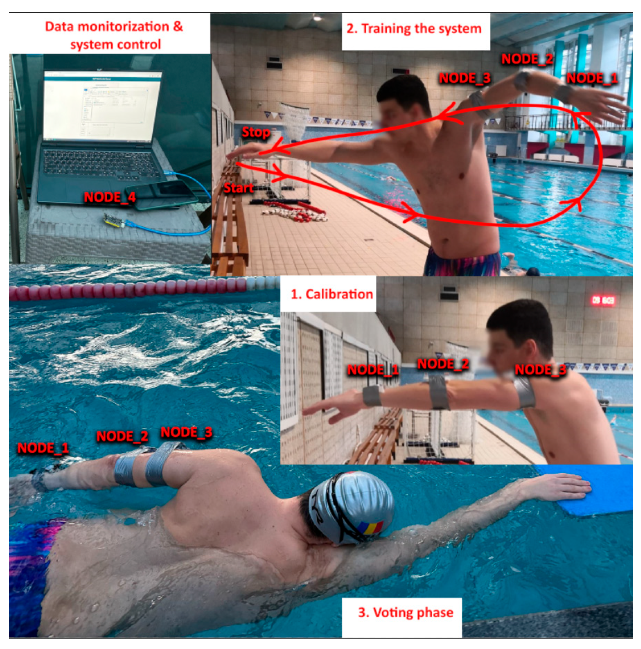
For this study, three monitoring devices were placed on the left arm—at the wrist, elbow, and shoulder. Each device, comprising an ESP32, an MPU6050 and a 500 mA LiPo battery, costs approximately 30 euros, resulting in a total system cost of about 90 euros.
2. Materials and Methods
Studies involving real-time guidance of human movement during activities are relatively rare [
6,
7]. This paper proposes a novel approach for delivering live feedback in aquatic environments.
The hardware utilized in this study was previously tested on dry land, as presented in the work titled “Learning Swimming Techniques by Means of Real-Time Monitoring with Embedded Devices” [
8]. For the current study, the system was enhanced with a vibration motor integrated into each device and was modified for waterproof operation to enable use in water-based testing.
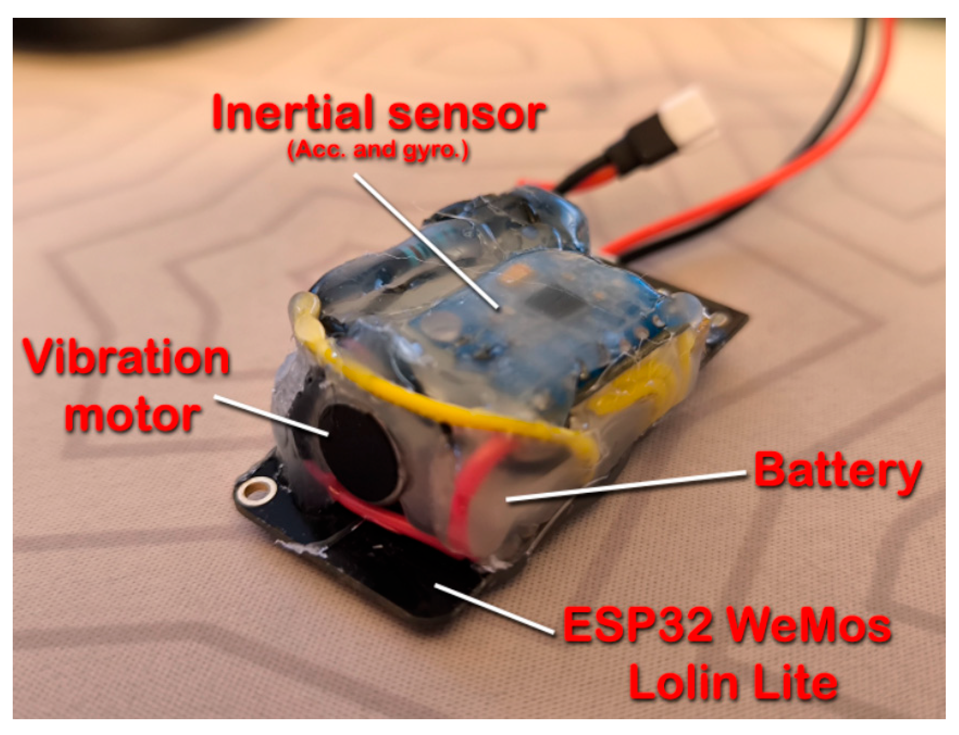
The vibration motor employed is the Disc Vibration Motor 1027 (Shenzhen ChuangXinDa Micro Motor Co., Shenzhen, China),which is connected to an output pin of the ESP32 Lolin Lite microcontroller (Espressif Systems, Shanghai, China). This setup allows the motor to be activated or deactivated as needed, providing vibration-based (tactile) feedback to the user when specific movement triggers are detected.
A vibration motor is well-suited for this type of feedback, due to its ability to deliver precise tactile feedback at specific locations on the skin, allowing the user to identify the exact point of error through direct skin contact [
9]. Given the aquatic environment, vibration feedback remains effective, as it is perceptible even underwater. In contrast, using an acoustic buzzer [
10] as an alternative feedback modality would require a sound level high enough for the user to hear, which could disturb other swimmers during training sessions due to its audibility in the surrounding area. Moreover, with multiple devices operating simultaneously, acoustic feedback may introduce ambiguity, making it difficult for the user to discern which specific body part is not moving correctly, based on the received feedback from the devices. An alternative method for providing feedback is through the use of smart goggles, which can visually display information directly to the swimmer [
11,
12].
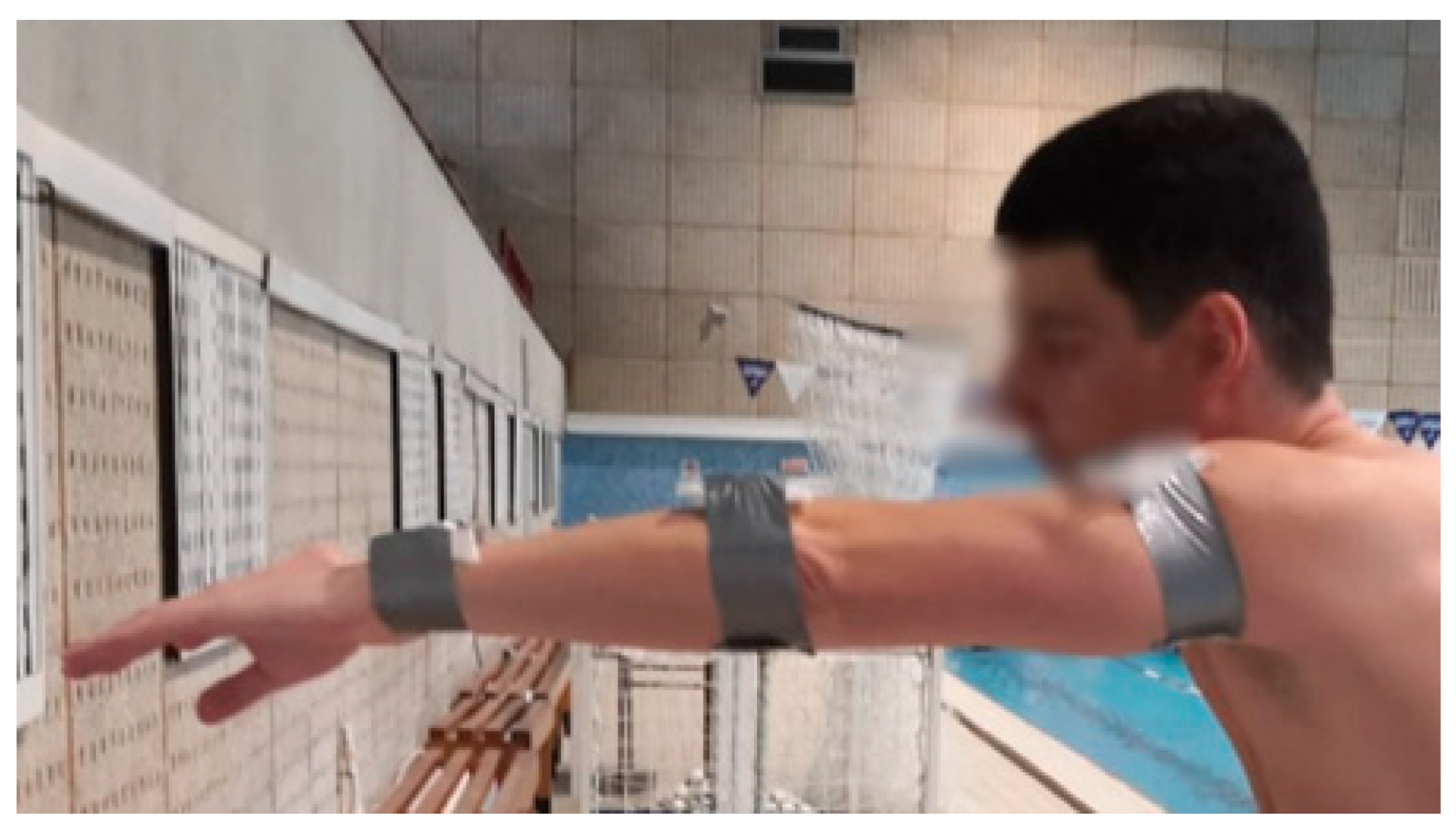
To achieve waterproofing, hot glue was applied to seal the device, with careful attention to leave access to the battery socket for charging and the programming interface. As a result, the device is not fully waterproof. Therefore, it was enclosed in a resealable plastic bag, which was sealed before placement on the user’s arm [
13]. The updated device is present in
Figure 1 below.
Alternative waterproofing methods were also explored. These included the use of waterproof cases designed for action cameras and waterproof smartphone pouches, both of which offer sealed enclosures to protect the electronics from water ingress.
Using the enclosures shown in
Figure 1, it was necessary to apply additional tape inside the cases to stabilize the device. Without this, the device tended to shift during gesture execution. In contrast, the plastic bags shown in
Figure 2 molds closely to the device, securing it firmly to the arm. In both configurations, strong waterproof duct tape was employed to maintain the device in the desired position on the arm [
14].
An ideal enclosure consists of a custom-designed waterproof case, which can be fabricated using 3D printing. However, as the prototype is still under continuous development, including hardware modifications, premature acquisition of a prefabricated solid enclosure would increase costs. Once the enclosure design is finalized, it can incorporate straps similar to those used in other wearables, such as smartwatches, thereby eliminating the need for temporary solutions like duct tape.
As a software side, the system keeps in majority the implementation from “Learning Swimming Techniques by Means of Real-Time Monitoring with Embedded Devices” paper. What is new is the reading of gyroscope values, the direct output feedback to the user with activating the vibration motor, synchronizing the user LED from the ESP32 to turn on every time the system reads data that is computed afterwards with the DTW algorithm and saving the trained mean of values in the non-volatile memory in order to have it after reset.
2.1. Reading
Sensor data are read by slave-type devices: Node_1, Node_2, and Node_3. The MPU6050 sensor provides measurements of both acceleration and gyroscopic rotation (angular velocity).
For the initial testing phase, only acceleration data along the X, Y, and Z axes were utilized. This approach was chosen to establish the core system functionality, which integrates all essential components. Consequently, it was more practical to validate three data streams (acceleration) rather than six (acceleration and rotation). A library for the MPU6050 sensor was used, which by default applies the most sensitive configuration settings (~0.000061 g, with 1 g ≈ 9.81 m/s2). These settings were retained for this project, with the accelerometer configured to a ±2 g range, yielding a data range of −32,768 to 32,768 for each axis (using int16 representation). This configuration was achieved by setting the AFS_SEL register to 0 × 00.
Similarly, the default configuration was used for the gyroscope, offering the highest sensitivity (~0.00763 °/s). This was configured by writing the value 0 × 00 to the GYRO_CONFIG register [
15].
The MPU6050 sensor was selected due to its combination of characteristics well-suited to the requirements of the implemented system. These include its integrated 3-axis gyroscope and 3-axis accelerometer, low power consumption, compact form factor, and widespread availability.
The power consumption values presented in
Table 1 are derived from the respective sensor datasheets and reflect typical active-mode current under standard operating conditions. It should be noted that actual power consumption may vary depending on sensor configuration, sampling rates, and specific usage scenarios.
The estimated read time per sample was calculated by dividing the number of data bytes to be read by the communication protocol’s data transfer speed.
The MPU6050 sensor was selected due to its advantageous combination of features, including integrated accelerometer and gyroscope, which sufficiently meet the requirements of this study. Its power consumption is negligible for the intended application, and the accuracy is adequate given the relatively simple motion patterns and sampling rates involved. Additionally, the sensor’s wide availability and low cost facilitate testing, enabling the use of multiple units with necessary soldering and connection points.
A comparative analysis of several commonly used motion tracking sensors is presented in
Table 1 to justify this choice:
2.2. Communication
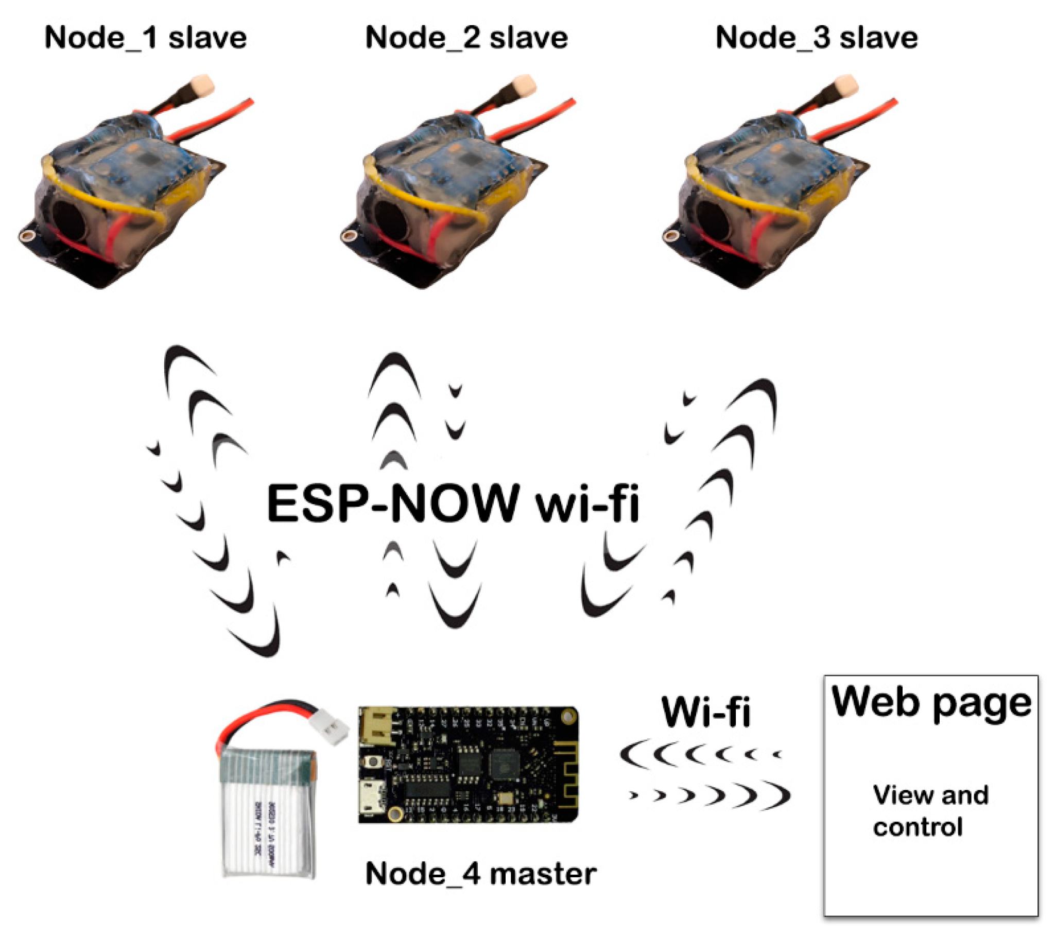
The core contribution of this work consists of the integration of the ESP-NOW protocol into the application system. This protocol enables comprehensive communication functionalities within the application, ranging from control data transmission and visualization data exchange to inter-node communication for context-aware data sharing, as well as debugging via Wi-Fi messages.
ESP-NOW employs a peer-to-peer communication model, enabling ESP devices to send and receive data directly, independent of external network infrastructure. In
Figure 4, an overview of the system is presented.
By combining the ESP-NOW protocol with the ESP32 Lolin Lite microcontroller and the MPU6050 sensor, the system supports real-time data acquisition and transmission. Efficient communication between devices is critical for ensuring low-latency data exchange and minimizing power consumption. Developed by Espressif Systems, ESP-NOW is a protocol that facilitates data exchange between ESP32 microcontrollers without requiring an active Wi-Fi connection or router. It is particularly suited for applications where low power consumption and rapid communication are essential, such as Internet of Things (IoT) systems, sensor networks, and smart devices [
16].
2.3. Computing and Data Transmission
In
Figure 5 below, illustrated are the steps in how the system is used.
The MPU6050 motion sensor returns raw data in a 16-bit signed integer format, with values ranging from −32,768 to 32,767. In the context of this project, the data are normalized by dividing these values, resulting in a reduced range approximately between −2 and 2, expressed in floating-point format. By dividing the raw values by 16,384, the resulting normalized interval of [−2, 2] corresponds to the default full-scale range of ±2 g in the MPU6050 sensor configuration.
However, ESP-NOW, the wireless communication protocol used for data transmission, is optimized for sending unsigned integer values and does not natively support the direct transmission of floating-point numbers. To address this limitation, a conversion strategy is implemented to enable the transfer of floating-point data between devices.
Two custom functions—encode_float and decode_float—are developed for this purpose. On the slave devices, where sensor data are acquired, the encode_float function converts floating-point values into integer representations suitable for ESP-NOW transmission. On the master device, the corresponding decode_float function receives these encoded values, unpacks the data, and accurately reconstructs the original floating-point values with up to five decimal places of precision.
The ESP-NOW protocol limits data transmission to 250 bytes per frame. Therefore, the transmitting-receiving system was adapted accordingly. At this stage, the transmission of consecutive frames to send multiple datasets is not required. Data acquired from the MPU6050 sensor consist of floating-point values representing 120 samples for each of the X (40), Y (40), and Z (40) axes of both the accelerometer and gyroscope. Each set of 120 values is packaged into a single frame for transmission via the ESP-NOW protocol. In addition to sensor data, four extra bytes are sent from the slave to the master device, representing the node ID, calibration state, training status, and movement votes.
Since a standard float occupies 4 bytes, transmitting raw float data would require approximately 484 bytes per frame, exceeding the ESP-NOW frame size limit. Moreover, the utilized library supports only unsigned data. To address this, float values are encoded into 2-byte unsigned integers before transmission and subsequently decoded back to float on the master device. This encoding-decoding process restricts float precision to approximately five decimal places. This limitation does not affect system accuracy, as five-decimal precision is sufficient for the application. Additionally, because the integer part of the DTW cost has a more significant influence on similarity comparison, minor variations in the decimal part have minimal impact on overall similarity evaluation.
To determine whether the movement performed during the voting phase corresponds to the intended motion, a comparison between the sensor-acquired data and the target motion pattern is required. For this purpose, the Dynamic Time Warping (DTW) algorithm is employed [
17].
Dynamic Time Warping (DTW) is a robust algorithm widely used to measure the similarity between two temporal sequences that may differ in length or speed. It is a fundamental technique in time-series analysis, with applications in domains such as speech recognition, gesture detection, motion sequence analysis, and signal processing. DTW is particularly valuable for comparing sequences that are not perfectly aligned in time, as it can accommodate temporal distortions and variability in data patterns [
18,
19].
The algorithm operates by constructing a cost matrix that quantifies the distance between each pair of elements from the two sequences. Each entry in the matrix represents the local distance between corresponding data points. DTW then identifies the optimal alignment path through this matrix—one that minimizes the cumulative distance—thus providing a similarity measure that is resilient to temporal shifts and speed variations.
To facilitate data verification and visualization, all relevant information is transmitted to the master node (Node_4) via Wi-fi. Each slave node sends the following types of data:
The complete set of accelerometer and gyroscope values recorded during each iteration of the training phase;
The averaged motion profile computed at the end of the training phase;
All accelerometer and gyroscope values collected during each recognized voting movement, along with the similarity percentage calculated by the Dynamic Time Warping (DTW) algorithm.
2.4. Calibration
2.4.1. Request
The calibration routine is invoked on demand, typically when it is necessary to redefine the system’s reference frame based on new origin points corresponding to acceleration (X, Y, Z) and rotation (X, Y, Z) axes [
20].
When calibration is requested by the master node, the slave node calls a dedicated function and continuously executes the corresponding code without interruption until the routine completes. Specifically, the MPU6050 motion sensor is used to acquire acceleration and rotational data along all three axes (X, Y, Z) at intervals of 50 ms, over 30 iterations. The total calibration duration is 1.5 s. The readings from each axis are accumulated in a buffer, and upon completion, the sum for each axis is averaged by dividing by the number of iterations (30). This process yields six calibration values, one for each axis.
These calibration values are subsequently incorporated into future readings during the learning and voting routines, enhancing measurement accuracy.
2.4.2. Automatic
Additionally, the system includes an automatic calibration mechanism, which updates the stored calibration values for each axis in real time.
To address CPU latency issues and ensure efficient management of the system’s control logic, a function called ‘stationary’ was implemented. This function continuously reads all six sensor values—acceleration and rotation along the X, Y, and Z axes—from the motion sensor. Each of these values is stored in a dedicated variable, preserving the last known reading for comparison with subsequent measurements.
The stationary function determines whether any of the six current sensor readings deviate from their respective previous values by more than 0.10. If such a deviation is detected, the function returns a boolean TRUE, signaling that the current readings should be included in the recalibration process.
The recalibration procedure is triggered conditionally, based on the stationary function’s output, and consists of 25 new readings acquired at 50-ms intervals. For each permitted iteration, the system collects acceleration and rotational data along all axes, computes the mean of these 25 samples, and uses the result to update the main calibration vector. Importantly, this update does not overwrite the existing calibration values; instead, the new averaged values are added to or subtracted from the existing entries in the calibration vector.
Ultimately, the updated calibration vector is incorporated into subsequent real-time sensor readings, thereby improving the system’s accuracy and adaptability over time.
2.5. Training Request
To enable accurate monitoring of specific motion patterns, a learning routine is implemented, which relies on repeated sampling of the target movement sequence. This routine is initiated by the master node and continues until 10 complete iterations of data acquisition are performed.
Once activated, the routine enters a continuous loop running at the microcontroller’s operating frequency, monitoring for variations in motion across all axes. Upon detecting movement, the system validates the condition for data recording and begins acquiring readings from the motion sensor. Sensor data—acceleration and rotation along the X, Y, and Z axes—are sampled every 50 ms. Each iteration consists of 40 readings, resulting in a 2 s data capture window per iteration. Given that each reading includes six parameters (three for acceleration and three for rotation), a total of 240 values are collected per iteration (40 × 6 = 240).
To account for potential inconsistencies or execution errors in individual motion sequences, the learning process is repeated across ten iterations, resulting in the storage of 2400 values per slave node. Since the routine is executed in parallel across three nodes, the complete system captures a total of 7200 data points during the learning phase.
At the end of the routine, the values from all iterations are aggregated element-wise across vectors and averaged to produce a representative template of the target motion. This averaged motion profile is then used in the voting routine for real-time comparison with incoming sensor data. Averaging reduces the impact of anomalies such as spikes or sudden deviations in sensor readings, thus improving pattern recognition reliability.
Finally, the resulting average values are stored in non-volatile memory, allowing the learned motion pattern to persist through system resets or when repeated learning is not desired.
This routine can be repeated multiple times until the mean set of values shows no significant deviations across the 10 executed repetitions. Visualization of the received data can be performed by plotting it using data from the master device. The training phase should be conducted under the supervision of a professional coach to validate all recorded movements.
2.6. Vote Request
For the voting process to be executed, the system requires that either the learning routine has been previously completed or that a motion template is already stored in non-volatile memory.
Data acquisition is performed from slave-type nodes. The system implementation is designed to manage data reading in a way that avoids executing verification algorithms on every reading cycle. Not all data values retrieved from the sensors are considered eligible for evaluation.
When entering the evaluation phase (referred to as the voting routine), the system aims to assess the movement attempted by the user. Performing verification at every acquisition step would reduce system performance. In the current implementation, sensor data are sampled every 50 ms. Each sample contains acceleration and rotational values along all three axes, resulting in a total of 240 values per sample. The Dynamic Time Warping (DTW) algorithm is applied to evaluate the similarity of the recorded movement to a reference pattern. The execution time for DTW on the current dataset is approximately 8.5 ms, which is relatively low. However, future improvements aim to increase the sampling frequency, which would, in turn, increase the computational load and execution time of the DTW algorithm [
21,
22,
23].
The voting routine is initiated by the master node and executed on the slave node. Once invoked, it runs continuously until either the execution mode changes or the system is powered down. The initial condition-checking phase resembles that of the learning routine; specific criteria must be met for the sensor data acquisition to begin.
Sensor readings are sampled every 50 ms and processed through both the stationery and motion detection functions. If no significant difference is detected between successive readings over 25 iterations, the system performs an origin recalibration by averaging these 25 values. However, if significant variation is observed, the system bypasses the stationary check and proceeds to motion detection.
Based on live measurements conducted under stationary conditions, the drift in the readable sensor data was not significant enough to noticeably affect the system’s output similarity.
To prevent unwanted measurements including gyroscope drift data, the stationary detection and recalibration functions continuously update the calibration dataset. This ongoing process helps maintain system stability and ensures reliable monitoring. Gyroscope data contribute to approximately 50% of the calculated similarity metric, with the remaining contribution derived from accelerometer data. Therefore, minor drift in the sensor’s output does not significantly influence the overall similarity result.
The motion detection logic verifies whether substantial movement is present on any of the six axes (acceleration and rotation on X, Y, Z). If movement is detected consistently over 10 consecutive samples, the system continues collecting an additional 30 samples, resulting in a complete set of 40 readings during active motion.
Upon reaching motion validation, the voting algorithm is triggered. This algorithm utilizes Dynamic Time Warping (DTW) to compare the captured motion sequence with the previously learned template. The DTW algorithm computes a similarity score, returning a percentage value that quantifies the degree of correspondence between the observed motion and the stored reference pattern.
The total time from the initiation of a movement to the completion of the similarity computation is approximately 2.10 s. This duration accounts for the acquisition of 40 sensor readings, captured at 50-ms intervals, resulting in a total collection time of 2 s per movement cycle. Following data acquisition, the Dynamic Time Warping (DTW) algorithm is executed locally on each slave node to compute the cost matrices and similarity score, a process that requires approximately 8.5 ms. Each slave node independently performs its DTW computation and provides immediate haptic feedback to the user via a vibration motor upon completing the similarity analysis.
Simultaneously, the computed results are transmitted to a master node over Wi-Fi. This transmission is conducted in parallel and is intended primarily for debugging and visualization purposes. The inter-device communication, implemented using the ESP-NOW protocol, introduces a transmission delay of less than 50 ms. The master node subsequently formats the received data as JSON and pushes it to a client browser using WebSocket technology. This enables near real-time display, with client-side parsing and rendering contributing negligible additional delay. The overall system architecture ensures timely feedback for the user while supporting efficient remote monitoring. In this configuration, the total time elapsed from the initiation of the movement to its visualization on the display is approximately 2.60 ms.
2.7. Similarity Computing
In order to find the desired formula to calculate a percentage for the style of the application, multiple testing and verification were performed based on the values returned by the Dynamic Time Warping (DTW) algorithm for each individual axis: axdtw, aydtw, azdtw, gxdtw, gydtw, and gzdtw. Various formulas were applied to compute the similarity percentage, using the DTW values specific to each axis. The use of a linear calculation—summing all DTW values and dividing by six—proved to be too permissive, resulting in high similarity scores even for movements with large deviations from the pattern. Introducing additional threshold restrictions provided some improvement; however, it required excessive verifications to achieve satisfactory results, increasing code complexity. By applying an exponential function, the similarity curve can be shaped more precisely, allowing the similarity values to be constrained and the sensitivity to be adjusted accordingly.
The final formula used for calculating the overall
similarity percentage is as follows:
where
dtw_total represents the sum of the six DTW output values corresponding to the three acceleration (axdtw, aydtw, azdtw) and three rotation (gxdtw, gydtw, and gzdtw) axes. This expression was selected based on empirical tuning to balance sensitivity and robustness in the matching process [
24].
If the
similarity percentage obtained at the end of the voting phase falls below the threshold of 70%, the vibration motor is activated for 200 ms. This haptic feedback informs the user that the movement detected at the corresponding node on the arm does not sufficiently match the stored reference pattern [
25,
26].
2.8. LED Indication on Testing Phase
A valuable feature for debugging and testing purposes is the implementation of a visual trigger using the onboard user LED of the ESP32 microcontroller. The LED is activated each time the system reads data that is classified as valid for further processing—i.e., data that successfully pass the movement verification logic during either the training or evaluation (voting) phase.
The blue LED serves as a simple and effective visual indicator, allowing observers to confirm, in real time, that the system is correctly identifying and processing meaningful motion events. Importantly, the LED remains visible through waterproof enclosures such as sealed plastic bags or waterproof cases, making it especially useful during in-water testing scenarios.
Once triggered, the LED remains illuminated until the movement ceases or the voting routine is executed to determine whether the performed motion matches the expected pattern.
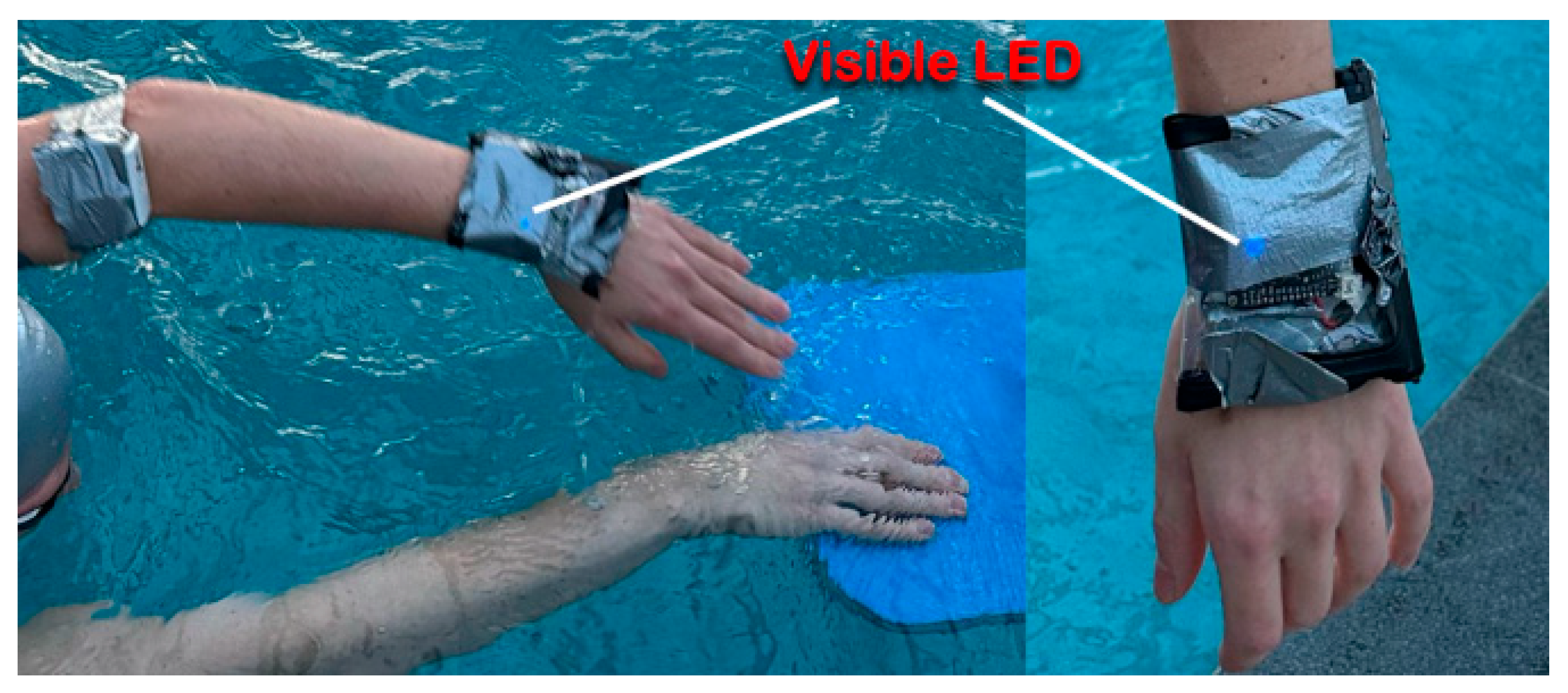
Figure 6 demonstrates the visibility of the LED indicator through the duct tape covering. The light remains perceptible even underwater and can be detected by the user’s peripheral vision during swimming.
2.9. Battery Consumption
The estimated battery life during continuous operation, as calculated in the previous study [
8], is approximately 3.24 h.
To enable real-time feedback, the system integrates a vibration component using a Disc Vibration Motor 1027, which is activated for 200 ms whenever an incorrect movement is detected. This motor typically consumes approximately 80 mA during operation (at 3 V power source). The additional power consumption varies based on the frequency of incorrect movements, which directly affects how often the motor is triggered.
Three usage scenarios were considered for power consumption analysis:
- (1)
Frequent errors: The motor is triggered every 2 s (mistake at every attempt), resulting in 1800 activations per hour. With each activation lasting 0.2 s, the total activation time per hour is 360 s. This adds approximately 8 mAh to the hourly power consumption, increasing the total current draw to 162 mA and reducing the estimated battery life to approximately 3.09 h.
- (2)
Moderate errors: The motor is triggered every 6 s (1 from 3 attempts is a mistake), resulting in 600 activations per hour. This adds approximately 2.66 mAh to the hourly power consumption, increasing the total current draw to 156.6 mA and reducing the estimated battery life to approximately 3.19 h.
- (3)
Rare errors: The motor is triggered every 2 min (30 activations/h), adding just 0.14 mAh per hour to the consumption. The overall current draw becomes 154.14 mA, and battery life remains essentially unchanged at approximately 3.24 h.
The above results were made with the following formulas:
These results indicate that the inclusion of a vibration motor for real-time feedback has a negligible effect on power consumption under typical usage conditions [
27,
28,
29]. Only in scenarios with very frequent feedback activation does the impact on battery life become noticeable. This confirms that the system remains suitable for extended testing and training sessions, while still providing meaningful real-time correction to the user.
A typical swimming training session lasts between 1 and 3 h, depending on the swimmer’s level. Since not all training time is dedicated to technique improvement exercises, the actual usage duration of the system during a session is reduced. In this context, the estimated battery life of approximately 3.24 h per charge is sufficient to support one full training session per day, after which the system can be recharged.
To extend battery life further, several improvements are recommended: replacing the sensor with a low-power alternative (BMI270), utilizing a controller with enhanced low-power features, limiting Wi-Fi communication during the voting phase or increasing battery capacity. Implementing these enhancements would enable the system to operate across multiple training sessions before requiring a full recharge.
3. Results
The swimming style employed in this study is front crawl, performed with the assistance of a polyester kickboard. The use of the board enables isolation of upper or lower limb movements, facilitating a more controlled and sequential execution. This approach ensures consistent data acquisition, allowing for systematic analysis and accurate documentation of the motion patterns. This approach ensured that stroke execution followed a sequential pattern, similar to well-established technique drills commonly practiced by swimmers. In each repetition, the swimmer’s hand returned to the same starting position—at the water’s surface—allowing reliable wireless data transmission from the slave devices attached to the swimmer to the master device.
This surface-level hand position is crucial for communication, as Wi-Fi transmission from submerged slave nodes is unreliable, and data sent while underwater is typically not received by the master device. However, this limitation does not affect the real-time feedback provided to the swimmer, since the vibration motor feedback is locally executed by the slave device immediately after computation. The wireless data transmission is currently intended for debugging and visualization purposes only.
Future developments may focus on enhancing the system’s communication protocols and hardware design to better support swimmers of varying skill levels and training intensities, particularly those requiring continuous underwater feedback.
All testing of the system was performed on a single subject who was 30 years old and 193 cm tall, with an arm span of 203 cm.
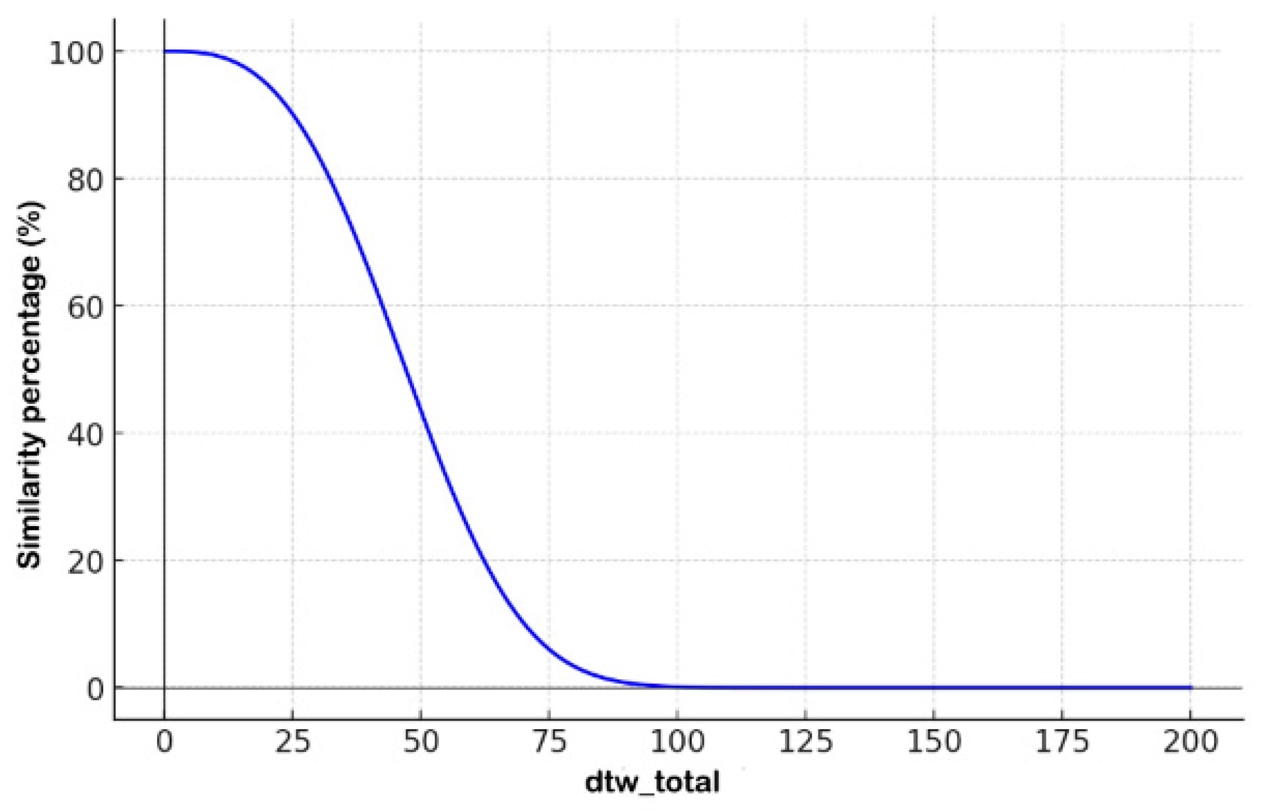
As defined by the
similarity percentage formula in Equation (1),
Figure 7 presents a plot of the resulting
similarity percentage as a function of the total Dynamic Time Warping (DTW) distance. The system exhibits high sensitivity to the cumulative DTW values (
dtw_total) obtained from all six axes. When the sum of the DTW values remains below 25, the calculated
similarity percentage stays within a high confidence range of 90% to 100%. However, once the
dtw_total exceeds 25, the system begins to penalize the similarity output more significantly.
A steep decline in similarity is observed as dtw_total increases from 30 to 70, with the similarity percentage dropping from approximately 80% to as low as 15%. For dtw_total values exceeding 80, the system effectively classifies the movement as dissimilar, assigning a near-zero similarity score.
The similarity function was designed and tuned during dryland testing to offer high discrimination with minimal interference from environmental factors. However, this calibration presents challenges in aquatic environments, where variables such as water resistance, whole-body motion (influencing gyroscope data), and forward swimmer velocity can introduce noise and variability into the acceleration data. These factors may degrade the accuracy of similarity evaluation when the system is used in water.
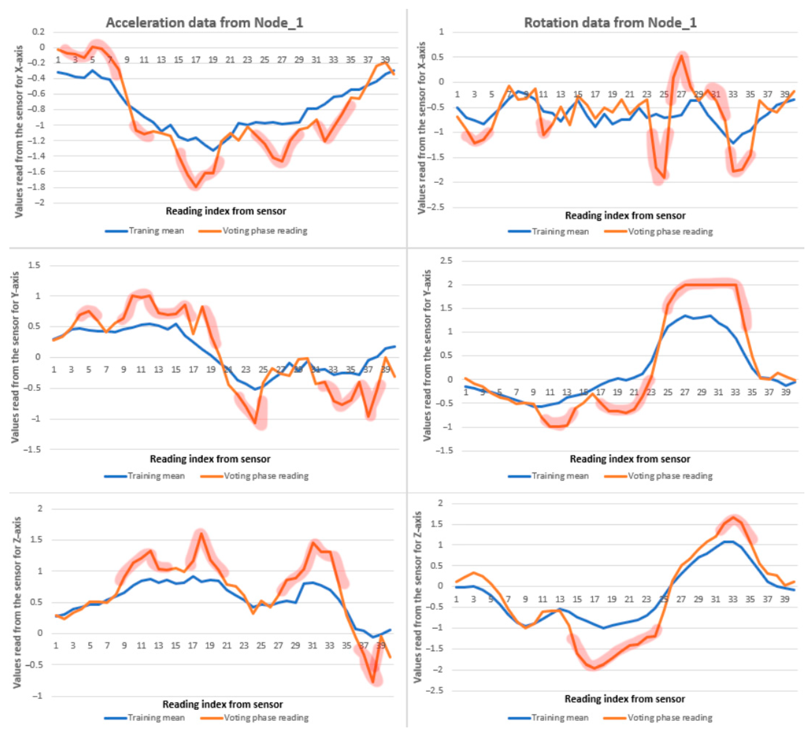
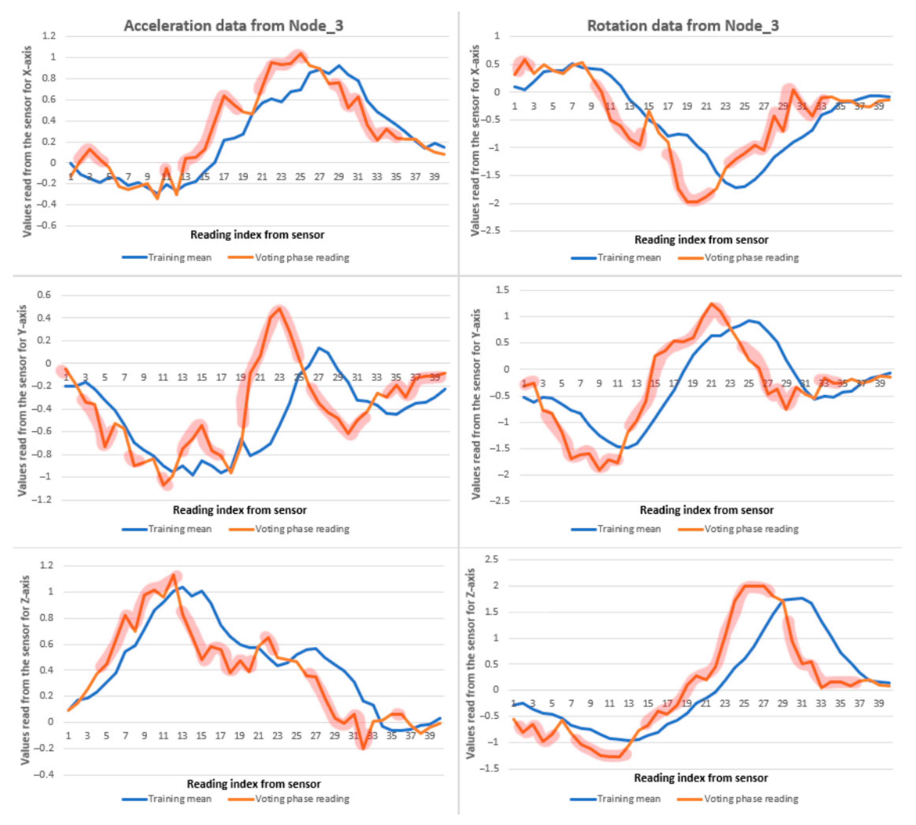
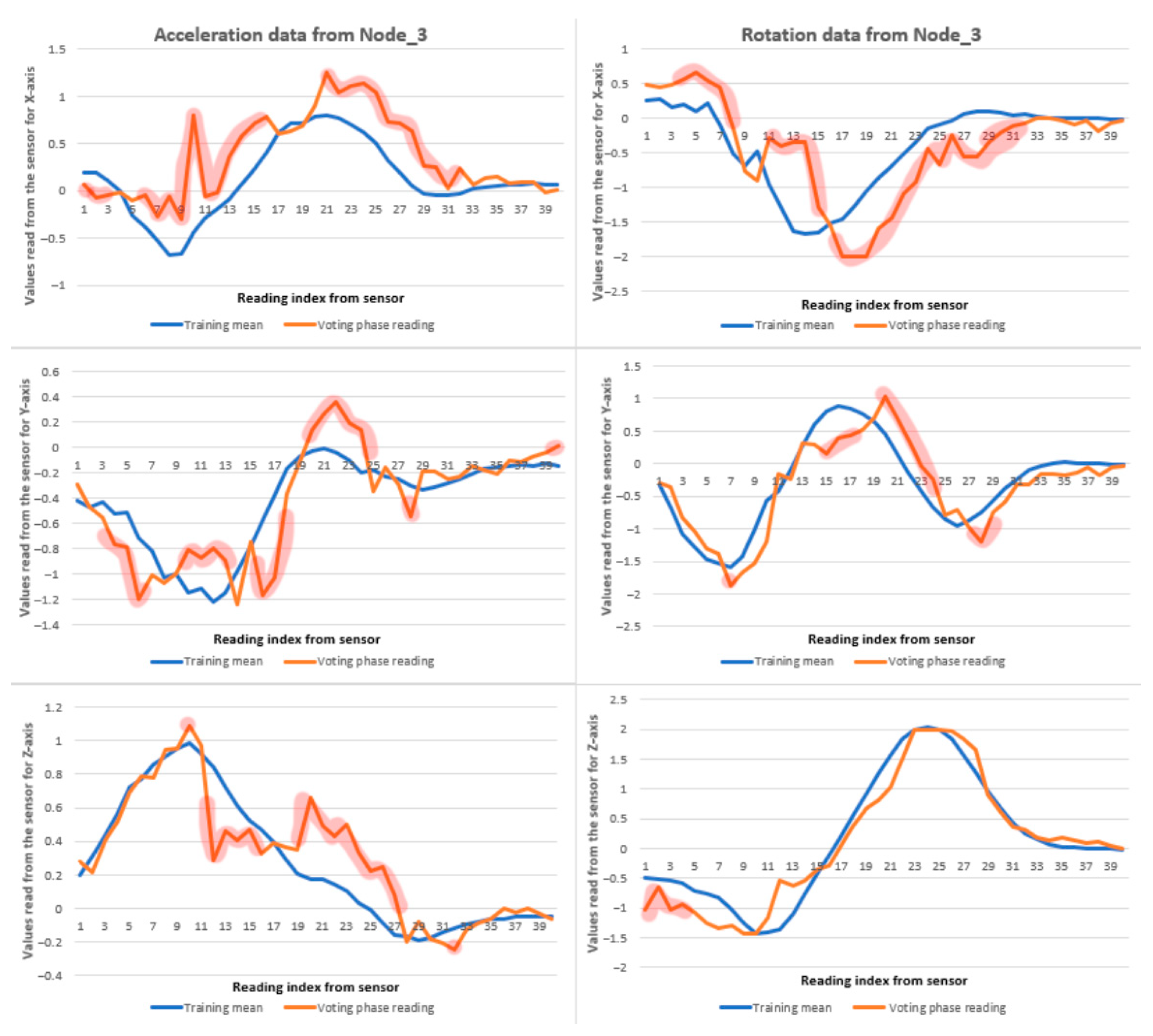
Figure 8,
Figure 9 and
Figure 10 present a series of recorded data samples in water alongside the application of the DTW algorithm and the resulting
similarity percentage computed using the defined formula. The areas highlighted with the read marker indicate deviations in the sensor readings when compared to the mean dataset obtained during the training phase. Although the orange line (representing current readings) does not fully overlap with the blue line (training reference) in several instances, the overall
similarity percentage remains promising. It is evident that, while the trajectories do not perfectly align, the deviation between blue-orange lines exceeds 1 (vertical axis) in only a few isolated cases, suggesting a generally consistent motion pattern.
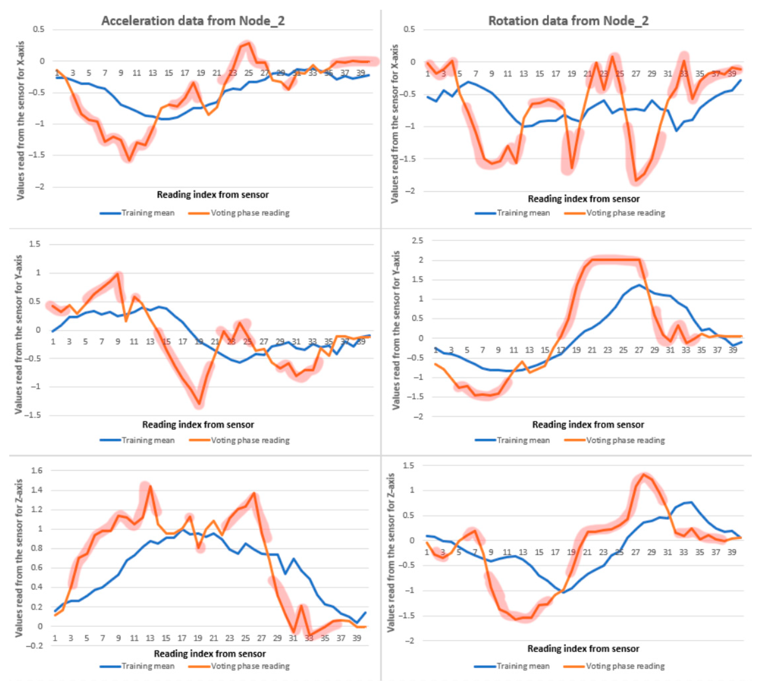
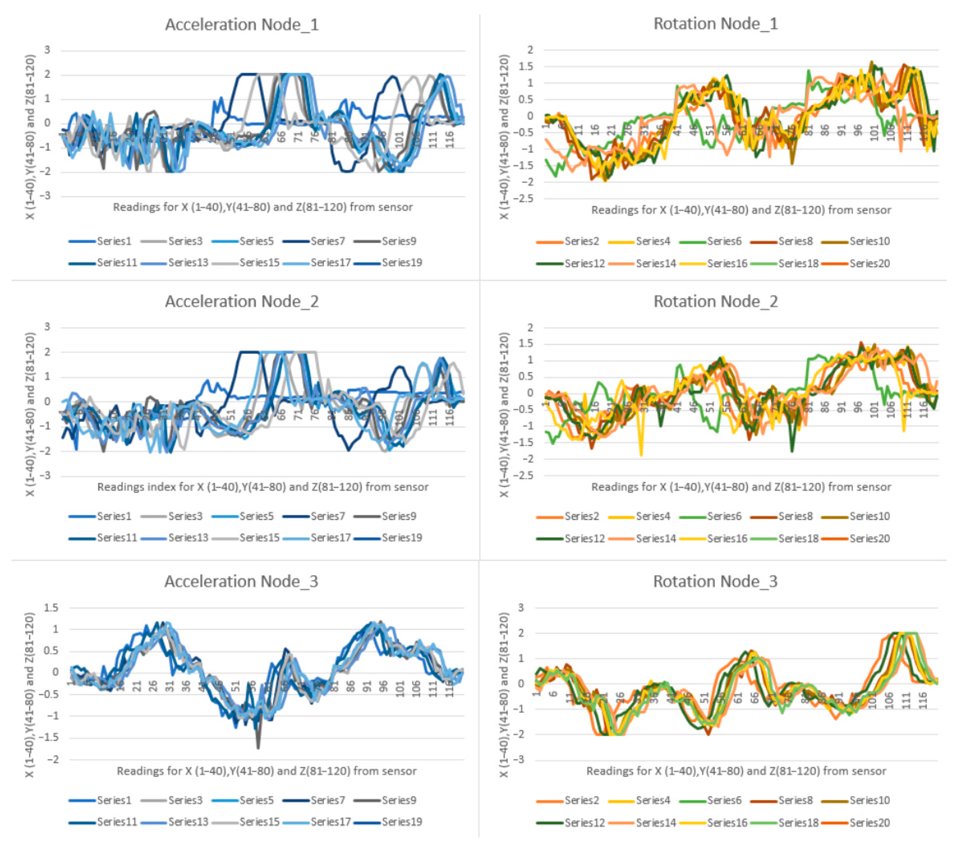
The recorded demonstration of the front crawl swimming stroke corresponds to a single movement of the left arm, from the initial to the final position, as illustrated in
Figure 5. For this test, training was conducted in water, and the corresponding training data is presented in
Figure 11, showing acceleration and gyroscope readings for each sensor node. The graphs display 10 iterations readings of the stroke, where each plotted line represents a full motion cycle. Specifically, the first 40 data points correspond to the
X-axis, points 41 to 80 to the
Y-axis, and points 81 to 120 to the
Z-axis.
An analysis of the training data reveals that for the first two sensor nodes, the recorded values for both acceleration and gyroscope data exhibit inconsistencies across the 10 iterations. In contrast, the data for the third node demonstrates a high degree of consistency, with all iterations following a similar pattern.
This discrepancy is reflected in the results presented in
Figure 8 and
Figure 9, where the similarity outputs for Node_1 and Node_2 are significantly lower, indicating the impact of inconsistent training. Following the training phase, the system computes the mean of the 10 recorded iterations, which serves as the reference pattern during the voting routine. Any deviation from this pattern in subsequent movements leads to reduced similarity scores.
The differences in training quality directly affect the system’s ability to evaluate new movements. For Node_3, where the training data were consistent, the resulting pattern closely matches the new input during the voting routine, leading to a similarity score of 86%. In contrast, Node_1 and Node_2 produced lower similarity scores of 27% and 23%, respectively. Despite the low similarity values, visual inspection of the plotted data indicates that the general shape of the movement was preserved, although with notable deviations from the mean pattern.
These findings emphasize the importance of accurate and consistent training. When the training data are reliable, the system generates a representative pattern that enables effective comparison during real-time evaluation, leading to improved similarity scoring.
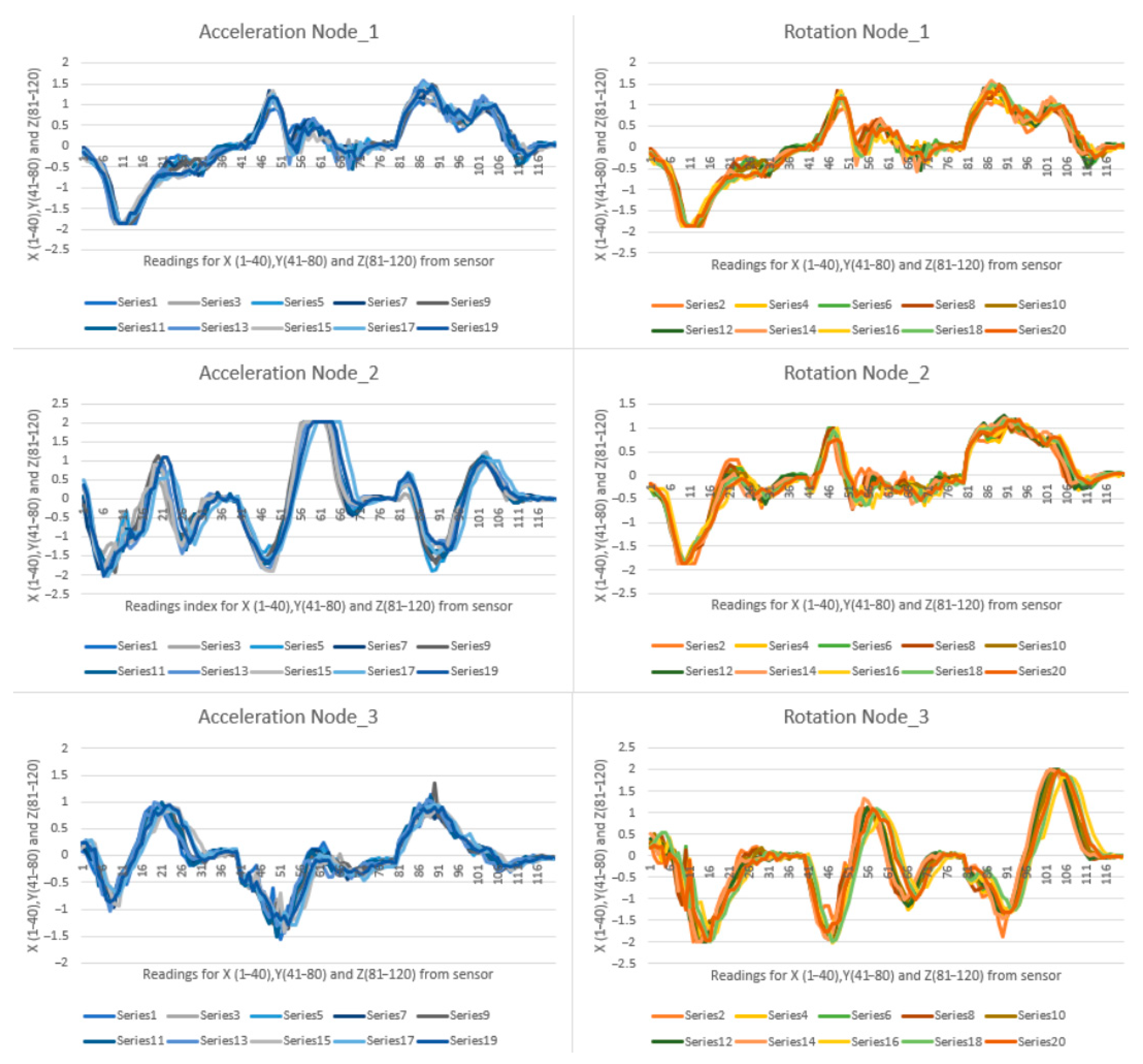
In comparison, if training was performed on dryland and the voting was perfomed also on dryland, the system outputs very good data.
Figure 12 illustrates desirable training performed on dryland.
The voting results obtained during dryland testing, following the described training procedure, fall within the optimal similarity range of 90–100%. These results indicate that a well-established training pattern yields highly accurate motion recognition in controlled, dryland conditions.
Based on these promising outcomes, a new approach was explored: performing the training phase on dryland and subsequently evaluating the voting phase during in-water movement. The following section presents and discusses the results of this cross-environment evaluation.
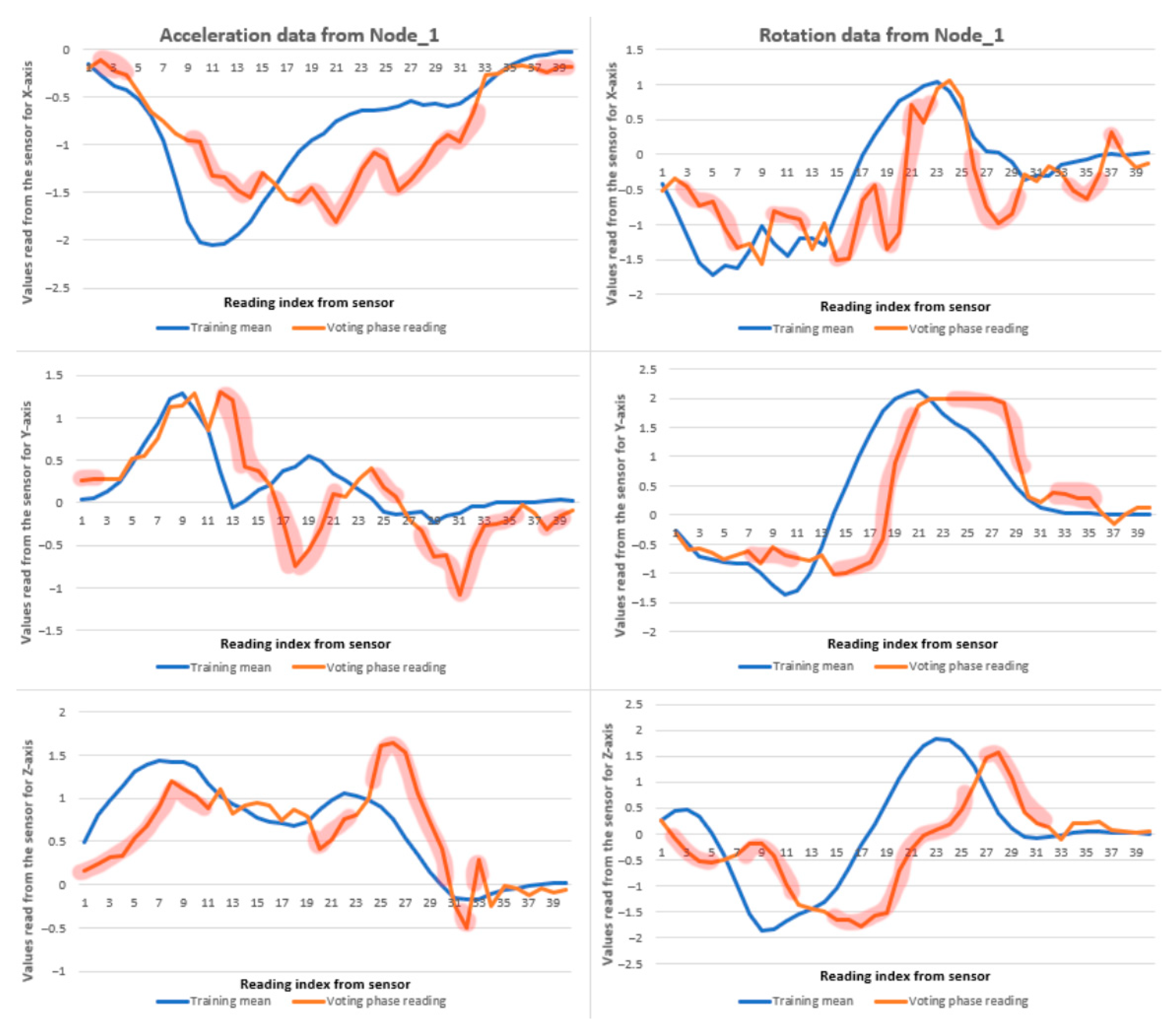
Figure 13,
Figure 14 and
Figure 15 display recorded in-water data samples, accompanied by the application of the DTW algorithm and the corresponding
similarity percentages calculated using the established formula. Red-highlighted areas denote deviations in the sensor readings relative to the mean dataset established during the training phase. While the orange line (current readings) does not fully align with the blue reference line in several segments, the overall similarity score remains high. Notably, deviations exceeding a value of 1 on the vertical axis occur only in a few isolated instances, indicating that the motion pattern is generally consistent despite minor misalignments.
The results obtained when the training phase was conducted on dryland and the voting routine performed in water showed improved performance compared to the scenario in which both training and voting were conducted in water. Specifically, Nodes 1 and 2 exhibited a 30–40% increase in similarity scores for the same stroke type as used in the initial experiment.
To enhance clarity and allow for easier comparison, in
Table 2 outline the key differences between land-based training and in-water training.
Analysis of multiple test iterations, as illustrated in the corresponding figures, reveals that accelerometer data tends to deviate more significantly from the reference pattern during the in-water voting phase. This discrepancy is attributed to the propulsion of the swimmer’s body during the stroke, which introduces additional linear acceleration. In contrast, the gyroscope data remain largely unaffected, as forward movement does not induce significant changes in angular rotation.
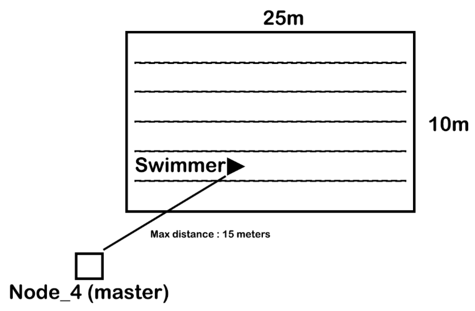
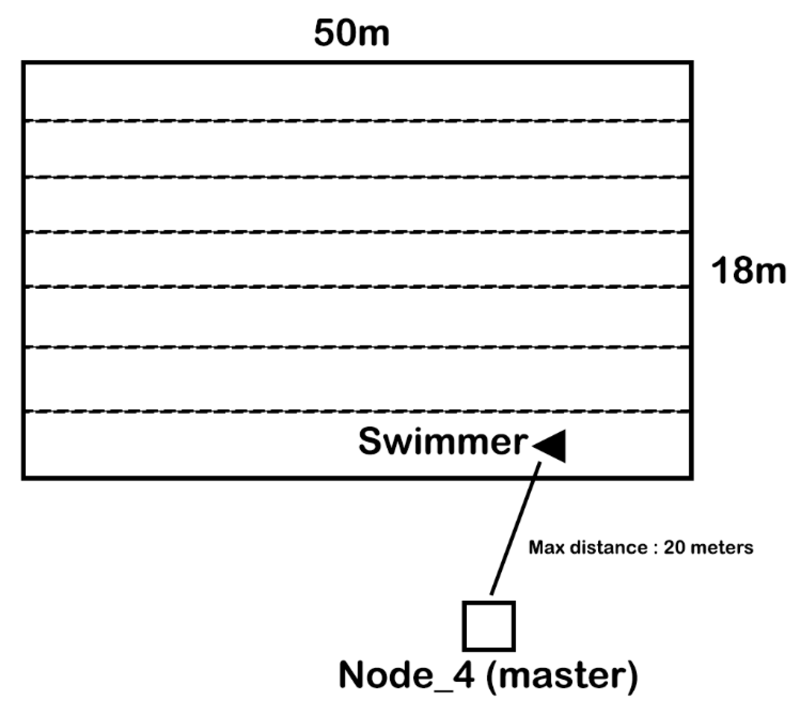
Testing was carried out in two different swimming pool environments:
a smaller pool measuring 25 m in length, 10 m in width, and 1.7 m in depth, as shown in
Figure 16;
a larger pool measuring 50 m in length, 18 m in width, with depths ranging from 2 to 4 m, as shown in
Figure 17.
In the small pool, at least 10 laps of approximately 15 m were performed within range of the master device. In the larger pool, 20 laps covering distances between 15 and 20 m were executed, also within communication range of the master device. In both setups, the master device was connected to a laptop and placed on a chair at the edge of the pool.
Data transmission from the slave nodes to the master device was consistently reliable. No significant data loss was observed during the experiments. Successful data transfer occurred whenever the slave devices were above the water surface. However, transmission attempts made while the devices were submerged were unsuccessful due to the attenuation of Wi-Fi signals in water.
The direct feedback mechanism implemented through the vibration motors on each node functioned reliably; the vibrations were consistently perceptible upon activation and could be clearly associated with deviations from the expected movement pattern at the corresponding sensor location during swimming.
4. Discussion
All testing procedures and results were supervised by a professional swimming coach, who validated both the training movements and the in-water evaluations. The performed strokes adhered to the front crawl technique and were executed in a drill-like manner, rather than as continuous swimming.
The system has proven to be reliable for dryland applications and as noted by the coach, can effectively support technique development through simulated swimming exercises. It is suitable for use across all swimming styles—not only front crawl, as explored in this study, but also breaststroke, backstroke and butterfly. Given its sequential structure and capacity for movement recognition, the system is particularly well-suited as a dryland simulator to assist swimmers in learning and refining specific techniques.
Regarding in-water use, the results are promising. With targeted improvements, the system has the potential to function as an independent swimming assistant, providing real-time feedback via the integrated vibration motors to support stroke correction during training.
In its current state, the system presents several limitations for in-water application:
Inconsistent in-water training: Due to the influence of water movement in the pool, maintaining stable arm positions is difficult. Additionally, the need to stay afloat introduces variability in movement, making it challenging to perform a technically perfect stroke repeatedly for pattern training. These conditions impact the consistency of training data.
Accelerometer sensitivity to full-body movement: As the IMU nodes are attached to the swimmer’s arm, each stroke induces forward propulsion, causing the entire body to accelerate. This effect, combined with the necessary use of leg kicks for buoyancy, introduces additional acceleration values that deviate from the intended motion pattern [
30].
Condensation within waterproof enclosures: The use of sealed plastic bags for waterproofing, combined with the heat generated by the electronic components, leads to condensation inside the enclosure. This occurs due to the temperature difference between the device and the surrounding pool water, potentially impacting long-term reliability and sensor performance [
31,
32,
33].
Lack of continuous monitoring: Currently, the voting routine operates in a start–stop mode. Implementing continuous motion monitoring would allow the swimmer to vary speed or technique more naturally, with the system identifying movement patterns and delivering real-time feedback accordingly.
Despite these challenges, the system demonstrates potential for in-water use, particularly if the similarity scoring formula is adjusted to be less sensitive to minor deviations. Such a modification would make the system more suitable for novice swimmers who are in the early stages of technique development and may benefit from approximate feedback rather than precise professional-grade evaluation, as targeted in this study.
Moreover, the current system reads both accelerometer and gyroscope data from the sensors to compute the similarity output. To enhance the robustness of the voting phase—particularly in aquatic environments where linear acceleration is more susceptible to disturbance—the contribution of accelerometer data could be reduced in favor of a greater emphasis on gyroscope (rotational) data. This adjustment would shift the evaluation from an equal weighting of both parameters to a rotation-dominant approach, potentially improving classification accuracy in the presence of external perturbations.
This paper does not validate the proposed system at a large scale. The primary focus is to evaluate the system’s response, in the described configuration, during the calibration, training, and voting phases performed in a water environment. Additionally, it assesses the Wi-Fi communication between the slave nodes and the master node. The system was tested on a single subject; comprehensive testing involving individuals of varying ages, heights, and swimming skill levels will be addressed in future work. A related study utilizing this device, involving multiple tests and two subjects, is presented in “Learning Swimming Techniques by Means of Real-Time Monitoring with Embedded Devices” paper.
In the presence of differences between movement patterns on land and in water, regarding the training phase, methods to optimize the system for better adaptation to these variations can be explored. This can improve the accuracy and reliability of the application in aquatic environments. The process can be implemented using machine learning algorithms. When employing edge computing, more expensive controllers are required to process results locally based on a stored database and newly acquired movement data. Alternatively, cloud computing can be utilized by sending information from the master node to a cloud-based AI agent during the voting phase. However, this approach may increase response time for the user in water, as latency becomes a significant issue. Verification of training movements from water samples can be performed individually using the Dynamic Time Warping (DTW) algorithm, rather than averaging all ten data series from the training phase. This approach enables evaluation of a movement during the voting phase against a comprehensive database of movements, although it will increase computation time. Future studies could explore this logical implementation and its impact on system performance.
DTW was used primarily as a baseline approach for evaluating movement similarity. Further optimization may be achieved through parameter tuning, such as applying time constraints or adjusting pattern characteristics (based on different swimming strokes). Additionally, incorporating preliminary verification of the incoming data to decide whether a movement requires full DTW analysis could reduce CPU load on the controller. Integrating machine learning architectures has the potential to further enhance the accuracy of swimming movement recognition. Decision Trees or k-Nearest Neighbors classifiers can be employed for preliminary verification to efficiently determine whether full DTW analysis is necessary [
34,
35,
36].
While it is not mandatory to record 10 iterations during training, since a single perfect repetition by the user can serve as the movement pattern, collecting multiple movements and computing their mean enhances the reliability and robustness of the movement template. This can be configured into an interface used with the master node in the future.
Effective classification of swimming movements relies on accurately distinguishing genuine arm stroke deviations from confounding motion artifacts such as gyroscope drift and body-induced rotations (e.g., body roll and forward motion). These artifacts can obscure stroke-specific features essential for Dynamic Time Warping (DTW) analysis, reducing its robustness. To address this, a comprehensive signal preprocessing pipeline is employed, including drift correction via sensor fusion, reference frame alignment, high-pass filtering to suppress low-frequency and translational noise, segmentation based on motion events, movement onset detection, and feature normalization. These preprocessing steps—particularly sensor fusion, orientation compensation, and filtering—significantly improve data quality by minimizing external motion disturbances. Furthermore, this approach enhances the system’s generalizability and lays the groundwork for handling previously untested edge cases, ultimately increasing the reliability and adaptability of stroke error identification in diverse real-world conditions.


