Article

A Measurement-Driven Method for the Simultaneous Solution of AX = YB in the Implementation of Simulated Robotic Production Systems

by
Wojciech Andrzej Szulc
1,* and
Piotr Czop
2
1
Faculty of Mechanical Engineering and Robotics, Department of Robotics and Mechatronics, AGH University of Science and Technology, 30-059 Kraków, Poland
2
Department of Transport and Computer Science, WSB University, 41-300 Dąbrowa Górnicza, Poland
*
Author to whom correspondence should be addressed.
Appl. Sci. 2025, 15(12), 6706; https://doi.org/10.3390/app15126706
Submission received: 19 May 2025 / Revised: 9 June 2025 / Accepted: 11 June 2025 / Published: 15 June 2025

Abstract

This paper presents a novel, measurement-driven method for the simultaneous estimation of the User Coordinate System (UCS) and Tool Center Point (TCP) in industrial robot systems, formulated as a solution to the AX = YB calibration problem. The proposed algorithm minimizes the discrepancy between simulated and real-world robot poses by iteratively refining both coordinate transformations using external laser tracker measurements. A comparative evaluation was conducted using two ABB IRB-6640 robots and four calibration strategies, including internal three-point measurement, absolute orientation, geometrical referencing, and the proposed method. Experimental results show that the proposed approach outperforms standard industrial techniques, achieving an average translational error below 0.4 mm, compared to over 2 mm for conventional methods. The geometric method, while widely used for its simplicity, demonstrated the highest error and instability due to poor rotational alignment. The findings validate the proposed solution as an accurate, non-invasive alternative for implementing simulated programs in real production environments, particularly where direct access to robot controllers is limited.

1. Introduction

Under modern production conditions, industrial robotic lines rely on automated robotic solutions, where rapid commissioning is a critical requirement. This demand has driven the development of methods aimed at improving deployment efficiency and system flexibility. Various strategies have been explored, including automated commissioning of offline-generated programs [1], true effectiveness in single-pass commissioning [2], low-code programming platforms [3], and rapid configuration techniques for robotic cells [4]. Lastly, Janssen, Falk, and Schmitt [5] examined efficient commissioning methods tailored for final automotive assembly lines, emphasizing time and cost savings during setup.
The measurement process in implementing offline simulated programs is a crucial step in matching simulation of a production line with the real environment, the so-called base frame calibration. Base frame calibration refers to the process of determining the relative translation and rotation between the robot’s WORLD frame and local coordinate system. It is essential for enabling accurate position and orientation transformations required for coordinated control of robot end-effectors [6]. The importance of accurate base frame calibration has grown alongside the widespread adoption of offline programming (OLP) and virtual commissioning (VC) practices in the automotive industry. Processes such as spot welding, arc welding, gluing, and riveting rely heavily on simulated robot programs prepared using both proprietary and independent simulation software [7]. OLP and VC are closely linked to the digital twin (DT) concept, which plays a critical role in the Industry 4.0 revolution, facilitating the management, optimization, and commissioning of industrial robots [8]. There are three typical measurement methods for determining the reference position and orientation of the User Coordinate System (UCS) of tooling stations and other equipment of robotized cells:
(a)
The robot’s internal direct three-point measurement method—frequently inaccessible due to reference positions being out of reach.
(b)
The indirect measurement method using one of the AX = BY solutions.
(c)
Geometrical estimation of the robot world coordinate frame with aligned UCS in the measurement system.
An equally critical measurement step for accurately transferring executable path programs from a simulated environment to a real-world system is the determination of the Tool Center Point (TCP), which defines the origin of the coordinate system of the tool mounted on the robot’s flange. This can be accomplished using one of the following methods:
(a)
Utilizing the robot’s internal TCP measurement function;
(b)
Direct numerical import of CAD data from modeling software;
(c)
Tool measurement performed at the manufacturer’s site prior to mounting on the flange.
In this manner, successful implementation of offline-simulated path programs in real manufacturing environments requires two critical measurement processes: the accurate determination of the Tool Center Point (TCP), and the calibration of the robot’s base frame, commonly referred to as base frame calibration. These two measurements are inherently interdependent, as both are necessary for aligning the simulated kinematics with the physical robot setup.
This dual-calibration challenge is often mathematically formulated using the calibration equation AX = YB, where
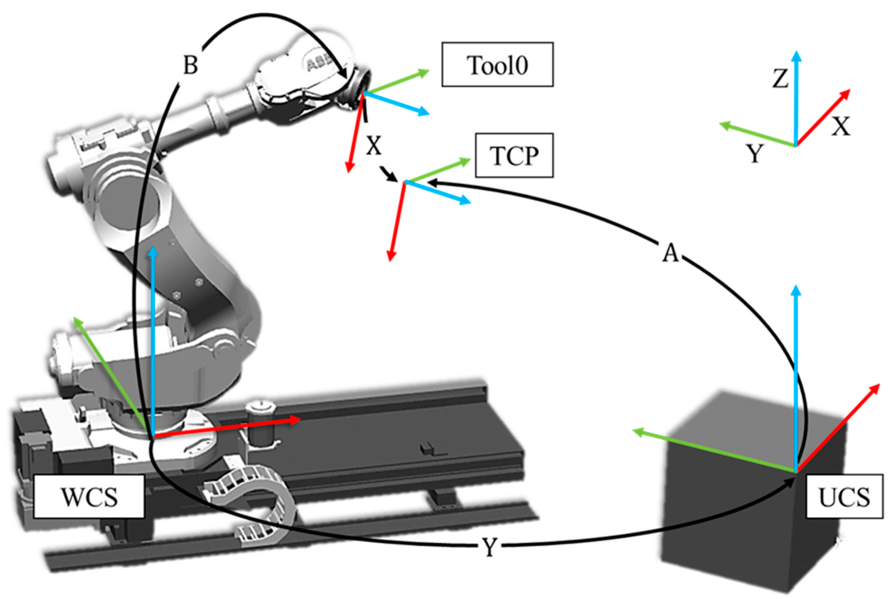
  • X represents the unknown transformation from the robot’s flange to the TCP (TCP translation);
  • B is the known robot joint transformation computed from Denavit–Hartenberg (D-H) parameters [9];
  • Y is the transformation from the WORLD coordinate system to the BASE (or UCS);
  • A is the measured TCP position in the local UCS, often obtained from an external measurement system.
Solving this equation ensures that the tool position and orientation in simulation can be accurately reproduced by the physical robot. Since both the UCS and TCP are typically unknown in real-world applications, simultaneous estimation of both variables has been proposed and addressed in several studies [10,11,12]. Figure 1 illustrates the relationships among the relevant coordinate systems and their transformations.
This work introduces a novel, measurement-driven calibration method that simultaneously estimates the UCS and TCP without requiring access to internal robot controllers. By leveraging high-precision external measurements, the proposed approach achieves sub-millimeter accuracy and demonstrates robust performance across varying configurations, making it especially well-suited for industrial applications involving digital twins and offline programming. The increasing reliance on offline programming (OLP) and digital twin technologies in modern robotic production lines has made accurate alignment between simulated and physical environments a critical requirement. The motivation for addressing this research includes the following:
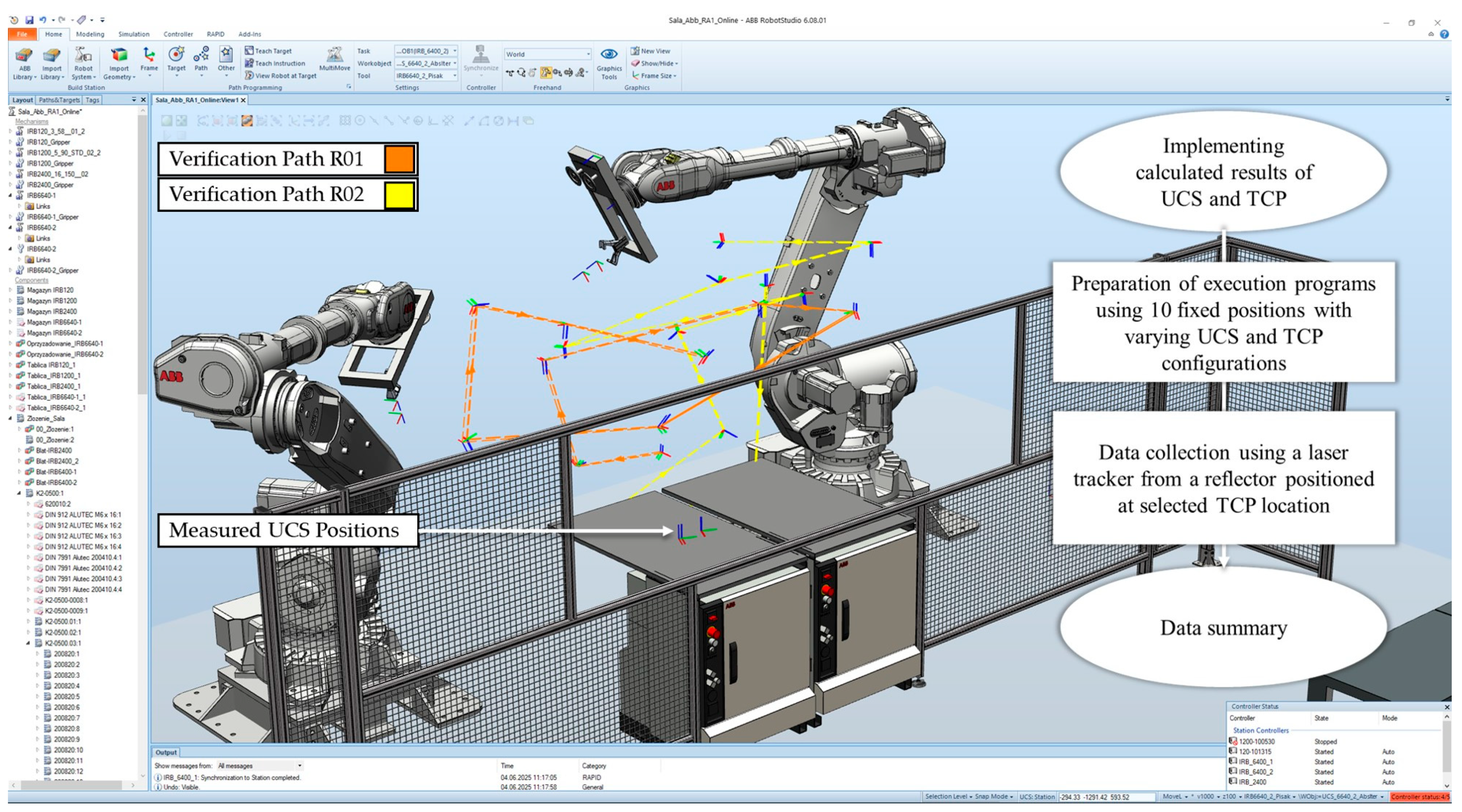
  • Reduction of implementation steps—simplifying the deployment of simulation-based robot programs by minimizing the number of required measurement procedures.
  • Shortened commissioning time—enabling more efficient integration of executable programs onto real robotic systems.
  • Robot-specific accuracy—allowing for the best-fitting calibration solution to be directly tailored to each individually measured robot, improving positional precision.
  • Scalability in multi-robot setups—increasing the efficiency of calibration processes in production cells involving multiple robots operating on a shared tooling station.
This article is organized as follows: Section 2 presents a comparative evaluation of four methods for estimating the User Coordinate System (UCS) and Tool Center Point (TCP), including a newly proposed algorithm. Section 2.1 outlines each method, while Section 2.2 describes the experimental setup using two ABB IRB-6640 robots and a Leica laser tracker. Section 2.3 details the data recording process combining internal robot calibration and external coordinate alignment. Section 3 introduces the iterative estimation algorithm based on an AX = YB formulation, and Section 4 presents the comparative validation results. The paper concludes with a summary of the findings and the demonstrated advantages of the proposed approach in bridging simulation and real-world robotic applications.

2. Comparative Evaluation of UCS and TCP Estimation Methods

To evaluate the performance and robustness of the algorithm proposed in Section 3 for joint estimation of the User Coordinate System (UCS) and Tool Center Point (TCP), a comparative verification study was conducted. This study involved four distinct methods commonly used in industrial and academic practice for UCS and/or TCP determination. The objective was to assess the accuracy, consistency, and reliability of each method under equivalent measurement conditions.

2.1. Overview of the Compared Methods

The following methods were included in the comparative evaluation:
Method A—robot’s internal three-point UCS and internal TCP measurements. This baseline method utilizes the robot controller’s native functionality for UCS definition via the so-called three-point method, in which the user manually defines the UCS using three spatially distinct points on a calibration fixture. The robot’s internal TCP measurement routine is used to localize the tool frame. This method reflects standard industrial practice and serves as a reference for real-world usage accuracy [13].
Method B—absolute orientation via B. K. P. Horn’s closed-form solution. In this approach, the UCS is estimated using B. K. P. Horn’s absolute orientation algorithm, which provides a closed-form least-squares solution for rigid transformation between two sets of corresponding 3D points. In this method, a set of measured points in the robot’s base coordinate system is matched to the same points represented in the UCS. The robot’s internal TCP measurement is used directly without modification. This provides a mathematically optimal UCS transformation under the assumption of noise-free point correspondences [14].
Method C—UCS Estimation via geometrical measurement of the robot’s world frame. This method involves manually measuring the geometric location and orientation of the robot’s World Coordinate System (WCS) using physical reference of the robot’s construction. The orientation and position of the WCS are then used to construct the UCS using a transformation matrix. The TCP remains as defined by the robot’s internal measurement. This method is representative of a hybrid manual–geometric approach often used in industrial calibration scenarios. Geometrical estimation methods are also under constant development with multisensory studies [15] and terrestrial scanner systems [16].
Method D—joint UCS and TCP estimation via the proposed algorithm. The novel method under evaluation estimates both the UCS and TCP parameters simultaneously. The method minimizes residual errors between observed robot poses and reconstructed transformations using an iterative estimation approach, inspired by the absolute orientation problem; however, it is extended to include both TCP offset and UCS transformation. This method is particularly advantageous in scenarios where neither the TCP nor the UCS is known a priori.

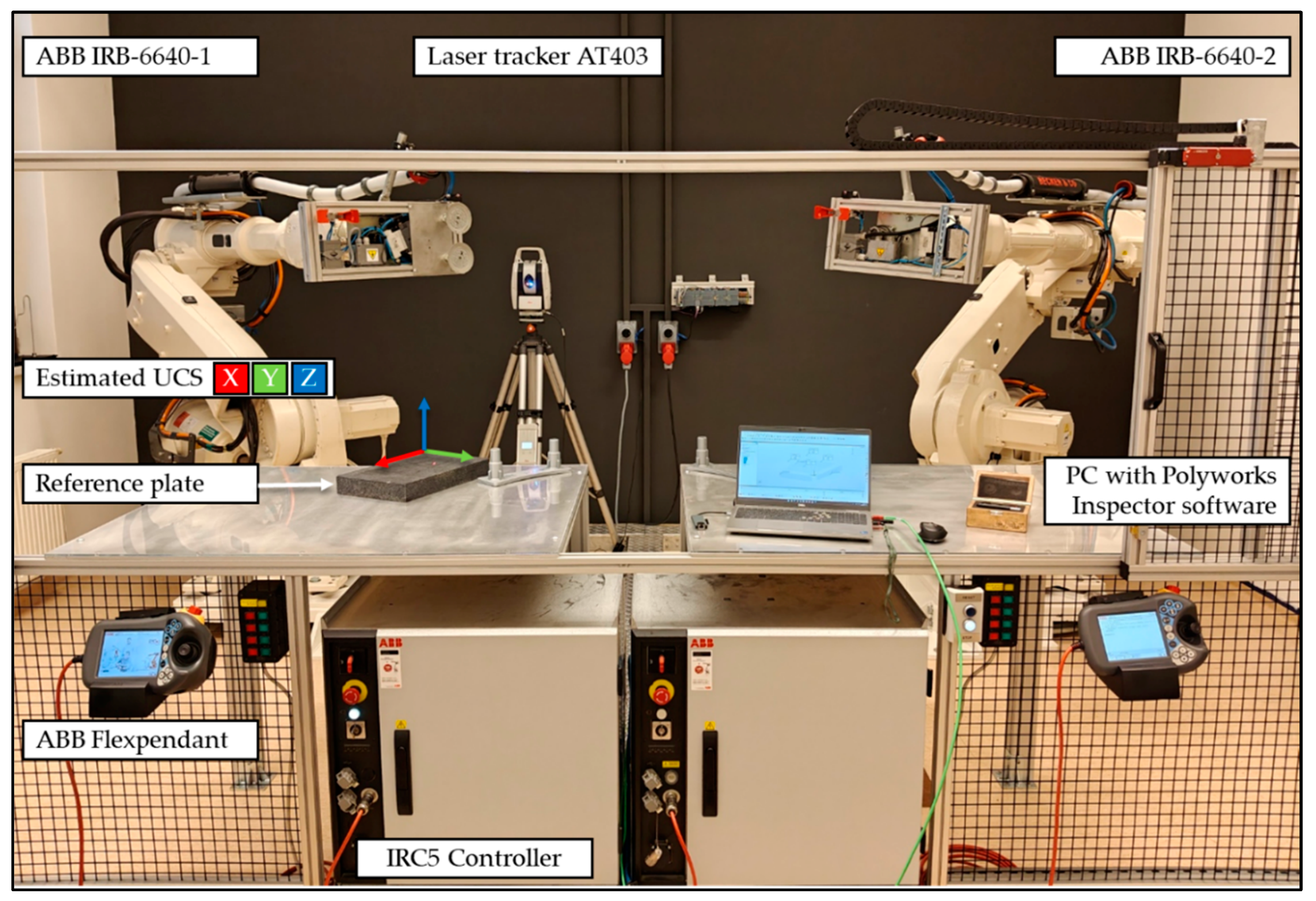
2.2. Experimental Setup for UCS and TCP Estimation Evaluation

The four selected methods were tested using a Leica laser tracker AT 403 measuring system, which is a class of position reading several times higher in relation to industrial robots. The laboratory robotic cell consisted of two ABB IRB6640 robots with a 130 kg payload, 3.2 m workspace radius, and IRC5 robot controllers. Although ABB robots represent orientation using quaternions, all calculations in this study were performed using their equivalent 3 × 3 rotation matrix representations to ensure compatibility with the applied transformation and estimation algorithms [17]. The collected data have been aligned with a fixed granite reference plate and gathered via Polyworks Inspector® 2023 probing software and a Tooling Ball Reflector 0.5” (TBR). Each robot system has been examined separately in each performed measurement. The laboratory stand is presented in Figure 2. Robot TCP position transformations were read on the controller side together with the laser position reading. Ten positions were randomly chosen within the assumed robot workfield, varying both the tool’s orientation and position. Depending on the selected method, robot readings were recorded either with or without TCP translation, without causing any actual change in the robot’s physical position. Each method was applied to estimate the UCS (and TCP where applicable), and the results were compared using the positional error of estimated points in the UCS compared to ground-truth coordinates and residual transformation error—the difference between expected and reconstructed robot poses. Calculations have been performed in Mathworks MATLAB® software, version R2020a, using selected algorithms.

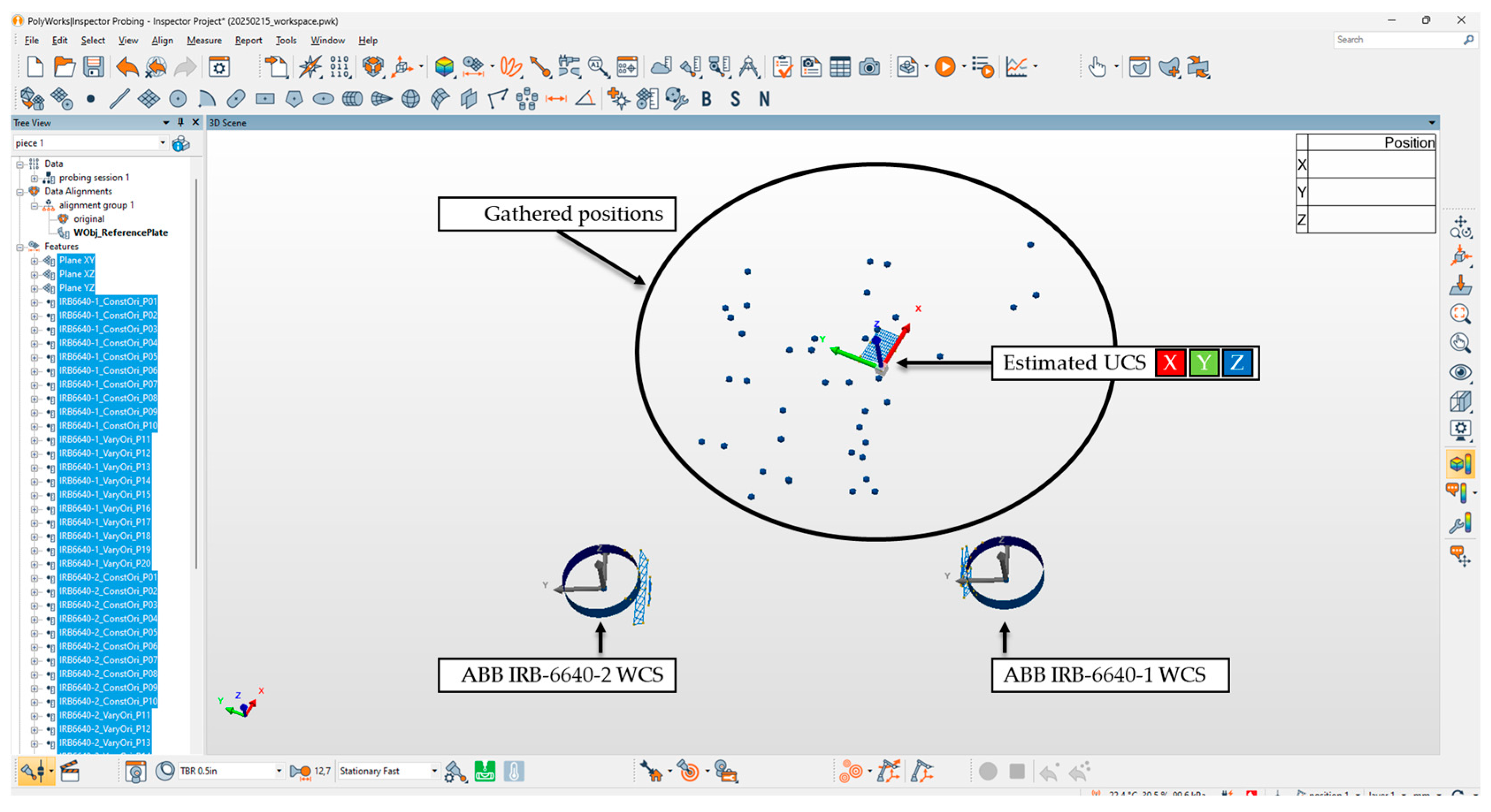
2.3. Data Recording Process

To ensure accurate and repeatable measurements, a structured multi-step procedure was followed for data acquisition and alignment. Each step was designed to progressively refine the robot and measurement system configuration to enable reliable coordinate system estimation. The data recording process consisted of steps performed internally in the robot system (0–2) and using external Polyworks Inspector® 2023 probing software for coordinate system alignment and data sampling. Figure 3 presents a graphical representation of the gathered data and geometrically estimated (Method C) position of the World Coordinate System (WCS) of each robot. The steps of the procedure are outlined below:
Step 0: Payload Configuration
The robot’s payload mass and center of gravity were measured and entered into the controller.
Step 1: TCP Measurement
The Tool Center Point (TCP) was measured using dedicated conical fixtures and probing routines.
Step 2: Robot Program Preparation
Robot programs were created to reach multiple angular poses distributed across the robot’s workspace.
Step 3: UCS Alignment in PolyWorks Inspector®
The User Coordinate System (UCS) was aligned in the PolyWorks Inspector using laser scan data from three orthogonal planes on a reference calibration plate.
Step 4: WCS Alignment in PolyWorks Inspector®
The World Coordinate System (WCS) was aligned based on the cylindrical geometry of the robot’s base pedestal and the flat surface of the fixture plate.
Step 5: Data Sampling
Data samples were recorded using a shared robot program. A temporary TCP was defined using a dedicated hole feature that held a reflector for repeatable positioning.

3. Iterative Estimation of Coordinate Transformation and TCP Translation

The transition from simulation to real-world execution is hindered by the discrepancy between a robot’s high repeatability and its significantly lower accuracy, which is affected by multiple error sources, such as joint offsets, geometric imperfections, and environmental factors. Accurate simulation implementation requires extensive calibration, external measurement systems, and error compensation methods, which are often costly and impractical for every production scenario. Several studies have addressed the simultaneous solution of the AX = YB calibration problem [11,18,19,20], providing a basis for future comparative analysis with the method proposed in this work. In this study, a methodology for robotic station measurement, including mass identification, was implemented based on the methodology and block diagram representation outlined in [2]. As a starting point, the AX = YB equation can be reformulated as follows:
C i T Z 1 = R A i + T , f o r i = 1 , , N
where
C i —the 4 × 4 transformation matrix from the robot’s internal positioning system (pose of the robot’s flange).
A i —the measured 3 × 1 position of the tool from an external tracking system (e.g., a laser tracker).
T Z —the 3 × 1 translation vector representing the translation of the TCP in the tool coordinate frame.
R —3 × 3 rotation matrix representing orientation between the World Coordinate System (WCS) and the User Coordinate System (UCS).
T —3 × 1 translation vector from WCS to UCS.
The TCP translation is initialized and estimated by averaging estimated translations from all N measurements:
T z = 1 N i = 1 N T i
Each point B i in the robot’s base frame is calculated using the estimated TCP:
B i = R i T z + T i
Centroids of both measurement sets are calculated to enable zero-mean alignment:
A ¯ = 1 N i = 1 N T A i , B ¯ = 1 N i = 1 N T B i  
A ~ i = A i A ¯ , B ~ i = B i B ¯
The cross-covariance (correlation) matrix is computed, followed by Singular Value Decomposition (SVD) and calculation of the rotation matrix R . To ensure proper rotation, the determinant is checked:
H = i = 1 N A ~ i B ~ i T = A ~ · B ~ T  
H = U Σ V T
R = V U T ,   i f   d e t ( R   ) < 0 : V : , 3 = V : , 3 , R = V U T  
The translation T from WCS to UCS is calculated by aligning centroids:
T = B ¯ R · A ¯
A refined TCP estimate is computed for each sample and averaged for the new estimation:
T z , i = R i T R A i + T T i  
T z = 1 N i = 1 N T z , i  
The process iterates until the change in TCP estimation between iterations is smaller than a defined threshold:
T z k T z k 1 < ε  
where
k—iteration index.
ε—convergence threshold.
To evaluate fit accuracy, the residual error for each measurement is computed, finding the scalar error.
R e s i = C i 1 : 3 , : · T Z 1 R A i + T  
e r r i = R e s i e r r V e c = e r r 1 e r r N  

4. Comparative Validation Based on Measurement Data

A verification process has been conducted with all possible combinations of TCP and UCS, giving 80 measurement pairs with fixed coordinates in batches of 10 points. A representation of this process is presented in Figure 4 together with a block diagram. The visible difference in measured UCS highlights the discrepancy between simulation assumptions and the actual mounting positions of these two robots, reflecting deviations from real-world conditions. Measurements were collected, analyzed, and organized into four main series of 20 samples each. Each series corresponds to a specific UCS estimation method, and within each series, two subsets of 10 samples were recorded using the TCP from internal measurements and from the algorithm-estimated solution.
Using the robot’s internal TCP measurement method is inherently dependent on manual input, reference point positioning within the workspace, and operator skill. In this study, the accuracy of the internal TCP procedure was validated by ensuring the mean measurement error did not exceed 0.5 mm—an accuracy level typically sufficient for most industrial applications. This internal method is a commonly used procedure for calibrating the Tool Center Point (TCP) of an industrial robot. It involves reaching a fixed reference point with the tool from at least four different orientations, allowing the robot to calculate the exact position of the TCP relative to the robot flange. A threshold of 0.5 mm for the allowable average measurement error using the internal method is sufficient, as such limits are typically defined by individual facilities during manual measurements with the robot. When working with high-volume tooling, even achieving this level of accuracy can be challenging in manual processes. Moreover, the issue of absolute accuracy in industrial robots can further worsen the measurement reliability depending on the location within the robot workspace [2,21]. In the first subset, the TCP was introduced using the robot’s internal measurement procedure. In the second subset, the introduced TCP was a result of the proposed algorithm in this paper. The four UCS estimation approaches evaluated in this study were as follows:
  • Robot internal method (3Point)—Method A: UCS defined using the robot’s internal three-point procedure.
  • Absolute orientation solution (Absor)—Method B: UCS estimated using the absolute-orientation-based algorithm, with a predefined TCP.
  • Geometrical estimation—Method C: UCS defined from geometrical referencing of the robot base and surrounding fixture.
  • Proposed algorithm (AbsIter)—Novel Method D: UCS and TCP jointly estimated using the proposed method with additional robot orientations.
For each sample, the tool position was measured and compared to the reference position computed from the robot’s transformation data. Absolute translational differences along the X, Y, and Z axes were calculated, and both per-axis and overall positional errors were evaluated. Each selected result has been gathered in Table 1.
The results are presented in Plots 1–4, showing the absolute average translational difference in all three directions for each individual measurement point. The error is calculated using Formula (15), which compares the position measured by the external system with the corresponding robot read values. For each robot, two diagrams are provided: one using the TCP obtained from the internal robot measurement routine and the other using the TCP estimated with the proposed method.
Δ T ¯ = X M X R + Y M Y R + Z M Z R 3  
The outcome from the geometrical estimation method differs significantly from the other results due to high translational errors, with deviations ΔT reaching over 5 mm, as shown in Table 2 and Table 3. The error in the geometric method indicates a very poor fit of the WCS, which cannot be detected during the measurement stage itself but only becomes evident after performing the calculations, ultimately making this method unsuitable for effective deployment of simulations into real-world environments. However, it is worth noting that geometric estimation methods are still widely used in industrial settings due to their non-invasive nature and independence from robot controller access, similar to the motivations discussed in [22,23], where external measurements were leveraged to reduce reliance on internal robot interfaces.
Compared to the method proposed in this paper, the geometric approach lacks robustness, especially under varying orientations. In contrast, the new iterative method resembles techniques such as those in Tabb et al. [18] and Shah [12], which also tackled the AX = YB formulation through iterative or separable solutions, but without integrating measurement-driven feedback for simultaneous estimation. The measurement-based refinement strategy adopted here is akin to that in Ali et al. [24], where pose and reprojection errors were minimized iteratively, but differs by grounding the calibration in physically measured transformations rather than simulation-generated or vision-based estimates.
Furthermore, while Strobl and Hirzinger [12] introduced a metric on SE(3) to optimize the AX = ZB solution based on system stochasticity, and Pan et al. [23] applied convex optimization through LMI-SDP for robustness, these methods primarily focused on mathematical optimality under noise rather than the specific industrial deployment scenario addressed here. The proposed method uniquely aligns with real-world deployment constraints by combining accurate, external laser measurements with iterative optimization of both the TCP and UCS, demonstrating an average translational error below 0.4 mm—surpassing the performance of most state-of-the-art techniques.
Figure 5 presents a comparison of translational errors (ΔT) obtained through different calibration methods used to define local coordinate systems (UCS) for an industrial robot. A noticeable fluctuation in error values, particularly in the geometrical method, highlights the inherent instability in estimating rotational components of the coordinate system, which directly affects translational consistency. This apparent instability stems from the fact that during the reference-point-based calibration process, the tool approaches the target from various angles. As the orientation of the tool (i.e., angle of incidence) changes, small angular misalignments in the UCS lead to amplified deviations in the calculated TCP position, especially when the tool is long or offset from the flange. These changes introduce variations in the resulting translational components, as clearly visualized in the plotted curves.
If one were to measure rotational discrepancies directly between UCS pairs, it would require collecting laser-based 3D coordinates of three non-collinear points at each robot pose to accurately compute the orientation of the local frame. While this approach was not applied here, similar angular effects can already be indirectly inferred from the graph: by examining the number and magnitude of outlier points (peaks or drops) deviating from the general trend line. These spikes suggest momentary inconsistencies in orientation estimation that manifest as fluctuating translational error.

5. Summary and Conclusions

This study presented a novel iterative algorithm for simultaneous estimation of the User Coordinate System (UCS) and Tool Center Point (TCP) and benchmarked its performance against three industrially recognized methods: internal three-point calibration (Method A), absolute orientation with predefined TCP (Method B), and geometrical estimation of the robot’s world frame (Method C). In contrast to mathematical optimization-focused techniques such as SE(3)-based minimization [12] or LMI-SDP formulations [23], the presented method is measurement-driven and specifically suited for industrial deployment scenarios. It addresses practical limitations highlighted in prior studies, such as rotational instability in geometric methods [24]. By combining the strengths of data fidelity with iterative stability, the method positions itself as a robust, flexible, and implementation-ready alternative for digital twin alignment and offline program commissioning in Industry 4.0 applications.
The experimental validation was conducted using two ABB IRB-6640 industrial robots and a high-precision laser tracker, yielding the following key findings:
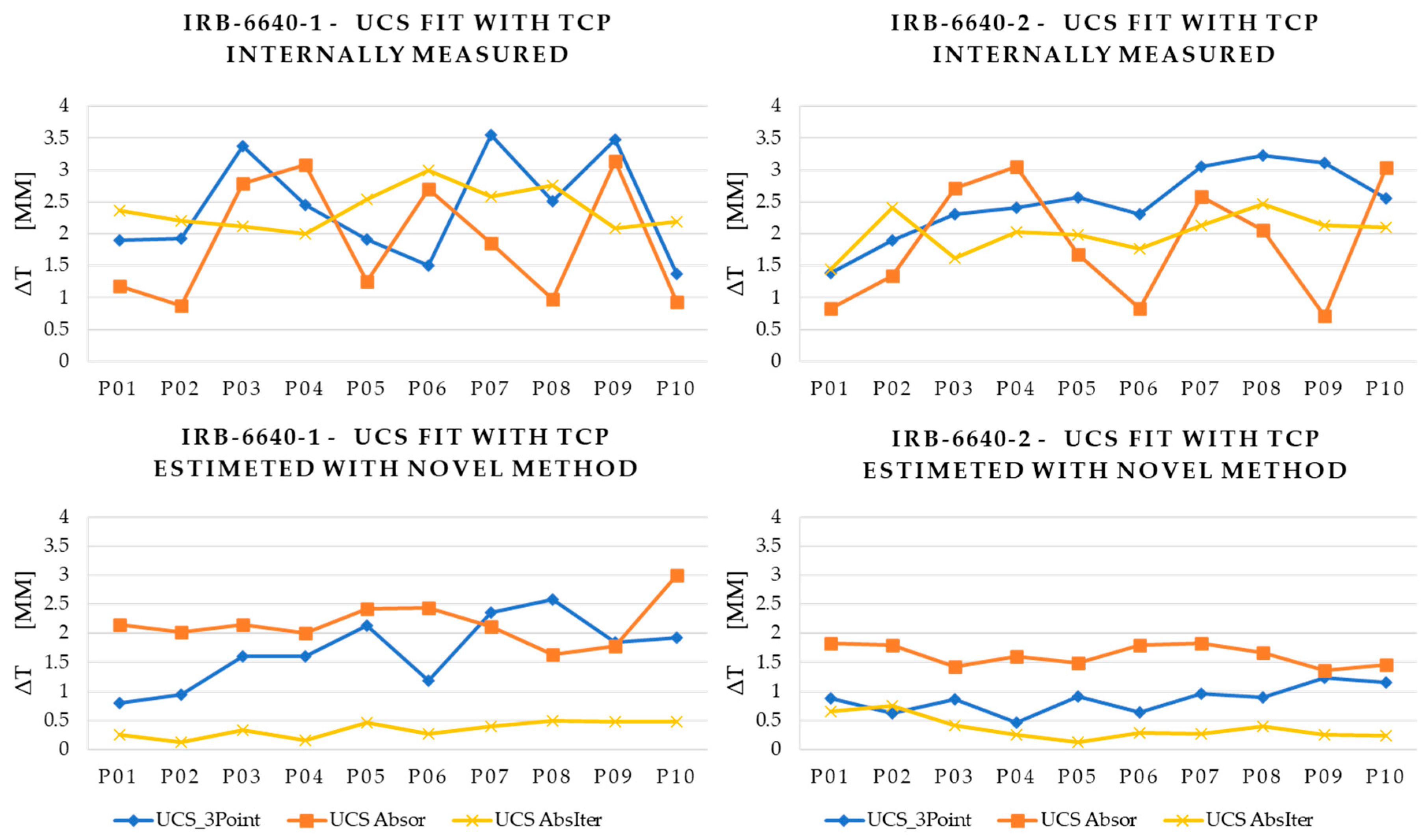
  • Accuracy improvement: The proposed method (M4) consistently achieved the lowest average translational errors, with mean ΔT values of 0.345 mm (R01) and 0.364 mm (R02) when paired with its own TCP estimation. In comparison, the commonly used internal three-point method (M1) resulted in average errors of 2.399 mm (R01) and 2.483 mm (R02), while the absolute orientation method (M2) showed errors of 1.878 mm (R01) and 1.886 mm (R02). Even when those methods were enhanced with the proposed TCP, their errors remained significantly higher than those achieved by the full M4 approach. This represents an accuracy improvement of over 80% in translational error reduction relative to standard industrial techniques, confirming that joint optimization of UCS and TCP yields superior positional precision.
  • Stability across configurations: The proposed algorithm maintained robust performance across varying robot poses and tool orientations, showing low variance in ΔT across all ten test points. It outperformed or matched the absolute orientation method (M2), which showed average ΔT values of 1.88 mm (R01) and 1.89 mm (R02).
  • Limitations of geometric estimation: The geometric estimation approach (M3) demonstrated the poorest results, with translational errors as high as 18.05 mm in some positions and significant instability across measurement series. These errors stem from misalignment in WCS estimation, particularly in rotation, which is not detectable during measurement but emerges only after offline computation. This approach is not recommended as it depends directly on the quality of the robot’s structural elements, which may be inconsistent.
  • Impact of TCP estimation: In all evaluated methods, replacing the robot’s internally defined TCP with the one estimated by the proposed algorithm led to substantial improvements. For example, using internal TCP with the three-point method yielded a mean ΔT of 2.40 mm (R01) and 2.48 mm (R02), while integrating the proposed TCP reduced errors to 1.70 mm and below.
  • Industrial applicability: The novel method does not rely on external TCP estimations or measurements and therefore offers a robust, repeatable, and flexible alternative for integrating simulated programs into real robot systems, especially in scenarios where direct robot control access is limited.
  • Setup efficiency: This approach to UCS determination can significantly shorten the setup time, especially in multi-robot workstations. This efficiency increase is achieved through a single calibration of the measurement system and a one-time alignment with the workstation.
In conclusion, the proposed multi-step iterative method addresses the AX = YB calibration problem with a practical and precise solution, improving both translational and rotational accuracy of UCS and TCP estimation. Its performance superiority and independence from the robot controller interfaces position it as a compelling tool for seamless integration of simulated paths into real-world robotic systems.

Author Contributions

Conceptualization, W.A.S.; Methodology, W.A.S.; Software, W.A.S.; Validation, W.A.S.; Formal analysis, P.C.; Investigation, W.A.S.; Resources, W.A.S.; Data curation, W.A.S.; Writing—original draft, W.A.S.; Writing—review & editing, P.C.; Visualization, W.A.S.; Project administration, P.C. All authors have read and agreed to the published version of the manuscript.

Funding

This research received no external funding.

Institutional Review Board Statement

Not applicable.

Informed Consent Statement

Not applicable.

Data Availability Statement

The original contributions presented in this study are included in the article. Further inquiries can be directed to the corresponding author.

Conflicts of Interest

The authors declare no conflict of interest.

References

  1. Tanz, L.; Daub, R. Automated Commissioning of Offline-Generated Robot Programs. Procedia CIRP 2022, 107, 810–814. [Google Scholar] [CrossRef]
  2. Szulc, W.A.; Czop, P. The Effectiveness of a Robotic Workstation Simulation Implementation in the Automotive Industry Using a Closed-Form Solution of the Absolute Orientation Problem. Robotics 2024, 13, 161. [Google Scholar] [CrossRef]
  3. Wang, P.; Wang, Z.; Duan, J.; Miao, Y.; Tian, W. Review of the Development Status of Low-Code Programming Software for Robots. Digit. Eng. 2025, 4, 100039. [Google Scholar] [CrossRef]
  4. Asif, S.; Bueno, M.; Ferreira, P.; Anandan, P.; Zhang, Z.; Yao, Y.; Ragunathan, G.; Tinkler, L.; Sotoodeh-Bahraini, M.; Lohse, N.; et al. Rapid and Automated Configuration of Robot Manufacturing Cells. Robot. Comput. Integr. Manuf. 2025, 92, 102862. [Google Scholar] [CrossRef]
  5. Janssen, C.; Falk, B.; Schmitt, R. Efficient Commissioning Processes for the Automotive Final Assembly. Key Eng. Mater. 2014, 613, 288–295. [Google Scholar] [CrossRef]
  6. Gan, Y.; Dai, X. Base Frame Calibration for Coordinated Industrial Robots. Rob. Auton. Syst. 2011, 59, 563–570. [Google Scholar] [CrossRef]
  7. Bilancia, P.; Schmidt, J.; Raffaeli, R.; Peruzzini, M.; Pellicciari, M. An Overview of Industrial Robots Control and Programming Approaches. Appl. Sci. 2023, 13, 2582. [Google Scholar] [CrossRef]
  8. Sanneman, L.; Fourie, C.; Shah, J.A. The State of Industrial Robotics: Emerging Technologies, Challenges, and Key Research Directions. Found. Trends Robot. 2021, 8, 225–306. [Google Scholar] [CrossRef]
  9. Siciliano, B.; Khatib, O. Springer Handbook of Robotics; Springer: Berlin/Heidelberg, Germany, 2016; ISBN 9783319325521. [Google Scholar]
  10. Dornaika, F.; Horaud, R. Simultaneous Robot-World and Hand-Eye Calibration. IEEE Trans. Robot. Autom. 1998, 14, 617–622. [Google Scholar] [CrossRef]
  11. Shah, M. Solving the Robot-World/Hand-Eye Calibration Problem Using the Kronecker Product. J. Mech. Robot. 2013, 5, 031007. [Google Scholar] [CrossRef]
  12. Strobl, K.H.; Hirzinger, G. Optimal Hand-Eye Calibration. In Proceedings of the International Conference on intelligent Robots and Systems, Beijing, China, 9–15 October 2006; pp. 4647–4653. [Google Scholar]
  13. Zhang, W.; Ma, X.; Cui, L.; Chen, Q. 3 Points Calibration Method of Part Coordinates for Arc Welding Robot. In Proceedings of the Intelligent Robotics and Applications: First International Conference, ICIRA 2008, Wuhan, China, 15–17 October 2008; Springer: Berlin/Heidelberg, Germany, 2008; Volume 5314. [Google Scholar]
  14. Horn, B.K.P. Closed-Form Solution of Absolute Orientation Using Unit Quaternions. J. Opt. Soc. Am. A 1986, 4, 629–642. [Google Scholar] [CrossRef]
  15. Liu, B.; Zhang, F.; Qu, X.; Shi, X. A Rapid Coordinate Transformation Method Applied in Industrial Robot Calibration Based on Characteristic Line Coincidence. Sensors 2016, 16, 239. [Google Scholar] [CrossRef] [PubMed]
  16. Oniga, E.; Asachi, G.; Păun, C.D.; Oniga, V.E.; Dragomir, I. Three-Dimensional Transformation of Coordinate Systems Using Nonlinear Analysis–Procrustes Algorithm. Int. J. Eng. Sci. Emerg. Technol. 2017, 6, 355–363. [Google Scholar] [CrossRef]
  17. Kim, S.; Kim, M. Rotation Representations and Their Conversions. IEEE Access 2023, 11, 6682–6699. [Google Scholar] [CrossRef]
  18. Tabb, A.; Ahmad Yousef, K.M. Solving the Robot-World Hand-Eye(s) Calibration Problem with Iterative Methods. Mach. Vis. Appl. 2017, 28, 569–590. [Google Scholar] [CrossRef]
  19. Li, H.; Ma, Q.; Wang, T.; Chirikjian, G.S. Simultaneous Hand-Eye and Robot-World Calibration by Solving the AX = YB Problem Without Correspondence. IEEE Robot. Autom. Lett. 2016, 1, 145–152. [Google Scholar] [CrossRef]
  20. Wang, Y.; Song, H.; Du, Y.; Qiu, J.; Zhang, A. A Complete Analytical Solution to Hand-Eye Calibration Using Quaternions and Eigenvector-Eigenvalue Identity. J. Intell. Robot. Syst. Theory Appl. 2023, 109, 54. [Google Scholar] [CrossRef]
  21. Zhang, Y.; Qiao, G.; Song, G.; Song, A.; Wen, X. Experimental Analysis on the Effectiveness of Kinematic Error Compensation Methods for Serial Industrial Robots. Math. Probl. Eng. 2021, 2021, 8086389. [Google Scholar] [CrossRef]
  22. Li, W.; Dong, M.; Lu, N.; Lou, X.; Sun, P. Simultaneous Robot–World and Hand–Eye Calibration without a Calibration Object. Sensors 2018, 18, 3949. [Google Scholar] [CrossRef]
  23. Pan, J.; Fu, Z.; Yue, H.; Lei, X.; Li, M.; Chen, X. Toward Simultaneous Coordinate Calibrations of AX=YB Problem by the LMI-SDP Optimization. IEEE Trans. Autom. Sci. Eng. 2023, 20, 2445–2453. [Google Scholar] [CrossRef]
  24. Ali, I.; Suominen, O.; Gotchev, A.; Morales, E.R. Methods for Simultaneous Robot-World-Hand–Eye Calibration: A Comparative Study. Sensors 2019, 19, 2837. [Google Scholar] [CrossRef]
Figure 1. Industrial robot coordinate systems.
Applsci 15 06706 g001
Figure 2. Experimental stand with two ABB IRB-6640 robots and a Leica measuring system.
Applsci 15 06706 g002
Figure 3. Coordinate system alignments and gathered data in Polyworks Inspector® probing software.
Applsci 15 06706 g003
Figure 4. Verification process of two ABB industrial robots in the RobotStudio 6.08 environment, showing robot motion trajectories based on different UCS configurations. The visualization demonstrates the process of collecting measurement data using a laser tracker.
Applsci 15 06706 g004
Figure 5. Comparison of the accuracy of different calibration methods for local bases of an industrial robot in terms of translational errors (ΔT).
Applsci 15 06706 g005
Table 1. Gathered values of UCS translation and rotation and TCP translation.
IRB 6640-R01X [mm]Y [mm]Z [mm]Q0Q1Q2Q3
UCS_3point1629.1901071.970915.2630.9741420.0017900.001257−0.225926
UCS_AbsOri_withTCP1632.1701070.160917.0300.9741130.0007800.001124−0.226058
UCS_Geometrical1632.2651052.513918.9970.9739290.0042810.003842−0.226782
UCS_AbsIter1629.3421074.242915.3020.9742720.0008580.001591−0.225369
TCP_AbsIter−178.7487.30176.2101.0000000.0000000.0000000.000000
TCP_Internal−179.2067.53371.3341.0000000.0000000.0000000.000000
IRB 6640-R02
UCS_3point1616.480−2494.640914.2220.9740810.001109−0.000078−0.226198
UCS_AbsOri_withTCP1618.838−2492.048914.0410.9741060.0006840.000748−0.226091
UCS_Geometrical1612.251−2486.86022.3980.973748−0.0008030.002966−0.227607
UCS_AbsIter1616.328−2495.413913.9860.9740880.0006330.000703−0.226167
TCP_AbsIter−349.87375.60423.6091.0000000.0000000.0000000.000000
TCP_Internal−345.73975.40523.8771.0000000.0000000.0000000.000000
Table 2. Comparison of positional results for each measured point using different UCS and TCP estimation methods on the IRB 6640-R01 robot.
Δ T ¯ [mm]
TCP/UCS Δ T ¯ (P01) Δ T ¯ (P02) Δ T ¯ (P03) Δ T ¯ (P04) Δ T ¯ (P05) Δ T ¯ (P06) Δ T ¯ (P07) Δ T ¯ (P08) Δ T ¯ (P09) Δ T ¯ (P10) Δ T ¯ P 1 : P 10
Internal/3Point1.9041.9253.3792.4561.9101.5103.5492.5153.4771.3702.399
Internal/Absor1.1840.8782.7853.0861.2572.6951.8490.9773.1340.9361.878
Internal/Geo11.6949.45811.96015.70116.33912.45715.69811.43713.25712.94713.095
Internal/AbsIter2.3642.2022.1142.0012.5452.9912.5832.7562.0912.1922.384
AbsIter/3Point0.7960.9441.5981.5972.1321.1772.3532.5841.8471.9211.695
AbsIter/Absor2.1542.0242.1572.0102.4172.4432.1151.6411.7782.9932.173
AbsIter/Geo13.37611.74713.78910.19118.05213.07114.79213.53614.35515.18013.809
AbsIter/AbsIter0.2580.1180.3410.1500.4590.2760.3990.4890.4810.4750.345
Table 3. Comparison of positional results for each measured point using different UCS and TCP estimation methods on the IRB 6640-R02 robot.
Δ T ¯ [mm]
TCP/UCS Δ T ¯ (P01) Δ T ¯ (P02) Δ T ¯ (P03) Δ T ¯ (P04) Δ T ¯ (P05) Δ T ¯ (P06) Δ T ¯ (P07) Δ T ¯ (P08) Δ T ¯ (P09) Δ T ¯ (P10) Δ T ¯ P 1 : P 10
Internal/3Point1.3921.9022.3062.4132.5762.3023.0483.2283.1162.5502.483
Internal/Absor0.8301.3492.7233.0571.6790.8292.5822.0580.7073.0441.886
Internal/Geo4.1463.2027.6907.7316.2435.5666.9576.7885.5917.7506.166
Internal/AbsIter1.4432.4021.6162.0321.9931.7592.1332.4752.1322.1042.009
AbsIter/3Point0.8820.6240.8650.4540.9070.6330.9650.8911.2291.1540.874
AbsIter/Absor1.8251.8021.4231.5961.4901.8001.8201.6701.3611.4521.624
AbsIter/Geo5.7664.7875.8765.7985.6305.9916.5255.5736.1115.9075.796
AbsIter/AbsIter0.6530.7580.4180.2450.1300.2780.2740.4060.2500.2300.364
Disclaimer/Publisher’s Note: The statements, opinions and data contained in all publications are solely those of the individual author(s) and contributor(s) and not of MDPI and/or the editor(s). MDPI and/or the editor(s) disclaim responsibility for any injury to people or property resulting from any ideas, methods, instructions or products referred to in the content.

