Article

Bridge Damage Identification Based on Variational Modal Decomposition and Continuous Wavelet Transform Method

1
Faculty of Civil Engineering and Mechanics, Kunming University of Science and Technology, Kunming 650500, China
2
Faculty of Science, Kunming University of Science and Technology, Kunming 650500, China
*
Author to whom correspondence should be addressed.
Appl. Sci. 2025, 15(12), 6682; https://doi.org/10.3390/app15126682
Submission received: 30 April 2025 / Revised: 7 June 2025 / Accepted: 11 June 2025 / Published: 13 June 2025

Abstract

The vehicle scanning method (VSM) is widely used for bridge damage identification (BDI) because it relies solely on vehicle dynamic responses. The recently introduced contact point response, which is derived from vehicle dynamics but devoid of vehicle-related natural frequencies, shows great potential for application in the vehicle scanning method. However, its application in bridge damage detection remains understudied. The aim of this paper is to propose a new bridge damage identification method based on the contact point response. The method uses variational modal decomposition (VMD) to solve the problem of mode mixing and spurious frequencies in the signal. The continuous wavelet transform (CWT) is then utilized for damage identification. The introduction of variational modal decomposition makes the extracted signal more accurate, thus enabling more accurate damage identification. Numerical simulations validate the method’s robustness under varying conditions, including the vehicle speed, wavelet scale factors, the number of bridge spans, and pavement roughness. The results demonstrate that variational modal decomposition eliminates signal artifacts, producing smooth variational modal decomposition–continuous wavelet transform curves for accurate damage detection. In this study, we offer a robust and practical solution for bridge health monitoring using the vehicle scanning method.

1. Introduction

As a crucial component of transportation infrastructure, the health of bridges is directly related to public safety and economic development. With long-term use, bridges are affected by the natural environment and traffic loads, leading to various forms of damage, such as cracks, corrosion, and fatigue damage. Environmental factors such as temperature fluctuations, humidity, wind and rain erosion, and traffic loads from heavy vehicles repeatedly crossing inevitably damage bridge structures. If this damage is not detected and repaired in time, this may lead to functional degradation, reduced load-bearing capacity, and even structural failure, resulting in serious social and economic consequences. A sudden bridge collapse not only causes traffic paralysis and disrupts daily life but may also result in casualties and significant financial losses. Therefore, bridge health monitoring (BHM) is particularly critical. Through bridge health monitoring, bridge damage can be detected early on, enabling targeted maintenance and repairs, extending the bridge’s service life, and enhancing its safety and reliability. Bridge health monitoring ensures normal bridge operation and reduces the risk of sudden accidents. It also optimizes maintenance plans and lowers costs, which hold significant engineering and economic importance. Bridge damage detection methods can be classified as direct or indirect. Direct detection methods typically involve deploying sensors (such as accelerometers, strain gauges, or fiber optic sensors) on bridges to collect vibration, strain, or displacement data and then evaluating the structural damage [1,2,3,4]. Direct detection methods often require short-term traffic closures to ensure data quality. However, long-term real-time monitoring systems (such as wireless sensor networks), developed in recent years, can continuously collect data during normal bridge operation without disrupting traffic. They necessitate the deployment of numerous sensors, resulting in high detection costs. Therefore, structural health monitoring (SHM) systems, as outlined in [5], are predominantly implemented for long-span bridges, repairs for which typically have greater financial resources compared with those for their short- or medium-span counterparts.
To address the shortcomings of direct detection approaches, researchers have introduced indirect methods for assessing structural damage in bridges. These techniques estimate the condition of the structure by analyzing its dynamic responses to external excitations—such as vehicular traffic or wind—and integrating numerical modeling with advanced signal processing algorithms. The vehicle scanning approach represents an indirect detection technique, wherein the bridge’s structural condition is inferred by analyzing the dynamic responses of the vehicles traversing it. Compared with traditional direct detection methods, vehicle scanning methods have the following advantages: they do not require traffic closures, have minimal impact on normal bridge use during detection, can provide comprehensive monitoring of the entire bridge, offer overall damage assessment, and provide early damage warning, enhancing the timeliness and effectiveness of detection. The vehicle scanning method has garnered widespread attention, and much research has been conducted in bridge health monitoring in recent years. Researchers have primarily focused on vehicle–bridge coupled vibration analysis, theoretical model construction for vehicle scanning methods, and the application of signal processing techniques. Yang et al. [6] were the first to propose a method for extracting bridge modal parameters based on the dynamic response of moving vehicles. Their theoretical analysis and numerical simulations confirmed that vehicle vibration signals encapsulate the modal characteristics of the bridge. Subsequently, as an initial attempt, Lin and Yang [7] investigated the frequency of a simply supported bridge by theoretically and experimentally analyzing the dynamic response of a moving test vehicle. The practicality of the vehicle scanning method was subsequently confirmed through field tests on real bridges. Since then, many scholars have used the vehicle scanning method to detect bridge girder damage. The modal parameter method is an important approach in bridge damage detection, which evaluates the health of a bridge based on its structural modal parameters (such as natural frequencies, damping characteristics, mode shapes, etc.). From the perspective of structural dynamic characteristics, frequency, as a holistic parameter, has low sensitivity for detecting local damage. Furthermore, the complexity of real-world structural damping mechanisms makes accurate estimation of the damping ratio challenging; as a result, damage identification methods based on its variation are seldom utilized [8]. In contrast, mode shapes can more effectively locate damage because it can cause abnormal changes in the mode shape at corresponding locations, such as local peak values or abrupt slope changes. Structural damage can be detected and localized by monitoring variations in a bridge’s modal parameters in response to external loading. In recent years, applications of the modal parameter method in vehicle scanning have received ample attention and extensive research has been conducted in this area. Garbowski et al. [9] proposed a general methodology for identifying the material parameters of concrete bridge structures through a reverse analysis approach. The procedure was validated using multiple pseudo-experimental case studies, encompassing both conceptual frameworks and practical models of concrete bridges. Shirzad-Ghaleroudkhani et al. [10] developed an inverse filtering technique to extract bridge characteristics from acceleration signals captured by smartphones mounted on passing vehicles. Their study demonstrated that the inverse filtering method holds considerable promise for accurately identifying the fundamental frequencies of bridges. Yang and Zhu [11] proposed a bridge damage identification method based on modal parameters that detects changes in these parameters by analyzing the dynamic response of vehicles crossing the bridge to determine both the location and severity of the damage. Chang K C et al. [12] analyzed the dynamic response characteristics as vehicles passed over a real bridge and proposed a bridge damage identification method based on modal parameter changes. Despite significant progress being made over the past two decades, bridge detection methods based on modal parameters still face several challenges in bridge damage detection, such as efficiently and accurately extracting modal parameters and eliminating interference from road roughness and environmental noise.
In contrast to modal parameter-based approaches, non-modal parameter methods operate independently of modal parameters. In recent years, significant progress has been made in applying machine learning techniques to non-modal parameter methods. By training on large datasets, machine learning algorithms can extract complex patterns and features, enabling the automatic detection and identification of bridge damage. Locke et al. [13] developed a finite element model of a simply supported bridge that incorporated factors such as temperature, vehicle speed, and pavement roughness. The vehicle acceleration data generated by the model were analyzed in the frequency domain and were subsequently processed using a neural network architecture to evaluate the bridge’s structural health. Machine learning-based indirect detection methods show great potential in bridge damage identification. However, their application still faces challenges, such as the need for large amounts of training data and, sometimes, manual classification or data labeling. Moreover, machine learning-based indirect detection methods often face challenges in adapting to complex real-world operational conditions, including pavement roughness, temperature fluctuations, and unpredictable traffic patterns.
In recent years, signal processing-based indirect detection techniques, including wavelet transform (WT) and empirical mode decomposition (EMD), have attracted growing interest due to their simplicity and ease of implementation compared with machine learning-based approaches. O’Brien et al. [14] introduced a damage detection method that extracts the intrinsic mode function (IMF) associated with the speed component of the response recorded from a passing vehicle, utilizing the empirical mode decomposition (EMD) technique. The method’s effectiveness was further validated through numerical simulations. Tan et al. [15] investigated the selection of the optimal continuous wavelet transform parameters combined with Shannon’s entropy to recognize the location and extent of damage in bridge structures. The entropy of the wavelet function was measured at different scales, and the wavelet function corresponding to the scale with the lowest entropy had the highest sensitivity to damage. The fidelity of the proposed method in identifying bridge damage was investigated using numerical simulation. Cornaggia et al. [16] developed a comprehensive and systematic methodological framework for signal processing, combining wavelet analysis with ARMA modeling, applied to a three-span reinforced concrete arch bridge. The approach focused on extracting essential information from non-stationary response data to support structural interpretation, identification, and modeling. This methodology aims to contribute to the development of a robust and effective structural health monitoring (SHM) platform for critical aging infrastructure. A case study was conducted to validate the effectiveness of the proposed method. Demirlioglu et al. [17] proposed a novel framework for bridge damage identification that employs continuous wavelet analysis on acceleration data collected from two sensors mounted on a vehicle crossing the bridge. In recent years, scholars have also explored the integrated application of various signal processing techniques to improve the bridge damage detection accuracy further. Liu et al. [18] proposed a new method for tracking the evolution of structural damage in beams. The method first denoises the response signal using wavelet thresholding. Then, variable modal decomposition is introduced to adaptively decompose the denoised response signal into multiple single components. Finally, the proposed wavelet total energy change (WTEC) metric is utilized in order to locate the damage in the beam structure. The validity and accuracy of the method were verified using numerical simulations and a 10 m long steel bridge. Dindar et al. [19] utilized VMD to analyze the acceleration signals obtained from sensors mounted on a prestressed concrete bridge. Through this approach, the inherent frequencies of the structure were effectively identified, demonstrating the capability of VMD in modal parameter extraction for real-world civil structures.
Although Wu et al. [20] proposed the ensemble empirical mode decomposition (EEMD) method, which has demonstrated notable advantages in signal processing, it still faces some challenges in practical applications. For instance, modal aliasing can occur, where distinct frequency components are combined within a single intrinsic mode function (IMF), or a single-frequency component is distributed across multiple IMFs. This phenomenon can weaken the physical significance of the IMFs, thereby affecting the accuracy of the decomposition results. Another issue, proposed by Rilling et al. [21], is the endpoint effect: EEMD is prone to generating endpoint effects at the signal ends, meaning that false components may be generated at the signal endpoints during the decomposition process. This effect is more pronounced when dealing with finite-length signals, affecting the IMFs’ accuracy. Additionally, other drawbacks, as described in [22,23], exist when processing actual engineering signals: the noise introduced by EEMD may mix with the noise in the original signal, leading to signal contamination and affecting the authenticity and accuracy of the decomposition results. In bridge damage detection, although contact point response has been proven superior to dynamic response in terms of accuracy and effectiveness, research in this area is still relatively scarce. Therefore, this study proposes a new bridge damage detection method based on vehicle scanning, variational modal decomposition–continuous wavelet transform, to achieve more effective and accurate bridge damage identification. First, we detail the theoretical derivation process of the proposed vehicle scanning method in bridge damage detection. Then, the effectiveness of the proposed method is tested through numerical simulation studies. Finally, this paper presents a parameter study examining how factors such as the vehicle speed, scale factor, number of bridge spans, and pavement roughness influence the effectiveness of the damage identification method.

2. Bridge Damage Identification Methods

In this section, we will use a two-axial four-degree-of-freedom vehicle model and the proposed damage indicators to identify bridge damage. First, the theoretical solution of the contact point response is briefly introduced. Next, the feasibility of identifying bridge damage model is verified. Finally, the proposed damage indicators are applied to further determine the damage condition of the bridge.

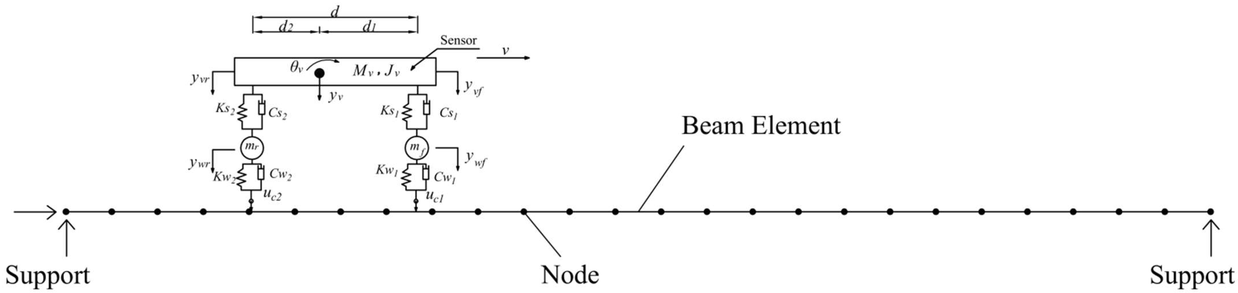
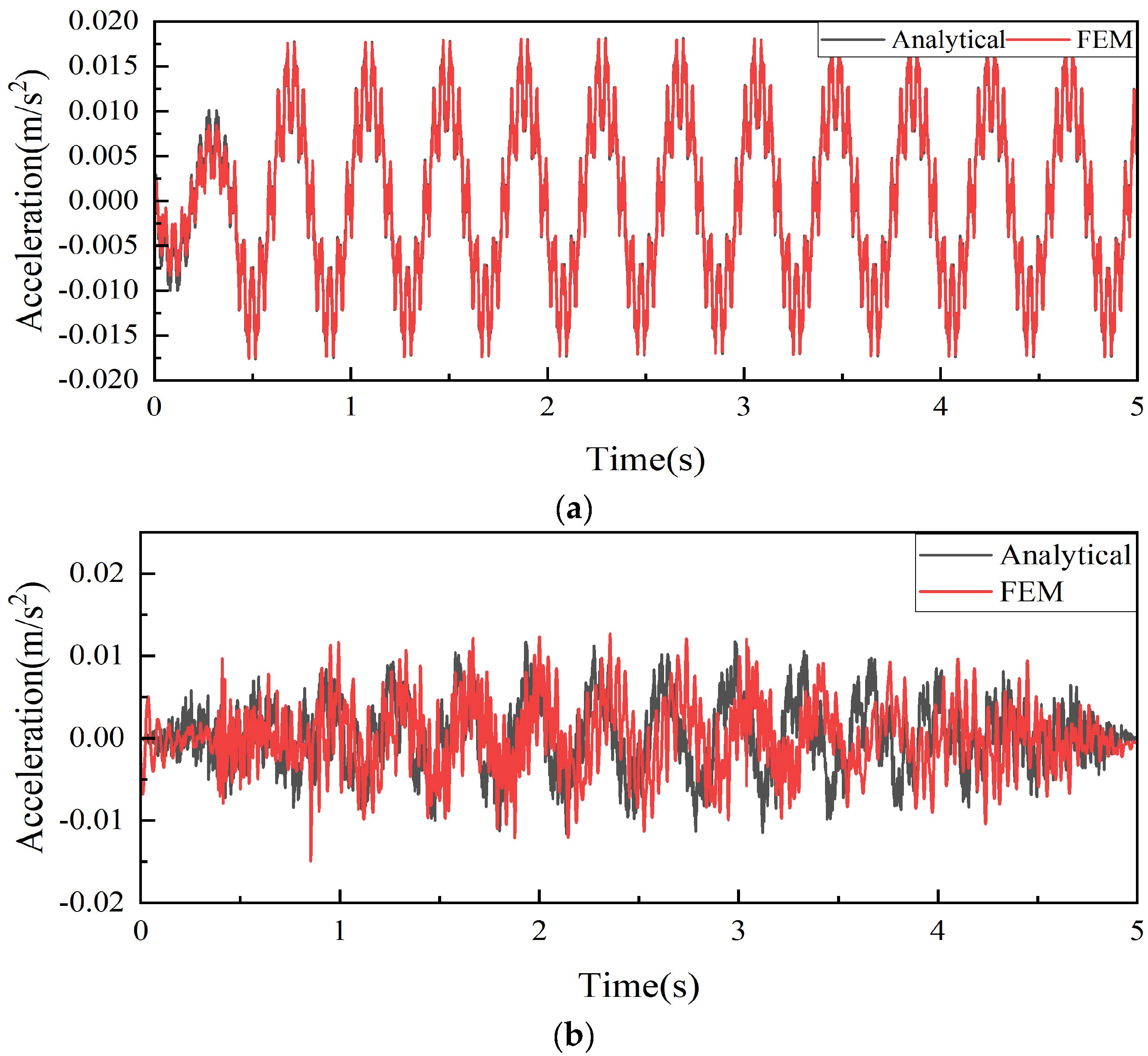
2.1. Vehicle–Bridge Coupling Analysis

Closed-Form Solutions for Contact Point Responses

Figure 1 illustrates the vehicle–bridge interaction element for the two-axle vehicle employed in this study. The vehicle travels at a speed v over a simply supported beam. It is modeled as a two-axle system with four degrees of freedom, comprising the vehicle body mass Mv and wheel mass mr and mf. The vertical translation is denoted as yv. The contact point response is denoted as uc. The simply supported beam is considered a Euler beam. The span length of the simply supported beam is L, the mass per unit length is m, and the flexural rigidity is EI. To simplify the calculations, the theoretical derivation does not consider pavement roughness.
The bridge displacement response can be written as [24]:
u x , t = n = 1 N i = 1 , 2 Δ s t n , i 1 S n 2 sin n π ν t t i L S n sin ω b , n t t i H t t i H t t i T sin n π x L .
And the contact point response displacement can be written as:
u c j t = n = 1 N i = 1 , 2 Δ s n , i 1 S n 2 sin n π ν t t i L S n sin ω b , n t t i H t t i H t t i T sin n π ν t t j L , j = 1 , 2 .
where Δstn is the n-th modal static deflection, Sn is the speed parameter, ωbn is the nth bridge frequency, and Pj is the axle loads, and the expressions for the parameters are as follows:
Δ s t n , j = 2 p j L 3 E I n 4 π 4 , S n = n π v L ω b n , ω b n = n 2 π 2 L 2 E I m , p j = d d j m v g d , t j = j 1 d v , T = L v ,

2.2. Damage Identification Based on Continuous Wavelet Transform

2.2.1. Brief on Continuous Wavelet Transform

The wavelet transform is a versatile signal processing technique extensively applied in bridge health monitoring and damage detection. Applying wavelet transform can decompose a signal into components at different scales and time locations, allowing for a more precise analysis of the signal’s local features. Common wavelet transform techniques include the discrete wavelet transform (DWT) and continuous wavelet transform (CWT). Frequently used wavelet basis functions comprise the Haar, Morlet, Mexican hat, and Daubechies wavelets. In this study, the continuous wavelet transform employing the Mexican hat wavelet was utilized to analyze the acceleration response of the vehicle–bridge system, as detailed in [25]:
W T f ( a , b ) = 1 a 0 f ( t ) ψ t b a d t
ψ a , b ( t ) = ( 1 t 2 ) e t 2 / 2
where f (t) represents the signal—in this study, the acceleration response; ψ a , b ( t ) is the Mexican hat wavelet function; ψ ( t ) is the complex conjugate of the mother wavelet; t is the time variable; a is the dilation or scale parameter that controls the wavelet’s stretching; and b is the translation (or shift) parameter that controls the wavelet’s position in time.

2.2.2. Selection of Wavelet Basis Functions and Wavelet Scales

Different wavelet basis functions can lead to varying analytical results when using continuous wavelet transform to analyze acceleration time series signals. Choosing an appropriate wavelet basis function according to the specific processing goals can achieve optimal results. Commonly employed wavelet basis functions include the Haar, Morlet, Mexican hat, and Daubechies wavelets. This study preliminarily analyzed the effectiveness of different wavelet basis functions for damage identification. The results showed that the Mexican hat wavelet performed best among the selected wavelet basis functions and thus was chosen for subsequent analysis.
The relationship between wavelet scale and pseudo-frequency can be expressed by the following equation:
S c a l e = F s F c / f a
where Scale represents the scale range for calculating wavelet coefficients, Fs is the signal sampling frequency, Fc is the wavelet center frequency, and fa is the frequency corresponding to scale a.

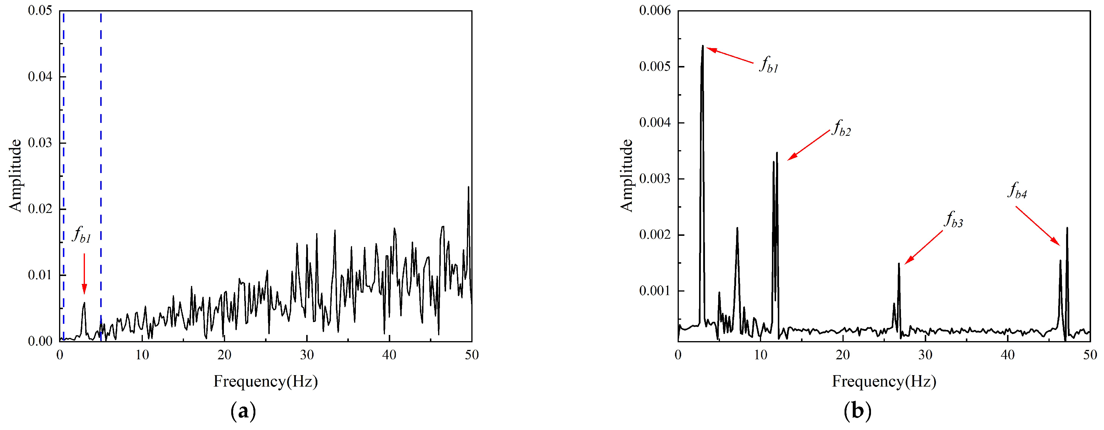
2.2.3. Brief on Variational Modal Decomposition

As previously mentioned, the acceleration response of the test vehicle contains multiple components of bridge vibrations, adversely affecting the accuracy of damage identification. To improve the identification accuracy, this study employs the variational mode decomposition method to decompose the vibration data of the test vehicle, thereby clearly identifying the characteristic information of each bridge mode for effective damage identification.
Variational mode decomposition is capable of decomposing complex signals into multiple intrinsic mode functions, each characterized by distinct frequency ranges and waveform patterns. In variational modal decomposition, the signal is decomposed into several intrinsic mode functions (IMFs). Variational modal decomposition obtains these modal functions by solving a variational problem, unlike other modal decomposition methods. Its main advantage lies in decomposing the signal into modes with stricter bandwidth limitations and gradually reducing residuals. At the same time, variational modal decomposition allows the bandwidth width to be adjusted according to needs during the decomposition process. Compared with empirical mode decomposition (EMD), variational modal decomposition shows significant advantages. First, variational modal decomposition has higher robustness to noise and can effectively separate the intrinsic modes of the signal, while EMD tends to generate spurious modes under high noise conditions. Second, the decomposition results of variational modal decomposition are more stable as it optimizes each mode’s center frequency and bandwidth based on the variational principle. In contrast, EMD results are more susceptible to data starting points, leading to endpoint effects and mode mixing. Finally, variational modal decomposition is based on the variational principle and has a more rigorous mathematical derivation process, whereas EMD mainly relies on empirical rules, lacking a solid theoretical foundation.
The foundation of variational mode decomposition (VMD) lies in formulating a variational optimization problem. This approach leverages principles from classical Wiener filtering, the Hilbert transform, and frequency mixing to decompose multi-component signals into intrinsic mode functions (IMFs). During the decomposition, it is assumed that the sum of the component signals reconstructs the original signal. The method then iteratively searches for IMFs with limited bandwidths and optimally matched center frequencies to minimize the total bandwidth sum. This approach determines the number of IMFs and can control the number of output IMFs based on actual conditions. Each IMF can be represented as:
U k = A k ( t ) cos φ k ( t )
where Ak (t) is the instantaneous amplitude of Uk; φk (t) is the instantaneous phase; and t is time.
The corresponding expression for the constrained optimization problem constructed by variational modal decomposition for the component signals is:
f ( t ) = k u k ( t )
where f(t) is the original signal, K is the total number of modes, and uk(t) is the k-th mode function.
min { u k } , { ω k } k t δ t + i π t u k t e i ω k t 2 2
where {uk} represents the set of decomposed mode functions, {ωk} is the set of center frequencies for each mode function, δ(t) is the Dirac delta function, * denotes convolution, and i is the imaginary unit.
The unconstrained optimization problem is formulated using the extended Lagrangian expression L as follows:
L ( U k , ω k , λ ) = α k t δ ( t ) + j π t u k ( t ) e j w k t 2 2 + f ( t ) k u k ( t ) 2 2 + λ ( t ) , f ( t ) k u k ( t )
The alternating direction method of multipliers is used to iteratively update the intrinsic mode parameters and center frequencies until the optimal solution of the above function is obtained. The steps for solving the variational problem using variational modal decomposition are as follows: initialize { u k 1 } , { ω k 1 } , λ 1 , and n to zero and iteratively update using the expressions. In this study, α is set to 3000.
u ^ k ( n + 1 ) ( ω ) = f ^ ( ω ) i k u ^ i ( ω ) + λ ^ ( ω ) 2 1 + 2 α ( ω ω k )
In the formula, ω k ( n + 1 ) update iteratively according to Expression (11).
ω k ( n + 1 ) = 0 ω u ^ k ( ω ) 2 d ω 0 u ^ k ( ω ) 2 d ω
For λ n + 1 , update iteratively according to Expression (12).
λ n + 1 = λ n + τ ( f k u k n + 1 )
Iterate through Expressions (10) to (13) until the convergence condition shown in Expression (14) is met.
k u ^ k n + 1 u ^ k n 2 2 u ^ k n 2 2 < ε
In the formula, ε is the preset threshold, typically set to 1 × 10⁻⁷. The iteration ends when the entire update procedure meets the condition specified in Expression (14).

3. Numerical Verification

3.1. VBI Design of Simply Supported Bridges

Bridge and vehicle parameters in finite element simulations are derived from [26]. The bridge’s total length is 25 m and is divided into 25 elements of 1 m each. The damage of the bridge is simulated by reducing the element stiffness EI, and the degree of damage is noted as δ. The time step for the VBI analysis is established at 0.001 s. Additionally, the vehicle speed is fixed at 5 m/s, with the parameters of the vehicle and bridge system being detailed in Table 1. The VBI is executed using a self-developed Abaqus program. The first three natural frequencies of the bridge are identified as 2.97, 11.80, and 25.99 Hz, respectively. Figure 2 shows the analytical and FEM acceleration response of the bridge mid-span and front axle contact point response.
A total of nine damage scenarios were considered, as shown in Table 2. In Cases 1–4, the damage was assumed to be located at the 13th element at mid-span, with varying degrees of severity: 5%,10%, 20%, and 30%. In Case 5, the speed was reduced from 5 m/s to 2 m/s and the speed was increased from 5 m/s to 8 m/s in Case 6 to study the impact of vehicle speed further. And in Case 7, we investigated the effect of multiple damages and the damage severity in Elements 7, 13, and 18 was 30%. And in Cases 8 and 9, we investigate the effect of bridge span size on damage identification, and damage cases for two- and three-span girders are arranged.

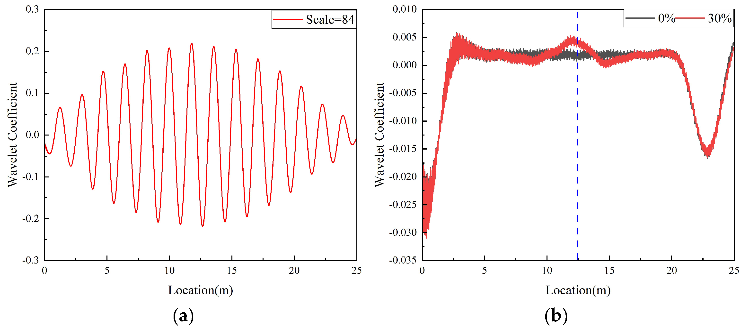
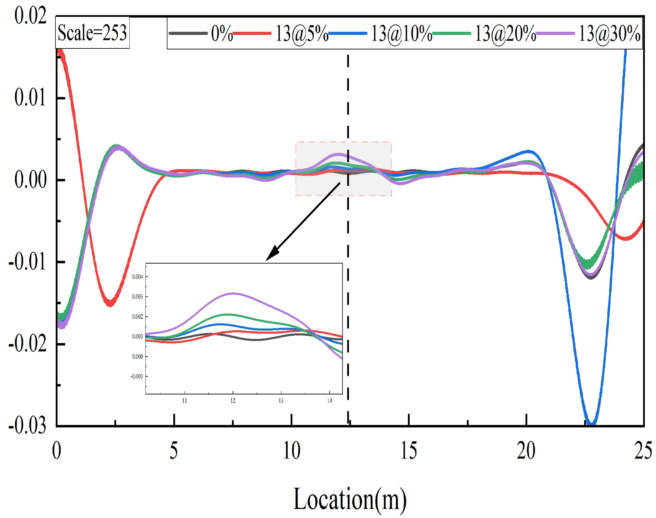
3.2. Damage Identification Based on Continuous Wavelet Transform

Previous studies have shown that when a structure is damaged, its response exhibits local singularities. Time–frequency domain methods, represented by continuous wavelet transform [27,28,29,30,31], do not rely on the bridge response under healthy conditions, thus having broad practical value. By applying wavelet transform to the local singularities of structural responses at appropriate scale factors, variations in wavelet coefficients can be observed, enabling effective identification of bridge damage. The central frequency of the Mexican hat wavelet is 0.25 Hz, and the sampling frequency in the numerical simulation is 1000 Hz. According to Equation (6), the wavelet scale corresponding to the structural fundamental frequency is Scale = 84. Figure 3a shows the wavelet coefficient plot obtained by applying continuous wavelet transform to the acceleration response of the contact point in Case 3. The vertical axis in the figure represents the continuous wavelet transform wavelet coefficients, and the horizontal axis is the relative position of the bridge. At the wavelet scale corresponding to the fundamental frequency, the vibration mode of the bridge structure can be effectively reflected. Still, the damage location cannot be determined across the entire time domain. The wavelet coefficients of the contact point acceleration response at three times the fundamental scale were further extracted to locate the damage. Figure 3b shows the WC map for a scale factor of three times the fundamental scale (Scale = 253) in Case 3, and for comparison, a WC map of the undamaged bridge is also shown. As shown in Figure 3b, although the acceleration values at the damaged location show a certain upward trend, this trend is not very pronounced as the overall trend of WC is significantly disrupted by its fluctuations, especially those with high-frequency content.

3.3. Damage Identification Based on Variational Modal Decomposition–Continuous Wavelet Transform

The previous discussion indicates that applying continuous wavelet transform to contact point acceleration response results in poor WC detection performance, mainly due to the contamination of high-frequency components in WC. To improve identification accuracy, it is necessary to filter the contact point response to make the WC trend more distinct. Therefore, this paper first applies variational mode decomposition to analyze the acceleration response of the contact point, decomposing the extracted acceleration signal into a series of intrinsic mode functions (IMFs) with different frequencies. Figure 4 shows the IMFs and the corresponding FFT spectra after processing the acceleration response (Case 4). Figure 4a shows the driving frequency component response and the first three components of the bridge response under variational mode decomposition, while Figure 4b presents the corresponding frequency spectra.
The continuous wavelet transform results of the contact point response for Cases 1–4 are shown in Figure 5. As seen in Figure 5, after applying the variational mode decomposition technique, the continuous wavelet transform images become smoother, with more pronounced bulges at the bridge damage locations, which become more significant as the damage severity increases. This indicates that the variational modal decomposition–continuous wavelet transform can be used to detect the damage location and quantify the severity of the beam damage.
The steps of damage identification in this study are as follows:
(1)
The test vehicle drives over the bridge at speed v, and the data are collected by the acceleration sensor on the test vehicle;
(2)
Obtain the contact point acceleration response by calculation;
(3)
Decompose the contact point acceleration response by variational modal decomposition transformation to obtain a number of IMFs.
(4)
Extract the IMFs corresponding to the first-order intrinsic frequency of the bridge, and use continuous wavelet transform for damage identification.

3.4. Multiple Damage Identification

This section will further discuss its performance in multiple damage scenarios. One multiple damage scenario is discussed. In Case 7, Elements 7, 13, and 18 experience damage levels of 30%, respectively. Figure 6 examines the variational modal decomposition–continuous wavelet transform derived from the contact point acceleration. As shown in Figure 6, three distinct peaks are evident at the damaged locations. The finding suggest that the variational modal decomposition–continuous wavelet transform extracted from contact point acceleration is effective for identifying damage across multiple damage scenarios.

4. Parameter Discussion

In this section, we will examine the influence of various parameters on the effectiveness of the proposed damage identification method, including vehicle speed, scale factor, number of bridge spans, and pavement roughness.

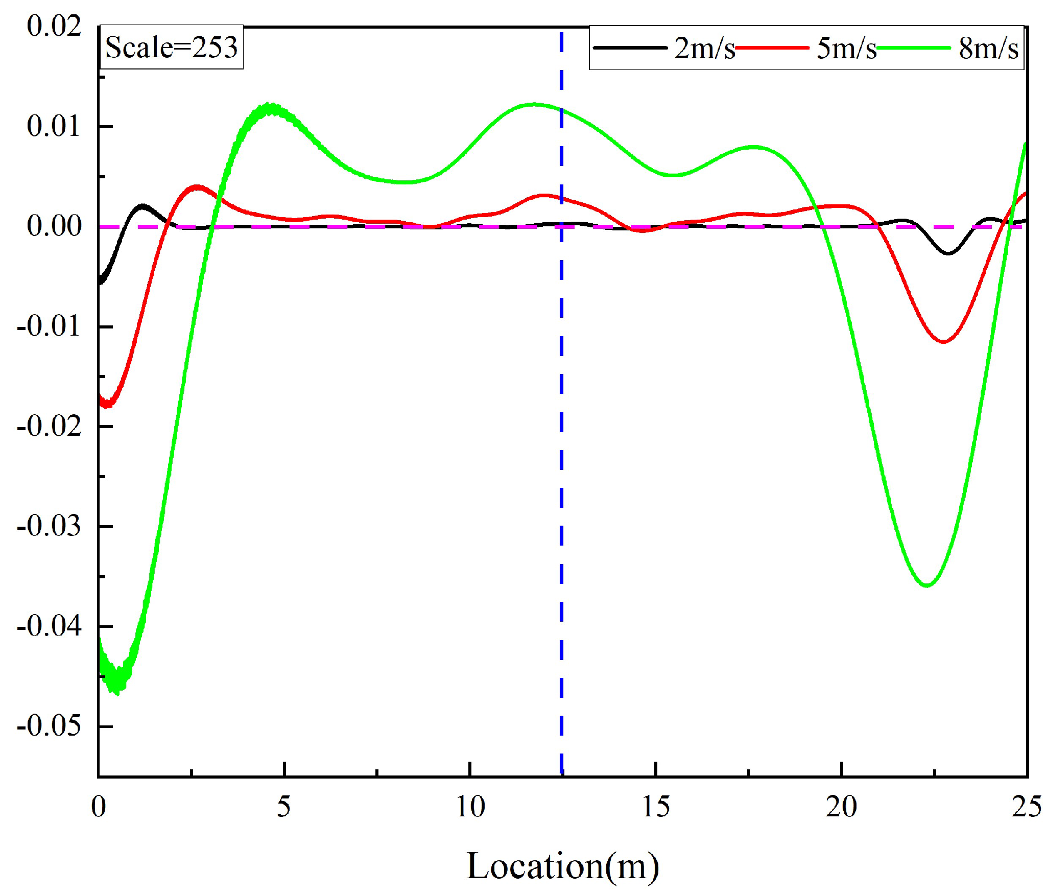
4.1. Effect of Vehicle Speed

This section examines the performance of the proposed bridge damage identification method in Cases 4–6 under vehicle speeds of 2 m/s, 5 m/s, and 8 m/s. As shown in Figure 7, the process can effectively identify the damage location at all three vehicle speeds. As the vehicle speed increases, the peak at the damage location also gradually increases. This is because increased vehicle speed enhances the vehicle–bridge vibration response, making the damage more apparent. However, when the speed of the vehicle is too fast, on the one hand, the effective data collected is reduced, which is detrimental to damage recognition. On the other hand, the interference from the pavement roughness is also exacerbated. Therefore, the vehicle speed should be maintained within a reasonable range to optimize the damage identification effect.

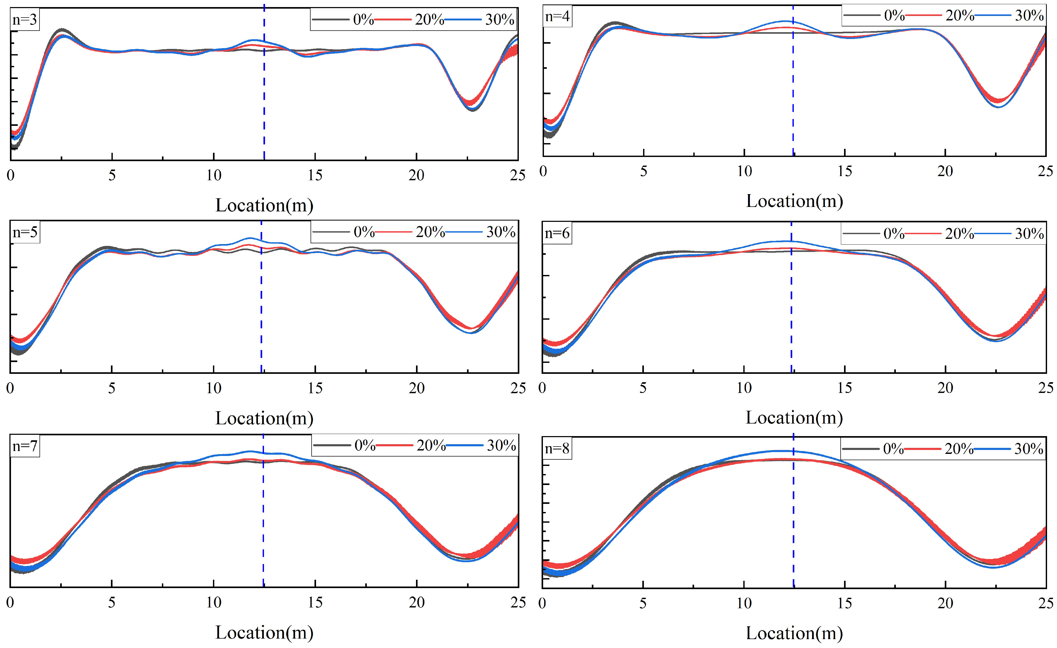
4.2. Effect of Scale Factor

As previously mentioned, the continuous wavelet transform’s scale factor significantly impacts the effectiveness of the proposed damage detection method. In practical applications, the optimal scale factor is usually determined through trial and error and adjustments. Taking Case 3–4 as an example, the basic wavelet scale factor corresponding to the contact point acceleration response was determined to be Scale = 84 using the Mexican hat wavelet. Then, based on this basic scale, the continuous wavelet transform signals of n times the basic scale were examined. Figure 8 shows the variational modal decomposition–continuous wavelet transform within the range of n = 3–8 times the basic scale. The figure shows that the wavelet scales of 3–7 times the basic scale can effectively identify the damage location. Moreover, as the scale increases, the influence of the wavelet boundary effect gradually increases, and the length that can be recognized will gradually decrease, so the appropriate wavelet scale should be selected for damage recognition according to the actual situation in practical use.

4.3. Effect of Number of Bridge Spans

In the above analyses, only single-span simply supported beams have been considered. Through the above discussion, using variational modal decomposition–continuous wavelet transform method is effective for the damage identification of simply supported beams. And in reality, it is mostly continuous bridges. Therefore, in this section, two-span and three-span beams will be investigated to verify the effectiveness of the proposed method for continuous bridges, assuming that the length of each span is equal to that of a single span. A two-span bridge is considered in Case 8, where Element 7 and Element 13 of the first span experience damage levels of 30%, respectively, and Element 38 of the second span experience damage levels of 30%. Figure 9a shows the damage identification results for the Scale = 253. From the figure, it can be seen that there is a clear prominent peak at the positions of Element 7, 13, and 38. In Case 9, three span bridges are considered, where Element 13 of the first span experience damage levels of 30%, Element 32, Element 38, and Element 44 of the second span experience damage levels of 20%, 15%, and 20% respectively, and Element 63 of the third span experience damage levels of 30%. Figure 9b shows the damage identification results for the Scale = 253. It can be seen from the figure that there are distinct prominent peaks at the positions of Element 13, Element 32, Element 38, Element 44, and Element 63. Case 8 and Case 9 show that the method using variational modal decomposition–continuous wavelet transform is also effective for damage identification in continuous beams.

4.4. Effect of Pavement Roughness

In reality, bridge surfaces often have a certain degree of roughness, enhancing the bridge’s excitation of the vehicle and masking the bridge frequency in the vehicle spectrum. In this section, we consider the impact of A-grade road surface roughness described in [32] and obtained the contact point response spectrum, as shown in Figure 10a. The results indicate that even under A-grade road surface roughness, the contact point response spectrum still clearly shows the first bridge frequency, but higher bridge frequencies are obscured. In addition, we can also use the residual response of the front and rear contact points to reduce the effect of road surface roughness. The contact residual response is shown in Figure 10b.

5. Conclusions

Bridge damage identification generally encompasses several essential steps: damage detection, localization, classification, and severity assessment and overall structural performance prediction. This study primarily concentrates on two fundamental aspects—damage detection (determining whether damage exists) and damage localization (identifying the location of damage)—while also exploring the evaluation of damage severity and the method’s effectiveness in scenarios involving multiple damage sites. This study introduces a damage identification index that integrates contact point acceleration responses with continuous wavelet transform analysis, aiming to achieve effective and accurate bridge damage detection. The study first derived the equations for the contact point response of the vehicle–bridge coupled vibration system. It validated the feasibility of using the damage index in identifying bridge damage using the contact point response. Based on a theoretical analysis and numerical simulations, the following conclusions can be drawn:
(1)
The variational mode decomposition technique helps separate different frequency components in the contact point acceleration response, eliminating modal aliasing and spurious frequency issues. This improves the accuracy and stability of damage identification.
(2)
Studies show that within a certain range, the effectiveness of damage identification improves with increased vehicle speed. However, bridge deck roughness may affect excessively high speeds, interfering with identification results.
(3)
Using the continuous wavelet transform to process the contact point acceleration response can extract bridge damage features effectively. The effective scale factor range of the continuous wavelet transform coefficients extracted by this method is broad, and adjusting the scale factor can further improve the accuracy of damage location identification.
(4)
The proposed variational modal decomposition–continuous wavelet transform method is not only applicable for the identification of damage in simply supported beams but also for the identification of damage in continuous beams.
(5)
Even when considering road surface roughness, the proposed damage identification method can still accurately identify damage locations, demonstrating its potential for practical application under complex conditions.
It is important to note that this research focuses on immediate damage detection and localization and does not extend to long-term predictions of structural performance degradation or remaining service life based on the identification outcomes. However, this research direction has substantial engineering significance and will form a central part of future work. Upcoming studies will aim to integrate detection data with machine learning techniques to develop predictive models for bridge performance degradation, thereby enabling a more comprehensive approach to structural health assessment and life-cycle prediction. Additionally, current research on the vehicle scanning method primarily focuses on theoretical derivation and numerical simulation. More field bridge tests should be conducted to promote the practical application of the vehicle scanning method. This will validate the effectiveness of the theoretical research and provide practical data support for the improvement and optimization of the method, thereby promoting the widespread application of the vehicle scanning method in bridge health diagnostics. Recent applications of and investigations into the vehicle scanning method are predominantly concentrated on conventional medium- and short-span bridges, such as simply supported and continuous girder bridges. In contrast, research on large-span flexible structures—such as cable-stayed and suspension bridges—remains in an early exploratory phase, with limited studies available in the literature. This research gap primarily arises from the unique challenges posed by the complex structural configurations and dynamic behaviors of long-span bridges, which complicate the application of vehicle scanning method techniques. Despite these challenges, the vehicle scanning method holds considerable promise for monitoring the health of long-span bridges due to its distinctive advantages: (1) it does not require traffic interruption, (2) allows for the flexible deployment of sensing equipment, (3) entails relatively low monitoring costs, and (4) offers strong repeatability. These features make it particularly suitable for complex structural systems exhibiting significant nonlinearities—such as cable-stayed and suspension bridges—as well as for critical infrastructure with high safety and operational continuity requirements, including railway bridges. In such contexts, the vehicle scanning method may serve as an efficient and cost-effective tool for long-term structural health monitoring.

Author Contributions

X.J.: Conceptualization, methodology, software, investigation, formal analysis, writing—original draft; K.M.: conceptualization, funding acquisition, resources, supervision, writing—review and editing; J.W.: conceptualization, methodology, formal analysis, writing—review and editing; Z.L.: resources, writing—review and editing. All authors have read and agreed to the published version of the manuscript.

Funding

This research was funded by the Yunnan Key Laboratory of Structural Health Diagnosis for Colleges and Universities (KKKP201207003).

Data Availability Statement

All data, models, or codes that support the findings of this study are available upon reasonable request.

Conflicts of Interest

The authors declare no conflicts of interest.

References

  1. Ren, W.X.; Zhao, T.; Harik, I.E. Experimental and Analytical Modal Analysis of Steel Arch Bridge. J. Struct. Eng. 2004, 130, 1022–1031. [Google Scholar] [CrossRef]
  2. Kim, C.W.; Chang, K.C.; Kitauchi, S.; McGetrick, P.J. A field experiment on a steel Gerber-truss bridge for damage detection utilizing vehicle-induced vibrations. Struct. Health Monit. 2016, 15, 421–429. [Google Scholar] [CrossRef]
  3. Bayissa, W.L.; Haritos, N.; Thelandersson, S. Vibration-based structural damage identification using wavelet transform. Mech. Syst. Signal Process. 2008, 22, 1194–1215. [Google Scholar] [CrossRef]
  4. Amezquita-Sanchez, J.P.; Adeli, H. Signal Processing Techniques for Vibration-Based Health Monitoring of Smart Structures. Arch. Comput. Methods Eng. State Art Rev. 2016, 23, 1–15. [Google Scholar] [CrossRef]
  5. Yang, Y.B.; Wang, Z.-L.; Shi, K.; Xu, H.; Wu, Y.T. State-of-the-Art of the Vehicle-Based Methods for Detecting the Various Properties of Highway Bridges and Railway Tracks. Int. J. Struct. Stab. Dyn. 2020, 20, 2041004. [Google Scholar] [CrossRef]
  6. Yang, Y.B.; Lin, C.W.; Yau, J.D. Extracting bridge frequencies from the dynamic response of a passing vehicle. J. Sound Vib. 2004, 272, 471–493. [Google Scholar] [CrossRef]
  7. Lin, C.W.; Yang, Y.B. Use of a passing vehicle to scan the fundamental bridge frequencies: An experimental verification. Eng. Struct. 2005, 27, 1865–1878. [Google Scholar] [CrossRef]
  8. Curadelli, R.O.; Riera, J.D.; Ambrosini, D.; Amani, M.G. Damage detection by means of structural damping identification. Eng. Struct. 2008, 30, 3497–3504. [Google Scholar] [CrossRef]
  9. Garbowski, T.; Cornaggia, A.; Zaborowicz, M.; Sowa, S. Computer-Aided Structural Diagnosis of Bridges Using Combinations of Static and Dynamic Tests: A Preliminary Investigation. Materials 2023, 16, 7512. [Google Scholar] [CrossRef]
  10. Shirzad-Ghaleroudkhani, N.; Gül, M. Inverse Filtering for Frequency Identification of Bridges Using Smartphones in Passing Vehicles: Fundamental Developments and Laboratory Verifications. Sensors 2020, 20, 1190. [Google Scholar] [CrossRef]
  11. Yang, Y.; Zhu, Y.; Wang, L.L.; Jia, B.Y.; Jin, R. Structural Damage Identification of Bridges from Passing Test Vehicles. Sensors 2018, 18, 4035. [Google Scholar] [CrossRef] [PubMed]
  12. Chang, K.C.; Kim, C.W. Modal-parameter identification and vibration-based damage detection of a damaged steel truss bridge. Eng. Struct. 2016, 122, 156–173. [Google Scholar] [CrossRef]
  13. Locke, W.; Sybrandt, J.; Redmond, L.; Safro, I.; Atamturktur, S. Using drive-by health monitoring to detect bridge damage considering environmental and operational effects. J. Sound Vib. 2020, 468, 115088. [Google Scholar] [CrossRef]
  14. Obrien, E.J.; Malekjafarian, A.; González, A. Application of empirical mode decomposition to drive-by bridge damage detection. Eur. J. Mech. A/Solids 2017, 61, 151–163. [Google Scholar] [CrossRef]
  15. Tan, C.; Elhattab, A.; Uddin, N. Wavelet-Entropy Approach for Detection of Bridge Damages Using Direct and Indirect Bridge Records. J. Infrastruct. Syst. 2020, 26, 04020037. [Google Scholar] [CrossRef]
  16. Cornaggia, A.; Ferrari, R.; Zola, M.; Rizzi, E.; Gentile, C. Signal Processing Methodology of Response Data from a Historical Arch Bridge toward Reliable Modal Identification. Infrastructures 2022, 7, 74. [Google Scholar] [CrossRef]
  17. Demirlioglu, K.; Erduran, E. Drive-by Bridge Damage Detection Using Continuous Wavelet Transform. Appl. Sci. 2024, 14, 2969. [Google Scholar] [CrossRef]
  18. Liu, J.-L.; Wang, S.-F.; Li, Y.-Z.; Yu, A.-H. Time-varying damage detection in beam structures using variational mode decomposition and continuous wavelet transform. Constr. Build. Mater. 2024, 411, 134416. [Google Scholar] [CrossRef]
  19. Dindar, P.; Hosseini, M.; Mansoori, M.R. Modal Data Identification of the Prestressed Concrete Bridge Using Variational Mode Decomposition. Amirkabir J. Civ. Eng. 2022, 54, 715–736. [Google Scholar] [CrossRef]
  20. Wu, Z.; Huang, N.E. Ensemble empirical mode decomposition: A noise-assisted data analysis method. Adv. Adapt. Data Anal. 2011, 1. [Google Scholar] [CrossRef]
  21. Rilling, G.; Flandrin, P.; Goncalves, P. On empirical mode decomposition and its algorithms. In Proceedings of the IEEE-EURASIP Workshop on Nonlinear Signal and Image Processing, NSIP-03, Grado, Italy, 8–11 June 2003. [Google Scholar]
  22. Yeh, J.R.; Shieh, J.S.; Huang, N.E. Complementary Ensemble Empirical Mode Decomposition: A Novel Noise Enhanced Data Analysis Method. Adv. Adapt. Data Anal. 2010, 2, 135–156. [Google Scholar] [CrossRef]
  23. Yang, Y.B.; Zhang, B.; Qian, Y.; Wu, Y. Further Revelation on Damage Detection by IAS Computed from the Contact-Point Response of a Moving Vehicle. Int. J. Struct. Stab. Dyn. 2018, 18, 1850137. [Google Scholar] [CrossRef]
  24. Yang, Y.B.; Xu, H.; Wang, Z.; Shi, K. Using vehicle–bridge contact spectra and residue to scan bridge’s modal properties with vehicle frequencies and road roughness eliminated. Struct. Control Health Monit. 2022, 29, e2968. [Google Scholar] [CrossRef]
  25. Chui, C.K. An Introduction to Wavelets. Comput. Phys. 1992, 2, 50–61. [Google Scholar] [CrossRef]
  26. Xu, H.; Liu, Y.; Yang, M.; Yang, D.; Yang, Y. Mode shape construction for bridges from contact responses of a two-axle test vehicle by wavelet transform. Mech. Syst. Signal Process. 2023, 195, 110304. [Google Scholar] [CrossRef]
  27. Gentile, A.; Messina, A. On the continuous wavelet transforms applied to discrete vibrational data for detecting open cracks in damaged beams. Int. J. Solids Struct. 2003, 40, 295–315. [Google Scholar] [CrossRef]
  28. Zhong, S.; Oyadiji, S.O. Detection of cracks in simply-supported beams by continuous wavelet transform of reconstructed modal data. Comput. Struct. 2011, 89, 127–148. [Google Scholar] [CrossRef]
  29. Xiang, J.; Liang, M. Multiple damage detection method for beams based on multi-scale elements using Hermite cubic spline wavelet. Discret. Optim. 2011, 73, 23–39. [Google Scholar] [CrossRef]
  30. Hester, D.; González, A. A wavelet-based damage detection algorithm based on bridge acceleration response to a vehicle. Mech. Syst. Signal Process. 2012, 28, 145–166. [Google Scholar] [CrossRef]
  31. Ulker-Kaustell, M.; Karoumi, R. Application of the continuous wavelet transform on the free vibrations of a steel–concrete composite railway bridge. Eng. Struct. 2011, 33, 911–919. [Google Scholar] [CrossRef]
  32. ISO 8608; Mechanical Vibration-road Surface Profiles-Reporting of Measured Data. International Organization for Standardization: Geneva, Switzerland, 1995.
Figure 1. Vehicle–bridge interaction element for a two-axle vehicle.
Applsci 15 06682 g001
Figure 2. The dynamic response of the vehicle–bridge system: (a) bridge mid-span acceleration; (b) front axle contact point acceleration.
Applsci 15 06682 g002
Figure 3. Continuous wavelet transform of contact point acceleration in Case 3: (a) wavelet coefficient plot at fundamental scale; (b) wavelet coefficient plot at scale = 253.
Applsci 15 06682 g003
Figure 4. IMFs and FFT Extracted by variational modal decomposition: (a) IMFs; (b) FFT.
Applsci 15 06682 g004
Figure 5. Continuous wavelet transform of contact point response in Cases 1–4.
Applsci 15 06682 g005
Figure 6. Multiple damage scenarios (@ indicates damage level).
Applsci 15 06682 g006
Figure 7. Variational modal decomposition–continuous wavelet transform at different vehicle speeds.
Applsci 15 06682 g007
Figure 8. Wavelet coefficients at n times the basic scale.
Applsci 15 06682 g008
Figure 9. Variational modal decomposition–continuous wavelet transform with different numbers of spans.
Applsci 15 06682 g009
Figure 10. Effect of pavement roughness: (a) the contact point response spectrum; (b) contact residual response under A-grade road surface roughness.
Applsci 15 06682 g010
Table 1. Vehicle and bridge parameters.
Vehicle body


Wheel
Mass (kg)
Mass moment of inertia (kg.m2)
Stiffness (kN/m)
Damping coefficient (kN·s/m)
Axle distance to gravity center(m)
Vehicle speed (m/s)
Mass (kg)
Wheel stiffness (kN/m)
Wheel damping (Kn·s/m)
Mv = 1000
Jv = 500
Ks1 = Ks2 = 500
Cs1 = Cs2 = 1
d1 = 0.9, d2 = 1.1
v = 5
mf = mr = 100
Kw1 = Kw2 = 1000
Cw1 = Cw2 = 1
BridgeBridge Span (m)
Modulus of elasticity (GPa)
Cross-sectional moment of inertia (m4)
Mass per unit length (kg/m)
L = 25
E = 27.5
I = 0.12
m = 2400
Table 2. Case setup for VBI analysis.
Case
Number
Vehicle Mass
(kg)
Vehicle Speed
(m/s)
Damage Location
(Element Number)
Degree of Damage
(%)
110005135
2100051310
3100051320
4100051330
5100021330
6100081330
7100057, 13, 1830
8100057, 13, 3830
91000513, 32, 38, 44, 6330, 20, 15, 20, 30
Disclaimer/Publisher’s Note: The statements, opinions and data contained in all publications are solely those of the individual author(s) and contributor(s) and not of MDPI and/or the editor(s). MDPI and/or the editor(s) disclaim responsibility for any injury to people or property resulting from any ideas, methods, instructions or products referred to in the content.

