Featured Application
The uncooled coaxial insulated monopole antenna investigated in this study will be used for dual-mode operation, enabling tissue ablation and real-time scattering parameter measurement. Its simple and reproducible monopole design can be used to investigate temperature-dependent dielectric properties for microwave ablation. This research serves as a precursor study, addressing the structural challenges posed by PTFE expansion due to temperature variations during ablation and proposing coaxial annealing as a solution to mitigate these effects. By enhancing the antenna’s thermal resilience, the proposed method ensures stable performance and improves lesion shape, contributing to a more optimised dual-mode ablation procedure.
Abstract
There is growing interest in measuring the temperature-dependent dielectric properties of bio-tissues using dual-mode techniques (scattering measurements and thermal treatment). Uncooled coaxial antennas are preferred for their direct contact with the measured medium and reduced complexity; however, they exhibit structural changes during ablation due to the thermal expansion of polytetrafluoroethylene (PTFE). This paper presents an experimental study on PTFE expansion in an uncooled coaxial insulated monopole antenna in response to changes in the tissue’s thermal environment. Furthermore, it presents a methodology to mitigate these effects through coaxial annealing. The investigation consists of two distinct experiments: characterising PTFE expansion and assessing the effects of annealing through microwave ablation. This was achieved by simulating the thermal effects experienced during ablation by immersing the test antenna in heated peanut oil. PTFE expansion was measured through camera monitoring and using a toolmaker’s microscope, revealing two expansion modalities: linear PTFE expansion and non-linear plastic deformation from manufacturing processes. The return loss during ablation and consequential changes in the ablated lesion were also assessed. Antenna pre-annealing increased resilience against structural changes in the antenna, improving lesion ellipticity. Therefore, this study establishes a fabrication method for achieving an uncooled thermally stable antenna, leading to an optimised dual-mode ablation procedure, enabling quasi-real-time permittivity measurement of the surrounding tissue.
1. Introduction
Microwave tumour ablation is a percutaneous cancer treatment. The treatment consists of a needle-like applicator being inserted through the skin and guided to a target tumour using medical imaging systems. Microwave energy irradiated from the applicator’s end tip into the surrounding tumorous tissue elevates the temperature to over 100 °C, causing immediate cellular death [1,2,3]. The microwave energy is irradiated by a microwave antenna inside the applicator, which is either uncooled or actively cooled with circulated chilled saline water or CO2 [4,5,6,7,8,9,10].
The surrounding tissue undergoes mechanical and electrical changes during ablation treatment due to the sharp rise in temperature. Since the dielectric properties of biological tissue are frequency-dependent and temperature-dependent, numerous studies have been conducted to measure dielectric properties in various tissues, mainly using techniques such as open-ended coaxial reflection and resonant cavities [11,12,13,14]. However, the main disadvantages of these techniques are the small sensing volume of the open-ended coaxial probe [15] and the destruction/manipulation of the material under test by resonant cavity techniques [14]. Moreover, the heating methods employed (thermal bath, microwave oven, and supplementary ablator, amongst others) might be limiting, as they do not accurately emulate the thermal environment induced through ablation due to different heat deposition rates and water mobility [16,17,18]. Hence, there is increasing interest in investigating the transient effects of heat deposition rates in tissue with dual-mode applications. This approach utilises the same ablation antenna for both treatment and quasi-simultaneous measurement of the scattering parameters, which can be transformed into the dielectric properties of the surrounding tissue [19,20,21]. Existing conversion models, initially developed for open-ended coaxial probe measurement techniques [22,23,24], are typically adapted for the specific applicator used in the ablation procedure. These models facilitate the conversion of measured scattering parameters into complex permittivity values by characterising the antenna’s electromagnetic behaviour using reference liquids with well-defined dielectric properties. Once calibrated, the quasi-real-time scattering parameters measured during ablation are converted into complex permittivity values, allowing for assessment of tissue properties [19,20].
This emphasises the importance of uncooled antennas, given their direct contact with the measured medium (resulting in higher sensitivity to transients) and reduced complexity. However, structural changes caused by high temperatures during ablation adversely impact its efficacy [19,20]. Thus, this study expands on previous research [25] by thoroughly investigating PTFE expansion in uncooled coaxial insulated monopole antennas under ablation conditions. While prior work identified deformation phenomena, this research demonstrates that pre-annealing is an effective mitigation strategy. The designed experiments characterise thermal expansion and illustrate the improvement effects of pre-annealing on the coaxial cable. Given that the uncooled insulated monopole antenna is intended for dual-mode applications, specifically quasi-simultaneous scattering measurements and thermal treatment, minimising variations caused by structural changes significantly improves the reliability of scattering measurements, enabling accurate permittivity extraction through conversion models.
In prior investigations, ablation experiments were conducted on ex vivo porcine liver utilising an uncooled insulated monopole antenna. Visual examination revealed the expansion of PTFE, as illustrated in Figure 1. The quarter-wavelength monopole antenna is designated as (D), whereas the expansion observed following ablation is denoted as (F). It was observed that, with increased ablation energy, (1) the expansion of PTFE augmented, and (2) the ellipticity and irregularity of the ablation zone intensified. These two observations were hypothesised to be correlatable and potentially influenced by the manufacturing process of the coaxial cable [25]. Therefore, the observed PTFE expansion could be alleviated by annealing the coaxial cable before antenna fabrication. The experiments described in this study aimed to address this hypothesis.
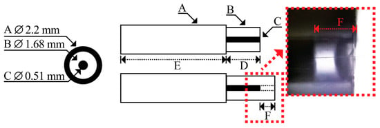
Figure 1.
Schematic representation of PTFE expansion following an ablation procedure and an actual zoomed microscope image of the region; (A) outer conductor, (B) dielectric-PTFE, (C) inner conductor, (D) quarter-wavelength, (E) immersion length, and (F) PTFE expansion after ablation.
The remainder of this paper is organised as follows. Section 2 begins with an introduction to PTFE as a polymer material and its essential characteristics. This is followed by a detailed description of the annealing process and the experimental methodologies employed to investigate thermal expansion of PTFE and its implications for ablation performance. Section 3 presents the results and discusses characterisation of the thermal expansion of PTFE, including a comprehensive comparison between annealed and non-annealed antennas, with specific emphasis on their ablation performance. Finally, Section 4 summarises the significant findings and their respective applications.
2. Materials and Methods
This section introduces PTFE and elaborates on its material properties, applications, and significance in microwave ablation. It then explains the annealing process applied to coaxial cables and the method employed for antenna fabrication. The experimental methodology encompasses the thermal characterisation of PTFE when subjected to ablation temperatures, in conjunction with the developed experimental setup. Next, it outlines the configuration of the microwave ablation system and the procedure for analysing the differences in ablation performance between annealed and non-annealed antennas. Finally, this section describes the post-processing technique utilised for quantifying and comparing the ellipticity of the ablation zones.
2.1. Polytetrafluoroethylene (PTFE)
PTFE, [-CF2-CF2-]n, is a thermoplastic polymer formed by polymerising tetrafluoroethylene monomer (CF2=CF2) at high temperatures and pressures. Depending on its molecular weight, PTFE melts at around 330 °C. When it cools from its melting phase, it starts to crystallise at around 325 °C and becomes solid, opaque, and waxy in appearance [26,27,28,29].
PTFE is utilised in many applications due to its chemical inertness and stability [27,28]. Due to its non-polar structure, low dielectric constant, low dielectric loss, and high resistivity, it is a well-suited material for cable insulation or microwave applications [30,31]. PTFE has high thermal stability and can maintain all its useful properties up to its melting point. With a very low coefficient of friction, PTFE is commonly used as a non-stick coating [27,28]. This polymer is known for its biocompatibility and finds extensive use in medical applications, including medical tubing and advanced catheters, among others [32,33].
In this study, the microwave monopole antenna was constructed from a Qaxial Semi-Rigid RG405 coaxial cable [34]. The selected coaxial cable, with a PTFE dielectric, was chosen for its biocompatibility, thermal stability, and consistent dielectric properties with temperature. Moreover, the reason behind the selection of RG405 is its ability to endure high temperatures (up to 165 °C) under powered conditions (≈92 W at 2.45 GHz), well below its melting point at 330 °C. However, following ablation procedures, experimental observations of untreated coaxial cables displayed noticeable, permanent PTFE deformation (expansion) [25]. The observed expansion did not correlate with the theoretical expansivity or the true thermodynamic coefficient of linear thermal expansion, α1, defined by Equation (1).
where L0 is the initial length in m, ΔL is the change in length or expansion in m, and ΔT is the change in temperature in °C [27,28]. R. Kirby [28] showed that PTFE samples, through different forming techniques (moulded and extruded), manifested congruent expansivity following annealing between −190 °C and 350 °C. In the case of RG405 coaxial cable, the impact of PTFE annealing becomes more intricate due to the outer conductor constricting the PTFE core. Consequently, this study extensively investigates the influence of coaxial annealing pre-fabrication on the antenna’s performance.
2.2. RG405 Coaxial Cable’s Annealing Process
An RG405 coaxial cable was cut along the longitudinal direction into 165 mm pieces. The coaxial cables were sparsely placed on an aluminium block in a thermal chamber (WT 120, Weiss Technik, Reiskirchen, Germany). The cables were annealed at 140 °C for approximately three hours, starting from room temperature. Following the heating cycle, the chamber, and consequently the test cables, were left to cool back naturally to room temperature. The complete thermal cycle is illustrated in Figure 2.
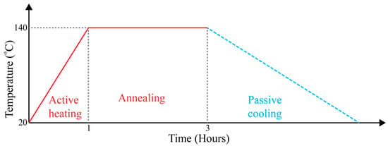
Figure 2.
The annealing process of the RG405 coaxial cable utilising a thermal chamber.
2.3. Insulated Monopole Antenna Fabrication
The two different experiments conducted in this study (PTFE thermal expansion characterisation and the ablation experiments) required fabrication of an insulated monopole antenna. In both cases, an antenna was used once and discarded following an experiment to avoid cumulative degradation errors.
The antennas used for the ablation experiments were constructed from an RG405 coaxial cable cut as indicated in Section 2.2. An SMA connector was soldered to one end for the annealed and non-annealed versions. The design and development of the uncooled insulated monopole are comprehensively described in [35], wherein two primary dimensions of significance during the antenna development process are detailed: the quarter-wavelength monopole length (D) and the antenna’s immersion length (E) (refer to Figure 1). Length (D) was achieved by exposing the PTFE solely by cutting the outer conductor. This was accomplished by cutting the outer conductor in an annular motion and limiting the cutting depth using a modified copper tube cutter (W127, WIGAM, Arezzo, Italy). This produced a repeatable and neat cut. The cut outer conductor was slid away to expose around 20 mm of the PTFE underneath. The length (D) was cut to 12.8 mm using a hand-driven 3D-printed rotary guillotine. This resulted in an immersion length (E) of 140 mm, excluding the SMA connector. Every antenna was assigned a unique identifier and underwent validation. The validation process utilised a Vector Network Analyser (VNA) ZNA50 (Rhode and Schwarz, Munich, Germany). The antennas were immersed in minced porcine liver, which was contained in a cylindrical plastic vessel sufficiently large to approximate a quasi-semi-infinite medium. This was achieved by adjusting the container size until no further changes were detected in the reflection coefficient. The return loss was measured at between 1.1 GHz and 3.8 GHz with 301 points, and the complete return loss profile was confirmed. A needle file was used for fine adjustments to improve the matching condition. It was ensured that the measured return loss was above 25 dB at 2.45 GHz; otherwise, the antenna was rejected.
Unlike the ablation experiments, the antennas intended for the PTFE thermal expansion characterisation experiments were neither energised nor matched with the surrounding medium (peanut oil). Thus, the antennas required no soldered SMA connector and equally no matching validation. In these cases, 70 mm pieces of RG405 coaxial cables were used. The length (D) was developed using the same copper tube cutter and hand-driven 3D-printed rotary guillotine as the antennas developed for the ablation experiments. However, the antennas meant for the PTFE thermal expansion characterisation experiments had a shorter length (E) of 50 mm to reduce cable waste, as the constricted PTFE below the outer conductor had no significant impact on the monopole’s matching condition during ablation. The antennas meant for the PTFE thermal expansion characterisation experiments had their dimensions/lengths measured and recorded using a toolmaker’s microscope (Maxtascan 2000, Graticules Optics Ltd, Tonbridge Kent, UK). All antennas were rigorously fabricated to ensure matching dimensions, resulting in a mean length (D) of 12.95 mm and a standard deviation of 0.1 mm. The process was equivalent for both annealed and non-treated antennas.
2.4. Developed Coaxial Cable PTFE Thermal Expansion Characterisation System
A system was developed to characterise PTFE expansion with a rise in temperature. A block diagram of the system is shown in Figure 3. The system consisted of a borosilicate beaker filled with peanut oil (Sol D’Olio, Olitalia, Forli, Italy). Peanut oil was utilised due to its elevated smoking point of 232 °C and clarity. Consequently, it is capable of enduring temperatures equivalent to those experienced during ablation, while simultaneously enabling real-time observation of the expansion of PTFE in the liquid via a camera. The beaker was totally insulated by being enclosed within two layers of thick cardboard all around. Three 125 W immersible heaters (10D60L230V125W1000TLS, Resistencias Industriales Maxiwatt, S.L., Alicante, Spain) were used to heat the peanut oil, and homogenous temperature throughout the beaker was ensured via continuous stirring with a hotplate/stirrer (Wise-Stir MSH-20A, witeg Labortechnik GmbH, Wertheim, Germany). Custom-built control hardware and a NI-USB-6211 DAQ card (National Instruments (NI), Austin, TX, USA) were used to actuate the three immersible heaters. A Type K thermocouple was placed inside the beaker in the vicinity of the antenna’s tip to measure the immediate surrounding temperature. The thermocouple was interfaced with the NI-9211 thermocouple DAQ. An analogue thermometer was used as a backup to monitor the temperature. Custom software was developed within NI LabVIEW 2023 Q3 to autonomously execute the experimental temperature profile and control the peanut oil’s temperature to set temperatures.
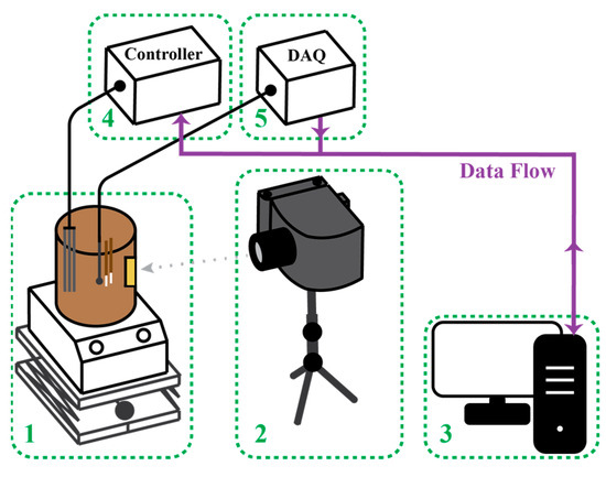
Figure 3.
The complete system used to investigate the expansion of PTFE: (1) hotplate/stirrer and insulated beaker filled with peanut oil on an adjustable lifting platform, (2) camera and macro lens on an adjustable tripod, (3) software control and data logging, (4) immersion heaters and control hardware, and (5) thermometry system.
A Canon (Uxbridge Middlesex, UK) EOS Rebel T6/1300D camera with a Tamron (Köln, Germany) SP 28–75 mm F/2.8 XR Di for Nikon F lens on an adjustable tripod was used to take pictures of the antenna’s tip during the heating and cooling cycles. The lens was focused directly on the antenna tips via a small window (cut in the insulating cardboard) located at the front of the beaker, facing the camera. Since the beaker was enclosed, proper lighting was ensured via a series of LEDs placed inside the beaker. Pictures were triggered via the camera software within the first 10 s after the set temperature was reached and stabilised.
2.5. Coaxial Cable PTFE Thermal Expansion Characterisation Experiment
During this experiment, the antennas were completely submerged in peanut oil in pairs and fixed such that the antenna tips were centred approximately in the middle of a small viewing window. In order to ensure consistent imaging conditions, antennas were positioned vertically in alignment with the inner wall of the beaker, thereby minimising distortions caused by glass refraction, oil opacity, and convective turbulence. The peanut oil was replenished around every three cycles to mitigate oxidation and prevent particulate contamination during the exchange of antennas.
The experiment was initiated at an oil temperature of 30 °C, which was raised in stages (70 °C, 80 °C, 100 °C, 120 °C, and 140 °C). The temperature was controlled at each stage until it was stabilised within +/−1 °C. Four pictures were taken at each temperature stage. The oil temperature was then cooled back to 30 °C, again taking four pictures at each temperature stage. Before and after the experiment, each antenna’s length was measured using a toolmaker’s microscope. In total, 16 annealed and 16 non-annealed antennas were investigated with this method.
The change in length was determined by measuring the change in pixels with open-source image processing software (US National Institutes of Health NIH-ImageJ) 1.54f [36]. The image was digitally focused on the antenna length (D) (refer to Figure 1), using the centre conductor as a guide to measure along the centre. The percentage change in pixels over the initial pixel value was then converted to a change in length in mm. This was achieved by exploiting the known initial length measured using a toolmaker’s microscope. A pixel-based mean PTFE length measurement was determined by calculating the mean from the four pictures at each temperature stage. The correlation of the percentage change in pixels to the percentage change in mm was validated through another experiment using a vernier calliper’s depth rod as a reference. The length of the depth rod varied between 12 mm and 14 mm, with a step size of 0.05 mm. The pixel-based measurement method was compared with the vernier calliper measurement, obtaining a mean error of just 0.92% over the whole population.
2.6. Microwave Ablation System
A system was developed to perform laboratory experiments on microwave ablation. The block diagram in Figure 4 shows the complete system, which can be divided into three main parts: the power delivery equipment (1–3), the developed uncooled coaxial-based monopole antenna immersed in biological tissue, (4) and the measurement and data acquisition system (5–8). The power delivery equipment comprises a signal generator (Anritsu, Luton Bedfordshire, UK, MG3694C), a 100 W power amplifier (BLMA130-100, BONN Elektronik, Holzkirchen, Germany), and a −50 dB dual directional coupler (BCD 0742-50/500, BONN Elektronik, Holzkirchen, Germany). The measuring devices were a four-channel thermometry system (Luxtron FOT Lab kit, Advanced Energy, Denver, CO, USA) paired with two fluoroptic temperature probes (Luxtron Fluoroptic STF probes, Advanced Energy, Denver, CO, USA) and a power meter (ML2438A, Anritsu, Luton Bedfordshire, UK) paired with two power sensors (MA2472A and MA2473D, Anritsu, Luton Bedfordshire, UK). Data logging was accomplished through custom-developed software running on NI LabVIEW. The microwave system was pre-characterised to account for insertion losses and amplifier gain and to ensure that the pre-established power was accurately delivered to the load.
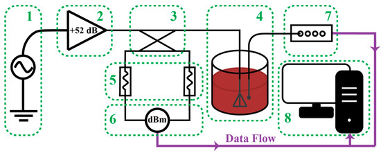
Figure 4.
Block diagram of the microwave ablation system: (1) signal generator, (2) 52 dB amplifier, (3) −50 dB dual directional coupler, (4) antenna in biological tissue, (5) power sensors, (6) power meter, (7) thermometry system, and (8) software control and data logging.
2.7. Microwave Ablation Experiments
Ex vivo porcine liver specimens were collected from the local abattoir less than an hour after animal slaughter. The specimens were transported in a plastic bag and kept inside a cooler bag to retain moisture. Then, the porcine liver was placed in a large plastic container and kept intact. A needle was used to pierce the liver’s external tough tissue to serve as a guide to insert the antenna. Depth makers were drawn on each antenna every 10 mm above length D (refer to Figure 1), and all antennas were immersed 40 mm into the tissue. Four to five antennas were pre-positioned per porcine liver, depending on the specimen size, before the ablation experiments commenced. Even though the antennas were energised one at a time, sufficient distance was maintained between them to prevent mutual interference. This study consisted of 32 ablation procedures (16 with annealed antennas and 16 with non-annealed antennas) at 50 W for a duration of 180 s. Tap water was used as a reference material to evaluate structural changes in the antenna induced by PTFE expansion. Return loss measurements were utilised as the primary metric for this evaluation. The complex permittivity of tap water was measured at 2.45 GHz (εTap: 76.14–j9.99) and was found to be in good agreement with both the experimentally measured permittivity of deionised water (εDI: 77.26–j9.215) and published literature values [37]. Although small differences in permittivity exist among water types, the study concentrated on relative variations in return loss rather than absolute values, thus making tap water a valid reference medium for assessing antenna performance under mechanical deformation. This experiment was conducted by first measuring return loss with the VNA in tap water, following antenna fabrication. The VNA was calibrated prior to each measurement campaign utilising an open, short, matched standard. Considering the brief duration of the experiment, instrument drift was deemed negligible. Return loss was measured across a frequency range of 1.1 GHz to 3.8 GHz, utilising 301 measurement frequency points, with the point of salient interest being 2.45 GHz. Then, following an ablation experiment, the antenna was removed from the liver sample, thoroughly cleaned with ethanol and deionised water to remove any residues, and then re-immersed in the formerly used tap water to re-measure the return loss.
2.8. Ablation Zone Extraction
Images of the dissected porcine liver were captured using a 4128 × 2322 resolution camera. These were taken following an ablation experiment. A stand was used to maintain approximately the same height and angle throughout all experiments. However, variations were inevitable, since the liver specimens were wobbly and irregularly shaped. As shown in Figure 5, images were taken with the antenna in place and a steel ruler in parallel along the ablation zone used as a reference. NIH-ImageJ 1.54f was used to extract the ellipticity of the ablation zone [36]. This was done with two different methods, as shown in Figure 5. Method one: an ellipse was best fitted using the bottom part of the ablation zone as a reference, ignoring the tailing section. Method two: the contour of the ablation zone was traced, including the tailing section. In both cases, the lesion created by the antenna was traced, following the contrast between the dark red colour of fresh liver and the pinkish colour where protein denaturation had occurred [38]. An inbuilt software option, ‘fit ellipse’, was used, which returned the major and the minor axes in pixel count with both methods. The ellipticity or flattening, f, was calculated using Equation (2) [39].
where a is the length of the major axis and b is the length of the minor axis. Since ellipticity is a ratio, pixel-to-metric conversion and calibration were not necessary. Ellipticity varies from 0 to 1, where 0 is a perfect sphere.
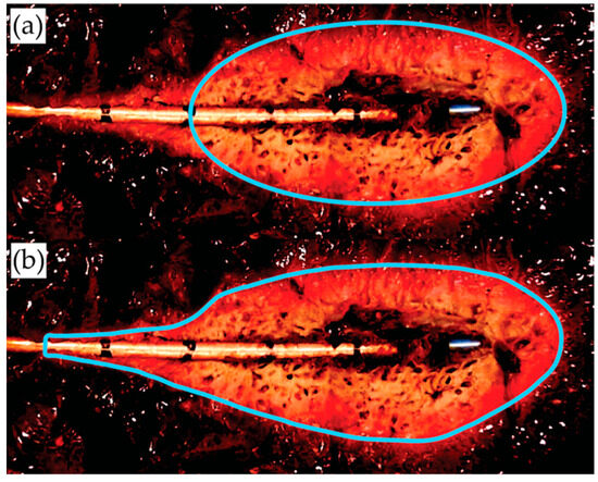
Figure 5.
A dissected liver with a typical ablation zone, antenna, and a traced lesion pattern post-processed using Image J 1.54f: (a) fitted ellipse and (b) traced region.
3. Results and Discussion
This section details the results and discussion of the following investigations: the thermal expansion behaviour of PTFE at ablation temperatures for both annealed and non-annealed antennas; the implications of annealing for antenna performance, as assessed through return loss measurements conducted before, during, and after ablation; and a comparative analysis of ablation lesion ellipticity between annealed and non-annealed cases.
3.1. PTFE Thermal Expansion
The mean (ΔL) and standard deviation (σΔL) of the change in PTFE length, measured using a toolmaker’s microscope, were calculated and are represented by the purple plots in Figure 6 at an ambient temperature of 30 °C. The non-annealed antennas exhibited PTFE expansion with an ΔL of 0.35 mm and a σΔL of 0.11 mm, while the annealed antennas exhibited PTFE shrinkage with an ΔL of −0.18 mm and a σΔL of 0.22 mm. In Figure 6, data measured during both heating and cooling cycles using the camera setup are displayed with red or blue plots. There was agreement between the camera-based measurements obtained at the end of the cooling cycles (at 30 °C) and those measured with a toolmaker’s microscope. This reinforces the validity of the camera setup. At the end of the cooling cycle, the non-annealed antennas exhibited an ΔL of 0.34 mm and a σΔL of 0.09 mm, while the annealed antennas exhibited an ΔL of −0.13 mm and σΔL of 0.12 mm. These results reaffirm previous findings, indicating PTFE expansion for non-annealed antennas and permanent shrinkage for annealed ones. The greater standard deviation seen in both sample groups from the toolmaker’s microscope measurements is attributed to unavoidable minor variations in antenna placement before and after the experimental measurements. Conversely, the developed camera system maintained consistent antenna positioning throughout the entire experimental process.
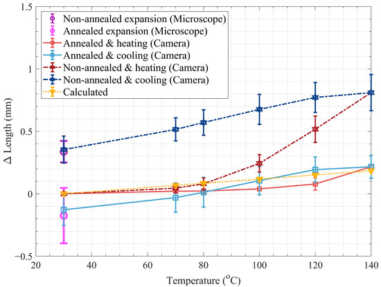
Figure 6.
PTFE thermal expansion in mm as a function of temperature.
The yellow line in Figure 6 represents theoretical unrestricted PTFE thermal expansion, ΔL, as calculated by Equation (1). The mean initial length (L0 = 12.95 mm) measured using a toolmaker’s microscope was inputted as the initial length L0 in Equation (1). The change in temperature, ΔT, was calculated from the initial temperature T0 of 30 °C and the temperature of the peanut oil’s target steady state temperature, Tss. Two values were considered for the linear coefficient of thermal expansion of PTFE, α1, 124 × 10−6 °C−1 and 135 × 10−6 °C−1, reflecting the variability range of this parameter found in the literature [28]. Disregarding the shrinkage observed in the experimental plots produced by the annealed antennas (light red/blue), there is notable agreement with the theoretical plot (yellow), as depicted in Figure 6.
Copper has a high thermal conductivity of 391 Wm−1 K−1 [40]. Consequently, there is a negligible thermal difference between the exposed PTFE section and the PTFE covered by the outer conductor. Additionally, copper has a low α1, 17.6 × 10⁻⁶ °C−1, especially relative to PTFE [41]. Therefore, during annealing, the covered PTFE could be considered restricted PTFE in terms of thermal expansion. Due to its very high viscosity, it is assumed that, during coaxial cable manufacturing, the PTFE was extruded using a high-pressure paste or ram extruder. This results in high residual compression stress in the PTFE tube, which causes non-linear expansion due to stress relaxation when it is heated. As can be seen in Figure 6, the highest elongation occurred around its glass transition temperature, Tg, at 126 °C, especially during the cooling cycle, that is, from a hotter to colder stage. Persistent PTFE residual polymer stresses following the extrusion process in coaxial cable manufacturing will contribute to the accentuated non-linear expansion achieved by non-annealed antennas. Figure 6 demonstrates how the annealing process releases manufacturing residual stresses so that the length of PTFE and the antenna efficacy will not change during ablation. Another observation is that the annealed antennas exhibit notably lower standard deviation than the non-annealed antennas during the heating cycles. The decrease in variability suggests improved dimensional stability owing to reduced non-linear expansion under ablation conditions. This is especially important, given that the applicator is disposed of after the ablation process. Greater standard deviation during the cooling cycle and minor shrinkage of PTFE were also noted in the annealed antennas, probably due to extended heating and subsequent uncontrolled natural cooling. This indicates that the parameters of the annealing process, especially the cooling rate, need further refinement. Future studies could benefit from incorporating a slower, more controlled cooling phase to increase the polymer’s entropy state, which may help alleviate residual stresses and minimise dimensional instability.
3.2. Comparison of Return Loss Before and After Ablation
Return loss was measured using a VNA before and after an ablation procedure, as described in Section 2.7. This was conducted to ascertain any correlation between changes in return loss due to expansion. Mean return loss and standard deviation at 2.45 GHz for both annealed (RWA and σRWA) and non-annealed (RWN and σRWN) antennas were calculated and plotted in Figure 7 to visually illustrate the changes. Before the experiment,
RWA and σRWA were 16.96 dB and 1.68 dB, respectively, whilst RWN and σRWN were 18.82 dB and 1.88 dB, respectively. After the experiment, RWA and σRWA changed to 11.25 dB and 2.82 dB, respectively, whilst RWN and σRWN changed to 6.66 dB and 0.23 dB, respectively. The antennas were all developed under similar conditions; thus, the initial return loss was understandably similar. However, there was a significant difference after ablation. Although the annealed antennas experienced a change in return loss of 5.67 dB, the non-annealed antennas had a change of 12.16 dB. This signifies that the expansion occurring during ablation significantly degrades antenna return loss. In addition, the annealing process reduces this effect.
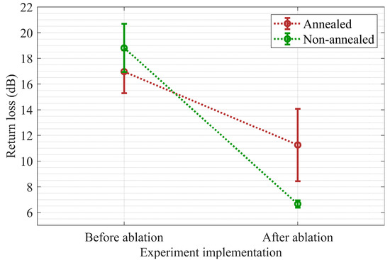
Figure 7.
Measured return loss with a VNA at 2.45 GHz while the antenna was immersed in tap water before/after an ablation procedure.
3.3. Investigation of Return Loss During Ablation
The power measurement system, consisting of a power meter and two power sensors, measured real-time power every second during ablation, which was then converted to return loss using Equation (3).
where Pfwd is forward power, Pref is reflected power, and R is return loss. The sum of the coupling factor error, the power sensor accuracy error, and the directional coupler insertion loss were compensated for by subtracting 1.98 dB from the return loss. This value was achieved from other characterisation experiments at 2.45 GHz. Although the power meter is a broadband device, the frequency was restricted to 2.45 GHz via the signal generator, and therefore the measured power was only that at the frequency of interest. This was validated on a spectrum analyser, where the measured quality factor of both the signal generator and the amplifier output when energised was 1.06 × 10⁹. The mean return loss (Rs) and standard deviation (σRs) were calculated for each time sample (1 s). The results obtained are shown in Figure 8 and summarised in Table 1. At the start of the experiment, the antenna return loss was relatively the same for both scenarios. However, within the first 60 s of ablation, the annealed antennas outperformed the non-annealed antennas, notably around 21 s when the maximum Rs difference of 2.54 dB was observed. Despite this, the annealed antennas experienced higher σRs, which, at worst, was almost similar to that of the non-annealed antennas. Between 60 s and 120 s, changes in the tissue properties caused an increased mismatch for both antenna sets. However, the annealed antennas maintained a better match until the final 60 s, when both antenna sets showed similar behaviour.
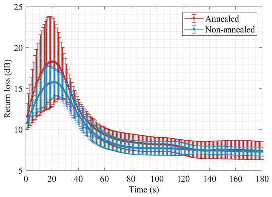
Figure 8.
Measured return losses at 2.45 GHz, acquired from the power meter during ablation of porcine liver at 50 W.

Table 1.
Return loss mean and standard deviation of key points in Figure 8.
3.4. Lesions’ Ellipticity Analyses
The lesion ellipticity (determined as described in Section 2.8) results were initially plotted on a quantile–quantile (q–q) plot to confirm whether they followed a normal distribution. The four data sets were considered normally distributed, as only minor deviation at the extremes was observed. These were then fitted to a normalised probability density function that follows a Gaussian distribution. The resultant plots are shown in Figure 9. Dark/light red plots show the ellipticity of ablation achieved with annealed antennas, whilst the dark/light blue plot resulted from non-annealed antennas. Solid and dotted lines distinguish the different measurement methods. Subtle ellipticity improvement is observed with both methods for the annealed antennas. With the fitted ellipse method, the mean decreased from 0.62 to 0.54, whereas with the tailing method, it decreased from 0.68 to 0.64. This shows that the annealed antennas produced more spherical lesions, as desired.
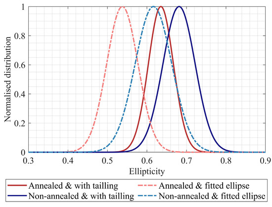
Figure 9.
A comparison of ablation lesion ellipticity fitted to a normal distribution between annealed and non-annealed antennas.
3.5. Discussion of the Practical Advantages of Annealing for Uncooled Monopole Antennas
Most clinically available microwave ablation applicators utilise active liquid or gas cooling via a jacket surrounding the antenna [4,5,6,7,8,9,10]. While cooling facilitates higher energy delivery with minimised coaxial cable diameters and reduces reverse heating effects, it also introduces a significant limitation for dual-mode applications [2,42]. Specifically, the presence of an interface medium between the antenna and the tissue can interfere with sensing capabilities.
In contrast, this study focuses on an uncooled monopole antenna, which must withstand all generated heat during treatment. Unlike cooled designs, the uncooled antenna eliminates intermediate media, simplifying direct tissue interaction. However, this approach introduces potential risks, including PTFE dielectric expansion, as discussed in Section 3.1, and subsequent performance degradation due to elevated heating, as discussed in Section 3.2 and Section 3.3. To address these challenges, this study has thoroughly investigated the feasibility of an uncooled monopole antenna and has concentrated on its structural stability when subjected to ablative temperatures. It was shown that annealing of the coaxial cable potentially suppresses PTFE expansion.
While previous studies have examined alternative antenna topologies like dipoles and slotted-type antennas for dual-mode applications [19,20], this research uses a monopole design, which was used in a preliminary dual-mode ablation investigation described in [21] and will be utilised in future studies. The monopole’s replicable and simple design facilitated better isolation of the PTFE expansion effects compared to more complex designs not used in this study. Furthermore, by quantifying changes in the antenna structure, this investigation enables future numerical modelling analysis and dual-mode experiments to distinguish more effectively between scattering parameter variations caused by permittivity changes in surrounding tissue and those arising from antenna structural changes.
Alternative designs utilising ceramic or zirconium tips have been proposed, providing improved thermal insulation and stability due to the intrinsic material properties [43,44]. However, these solutions significantly increase the cost and complexity of the antenna. This study demonstrates that controlled annealing of standard RG405 coaxial cables can potentially be an alternative solution.
4. Conclusions
This study investigated the impact of PTFE expansion in an uncooled insulated monopole antenna on return loss and the resulting ablation zone. Two types of expansion were observed during ablative temperature PTFE expansion characterisation: predominant permanent expansion attributed to residual stresses caused during manufacturing and expansion attributed to linear expansion of PTFE. This study further demonstrated that annealing suppresses the first type of expansion. Ablation experiments have shown that PTFE expansion reduces return loss of the antenna. This reduction in return loss causes the ablation lesion to become more elongated, increasing ellipticity. Finally, this study demonstrated that pre-annealing RG405 coaxial cable prior to antenna fabrication improves the performance of an uncooled coaxial insulated monopole antenna. This finding is significant, as it facilitates the practical use of an uncooled antenna, capitalising on its advantages in dual-mode applications.
Author Contributions
Conceptualisation, E.J.D., L.F., C.S. and F.C.; methodology F.C. and E.J.D.; software, F.C. and E.J.D.; validation, F.C., E.J.D., L.F., A.R., J.B. and I.F.; formal analysis, F.C.; investigation, F.C.; resources, J.B. and I.F.; data curation, J.B. and I.F.; writing—original draft preparation, F.C.; writing—review and editing, F.C., E.J.D., L.F., C.S. and A.R.; visualisation, F.C.; supervision, E.J.D., L.F. and C.S.; project administration, E.J.D., L.F. and C.S.; funding acquisition, E.J.D., L.F. and C.S. All authors have read and agreed to the published version of the manuscript.
Funding
This research received no external funding.
Institutional Review Board Statement
The animal study protocol was approved by the Institutional Review Board (or Ethics Committee) of the University of Malta (protocol code SCI-2022-00140 and date of approval 19 April 2023).
Informed Consent Statement
Not applicable.
Data Availability Statement
The data presented in this study are available on request from the corresponding author. The data are not publicly available due to privacy.
Acknowledgments
This work was supported in part by the project ‘Setting up of transdisciplinary research and knowledge exchange (TRAKE) complex at the University of Malta (ERDF.01.124)’, which is being co-financed through the European Union through the European Regional Development Fund 2014–2020. This work was developed as part of the Project Ablaze, funded by Xjenza Malta and Technology and the Scientific Technological Research Council of Türkiye (TÜBİTAK) through the Xjenza Malta-TÜBİTAK 2023 Joint Call for R&I projects. This initiative is part of the PRIMA programme supported by the European Union. The authors thank the Department of Microelectronics and Nanoelectronics for providing their electric temperature test chamber and for assistance. The authors thank Andrew Finch and Josef Borg for providing their camera and lens and for their assistance.
Conflicts of Interest
The authors declare no conflicts of interest. The funders had no role in the design of the study; in the collection, analyses, or interpretation of data; in the writing of the manuscript; or in the decision to publish the results.
Nomenclature
The following abbreviations are used in this manuscript:
| Acronyms | Descriptions |
| PTFE | Polytetrafluoroethylene |
| α1 | Coefficient of linear thermal expansion in °C−1 |
| L0 | Initial length in m |
| ΔL | Expansion in m |
| ΔT | Change in temperature in °C |
| VNA | Vector network analyser |
| NI | National Instruments |
| εTap | Complex permittivity of tap water |
| εDI | Complex permittivity of deionised water |
| f | Ellipticity |
| a | Length of the major axis in pixels |
| b | Length of the minor axis in pixels |
| ΔL | Mean of the change in PTFE length in mm |
| σΔL | Standard deviation of the change in PTFE length in mm |
| L0 | Mean initial length measured using a toolmaker’s microscope in mm |
| Tss | Steady state temperature in °C |
| Tg | Glass transition temperature in °C |
| RWA | Mean return loss at 2.45 GHz for annealed antennas in dB |
| σRWA | Return loss standard deviation at 2.45 GHz for annealed antennas in dB |
| RWN | Mean return loss at 2.45 GHz for non-annealed antennas in dB |
| σRWN | Return loss standard deviation at 2.45 GHz for non-annealed antennas in dB |
| Pfwd | Forward power in dBm |
| Pref | Reflected power in dBm |
| R | Return loss in dB |
| Rs | Mean return loss for each one-second time sample in dB |
| σRs | Return loss standard deviation for each one-second time sample in dB |
References
- Tammam, E.; Said, A.M.; Ibrahim, A.A.; Galal, A.I.A. About the Interstitial Microwave Cancer Ablation: Principles, Advantages and Challenges. IEEE Access 2020, 8, 49685–49694. [Google Scholar] [CrossRef]
- Lubner, M.G.; Brace, C.L.; Hinshaw, J.L.; Lee, F.T. Microwave Tumor Ablation: Mechanism of Action, Clinical Results, and Devices. J. Vasc. Interv. Radiol. 2010, 21, S192–S203. [Google Scholar] [CrossRef]
- Simon, C.J.; Dupuy, D.E.; Mayo-Smith, W.W. Microwave Ablation: Principles and Applications. Radiographics 2005, 25, 69–84. [Google Scholar] [CrossRef] [PubMed]
- Solero Microwave Tissue Ablation System—AngioDynamics. Available online: https://www.angiodynamics.com/product/solero-microwave-tissue-ablation-system/ (accessed on 2 April 2025).
- HS Hospital Service. Available online: https://www.hshospitalservice.com/categoria_prodotti/microonde-radiofrequenza/ (accessed on 2 April 2025).
- Medwaves. Available online: https://medwaves.com/ (accessed on 2 April 2025).
- ECO Medical Technology. Available online: https://www.ecomedicaltech.com/ (accessed on 2 April 2025).
- EmprintTM. Medtronic. Available online: https://www.medtronic.com/covidien/en-gb/products/ablation-systems.html# (accessed on 2 April 2025).
- Vison Medical USA. Available online: https://visonmedicalusa.com/products/ (accessed on 2 April 2025).
- Varian—Microthermx. Available online: https://www.varian.com/products/interventional-solutions/microwave-solutions/intelliblate (accessed on 9 June 2025).
- Brace, C.L. Temperature-Dependent Dielectric Properties of Liver Tissue Measured during Thermal Ablation: Toward an Improved Numerical Model. In Proceedings of the 2008 30th Annual International Conference of the IEEE Engineering in Medicine and Biology Society, Vancouver, BC, Canada, 20–25 August 2008; IEEE: New York, NY, USA; pp. 230–233. [Google Scholar] [CrossRef]
- Rossmanna, C.; Haemmerich, D. Review of Temperature Dependence of Thermal Properties, Dielectric Properties, and Perfusion of Biological Tissues at Hyperthermic and Ablation Temperatures. Crit. Rev. Biomed. Eng. 2014, 42, 467–492. [Google Scholar] [CrossRef]
- Fu, F.; Xin, S.X.; Chen, W. Temperature- and Frequency-Dependent Dielectric Properties of Biological Tissues within the Temperature and Frequency Ranges Typically Used for Magnetic Resonance Imaging-Guided Focused Ultrasound Surgery. Int. J. Hyperth. 2014, 30, 56–65. [Google Scholar] [CrossRef] [PubMed]
- Bindu, G.; Abraham, S.; Aanandan, C.K.; Mathew, K.T. Microwave Characterization of Female Human Breast Tissues. In Proceedings of the 2006 European Conference on Wireless Technologies, Manchester, UK, 10–12 September 2006; IEEE: New York, NY, USA, 2006; pp. 123–126. [Google Scholar]
- Brace, C.L.; Etoz, S. An Analysis of Open-Ended Coaxial Probe Sensitivity to Heterogeneous Media. Sensors 2020, 20, 5372. [Google Scholar] [CrossRef]
- Fallahi, H.; Sebek, J.; Prakash, P. Broadband Dielectric Properties of Ex Vivo Bovine Liver Tissue Characterized at Ablative Temperatures. IEEE Trans. Biomed. Eng. 2021, 68, 90–98. [Google Scholar] [CrossRef]
- Bonello, J.; Athanasiadis, A.-P.I.; Farrugia, L.; Sammut, C.V. A Study on the Variation of Dielectric Properties of Grey Matter with Temperature. In Proceedings of the 2018 EMF-Med 1st World Conference on Biomedical Applications of Electromagnetic Fields (EMF-Med), Split, Croatia, 10–13 September 2018; IEEE: New York, NY, USA, 2018; pp. 1–2. [Google Scholar]
- Lopresto, V.; Pinto, R.; Cavagnaro, M. Experimental Characterisation of the Thermal Lesion Induced by Microwave Ablation. Int. J. Hyperth. 2014, 30, 110–118. [Google Scholar] [CrossRef]
- Wang, P.; Brace, C.L. Tissue Dielectric Measurement Using an Interstitial Dipole Antenna. IEEE Trans. Biomed. Eng. 2012, 59, 115–121. [Google Scholar] [CrossRef]
- née Reimann, C.H.; Bazrafshan, B.; Schüßler, M.; Schmidt, S.; Schuster, C.; Hübner, F.; Vogl, T.J.; Jakoby, R. A Dual-Mode Coaxial Slot Applicator for Microwave Ablation Treatment. IEEE Trans. Microw. Theory Tech. 2019, 67, 1255–1264. [Google Scholar] [CrossRef]
- Cilia, F.; Farrugia, L.; Bonello, J.; Sammut, C.V.; Farhat, I.; Dimech, E.J. Analysis of Return Loss with an Uncooled Coaxial Monopole Antenna During Microwave Ablation. In Proceedings of the 2024 18th European Conference on Antennas and Propagation (EuCAP), Glasgow, UK, 17–22 March 2024; IEEE: New York, NY, USA, 2024; pp. 1–5. [Google Scholar]
- Anderson, J.M.; Sibbald, C.L.; Stuchly, S.S. Dielectric Measurements Using a Rational Function Model. IEEE Trans. Microw. Theory Tech. 1994, 42, 199–204. [Google Scholar] [CrossRef]
- Kraszewski, A.; Stuchly, M.A.; Stuchly, S.S. ANA Calibration Method for Measurements of Dielectric Properties. IEEE Trans. Instrum. Meas. 1983, 32, 385–387. [Google Scholar] [CrossRef]
- Stuchly, M.A.; Stuchly, S.S. Coaxial Line Reflection Methods for Measuring Dielectric Properties of Biological Substances at Radio and Microwave Frequencies-A Review. IEEE Trans. Instrum. Meas. 1980, 29, 176–183. [Google Scholar] [CrossRef]
- Cilia, F.; Farrugia, L.; Bonello, J.; Sammut, C.V.; Farhat, I.; Dimech, E.J. Performance Degradation of an Uncooled Coaxial Monopole Antenna: A Preliminary Investigation of PTFE Expansion at Ablative Temperatures. In Proceedings of the 2023 17th European Conference on Antennas and Propagation (EuCAP), Florence, Italy, 26–31 March 2023; IEEE: New York, NY, USA, 2023; pp. 1–5. [Google Scholar]
- Araki, Y. Thermal Expansion Coefficient of Polytetrafluoroethylene in the Vicinity of Its Glass Transition at about 400 °K. J. Appl. Polym. Sci. 1965, 9, 421–427. [Google Scholar] [CrossRef]
- Blumm, J.; Lindemann, A.; Meyer, M.; Strasser, C. Characterization of PTFE Using Advanced Thermal Analysis Techniques. Int. J. Thermophys. 2010, 31, 1919–1927. [Google Scholar] [CrossRef]
- Richard, K. Kirby Thermal Expansion of Polytetrafluoroethylene (Teflon) From –190 °C to +300 °C. J. Res. Natl. Bur. Stand. 1956, 57, 91–94. [Google Scholar]
- Schlipf, M.; Schuster, M. Designing with PTFE; BIBLIOTHEK DER TECHNIK/VERLAG MODERNE INDUSTRIE: Landsberg, Germany, 2013. [Google Scholar]
- Bur, A.J. Dielectric Properties of Polymers at Microwave Frequencies: A Review. Polymer 1985, 26, 963–977. [Google Scholar] [CrossRef]
- Johnson, G.R. Dielectric Properties of Polytetrafluoroethylene. In Proceedings of the Conference on Electrical Insulation & Dielectric Phenomena—Annual Report, Pocono Manor, PA, USA, 3–6 October 1966; IEEE: New York, NY, USA; pp. 78–83. [Google Scholar]
- Ratner, B.D.; Hoffman, A.S.; Schoen, F.J.; Lemons, J.E. Biomaterials Science: An Introduction to Materials in Medicine; Academic Press: Cambridge, MA, USA, 2012. [Google Scholar]
- Migonney, V. Biomaterials; John Wiley & Sons, Inc.: Hoboken, NJ, USA, 2014. [Google Scholar]
- QAXIAL—Quality Coaxial. Semirigid PTFE Microwave Coaxial Cable RG405-CU. Available online: https://www.rf-microwave.com/en/qaxial/rg405-cu/semi-rigid-coaxial-cable/rg405-cu/ (accessed on 2 April 2025).
- Cilia, F.; Farrugia, L.; Bonello, J.; Farhat, I.; Sammut, C.V.; Joe Dimech, E. Design of an Uncooled Microwave Monopole Antenna for Tissue Ablation at 2.45 GHz. In Proceedings of the 2021 15th European Conference on Antennas and Propagation (EuCAP), Düsseldorf, Germany, 22–26 March 2021; IEEE: New York, NY, USA; pp. 1–5. [Google Scholar]
- Schindelin, J.; Arganda-Carreras, I.; Frise, E.; Kaynig, V.; Longair, M.; Pietzsch, T.; Preibisch, S.; Rueden, C.; Saalfeld, S.; Schmid, B.; et al. Fiji: An Open-Source Platform for Biological-Image Analysis. Nat. Methods 2012, 9, 676–682. [Google Scholar] [CrossRef]
- Ellison, W.J.; Lamkaouchi, K.; Moreau, J.-M. Water: A Dielectric Reference. J. Mol. Liq. 1996, 68, 171–279. [Google Scholar] [CrossRef]
- Deshazer, G.; Hagmann, M.; Merck, D.; Sebek, J.; Moore, K.B.; Prakash, P. Computational Modelling of 915 MHz Microwave Ablation: Comparative Assessment of Temperature-Dependent Tissue Dielectric Models. Med. Phys. 2017, 44, 4859–4868. [Google Scholar] [CrossRef]
- Weisstein, E.W. Flattening. Available online: https://mathworld.wolfram.com/Flattening.html (accessed on 2 April 2025).
- Li, M.; Zinkle, S.J. Physical and Mechanical Properties of Copper and Copper Alloys. In Comprehensive Nuclear Materials; Elsevier: Amsterdam, The Netherlands, 2012; pp. 667–690. [Google Scholar]
- Wang, K.; Reeber, R. Thermal Expansion of Copper. High Temp. Mater. Sci. 1996, 2, 181–186. [Google Scholar]
- Huang, H.; Zhang, L.; Moser, M.A.J.; Zhang, W.; Zhang, B. A Review of Antenna Designs for Percutaneous Microwave Ablation. Phys. Medica 2021, 84, 254–264. [Google Scholar] [CrossRef] [PubMed]
- Huang, X.; Zhou, Y.; Liu, Z.; Qiu, B. Design of a Closed Dual-slot Antenna for Spherical Hepatic Microwave Ablation. Int. J. RF Microw. Comput. Eng. 2022, 32, e23009. [Google Scholar] [CrossRef]
- Kuwano, S.; Nemoto, K.; Michiyama, T. A New Interstitial Antenna for Microwave Ablation. IEICE Commun. Express 2017, 6, 200–203. [Google Scholar] [CrossRef][Green Version]
Disclaimer/Publisher’s Note: The statements, opinions and data contained in all publications are solely those of the individual author(s) and contributor(s) and not of MDPI and/or the editor(s). MDPI and/or the editor(s) disclaim responsibility for any injury to people or property resulting from any ideas, methods, instructions or products referred to in the content. |
© 2025 by the authors. Licensee MDPI, Basel, Switzerland. This article is an open access article distributed under the terms and conditions of the Creative Commons Attribution (CC BY) license (https://creativecommons.org/licenses/by/4.0/).