1. Introduction
With the gradual increase in coal mining depth in China, traditional mining methods and technologies are increasingly unable to meet the challenges posed by more severe mining environments and complex geological conditions. This is particularly evident in the process of multi-seam mining, where the complex interactions between coal seams and the physical properties of the overlying strata give rise to a range of significant issues [
1,
2]. Multi-seam mining often leads to a series of safety hazards, such as secondary roof fracturing, interlayer separation-induced water hazards, and strong mine pressure [
3]. These problems not only reduce mining efficiency but can also result in serious safety issues and accidents. As the cumulative mining thickness increases during multi-seam extraction, the water-conducting fracture zone in the roof progressively develops upward. Once it reaches an aquifer, it may channel water into the mine, potentially causing water inrushes or even mine flooding [
4]. Therefore, studying the movement patterns of roof layers during multi-seam mining is of great theoretical significance for the prevention of water-related hazards and the assurance of safe coal production in the mines.
The development height of the water-conducting fracture zone is one of the key factors leading to roof-related water hazards in coal mines; it is directly related to the safe operation of the mine and the protection of water resources. This zone refers to the fractured area in the overlying strata that, after coal seam extraction, forms through-going fractures under mining-induced stress, allowing connectivity with overlying aquifers or surface water. If the development height becomes excessive, it can connect the aquifer layers, potentially causing water inrush and mine flooding accidents. Therefore, scholars both at home and abroad have conducted long-term and in-depth theoretical investigations, field measurements, and modeling studies focusing on its development mechanisms, evolution patterns, and height prediction. These efforts have yielded abundant results and led to the development of various prediction methods. Wu Jianhong et al. [
5] drew upon a systematic analysis of field observation data from numerous engineering cases to thoroughly summarize the dynamic development patterns of the caving zone and the water-conducting fracture zone in the overlying strata during coal seam mining. They found that the heights of the two zones are significantly correlated with mining height, lithological assemblage, and stratigraphic structure. On this basis, they developed empirical prediction formulas. Zhou Ze [
6] emphasized the significant controlling role of the internal structure of overlying strata on the initiation, propagation, and final morphology of the water-conducting fracture zone. He pointed out that factors such as the layering thickness of hard rock, the alternation of soft and hard rock layers, the presence of key strata, and their fracturing characteristics profoundly influence the development path, connectivity, and overall height of the fracture zone. His work advanced the study of the water-conducting fracture zone from a macro-level statistical perspective to a more refined analysis based on the mechanical structure of rock layers. Xu Yanchun [
7] conducted research with a clear focus on engineering applications. By integrating detailed, measured data from multiple fully mechanized mining faces, he specifically analyzed the differential impacts of roof lithology—particularly the contrast between hard and soft rocks—on the development of the “two zones” (caving zone and water-conducting fracture zone). He distinguished between empirical formulas for hard-roof and soft-roof conditions, thereby enhancing the accuracy and relevance of fracture zone height prediction under varying geological conditions. Dekang Zhao [
8] introduced a stochastic regression method to construct a prediction model that effectively addresses the inherent uncertainty and variability of geotechnical parameters. By applying probabilistic and statistical techniques, the method quantifies the confidence intervals of the prediction results, offering a new approach to estimating the height of the water-conducting fracture zone that incorporates geological uncertainty. Qiang Wu [
9], employing the radial basis function neural network model within the MATLAB (2016) platform, developed an intelligent prediction method that was specifically designed for estimating the height of roof fracture zones under fully mechanized caving mining conditions. By learning the complex nonlinear mapping relationships among mining conditions, lithological parameters, and fracture zone heights for a large number of known samples, the model demonstrates strong adaptive prediction capabilities. Yuehan Wang [
10] innovatively coupled the discrete element method (DEM) with the boundary element method (BEM). This coupled approach was successfully applied to simulate the entire process of mining-induced subsidence, including the stress redistribution in the overlying strata, the evolution of displacement trajectories, and the resulting height and spatial morphology of the water-conducting fracture zone. It provides a powerful numerical experimental tool for understanding the dynamic development of the fracture zone from a mechanical perspective.
In the repeated mining of multiple coal seams, subsequent mining operations cause further damage to the already disturbed rock mass, thereby expanding the range of rock layer damage. In recent years, numerous researchers have conducted systematic studies on the activity characteristics of the roof under closely spaced coal seam mining conditions, using methods such as mechanical modeling, similar material experiments, and numerical simulations. Zhang Jie, He Yifeng, and others [
11,
12,
13] analyzed the repeated mining conditions of shallow coal seam groups; they revealed the development height and distribution characteristics of fractures in each coal seam and validated their findings using the elastic foundation beam theory. Liu Shiqi, Xu Yanchun, and others [
14] started with the complexity of the interaction between coal seams to propose a new method to improve the accuracy of “two-zone” predictions. They emphasized the need to comprehensively consider coal seam spacing and mining height in the prediction process and developed a three-step calculation method comprising “coal seam group classification identification”, “converted mining height calculation”, and “two-zone height estimation”. Ghabraie [
15] proposed a novel surface subsidence prediction method based on numerical simulation, which combines finite element analysis (FEA) with discrete element methods (DEM) to comprehensively consider factors such as the rock mass’s mechanical properties, coal seam spacing, and mining sequence, effectively improving the accuracy of subsidence prediction in multi-coal-seam mining. Li Shuqing, He Xueqiu, and others [
16] studied the double-unloading phenomenon induced by closely spaced coal seam mining. Under double unloading, the top and bottom plates of the coal seams are repeatedly disturbed, causing some fractures to undergo a multi-stage evolution process of generation, expansion, compaction, and re-opening, leading to fracture forms that are distinct from those seen in single coal seam mining. Using the Bulta Mine as a case study, Zhen Zhixin [
17] systematically analyzed the relationship between the key layer structure and fracture zone development under repeated mining conditions. Through theoretical derivation, simulation calculations, and field monitoring, the mechanism of progressive instability and complex failure of the key layer during mining was revealed, further explaining its intrinsic connection with mining pressure, fracture development, and surface subsidence. On this basis, a fitting model was also established for the relationship between the height of the water-conducting fracture zone and mining seam thickness. Hu Yongzhong [
18] conducted similar material simulation experiments to study the evolution mechanism of coal seam group overburden fractures under different mining methods, finding that the total thickness of composite coal seams, interlayer distance, and mining sequence are the main factors influencing fracture development.
A significant amount of research has now been conducted, both domestically and internationally, on the destruction patterns of overburden under the conditions of the repeated mining of coal seam groups. However, research that specifically focuses on the destruction patterns of overburden in gently inclined coal seam groups during downward mining operations is relatively scarce. This study takes the Yindonggou Coal Mine as the research object and, through theoretical analysis, numerical simulations, and field measurements, analyzes the evolution of overburden destruction during the downward mining of gently inclined coal seam groups. This study aims to provide theoretical foundations and technical references for coal seam mining research under similar conditions.
2. Overview of the Mining Area
2.1. Mining Conditions
The Yindonggou Coal Mine is located in the northern part of the Wangwa Mining Area, Pengyang County, Ningxia Hui Autonomous Region. The mine has a north-south length of approximately 5.19 km, an east-west width of about 3.75 km, and a total area of 12.461 km
2. The designed production capacity is 3.0 Mt/a, with a service life of 56.0 years. The mine uses a slanted shaft with single-level development, employing a fully mechanized one-pass full-height coal mining process. Currently, the main mining face is located in the 11th mining district, and the excavation layout of the mining works is shown in
Figure 1. The mine is currently recovering coal from the 110404 mining face.
The 110404 mining face is located in the southern wing of the 11th mining district of the Yindonggou Coal Mine and is the first mining face of the 4th coal seam. The coal seam is 2.7 m thick and is classified as a medium-thick coal seam. The mineable strike length is 773 m, with an inclined length of 266 m and an average dip angle of 15°, making it a gently inclined coal seam. The burial depth is approximately 465 m. On both the east and west sides, the coal seam is surrounded by entities from the 4th coal seam. The roof rock layer primarily consists of fine sandstone, with small amounts of mudstone and carbonaceous mudstone, ranging in thickness from 1.2 to 11.7 m, with an average thickness of 4.3 m. The pseudo-roof consists mainly of carbonaceous mudstone, with a thickness of 0.5 m. The floor rock layer is mainly fine sandstone, with small amounts of fine-grained sandstone in some areas, ranging in thickness from 1.44 to 7.53 m, with an average thickness of 4.38 m. The pseudo-floor is not developed.
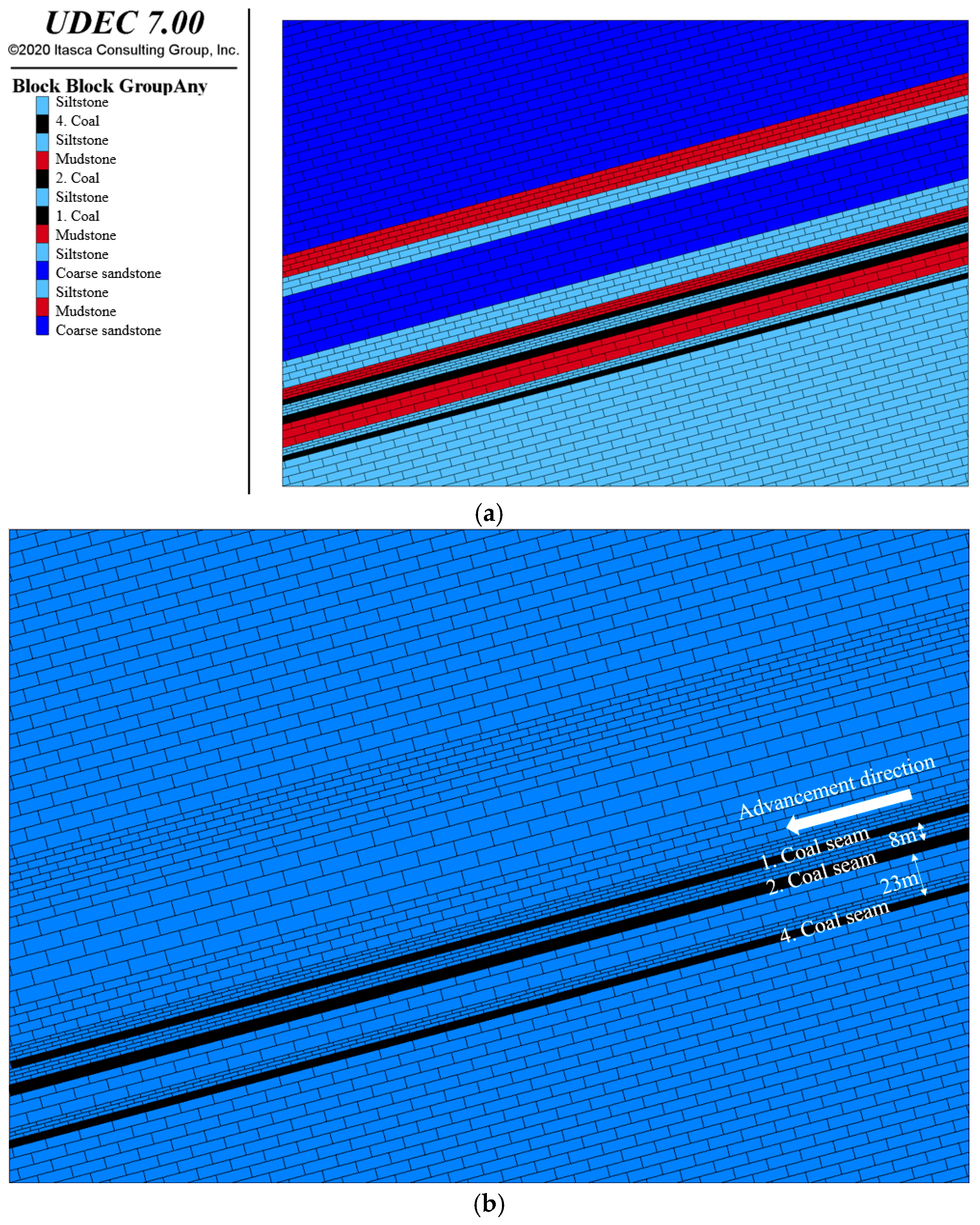
The main tunnels of the northern adjacent mine are protected by coal pillars, while the southern side is adjacent to the Yindongzi old kiln (with a 55 m protective coal pillar). Above, there are the 110204 and 110104 goaf areas. The coal seam thickness of the 110104 working face is 2.9 m, with an interlayer distance of about 8 m from the 110204 working face. The coal seam thickness of the 110204 working face is 3.8 m, with an interlayer distance of about 23 m from the 110404 working face. As shown in
Figure 2.
2.2. Natural Geography
The mining area is located in the loess hill and gully region, which is characterized by complex terrain and lush vegetation. The highest elevation is +1903 m, and the lowest is +1530 m, with an average elevation ranging from +1530 m to +1850 m. The average elevation of the erosion base level at the bottom of the gully is +1600 m. The general trend in the northwest is high and the southeast is low. Within the coalfield, vertical joints in the loess are well-developed, often forming steep cliffs on both sides of the gullies. The gullies are subject to water erosion, with depths ranging from 100 to 300 m, creating various types of loess landforms such as loess ridges, plateaus, hills, valleys, spines, and pillars.
The largest loess ridge in the region is the Wangwaho Liang, located in the central part of the coalfield. It is over 10 km long and serves as a watershed with a north–south orientation. It divides the rainfall into two parts: the western rainfall flows westward into the Guanting River, then southward into the Rujian River, and eventually reaches Gansu. The river to the east flows from here toward the Anchengchuan River in Gansu. The area does not have significant perennial surface runoff. Apart from occasional short channels formed after heavy rain, there is generally no runoff. Only a few small streams form due to the emergence of spring clusters.
2.3. Hydrogeology
The aquifer within the well field consists of the Quaternary aquifer, which receives the most precipitation recharge. The lithology here is primarily loess, with good vertical permeability, and water is mainly stored at the bottom of the Quaternary formation. The unit water inflow is 0.003 L/(s·m) and the permeability coefficient is 0.014 m/d, indicating very weak aquifer water content. There is no significant impermeable layer between the Paleogene aquifer section and the Quaternary aquifer section. The Paleogene aquifer, which is located above the red clay, is considered part of the same aquifer as the Quaternary one, with weak water-bearing properties. The lower part of the Anding Formation contains relatively thick coarse sandstone, which is loosely cemented and has developed fractures and voids. The simple hydrological observation data indicate that the unit water inflow of this aquifer is 0.81 L/(s·m), and the permeability coefficient is 0.412 m/d, suggesting a moderate water-bearing capacity. According to the BK1 drilling data, the coarse-grained sandstone in the Zhi Luo Formation accounts for nearly 50% of the aquifer, with a strong water-bearing capacity. However, according to lithological analysis, there are impermeable layers of claystone interbedded within the coarse-grained sandstone, which hinders hydraulic connectivity between the aquifers, thus leading to noticeable heterogeneity in the water-bearing capacity of the Zhi Luo Formation. The Yan’an Formation aquifer section is divided into three segments, based on sedimentary cycles: the water-bearing section above Coal Seam 5, the water-bearing section between Coal Seams 5 and 12, and the water-bearing section below Coal Seam 12. Coal Seam 4 is currently being mined and is affected by the water-bearing section above Coal Seam 5, which is influenced by coal seams and impermeable lithologies such as mudstone and siltstone. The hydraulic connectivity of the aquifer is weak, vertically, and the water-bearing capacity is also weak.
The impermeable layer within the wellfield consists of impermeable Paleogene sandy claystone layers. The lithology mainly includes purple-red sandy clay, silt, and gravel, with an average thickness of around 40 m, and is relatively stable. This stratum exhibits good impermeability and stability, serving as a stable barrier between the unconsolidated rock layers and the bedrock aquifer within the wellfield. The impermeable siltstone and mudstone layers in the central part of the Zhiluo Formation are composed of light gray and gray-green siltstone and mudstone, with a relatively large and stable thickness averaging around 30 m. This is also a stable impermeable layer. The impermeable layers in various sections of the Yan’an Formation consist of intercalated siltstone, mudstone, and coal layers, including the coal seams themselves, as well as the interbedded sandy mudstone layers at the top and bottom. The lithology primarily consists of coal, dark gray mudstone, and siltstone interlayers, with a dense structure. The distribution within the wellfield is relatively stable, and the impermeability is relatively good. The geological column diagram is shown in
Figure 3.
3. Theoretical Analysis of the Roof Failure Law in the Downward Mining of Gently Inclined Coal Seam Groups
The research on the development height laws of the collapse zone and fracture zone in a single coal seam is currently mature and is theoretically guided by the three-lower coal mining code. However, there is no clear prediction method to determine the development height of the fall zone and fracture zone during the mining of close-range coal seams. Pan Ruikai, Cao Shugang, et al. employed the modified development height calculation formula to calculate the development height of the fracture zone in the close-range coal seam group and obtained a comprehensive mining thickness calculation model for close-range coal seam mining [
19].
3.1. Comprehensive Mining Thickness for Close-Range Coal Seam Mining
Based on research into the comprehensive mining thickness calculation model for close-range coal seam mining developed by Pan Ruikai and Cao Shugang, an inclination correction function was introduced to construct a comprehensive mining thickness calculation model that was suitable for the downward mining of gently inclined, closely spaced coal seams, as shown in
Figure 4. Its core advantage lies in quantifying the superposition effect and sequential dependence of multi-layer mining, providing a theoretical basis for roof management and safety warnings.
In the figure, MU represents the mining thickness of the upper coal seam, in meters; ML represents the mining thickness of the lower coal seam, in meters; m represents the subsidence value of the interlayer rock strata after the lower coal seam mining, in meters. Meq represents the comprehensive mining thickness, in meters; h represents the thickness of the interlayer between the upper and lower coal seams, in meters.
Figure 4 shows that for gently inclined, closely spaced coal seams, after the lower coal seam is mined, the interlayer rock strata between the coal seams will fracture and subside. The subsidence of the top of the interlayer rock strata will result in further damage to the caving zone and fracture zone of the upper coal seam’s goaf area. Therefore, the comprehensive mining thickness is the sum of the mining thickness of the upper coal seam and the secondary subsidence value of the top position of the interlayer rock strata caused by the mining of the lower coal seam. Thus, we have:
In the formula:
qi represents the subsidence coefficient at the top position of the spacer layer after the mining of the lower coal seam.
In the formula: Ks represents the rock layer collapse and fragmentation coefficient of the lower coal seam; α represents the coal seam dip angle.
The comprehensive mining thickness of the double coal seam after mining can be obtained as follows:
3.2. Calculation of the Development Height of the “Two Zones” for Close-Range Coal Seam Group Mining
Based on the comprehensive mining thickness for the downward mining of gently inclined coal seam groups, and according to the calculation formulas for the caving zone and water-conducting fracture zone height in the 2017 version of the “Three-Lower Coal Mining Code” and the “Three-Lower Coal Mining Guide”, the heights of the “two zones” for gently inclined coal seam groups are predicted (refer to
Table 1 and
Table 2) [
20].
Based on the geological data from Yindonggou Coal Mine, and according to the uniaxial compressive strength of rocks under natural conditions, the overlying strata can be classified into different types, as detailed in
Table 3 and
Table 4.
The physical and mechanical property tests of the roof rocks in the coal seams indicate that the roofs of Coal Seam 1, Coal Seam 2, and Coal Seam 4 mainly consist of sandstone with a small amount of mudstone, and the uniaxial compressive strength of the rock layers ranges from 20 to 40 MPa. According to the classification standards for overlying strata lithology, the overlying rock layers of Coal Seam 1, Coal Seam 2, and Coal Seam 4 in the Yindonggou Coal Mine are classified as medium-hard. The medium-hard lithology formula is used to calculate the caving zone and water-conducting fracture zone height after the repeated mining of working face 110404.
According to the spatial relationship table for coal seams in Yindonggou Coal Mine, as shown in
Table 5, the development heights of the “two zones” after the mining of Coal Seam 1, Coal Seam 2, and Coal Seam 4 are calculated. This study focuses on the evolution law of overlying strata damage during the downward mining of gently inclined coal seam groups.
After mining of the 110104 working face of Coal Seam 1:
Height of the collapse zone:
Height of the water-conducting fissure zone:
After mining of the 110104 working face of Coal Seam 1 was completed, the height development range of the collapse zone was 6.69–11.09 m, and the height development range of the water-conducting fracture zone was 29.59–40.79 m.
After mining of the 110204 working face of Coal Seam 2:
The rockfall and fragmentation coefficient
Ks of Coal Seam 2 is taken as 1.04, the coal seam dip angle α is 15°, the distance
h between Coal Seam 1 and Coal Seam 2 is 8 m, and the mining thickness
ML of Coal Seam 2 is 3.8 m. Therefore, after mining of the 110204 working face of Coal Seam 2, the subsidence coefficient of the interlayer rock layer is:
The subsidence value of the interlayer rock strata is:
The comprehensive mining thickness of double-layer coal is:
Height of the collapse zone:
Height of the water-conducting fissure zone:
After mining the 110204 working face in Coal Seam 2, the top of the interlayer rock subsided by 3.5 m, resulting in a comprehensive mining thickness of 6.4 m for the coal seam group. The development height range of the caving zone is 24.05 to 33.47 m above the top of Coal Seam 1, and the development height range of the water-conducting fracture zone is 74.10 to 94.94 m above the top of Coal Seam 1.
After mining the 110404 working face of Coal 4, the rockfall and fragmentation coefficient
Ks of Coal Seam 4 is taken as 1.04, the coal seam dip angle α is 15°, the distance
h between Coal Seam 2 and Coal Seam 4 is 23 m, and the mining thickness
ML of Coal Seam 4 is 2.7 m. Therefore, after the mining of Coal Seam 4, the subsidence coefficient of the rock layer between Coal Seam 2 and Coal Seam 4 is:
The subsidence value of the rock layer between Coal Seam 2 and Coal Seam 4 is:
At this time, the subsidence coefficient of the rock layer between Coal Seam 1 and Coal Seam 2 has changed. The changed subsidence coefficient is:
The subsidence value of the rock layer between Coal Seam 1 and Coal Seam 2 changes to:
In Equations (13) and (14), ML is the sum of the mining thickness of Coal Seam 2 (3.8 m) and the subsidence value of the top position of the rock layer between Coal Seams 2 and 4, caused by the mining of Coal Seam 4 (1.8 m).
The comprehensive mining thickness of the three-layer coal is:
Height of the collapse zone:
Height of the water-conducting fissure zone:
After mining of the 110404 working face of Coal Seam 4 was completed, the top rock strata of the spacer layer between Coal Seam 1 and Coal Seam 2 sank by 5.3 m. At this time, the comprehensive mining thickness of the coal seam group after mining was 8.2 m. The height development range of the sag zone is 30.73–40.15 m above the top of Coal Seam 1, and the height development range of the water-conducting fracture zone is 92.26–113.10 m above the top of Coal Seam 1.
4. Numerical Simulation Study on the Roof Failure Law of Downward Mining in Gently Inclined Coal Seam Groups
In this section, the UDEC (7.00) numerical simulation software was used successively to study the development height of fractures in the overlying strata during the mining process for Coal Seam 1, Coal Seam 2, and Coal Seam 4, to analyze the failure and evolution law of the overlying strata during the downward mining of the gently inclined coal seam group [
21], and to verify the research results of the theoretical analysis.
4.1. Establishment of the Numerical Simulation Model
Based on the numerical simulation study, combined with the geological data of Yindonggou Coal Mine and the physical and mechanical parameters of the rock mass shown in
Table 6, a numerical simulation model with dimensions of 400 m × 340 m was established. The simulated mining heights for Coal Seam 1, Coal Seam 2, and Coal Seam 4 were 2.9 m, 3.8 m, and 2.7 m, respectively, with all coal seams having a dip angle of 15°. The numerical simulation model is shown in
Figure 5.
The contact parameters between the modules used in this model are as follows:
Block contact property materia Coarse sandstone stiffness-shear 5.40 × 10¹⁰ stiffness-normal 7.80 × 10¹⁰ friction 34 cohesion 2.89 × 10⁶.
Block contact property materia Siltstone stiffness-shear 3.79 × 10¹⁰ stiffness-normal 4.04 × 10¹⁰ friction 32 cohesion 2.32 × 10⁶.
Block contact property materia Mudstone stiffness-shear 3.46 × 10¹⁰ stiffness-normal 3.23 × 10¹⁰ friction 28 cohesion 1.41 × 10⁶.
Block contact property materia Coal seam stiffness-shear 2.00 × 10¹⁰ stiffness-normal 1.32 × 10¹⁰ friction 21 cohesion 1.25 × 10⁶.
To account for the influence of boundary effects on the calculations, 40-meter-wide boundary coal pillars were reserved on both the left and right sides of the model, to eliminate boundary interference. Each coal seam is planned to be mined for 320 m, with an excavation step of 20 m. After the overlying strata stabilize following the mining of the upper coal seam, the lower coal seam is mined until fully extracted. Since the model only extends up to the top of the Zhiluo Formation, the overlying strata and loose layers that are not included in the model are applied as a load on the upper boundary. The burial depth of the upper boundary is 291 m, with an equivalent load of 7.28 MPa being applied. The bottom boundary and both the left and right sides are treated as zero-displacement constrained boundaries.
4.2. Numerical Simulation Analysis of the Evolution Law of Overlying Rock Fractures
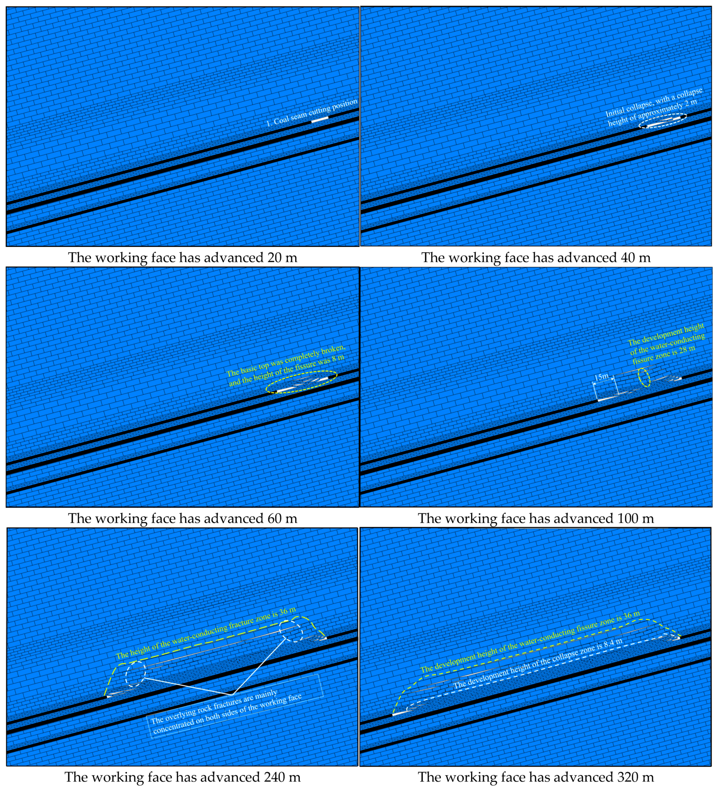
As shown in
Figure 6, when the working face of Coal Seam 1 advances 20 m, no collapse occurs in the overlying roof strata. When the working face advances to 40 m, the immediate roof space undergoes its initial break and collapse, with a collapse height of approximately 2 m. The thick, hard rock strata above the roof do not show significant fracturing, and only slight disturbances appear in front of the coal wall. When the working face advances to 60 m, the main roof experiences its initial break, with a fracture height of 8 m. The entire main roof collapses, and the fallen strata cover the entire goaf area. Separation fractures are formed, with a relatively small separation height. After the working face stabilizes, the fracture development height reaches 8 m, and the fractures continue to propagate upward. When the working face advances to 100 m, the overlying strata in the middle of the goaf break at a location 15 m behind the working face. At this point, a hinged structure forms in the thick, hard rock strata, which still serve a load-bearing function. The collapse height reaches 6 m, and the fracture zone extends up to 28 m. After this, the height of the water-conducting fracture zone increases slowly. When the working face advances to 240 m, as the goaf area expands, the collapse zone height reaches approximately 8 m, and the water-conducting fracture zone height increases to 36 m. The fractures in the overlying strata are mainly concentrated on both sides of the working face. Beyond this point, the water-conducting fracture zone does not develop further, and the strata in the goaf gradually become compacted. When the working face advances to 320 m, with the continued retreat of the working face, the collapse zone height remains at 8.4 m, and the height of the water-conducting fracture zone remains at 36 m. Therefore, after the extraction of Coal Seam 1, the final development height of the collapse zone is 8.4 m, and the development height of the water-conducting fracture zone is 36 m.
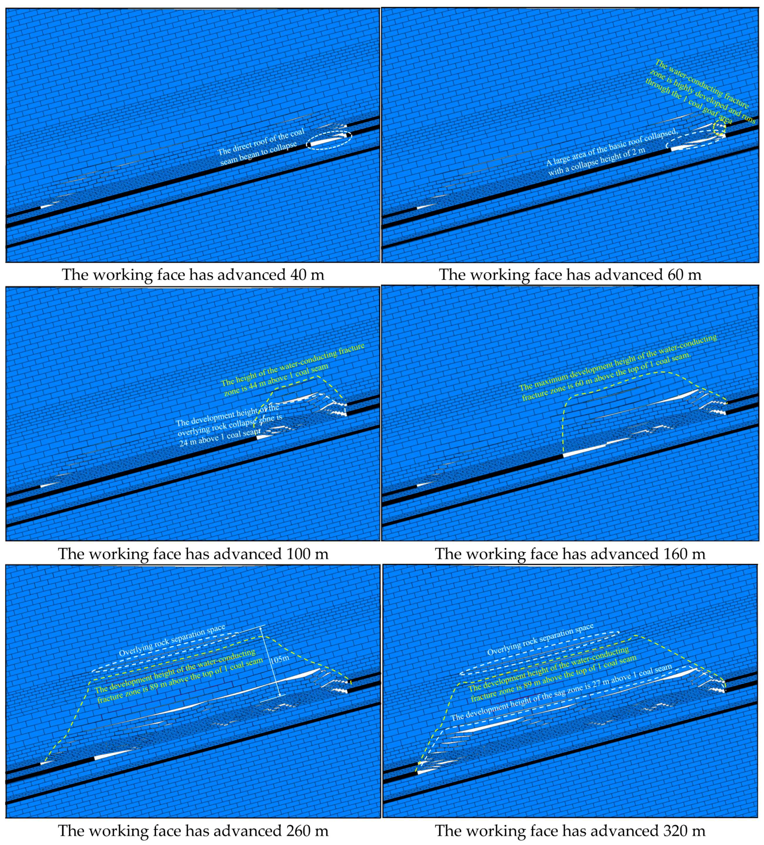
Based on the mining of Coal Seam 1, Coal Seam 2 is subsequently extracted. As shown in
Figure 7, when the working face advances to 40 m, fracturing first occurs in the lower part of the immediate roof strata. When the overhanging length of the initial roof reaches 20 m, the strata fracture once again, followed by the roof’s collapse. When the working face is 60 m from the cut-out entry, the main roof fractures, resulting in a large-scale collapse. The strata do not rotate, and the disturbance to the goaf and overlying strata of the upper coal seam is minimal. At this point, the collapse height is 2 m, and the height of the water-conducting fracture zone extends through the goaf of Coal Seam 1. As the working face continues to advance, reaching 100 m, the collapse zone penetrates the interburden and connects with the goaf of the upper coal seam. The degree of disturbance to the upper coal seam increases, and the height of the water-conducting fracture zone above the mined-out Coal Seam 1 begins to develop further upward, extending to 44 m above the top of Coal Seam 1. The collapse zone height develops to 24 m above Coal Seam 1, after which its growth slows. When the working face advances to 160 m, the water-conducting fractures continue to expand, with increasing fracture aperture. Reactivation of the overlying strata occurs behind the working face. At this stage, the maximum height of fracture development reaches 60 m above the top of Coal Seam 1. When the working face advances to 260 m, differences in lithology and physical-mechanical properties among the overlying strata result in varying deformation and subsidence rates between adjacent layers, leading to interlayer separation. The separation space develops at 105 m above the top of Coal Seam 1. At this point, the height of the water-conducting fracture zone reaches 89 m above the top of Coal Seam 1 but does not extend through to the upper separation layer. Beyond this stage, the height of the water-conducting fracture zone no longer increases, reaching its maximum extent. When the working face advances to 320 m, mining has reached the stopping line. The separation layer at 105 m above the top of Coal Seam 1 has developed further, but the development is relatively slow. The height of the water-conducting fracture zone remains at 89 m above the top of Coal Seam 1, and the collapse zone has developed to a height of 27 m. Therefore, after extraction of Coal Seam 2, the water-conducting fracture zone and collapse zone co-develop with those of Coal Seam 1. The final development height of the water-conducting fracture zone is 89 m above the top of Coal Seam 1, and the collapse zone reaches a height of 27 m above Coal Seam 1.
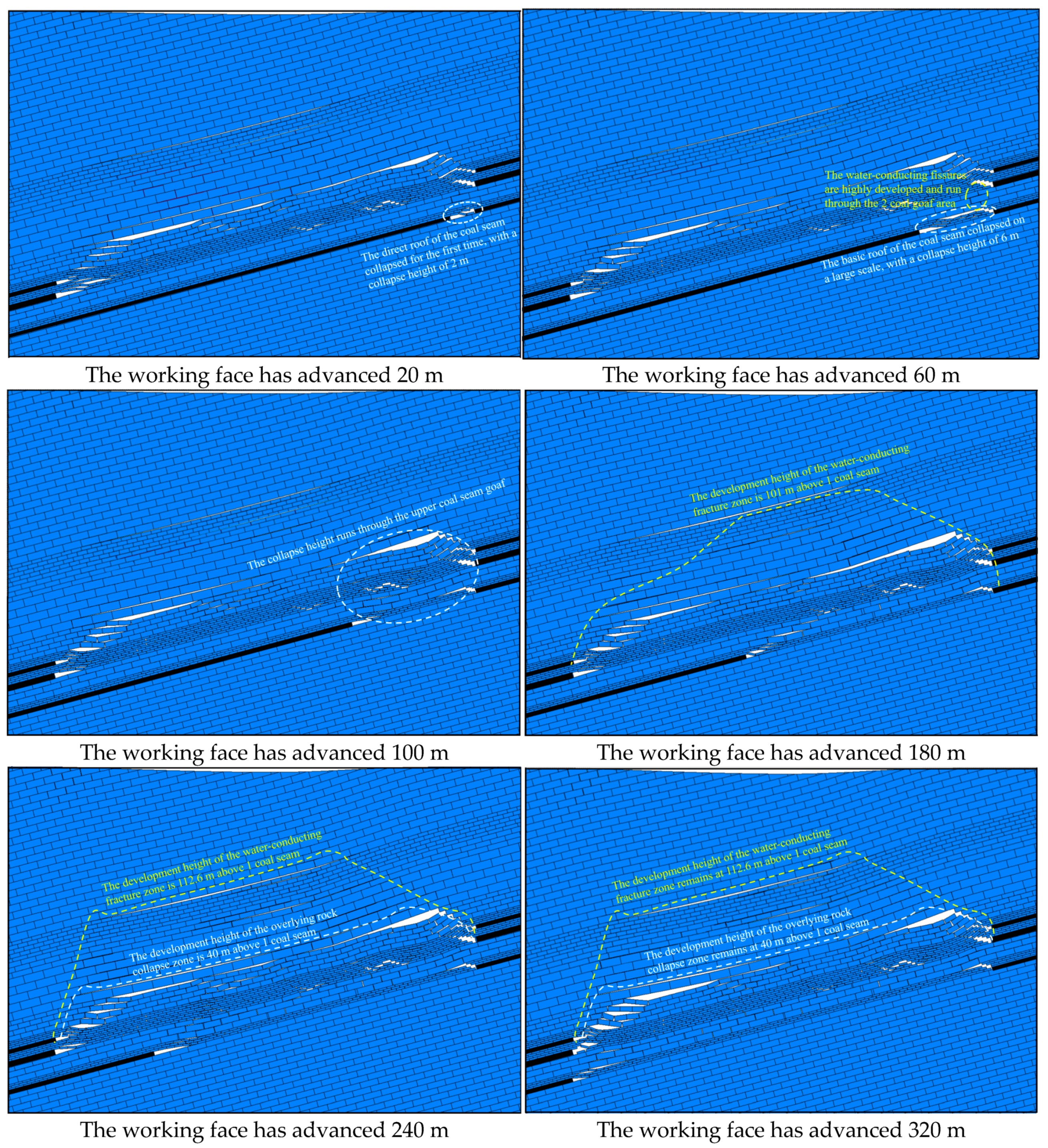
After the goaf and overlying strata of Coal Seams 1 and 2 have stabilized, Coal Seam 4 is mined. As shown in
Figure 8, when the working face advances to 20 m, the immediate roof experiences its initial collapse, with a collapse height of approximately 2 m and an overhang length of about 6 m. When the working face advances to 60 m, the main roof fractures and undergoes large-scale collapse, causing minimal disturbance to the goafs and overlying strata of the upper seams. At this point, the collapse height is 6 m, and the water-conducting fracture zone extends through the goaf of Coal Seam 2. When the working face reaches 100 m, the strata fracture again, and the collapse height extends through the Coal Seam 2 goaf, reaching 34 m above the top of Coal Seam 1. At 180 m, as the mining length of the lower coal seam increases, the influence on the overlying strata expands, and the water-conducting fractures develop upward to 101 m above the top of Coal Seam 1. This is located below the separation layer but does not penetrate it. The fractures in the overlying strata within the fracture zone are mainly horizontal, and the fractures in the upper part of the goaf gradually close. When the working face advances to 240 m, the collapse zone develops to a height of 40 m above the top of Coal Seam 1, and the water-conducting fracture zone reaches 112.6 m above the top of Coal Seam 1, penetrating the separation layer. After this point, the disturbance of the lower seam mining on the overlying strata decreases, and the collapse zone and water-conducting fracture zone no longer develop. The fractures exhibit an “M”-shaped distribution. At 320 m, mining has reached the stopping line. The height of the collapse zone remains at 40 m above the top of Coal Seam 1, and the height of the water-conducting fracture zone remains at 112.6 m. Therefore, after the extraction of Coal Seam 4, the water-conducting fracture zone co-develops with those of Coal Seams 1 and 2, reaching a final height of 112.6 m above the top of Coal Seam 1, and the collapse zone reaches a height of 40 m above Coal Seam 1.
In summary, during the downward mining process of the gently inclined coal seam group, multiple reactivations of the overlying strata occur. Under the conditions of “goaf–working face” and “goaf–goaf–working face”, the fractures in the overlying strata undergo six dynamic cyclic stages: generation, expansion, closure, regeneration, penetration, and reclosure. After the extraction of Coal Seam 1, the height of the water-conducting fracture zone is 36 m, and the height of the collapse zone is 8.4 m. After the extraction of Coal Seam 2, the water-conducting fracture zone and collapse zone combine with the roof damage caused by the extraction of Coal Seam 1, forming a joint damage zone. The height of the water-conducting fracture zone is 89 m above the top of Coal Seam 1, and the collapse zone is 27 m above the top of Coal Seam 1. After the extraction of Coal Seam 4, the water-conducting fracture zone and collapse zone, along with the roof damage caused by the extraction of Coal Seams 1 and 2, form a joint damage zone again. The height of the water-conducting fracture zone is 112.6 m above the top of Coal Seam 1, and the height of the collapse zone is 36.5 m above the top of Coal Seam 1.


 ,
, 


