Article

Effect of Heating Rate on the Properties and Mechanism of Nanocomposite Ceramic Coatings Prepared by Slurry Method

1
National Special Superfine Powder Engineering Research Center of China, School of Chemistry and Chemical Engineering, Nanjing University of Science and Technology, Nanjing 210094, China
2
School of Mechanical Engineering, Nanjing University of Science and Technology, Nanjing 210094, China
3
CITIC Heavy Industries (Beijing) New Energy Material Technology Company, Beijing 102628, China
*
Author to whom correspondence should be addressed.
These authors contributed equally to this work.
Appl. Sci. 2025, 15(12), 6561; https://doi.org/10.3390/app15126561
Submission received: 6 May 2025 / Revised: 2 June 2025 / Accepted: 9 June 2025 / Published: 11 June 2025

Abstract

:
Nano-titanium dioxide ceramic coatings exhibit excellent wear resistance, corrosion resistance, and self-cleaning properties, showing great potential as multifunctional protective materials. This study proposes a synergistic reinforcement strategy by encapsulating micron-sized Al2O3 particles with nano-TiO2. A core-shell structured nanocomposite coating composed of 65 wt% nano-TiO2 encapsulating 30 wt% micron-Al2O3 was precisely designed and fabricated via a slurry dip-coating method on Q235 steel substrates. The microstructure and surface morphology of the coatings were characterized using scanning electron microscopy (SEM) and X-ray diffraction (XRD). Comprehensive performance evaluations including densification, adhesion strength, wear resistance, and thermal shock resistance were conducted. Optimal coating properties were achieved under the conditions of a binder-to-solvent ratio of 1:15 (g/mL), a heating rate of 2 °C/min, and a sintering temperature of 400 °C. XRD analysis confirmed the formation of multiple crystalline phases during the 400 °C curing process, including titanium pyrophosphate (TiP2O7), aluminum phosphate (AlPO4), copper aluminate (Cu(AlO2)2), and a unique titanium phosphate phase (Ti3(PO4)4) exclusive to the 2 °C/min heating rate. Adhesion strength tests revealed that the coating sintered at 2 °C/min exhibited superior interfacial bonding strength and outstanding performance in wear resistance, hardness, and thermal shock resistance. The incorporation of nano-TiO2 into the 30 wt% Al2O3 matrix significantly enhanced the mechanical properties of the composite coating. Mechanistic studies indicated that the bonding between the nanocomposite coating and the metal substrate is primarily achieved through mechanical interlocking, forming a robust physical interface. These findings provide theoretical guidance for optimizing the fabrication process of metal-based ceramic coatings and expanding their engineering applications in various industries.

1. Introduction

Metal-based ceramic coating is a general term for a ceramic protective layer or surface film applied to the surface of a metal substrate [1,2]. The preparation of ceramic coatings on metal substrates can combine the excellent properties of metals and ceramics to achieve complementary and optimized performance [3]. Metal-based ceramic coatings have a high melting point, high hardness, excellent chemical and thermal stability, as well as excellent resistance to high-temperature oxidation and corrosion, which can simultaneously meet the requirements of structural properties [4,5,6,7,8]. In the field of machinery manufacturing, for high-speed operation, frequent friction of mechanical parts, such as bearings, gears, etc., ceramic coating can significantly reduce the surface friction coefficient, improve the efficiency of mechanical transmission, reduce maintenance costs, and resist the erosion of various chemical media, so that the mechanical parts in the harsh working conditions still maintain good working performance [9,10]. Ceramic coating has excellent anti-corrosion performance and smooth surface properties, which can solve the problems of seawater corrosion and marine organisms’ adhesion on the hull surface [11,12]. Because of its excellent resistance to high-temperature oxidation and corrosion, it is often used as a rocket nozzle, engine combustion chamber, combustion chamber of internal combustion engines, gas turbines and other parts of the high-temperature gas corrosion and thermal barrier [13,14].
The key to the stability of the bonding properties of metal-based ceramic coatings lies in the characteristic state of the metal-ceramic interface. The metal-ceramic interface refers to the metal matrix and ceramic reinforced phase, the chemical composition of the significant changes and constitutes a combination of each other’s tiny transition region, which can play the role of load transfer [15]. The absence of chemical bonding of atoms on the surface of the solid phase, which is more energetic than inside the crystal, leads to unavoidable interatomic energy conversion, electron transfer, and formation of new chemical bonds when the metal is docked to the ceramic surface. These changes in microscopic behavior make the metal-ceramic interface present a special location, composition intertwined, complex chemical properties and other characteristics, directly affecting the macroscopic properties of the interface structure [16,17].
Common techniques for the preparation of metal-based ceramic coatings include thermal spraying [18], sol-gel method [19], deposition method [20], laser cladding method [21], thermochemical reaction method [22], and slurry method [23]. Among them, the slurry method is a process in which a ceramic coating with specific properties is formed by mixing a binder with an aggregate in an appropriate ratio and applying it to the surface of a pretreated metal substrate after curing.
The slurry method has the advantages of simple process, convenient operation, low preparation cost, as well as being free from site and environmental restrictions, controllable coating thickness, and can be used for the preparation of multi-component ceramic coatings [24,25], so it has a wide range of prospects for the application of metal-based ceramic coatings.
The slurry method is commonly used to prepare oxide ceramic coatings, and common systems include silicon oxide (SiO2) [26], aluminum oxide (Al2O3) [27], zirconium oxide (ZrO2) [28], magnesium oxide (MgO) [29], and titanium oxide (TiO2) [30], etc. Among them, titanium dioxide ceramic coatings exhibit good heat resistance, high oxidation resistance, and excellent corrosion resistance due to its excellent chemical stability and environmental friendliness, making it an important corrosion and wear resistant coating material [31,32,33,34]. Lakkimsetty coated nanocomposites on 304 stainless steel substrates based on dip-coating method in thin-film technology and successfully prepared nano-TiO2 composite coatings with good corrosion resistance through corrosion resistance and stability tests [35]. Haewon successfully prepared low coating damage and high corrosion resistance nano-TiO2 coatings on MS mild steel by using the doctor blade coating method, which enhanced the structural and morphological properties and corrosion resistance of mild steel (MS) plates [36].
In the TiO2 and Al2O3 composite coating system, TiO2, which has a lower melting point, is able to improve the toughness of the composite coating and enhance the bonding force between Al2O3 grains [37,38]. By optimizing the ratio of TiO2 to Al2O3 powder, TiO2-Al2O3 composite oxide powders with different properties can be prepared [39]. Zhang investigated the microstructure and wear properties of Al2O3-13 wt% TiO2 coatings prepared by plasma spraying agglomerated nanoparticle powders, and found that the microhardness of the nanostructured coatings was about 15%~30% higher than that of the conventional coatings, with a significant increase in wear resistance [40]. Ahn used plasma spraying technique to prepare Al2O3-TiO2 nanocoatings, and four nanostructured Al2O3-13 wt% TiO2 coatings were prepared by varying the plasma spraying parameters, and the wear test results showed that the nanostructured coatings were three to four times more wear-resistant than the conventional coatings [41].
Current research shows that the proportion of TiO2 is usually less than 30 wt%, and the content of more than 50 wt% is rarely studied, and Al2O3 as the backbone of the wear-resistant phase can significantly improve the hardness of the coating through the grain refinement and dispersion reinforcement and the formation of a continuous corundum network to give the system a high load-bearing capacity [42]. However, the high content of Al2O3 is prone to cause interfacial stress concentration leading to the increase of wear rate, and there is a risk of grain boundary embrittlement of pure Al2O3 in high-temperature oxidizing environment at 400~500 °C. Existing researches are mostly focused on the Al2O3-phosphoric acid system (through the formation of AlPO4 network to realize the low-temperature densification), and the mechanism of synergism of multicomponents has not been explored sufficiently.
In this study, a synergistic strengthening scheme of nano-TiO2-coated Al2O3 is proposed to design a core-shell structure of 65 wt% nano-TiO2-coated 30 wt% micrometer Al2O3, which maintains a high level of corrosion resistance while forming a submicrometer reinforcement network through interfacial metallurgical bonding. This system has a broad application potential in the field of aerospace high-temperature parts protection, marine equipment corrosion-resistant coatings and heavy machinery wear-resistant linings, especially suitable for high-temperature working conditions under the environment of high load-bearing components of the surface reinforcement, for the performance of multi-component ceramic coatings synergistic design to provide a new paradigm.

2. Materials and Methods

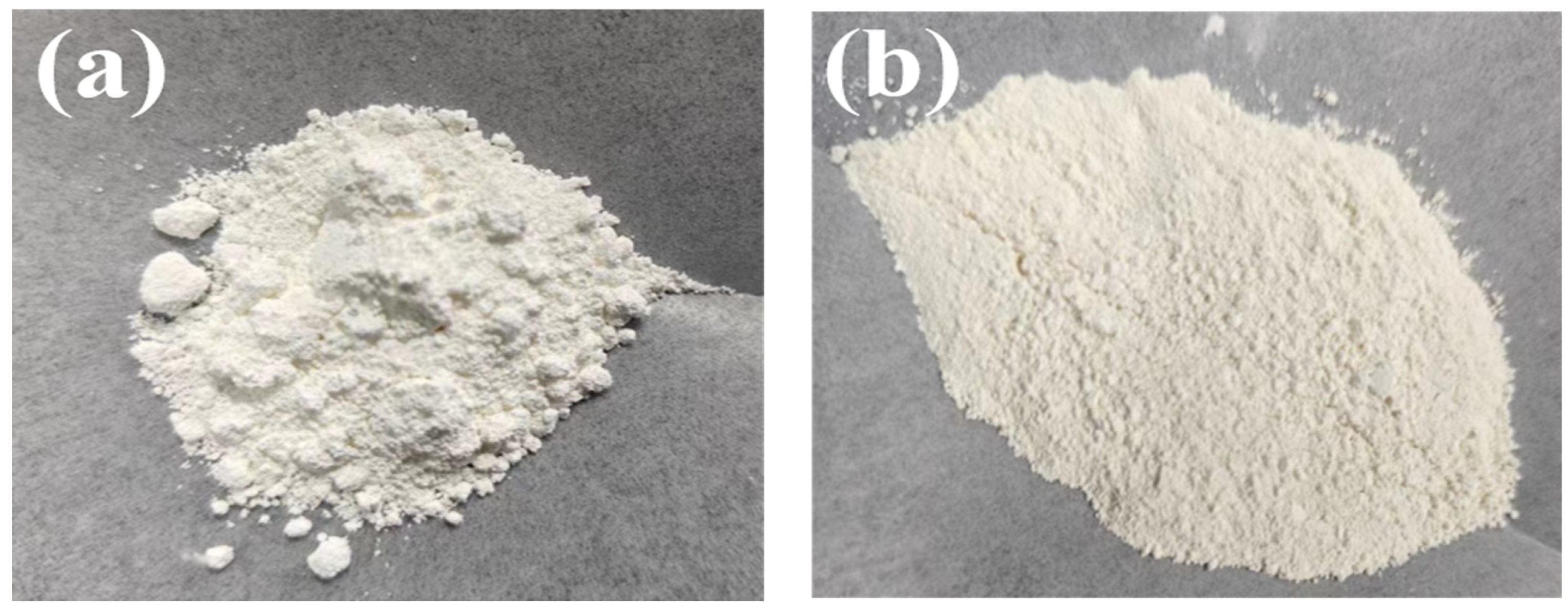
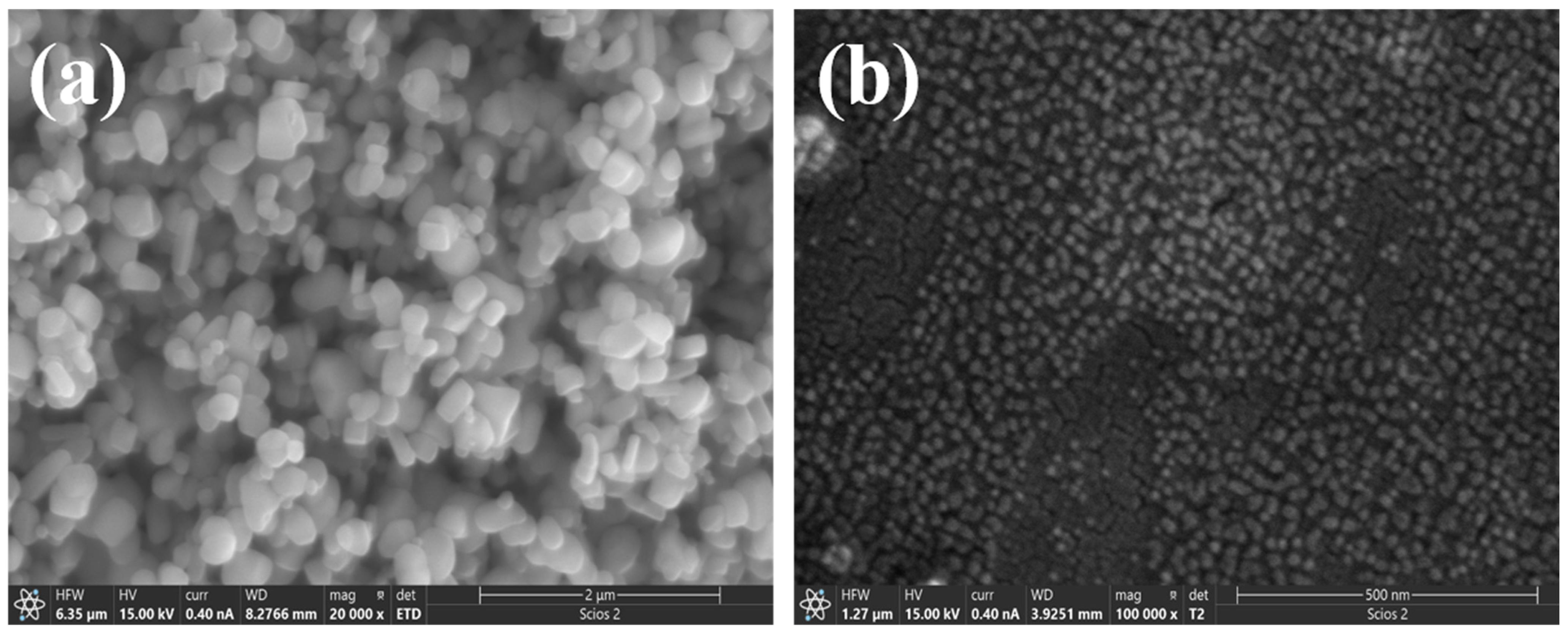
2.1. Experimental Materials

Experimental substrate: Q235 steel, industrial grade, China Baowu Iron & Steel Group Limited, (Shanghai, China); Titanium oxide (TiO2), 300~500 nm, industrial grade, Beijing Rong sheng Technology Co., Ltd. (Beijing, China); Aluminum dihydrogen phosphate [Al(H2PO4)3], −325 mesh, analytically pure, Shanghai McLean Biochemical Technology Co., Ltd. (Shanghai, China); Copper oxide (CuO), 10 nm, analytically pure, Shanghai Aladdin Biochemical Technology Co, Ltd. (Shanghai, China); alumina oxide (Al2O3), 13 μm, analytically pure, Shanghai Aladdin Biochemical Technology Co., Ltd. (Shanghai, China); Aluminum powder (Al), 30~50 μm, analytically pure, Shanghai Aladdin Biochemical Technology Co., Ltd. (Shanghai, China); Nickel powder (Ni), 20~40 μm, analytically pure, Shanghai Aladdin Biochemical Technology Co., Ltd. (Shanghai, China); CERAMO D-134C dispersant, industrial grade, Dai-ichi Kogyo Seiyaku Co., Ltd. (Tokyo, Japan) Deionized water, conductivity ≤ 1.0 μS/cm.

2.2. Experimental Methods

2.2.1. Aggregate Pretreatment

The TiO2 solution with 25% solid content was prepared by using industrial grade TiO2 and deionized water, and milled by the HLGB-10 nano compacting mill developed by the National Research Center for Ultrafine Powder Engineering Technology of Nanjing University of Science and Technology. During the pulverization process, the dispersant CERAMO D-134C (Dai-ichi Kogyo Seiyaku Co., Ltd., Tokyo, Japan) was continuously added to obtain a uniformly dispersed nano-TiO2 slurry, which was recorded as 25% nano-TiO2 slurry.
Subsequently, the nano-TiO2 powder was prepared by drying treatment, and the particle size and morphology of TiO2 before and after milling were tested by nano-particle size analyzer and scanning electron microscope (SEM). The particle size and morphology of industrial grade TiO2 and nano-TiO2 are shown in Figure 1 and Figure 2.
As shown in Figure 1, the industrial grade TiO2 before milling and the nano-TiO2 after milling were recorded by taking photos with a cell phone. Random samples were taken and observed with the naked eye, and the results showed that the technical grade TiO2 was fluffy with obvious agglomeration, while no agglomeration was observed in the milled nano-TiO2 powder. This macroscopic observation initially suggests that the particle size of technical grade TiO2 was significantly reduced under the action of the pulverizer.
The particle size distribution of TiO2 before and after milling was further tested by scanning electron microscopy (SEM), and the results are shown in Figure 2. Before milling, the particle size distribution of industrial grade TiO2 was wide (300~500 nm), the particle size was not uniform, and there was obvious agglomeration, which was consistent with the macroscopically observed agglomeration phenomenon, and the sample morphology was irregular. In contrast, the milled TiO2 nanoparticles had a significantly reduced particle size in the range of about 20 nm~30 nm, with a uniform distribution, more dispersed particles, a narrower size distribution, and a spherical-like morphology.
The aggregate components were precisely weighed according to the ratios specified in Table 1 and homogenized via stepwise mixing to ensure uniform dispersion of all constituents. In a 100 mL agate ball milling jar, the thoroughly mixed aggregates and grinding media were loaded at a mass ratio of 1:10 (aggregate to grinding media) and subjected to dry ball milling in a QM-2SP4 planetary ball mill. Zirconium oxide beads of 0.3 mm (ZrO2) served as the grinding medium, with the mill operated at a rotational speed of 300 rpm for 8 h. Post-milling, the samples were sieved through a 120-mesh standard sieve, and the sieved fractions were individually packaged in sealed.

2.2.2. Substrate Pretreatment

The Q235 steel substrate is cut into rectangular pieces of specifications 20 mm × 20 mm × 4 mm with consistent dimensions. The chemical composition is summarized in Table 2. The substrate surface was sanded sequentially using 400, 200, 100 mesh water-resistant sandpaper, using the criss-cross method of sanding, so that the surface maintains a large degree of roughness. The polished substrate was cleaned with deionized water, anhydrous ethanol and acetone in turn, and dried with a hair dryer for use.
Aluminum powder and nickel powder in the proportion of mass ratio = 7:3 sieve mixing uniformly, using simple compressed air sprayer, spray gun air pressure adjusted to 0.6~0.8 MPa, distance from the substrate 15~20 cm uniform spraying, multi-layer thin coating (each layer thickness ≤ 50 μm), 200~300 °C oven heat treatment for 1 h. Spraying an aluminum-nickel layer on the metal substrate can effectively prevent the coating from falling off, and the nickel-aluminum layer has a large roughness, which can improve the reaction between the ceramic aggregate and the substrate (transition layer), thus achieving the desired effect.
The metal substrate with the sprayed aluminum-nickel layer is washed in turn with deionized water, anhydrous ethanol, and acetone, and subsequently immersed in a beaker of anhydrous ethanol for use.

2.2.3. Preparation of Coating

Deionized water and aluminum dihydrogen phosphate powder were taken to formulate a solution of aluminum dihydrogen phosphate with a mass fraction of 50 wt%, and stirred thoroughly until it was completely dissolved, which was used as a binder.
The ball-milled aggregate components were weighed, added with deionized water and dispersed for 15 min using an ultrasonic disperser. Subsequently, the homogeneously dispersed aggregates were placed in a thermostatic magnetic stirrer for heating and stirring at a set speed of 600 rpm and a temperature of 100 °C. The temperature was set to 60 °C and the binder was slowly added to the aggregates.
When the temperature rose to 60 °C, the binder was slowly added to the aggregate at the ratio of aggregate to binder (g:mL) = 1:15. The temperature was maintained at 100 °C with stirring for 30 min. After stirring for 30 min, 20 mL of TiO2 nanoparticles with a mass fraction of 25 wt% were added to the slurry with continuous stirring and heating.
When the slurry became homogeneous and viscous, heating was stopped and it was left to cool.
After cooling, the treated metal substrate was taken out and the coating was applied manually by the slurry method. The coating process is maintained at a slow and uniform speed to ensure that the coating is flat and of uniform thickness, and to avoid large particles protruding. This prevents air from being trapped between the coating and the substrate and improves the densification of the coating.
After the coating was completed, the specimen was left to dry at room temperature for 24 h. Subsequently, the dried specimen was placed in a muffle furnace of KSL-1,200X (Hefei Kejing Material Technology Co., Ltd, Hefei, China), and heat treatment was carried out according to the set heating program.
Stage 1: The specimen was heated to 120 °C at a certain specific rate and held for 2 h to remove the free water and part of the water of crystallization that had not completely evaporated during the drying process of the coating.
Stage 2: The sample was heated to 400 °C at a certain specific rate and held for 1 h to further remove the remaining water of crystallization and to promote the intermolecular dehydration and condensation of the phosphate products [44].

2.2.4. Organizational Structure and Performance Test

In this study, a ZEISS EVO 15 scanning electron microscope (SEM) (Carl Zeiss AG, Oberkochen, Germany) was used to characterize the surface morphology and cross-section bonding of the ceramic coatings; a BRUKER D2 X-ray diffractometer (XRD) (Bruker Corporation, Manning Park Billerica, MA, USA) was used to analyze the physical composition of the coatings; and a J-2000 contact angle meter (Beijing Zhongyi Kexin Technology Co., Ltd, Beijing, China) was used to determine the rate of diffusion of the water traces on the surface of the coatings in order to assess the densification.
Coating Bonding Strength Test: The bonding strength of the coating itself and the shear strength between the coating and the substrate were determined by the lap method using an electronic tensile tester. As shown in Figure 3, Figure 3a illustrates the lap joint structure of the ceramic coated specimens, where 1 and 3 are metal samples with coatings, and 2 is epoxy resin adhesive; and in Figure 3b, both 1 and 2 are metal substrates. The specimens were cured after bonding and subjected to tensile testing on an electronic tensile testing machine to determine the shear strength, a value that can be used to characterize the bonding properties between the coating and the substrate, as well as the coating itself. The bond strength is calculated by the following Equation (1) [45]:
τ = P/(B ∗ L)
where τ is the bond strength of the specimen, MPa; P is the maximum load of the specimen for shear damage, N; B is the width of the specimen lap surface, mm; L is the length of the specimen lap surface, mm.
The abrasion resistance test was carried out by M-2000 friction and wear tester (Zhongte Testing Machine Co., Ltd, Jinan, China), and the uncoated Q235 steel (China Baowu Iron & Steel Group Limited, Shanghai, China)substrate was used as the comparison benchmark. The test parameters were set as follows: load 15 N, rotational speed 100 rpm, test time 30 min. SiC grinding wheels were used for the friction side, and the wear radius was 35 mm.
At the end of the experiment, the abraded specimens were removed after natural cooling and cleaned with acetone and blown dry by a hair dryer. The change in mass of the specimens before and after abrasion was measured by means of a precision balance, and the test was repeated three times for each sample, and the average value of the abrasion per unit area was calculated. The wear resistance of the material was characterized by the relative abrasion resistance (ε), which was calculated by the following Equation (2):
ε = M0/Mn
where ε is the relative wear resistance; M0 is the amount of wear of the standard specimen; Mn is the amount of wear of the tested specimen. The larger the relative wear resistance ε, the better the wear resistance of the material.
HXS 1,()000A Vickers microhardness tester (Beijing TIME High Technology Co. Ltd. Beijing, China) was used to test the microhardness of ceramic coatings under the following conditions: the test load was 200 g, the loading time was 15 s, and five test values were taken to calculate the average value.
Thermal shock resistance testing is used to evaluate the stability of a specimen in an environment of drastic temperature changes. When a coating undergoes alternating hot and cold changes, thermal stresses are generated within it, which may lead to cracking or peeling of the coating if the stresses exceed the coating’s tolerance limit. Therefore, the thermal shock resistance test can be used to directly evaluate the bonding performance between the coating and the substrate.
The failure of the coating is determined by observing whether the coating surface shows initial cracks, local buckling, or more than one-third of the macroscopic peeling. Experimental method: The prepared specimens were placed in a box-type resistance furnace, heated at 600 °C, 700 °C, 800 °C and kept for 10 min, then quickly transferred and cooled down to room temperature, and observed whether there were cracks, spalling or other damage on the surface. If there is no obvious damage to the surface of the specimen, the cycle of heating—rapid cooling—heating is continued until the coating fails, and the number of thermal shock cycles it can withstand is recorded.

3. Results and Discussion

3.1. Microscopic Morphology and Organizational Structure

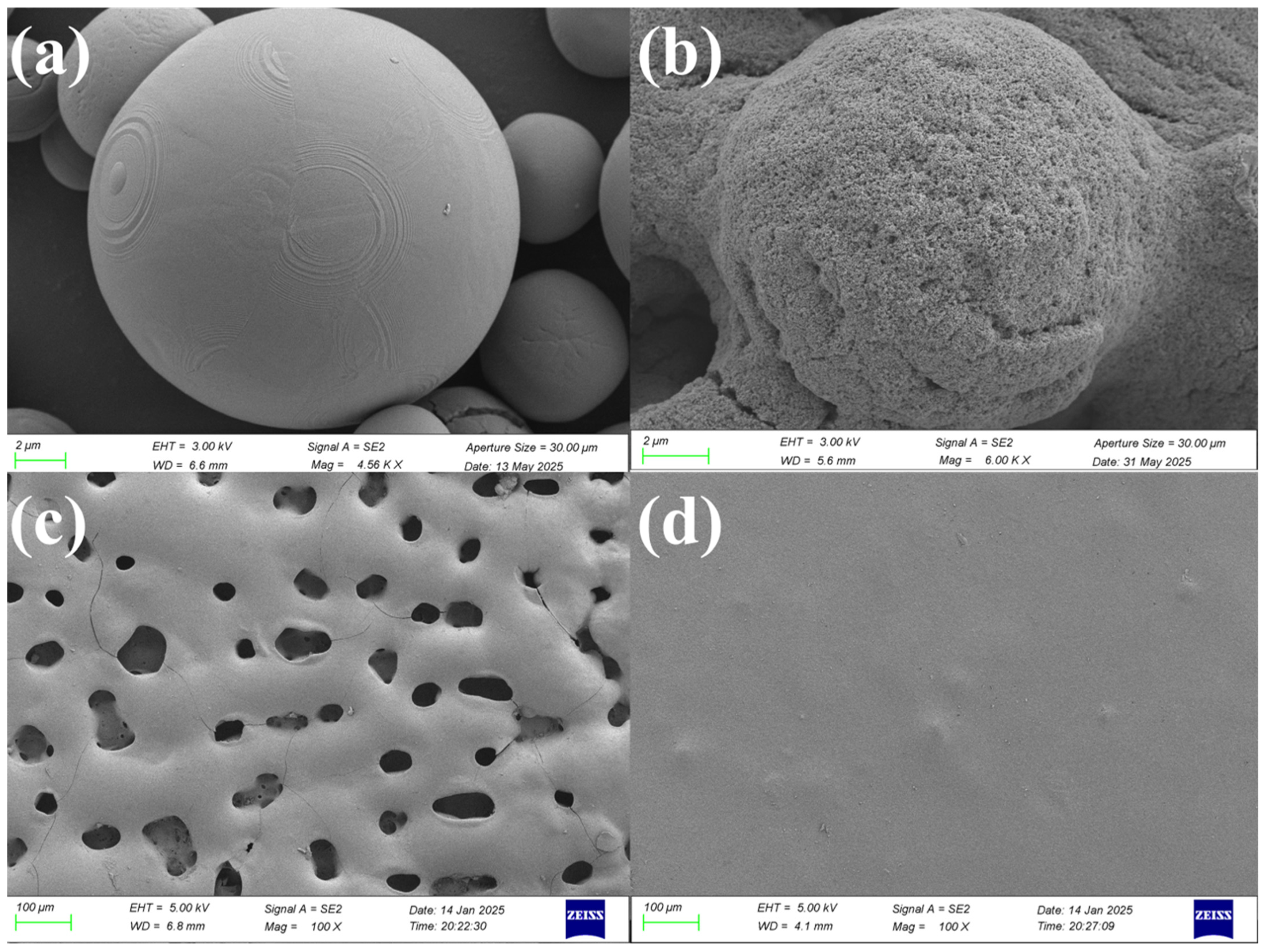
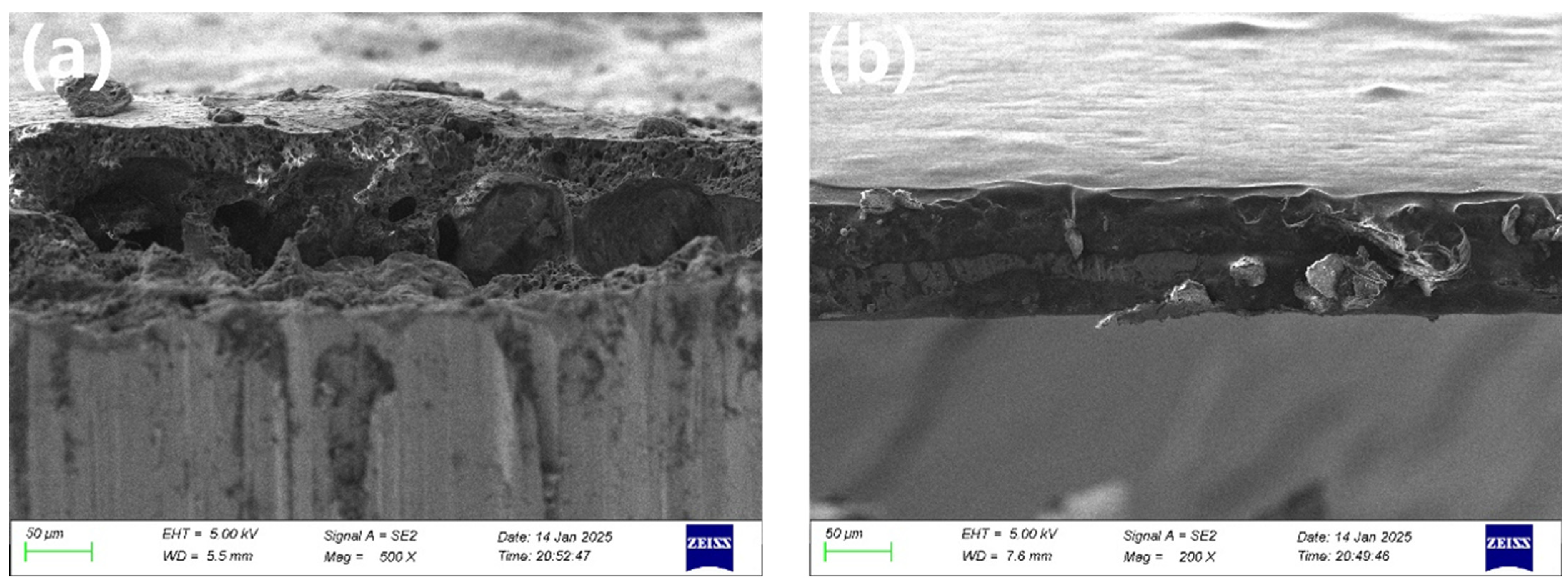
3.1.1. SEM Morphology Analysis of Ceramic Coatings

Scanning electron microscope (SEM) was used to analyze the microscopic morphology of the prepared TiO2/CuO composite modified Al2O3 microspheres and the sintered ceramic coating samples. Figure 4a,b show the alumina raw material and titanium oxide nanoparticles and copper oxide nanoparticles modified alumina, respectively. Figure 4c,d show the surface morphology of the ceramic coatings prepared by heating to 400 °C at different heating rates and holding for 1 h. The cross-section morphology of the coatings is shown in Figure 5, which further reveals their organizational structure and interfacial bonding.
Figure 4a depicts the 13 μm aluminum trioxide raw material, while Figure 4b illustrates the alumina modified with nano-TiO2 and nano-CuO. The surface of the modified aluminum trioxide is evenly coated, and the nano-TiO2 and nano-CuO particles are uniformly distributed on its surface, forming a well-defined core-shell structure. In Figure 4c, the ceramic composite coating prepared by warming up to 400 °C at 5 °C/min and holding temperature for 1 h has large pores on the surface, uneven size distribution of ceramic particles, rough surface and poor densification. Figure 4d shows that after the ceramic coating is warmed up to 400 °C at 2 °C/min and held at 400 °C for 1 h, the pores on the surface basically disappeared, the particles are uniformly distributed, the surface is relatively flat, and the densification is obviously improved.
The defects such as porosity in ceramic coating are mainly attributed to the following two factors:
(1)
Insufficient room temperature drying time. After the coating is prepared, it needs to be dried at room temperature to remove the free moisture inside the coating. However, if the drying time is insufficient, the residual liquid moisture evaporates too quickly during the high-temperature curing process, making it easy to form air bubbles, which can create porosity inside and on the surface of the coating.
(2)
Influence of temperature rise rate. If the initial temperature rise rate is too fast during the curing process, it will easily lead to the formation of pores and cracks. The main reason for this is that the free water that is not completely removed from the coating is violently evaporated during the rapid temperature rise, resulting in the formation of tiny pores within the coating. To avoid this problem, a lower temperature is usually used to slowly increase the temperature, so that the coating is fully cured in the low-temperature stage, thus reducing the generation of pores and improving the densification of the coating.
Figure 5a,b show the cross-sectional morphology of ceramic coatings prepared at different heating rates (5 °C/min and 2 °C/min). As can be seen in Figure 5a, the cross-section of the coating sintered at 5 °C/min heating rate is more disordered, and there are obvious pores; in contrast, the cross-section of the coating obtained at the 2 °C/min heating rate corresponding to Figure 5b is more regular, and no obvious voids or bubbles can be observed.
In addition, from the cross-sectional morphology analysis, the ceramic coatings prepared at different heating rates are tightly bonded with the metal substrate, but there is a clear interfacial demarcation line between the two, which indicates that no fusion welding phenomenon has occurred. At the same time, the diffusion behavior of the ceramic coating to the metal substrate did not occur, indicating that it mainly relies on the mechanical bonding force attached to the surface of the substrate [46,47]. Based on the above analysis, the current low sintering temperature only achieved the curing of the coating and its mechanical adhesion to the surface of the metal substrate.

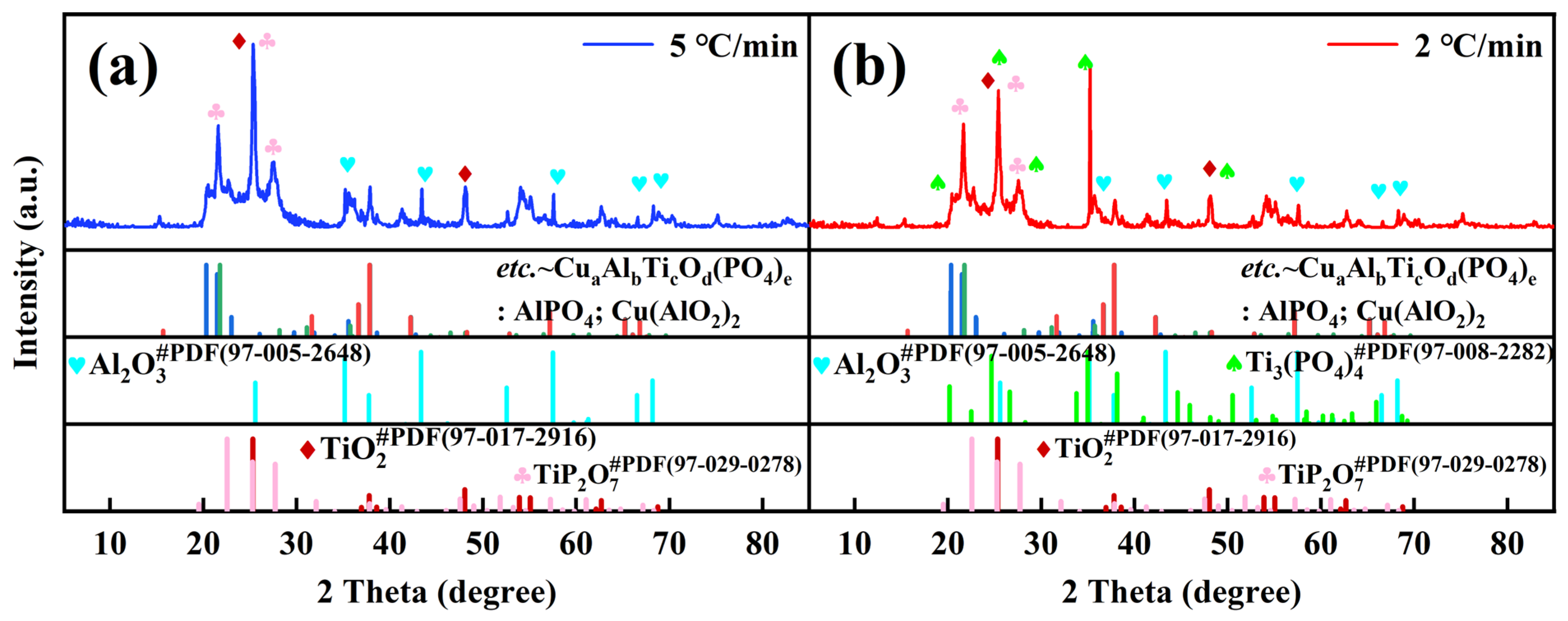
3.1.2. X-Ray Analysis of Ceramic Coatings

During the curing process, the ceramic components of the nano-TiO2 composite coatings may undergo chemical reactions, which may affect their phase composition and properties. In order to investigate whether new phases are generated after curing at 400 °C and the effect of different temperature increase rates on the properties of ceramic coatings, the physical phases of the coatings were analyzed by X-ray diffraction (XRD) in this study.
As shown in Figure 6, by comparing the PDF standard cards (TiO2 (PDF#97-017-2916); Al2O3 (PDF#97-005-2648); Al(PO4) PDF#97-028-0308); TiP2O7 (PDF#97-029-0278); Ti3(PO4)4(PDF#97- 008-2282); Cu(AlO2)2 (PDF#97-003-1701)) show that the modified TiO2 nanocomposite ceramic coatings at 2θ = 20.3°, 22.5°, 25.3°, 34.9°, 37.8°, 43.3° in order of Al(PO4) (−2 1 3), TiP2O7 (2 0 0), TiO2 (1 0 1), Ti3(PO4)4 (1 1 2), Cu(AlO2)2 (0 1 2), and Al2O3 (1 1 3) major crystalline peaks [48,49,50,51,52,53].
After sintering at 400 °C for 1 h under two heating rates of 5 °C/min and 2 °C/min, the formed phase compositions of the TiO2 nanocomposite ceramic coating showed slight differences. New phases of aluminum phosphate (AlPO4), titanium pyrophosphate (TiP2O7), and a small amount of Cu(AlO2)2 were detected under both heating rates. This phenomenon indicates that the following main chemical reactions occurred in the coating components at 400 °C: Formation of aluminum phosphate (AlPO4)**: Under high-temperature, aluminum dihydrogen phosphate (Al(H2PO4)3) decomposed, and its H2PO4 ions combined with Al3+ to form aluminum phosphate (AlPO4); Formation of titanium pyrophosphate (TiP2O7)**: Nano-TiO2 reacted with phosphoric acid to generate titanium pyrophosphate (TiP2O7), which indicates that TiO2 underwent a certain degree of phase transformation during the sintering process. Notably, a new phase of titanium phosphate (Ti3(PO4)4) was formed in the coating prepared at a heating rate of 2 °C/min. This phase exhibits excellent high-temperature resistance and can maintain good chemical stability in high-temperature environments. This characteristic confirms that coatings prepared at lower heating rates show better adaptability to high-temperature conditions [53].
In addition, at a sintering temperature of 400 °C, some unreacted nano-TiO2 and Al2O3 particles still exist in the coating. During the cooling process, excessive TiO2 will pre-precipitate from the coating, thereby affecting the final microstructure.
In summary, for the ceramic coatings prepared by the slurry method at 400 °C, the ceramic aggregates mainly react with the aluminum phosphate binder, while no obvious chemical reaction occurs between the coating and the substrate. This indicates that the coating is mainly attached to the surface of the substrate through mechanical bonding force.

3.2. Analysis of Coating Performance Test

3.2.1. Coating Densification Analysis

The densification test results of the ceramic coatings are shown in Table 3. From the data, different heating rates have a significant effect on the densification of the coating: the ceramic coating with a heating rate of 5 °C/min started to diffuse water traces at 8 min; the ceramic coating with a heating rate of 2 °C/min delayed the diffusion phenomenon until 20 min.
Combined with Figure 4b, the surface of the ceramic coating prepared by 2 °C/min heating up is more flat and has better densification, and no obvious defects such as pores are observed. This shows that the slower heating rate can help to improve the structural uniformity and densification of the coating.
In addition, the nano-TiO2 in the formulation plays a key role in improving the densification of the coating. Except for the nano-TiO2, the rest of the components were mainly composed of a small number of micron-sized particles. Since the size of nanoparticles is much smaller than that of micron particles, they can effectively fill the pores between larger particles, thus reducing the porosity of the coating surface and improving the densification of the coating [54,55].

3.2.2. Coating Abrasive Wear Test

The results of the abrasive wear tests are shown in Table 4, which shows that the introduction of the coating significantly improves the wear resistance of the material. Compared with the base material, the relative wear resistance (ε) of the ceramic coatings is increased, of which: the coating prepared at a temperature increase rate of 5 °C/min increases the relative wear resistance by a factor of 1.36, and the coating prepared at a temperature increase rate of 2 °C/min increases the relative wear resistance by a factor of 1.89.
At the same time, a lower heating rate (2 °C/min) helps to further improve the wear resistance of the coating, indicating that a reasonable control of the heating rate plays an important role in optimizing the wear resistance of ceramic coatings. In the process of preparing ceramic coatings with a heating rate of 2 °C/min, the free and bound water molecules inside the coating can be released in a slow and orderly manner, which promotes the densification of the coating and enhances the toughness and strength of its organizational structure at the same time. This optimization process improves the wear resistance of the coating, which is one of the fundamental reasons for the significant increase in its relative wear resistance.
In addition, nanoparticles themselves have excellent properties such as high plasticity, high hardness, high-temperature resistance, and wear resistance. In the coating system, the design of nanoparticles as the main part and micron particles as the secondary part helps to inhibit the growth of micron-sized matrix grains, thus realizing the homogenization of the coating organization, improving its densification and reducing the formation of holes. Nanoparticles not only play a filling role in the coating, effectively improving the densification degree of the coating, but also play a “pinning” and “bridging” effect in the wear process [56,57].
This mechanism can inhibit crack expansion and effectively reduce the exfoliation of large particles during the wear process, thus improving the wear resistance of the coating.

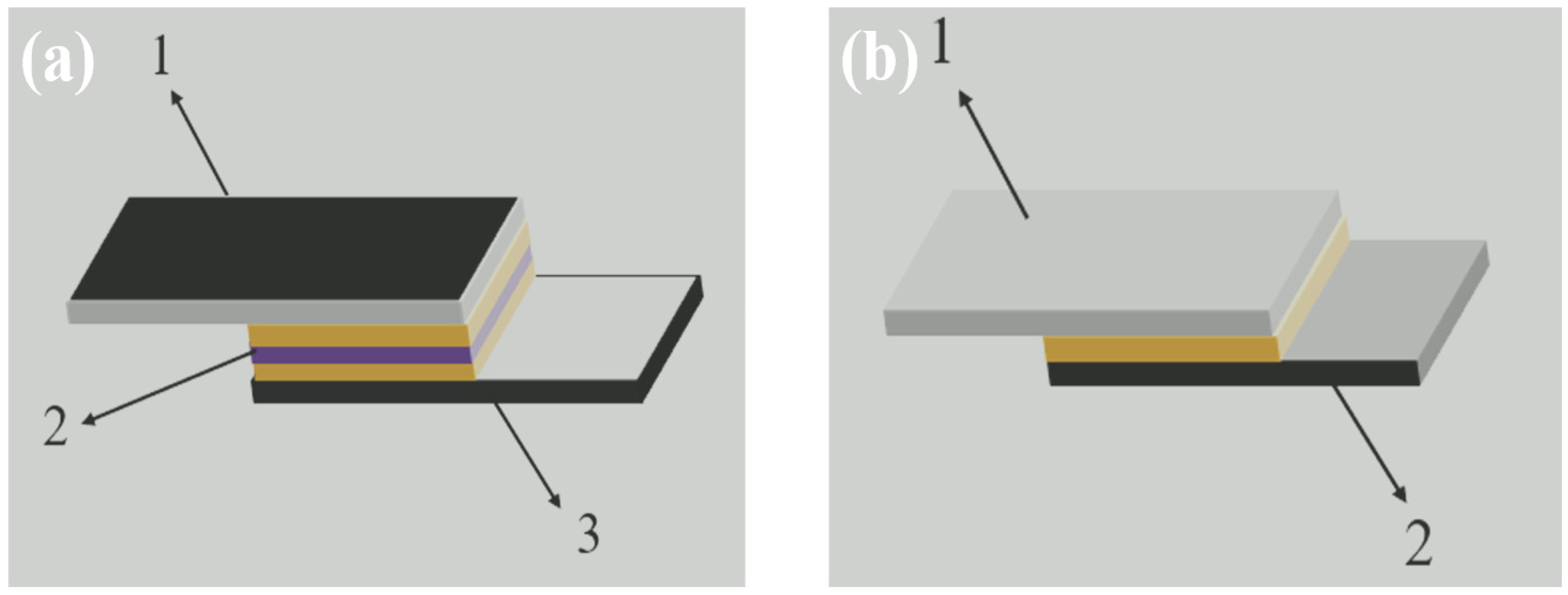
3.2.3. Coating Shear Strength Analysis

The fracture behavior of ceramic coatings under tensile loading may exhibit different failure modes, typically characterized by: (1) interfacial failure at the substrate-coating interface, (2) cohesive failure within the coating, or (3) mixed-mode failure involving both coating and substrate materials. This study systematically evaluated the bonding strength of ceramic coatings cured at 400 °C. Test specimens were prepared according to two lap joint configurations shown in Figure 3a,b. Shear strength testing was conducted using an electronic universal testing machine. Figure 3a was employed to characterize the adhesive properties between the coating and substrate, while Figure 3b was used to evaluate the cohesive properties of the coating itself. The corresponding test results are presented in Table 5.
From the experimental data, in the specimens cured at 400 °C, the shear strength of the coating itself with a temperature increase rate of 5 °C/min was lower, while the shear strength of the coating with a temperature increase rate of 2 °C/min was significantly higher. The analysis shows that under the conditions of a temperature increase rate of 5 °C/min and a curing temperature of 400 °C, the internal structure of the coating is more loose and porous, resulting in insufficient bonding between the ceramic particles, which reduces the bonding strength of the coating.

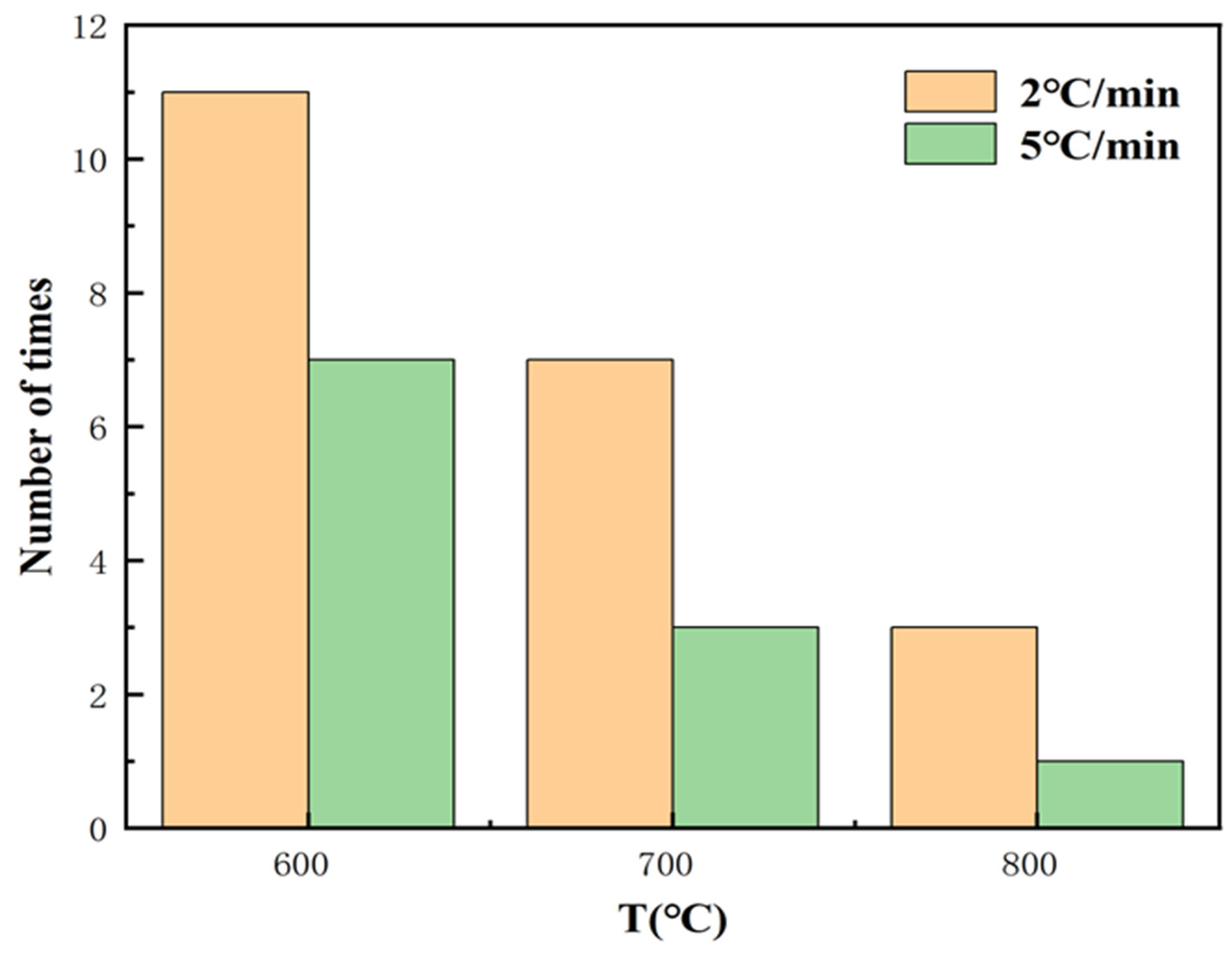
3.2.4. Coating Thermal Shock Resistance Test

As can be seen in Figure 7, the number of thermal shock cycles of the specimens decreases gradually with the increase of thermal shock temperature. Among them, the number of thermal shock cycles of the specimens reaches the maximum at 600 °C thermal shock temperature and the minimum at 800 °C thermal shock temperature. In addition, the composite ceramic coating with a heating rate of 2 °C/min showed superior thermal shock resistance compared to the coating with a heating rate of 5 °C/min. The composite coating with a 2 °C/min ramp rate had the highest number of thermal shock cycles under the 600 °C test condition, while the coating with a 5 °C/min ramp rate had the lowest number of thermal shock cycles under the 800 °C test condition. This suggests that a lower temperature increase rate may help to improve the thermal shock resistance of ceramic coatings.
The thermal shock resistance of a coating is not only affected by the coefficient of thermal expansion of the substrate itself but is also closely related to the bond strength between the coating and the substrate. In general, the coefficient of thermal expansion of metallic substrates is usually larger than that of non-metallic oxides. Among them, the thermal expansion coefficients of Al2O3 are relatively close to those of the metal matrix, while the thermal expansion coefficients of TiO2 differ greatly from those of the metal matrix, and the surface of nano-TiO2 contains unsaturated bonds and hydroxyl groups in different bonding states, which gives it high surface activity, thus promoting the chemical reaction of the ceramic coating during the curing process, and the new substances generated further enhance the bonding strength of the coating [58]. In addition, the coefficient of thermal expansion of nanocrystalline materials is usually more than one times higher than that of micrometer crystalline materials, so replacing micrometer particles with nanoceramic particles can effectively increase the coefficient of thermal expansion of the coatings and reduce the thermal stresses between the coatings and the substrate, thus improving the thermal shock resistance of the coatings [59].
The experimental results show that the pore structure at the coating interface has an important effect on thermal shock resistance. Coatings with a small number of micropores at the interface show superior thermal shock resistance compared to coatings with large pores. This may be due to the fact that micropores can effectively relieve stress concentration and reduce crack extension during thermal shock, thus improving the thermal shock stability of the coating. However, coatings prepared at a 5 °C/min heating rate tended to form more large pores, which not only reduced the bonding strength of the ceramic coatings to the substrate, but also provided penetration channels for corrosive atmospheres and accelerated oxidization reactions at the interfaces, thus weakening the thermal shock resistance of the coatings. This phenomenon further suggests that reducing the heating rate can help optimize the densification of the coating and enhance its thermal shock resistance.

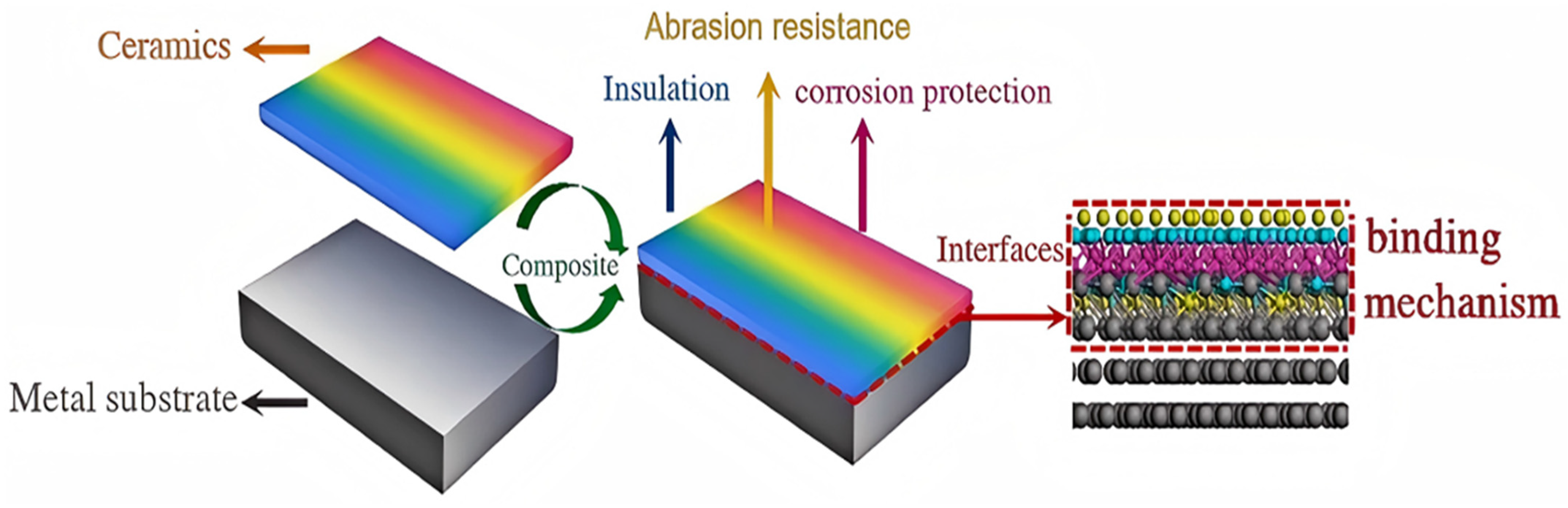
3.3. Ceramic-Metal Interface Analysis

The preparation of ceramic coatings for metal substrates refers to the formation of ceramic coatings with certain functionality on the surface of metal substrates by means of technical deposition, or high-temperature oxidation, or chemical adsorption, as shown in Figure 8. The metal-ceramic interface structure is a typical heterogeneous interface. Due to the large differences in the chemical properties of heterogeneous material surfaces and the complexity of the interface formation process, the metal-ceramic interfacial structure presents a variety of combination types.
According to whether a chemical reaction occurs at the metal-ceramic interface, the interfacial bonding can be categorized into three types: mechanical bonding, reaction bonding, and diffusion bonding. Combined with the cross-sectional morphology and XRD analysis of the nano-TiO2 ceramic coating shown in Figure 5 in the previous section, it can be observed that the interface between the nano-TiO2 ceramic coating and the Q235 steel has a clear boundary and is mainly dominated by mechanical bonding. Mechanical bonding refers to the physical bonding mode formed by metal and ceramic relying on the mechanical interlocking effect of surface rough fibers. In this bonding mode, there is neither a chemical reaction nor atomic diffusion between the matrix and ceramic reinforced phase, and the interface structure is clear and flat. However, due to the low strength of the interfacial connection, this structure is prone to interfacial fracture under external forces. This phenomenon has been fully verified in previous bonding performance test results [60].
The mechanical interlocking mechanism suggests that at the metal-ceramic interface, the irregularity of the substrate surface can significantly increase the contact area between the adhesive or ceramic particles and the substrate, thus enhancing the interfacial bond strength [61]. The higher the roughness of the surface, the stronger the mechanical interlocking effect. This theory can explain why the adhesive force of the coating interface is strongly influenced by the surface finish of the substrate. In addition, physisorption (intermolecular forces such as van der Waals forces and hydrogen bonding) plays a key role in the adhesion process of ceramic coatings. For example, phosphate adhesives can effectively adhere to a wide range of materials due to their intermolecular forces [62]. Copper oxide (CuO) in the ceramic component reacts chemically with the phosphate adhesive to form an inorganic polymer network structure that stabilizes the metal oxide particles in the ceramic coating. In addition, the macromolecules of the adhesive can be bonded to each other through hydrogen and ionic bonds, further enhancing the interfacial bonding strength.
It is worth noting that the adhesive not only binds to the substrate through physical adsorption but may also react chemically with the metal surface to form chemical bonds. For example, when the adhesive is used for the bonding of metal workpieces such as iron and aluminum, metal surface substitution reactions may occur, so that the cured adhesive and the metal substrate penetrate into each other, thus enhancing the adhesion [63]. Therefore, in order to ensure the effective bonding between the adhesive and the substrate, it is necessary to ensure that it is in full contact with the surface of the substrate, which requires the improvement of the interfacial bonding quality through appropriate surface treatment processes (e.g., solvent cleaning, polishing, and abrasion roughening, etc.) [64].
Nanoparticles are susceptible to chemisorption with metal surfaces, which is mainly attributed to the high surface energy of the nanoparticles, the high activity of the surface atoms, and the surface defects of the metal substrate [65]. Nanoparticles, due to their small size and high curvature, are able to enhance the interfacial contact tightness, allowing the weak interaction forces to exhibit locally a bonding strength similar to that of chemical bonds. Based on this principle, Nieto-Maestre in a study conducted at the National Center for Energy Development of Spain, succeeded in the preparation of Al2O3 particles on the surface of a Fe-based heat storage tank by introducing the reinforcing heat transfer agent nanoparticles into the Fe-based vessel surface. Al2O3-Fe composites were prepared, which further validated the mechanism of nanoparticles in metal-ceramic interfacial bonding [66].
In summary, metal-ceramic interfacial bonding mainly relies on mechanical interlocking, physical adsorption, and chemical bonding mechanisms. The optimization of the coating bonding strength can be achieved by adjusting the surface roughness of the substrate, enhancing the chemical adsorption, and introducing nanoparticles to improve the stability and durability of the metal-ceramic interface. Thus, the ideal metal-ceramic interface system should have the following requirements: (i) excellent bonding strength between ceramics and substrate; (ii) small diffusion coefficients between the two phases of the interface; (iii) similar thermomechanical and physical parameters between ceramics and substrate; and (iv) moderate thickness of the interface with good mechanical properties, which can absorb the residual stress and inhibit the growth of cracks.

4. Conclusions

Building upon the exceptional properties of nanomaterials, this study innovatively proposes a synergistic reinforcement strategy involving the encapsulation of Al2O3 by nano-TiO2. Through the precise design of a core-shell structure consisting of 65 wt% nano-TiO2 encapsulating 30 wt% micron-sized Al2O3, the mechanical properties of the coating, such as hardness and toughness, are further enhanced via dispersion strengthening and fine-grain strengthening mechanisms. Leveraging the high chemical stability of nano-TiO2 and the high strength of Al2O3, this approach achieves a complementary optimization of material performance.
During the fabrication process, a low-temperature sintering technique at 400 °C was employed to deposit the nanoceramic coating on Q235 steel substrates using a slurry method. This process significantly diverges from traditional high-temperature approaches, dramatically reducing energy consumption and process complexity while effectively preventing microstructural degradation of the substrate caused by high temperatures. During coating formation, an interfacial metallurgical bonding process establishes a submicron-scale reinforcement network. This unique microstructure not only endows the coating with excellent wear resistance but also enhances its overall mechanical performance through synergistic interactions between the reinforcing phase and the matrix.
In-depth analysis of the bonding mechanism reveals that the interface between the nanocomposite coating and the metal substrate is primarily formed through mechanical interlocking, resulting in a robust physical bond. This bonding method ensures high interfacial strength while imparting a certain degree of deformation compatibility, enabling the coating to maintain stable performance under complex working conditions. With broad application prospects in marine engineering, automotive manufacturing, and aerospace industries, this research provides solid theoretical and technical guidance for the process optimization and engineering application of metal-based ceramic coatings, holding significant importance for driving technological advancements in related industries.

Author Contributions

Conceptualization, S.M.; Data curation, J.C.; Formal analysis, G.C.; Funding acquisition, J.L.; Investigation, K.D.; Methodology, J.C. and S.M.; Project administration, J.L.; Resources, K.D.; Supervision, J.L.; Validation, G.C.; Writing—original draft, Y.L.; Writing—review and editing, Y.Z. and Y.L. All authors have read and agreed to the published version of the manuscript.

Funding

This research received no external funding.

Institutional Review Board Statement

Not applicable.

Informed Consent Statement

Not applicable.

Data Availability Statement

The data presented in this study are available on request from the corresponding author. The data are not publicly available due to privacy.

Conflicts of Interest

Author Jiaqi Cao was employed by the company CITIC Heavy Industries (Beijing) New Energy Material Technology Company. The remaining authors declare that the research was conducted in the absence of any commercial or financial relationships that could be construed as a potential conflict of interest.

References

  1. Salman, S.; Köse, R.; Urtekin, L.; Findik, F. An investigation of different ceramic coating thermal properties. Mater. Des. 2006, 27, 585–590. [Google Scholar] [CrossRef]
  2. Zang, D.M.; Xun, X.W. Ceramics Coated Metallic Materials: Methods, Properties and Applications. In Advanced Ceramic Materials; Intech Open: London, UK, 2020. [Google Scholar] [CrossRef]
  3. Li, C.; Shi, J.; Li, Y.H.; Li, Y.F.; Gao, Y.M.; Li, B.; Goei, R.; Cheng, C.Y.; Zhao, S.Y.; Tok, A.I.Y. Interfacial bonding and abrasive wear behaviours of the iron matrix composites. Mater. Sci. Technol. 2022, 38, 965–976. [Google Scholar] [CrossRef]
  4. Fedrizzi, L.; Rossi, S.; Cristel, R.; Bonor, P.L. Corrosion and wear behaviour of HVOF cermet coatings used to replace hard chromium. Electrochim. Acta 2004, 49, 2803–2814. [Google Scholar] [CrossRef]
  5. Wang, Y.; Tian, W.; Zhang, T.; Yang, Y. Microstructure, spallation and corrosion of plasma sprayed Al2O3–13%TiO2 coatings. Corros. Sci. 2009, 51, 2824–2931. [Google Scholar] [CrossRef]
  6. Yu, J.J.; Liu, S.Y.; Li, F.; Wang, T.H. Na2SiO3/Al2O3 composite coatings on 304 stainless steels for enhanced high temperature oxidation inhibition and chloride-induced corrosion resistance. Surf. Coat. Technol. 2017, 309, 1089–1098. [Google Scholar] [CrossRef]
  7. Qin, D.C.; Xu, G.Y.; Yang, Y.; Chen, S. Multiphase ceramic coatings with high hardness and wear resistance on 5052 aluminum alloy by a microarc oxidation method. ACS Sustain. Chem. Eng. 2018, 6, 2431–2437. [Google Scholar] [CrossRef]
  8. Cheng, W.J.; Wang, J.J.; Ma, X.; Liu, P.; Liaw, P.K.; Li, W. A review on microstructures and mechanical properties of protective nano-multilayered films or coatings. J. Mater. Res. Technol. 2023, 27, 2413–2442. [Google Scholar] [CrossRef]
  9. Zhao, D.; Gutmark, E.; De Goey, P. A review of cavity-based trapped vortex, ultra-compact, high-g, inter-turbine combustors. Prog. Energy Combust. Sci. 2018, 66, 42–82. [Google Scholar] [CrossRef]
  10. Liu, Y.; Lei, J.; Deng, X.; Liu, Y.; Sun, D.; Zhang, Y. Research and analysis of a thermal optimisation design method for aluminum alloy pistons in diesel engines. Case Stud. Therm. Eng. 2023, 52, 103667. [Google Scholar] [CrossRef]
  11. Qin, B.B.; Ma, L.Q.; Wang, S.C.; Hou, C.J.; Zhou, S.G. Construction of a sandwich-like Gr/Ni composite coating on AZ91D magnesium alloy to achieve excellent corrosion and wear resistances in the seawater. Diam. Relat. Mater. 2022, 130, 109400. [Google Scholar] [CrossRef]
  12. Pei, W.L.; Pei, X.L.; Xie, Z.Z.; Wang, J.M. Research progress of marine anti-corrosion and wear-resistant coating. Tribol. Int. 2024, 198, 109864. [Google Scholar] [CrossRef]
  13. Song, X.; Liu, F.; Yan, Y.; Wang, W.; Wang, Y.; Sun, W.; Cui, J. Influence of surface roughness of thermal barrier coating on the cooling performance of a film-cooled turbine vane. Case Stud. Therm. Eng. 2025, 65, 105698. [Google Scholar] [CrossRef]
  14. Padture, N.P.; Gell, M.; Jordan, E.H. Thermal barrier coatings for gas-turbine engine applications. Science 2002, 296, 280–284. [Google Scholar] [CrossRef]
  15. Chen, D.C.; He, L.P.; Shang, S.P. Study on aluminum phosphate binder and related Al2O3-SiC ceramic coating. Mater Sci. Eng. A-Struct Mater Prop Microstruct. Process 2003, 348, 29–35. [Google Scholar] [CrossRef]
  16. Guo, R.F.; Shen, P.; Li, S.X.; Shaga, A.; Jiang, Q.C. High compressive strength in nacre-inspired Al-7Si-5Cu/Al2O3-ZrO2 composites at room and elevated temperatures by regulating interfacial reaction. Ceram. Int. 2017, 43, 7369–7373. [Google Scholar] [CrossRef]
  17. Zhang, Z.; Zhou, J.; Zhou, J.; Zhu, J.; Wang, A.Z.; Zhou, Q. Research progress on preparation technology and failure mechanism of metal/ceramic laminated composites. J. Aeronaut. Mater. 2020, 40, 33–44. [Google Scholar] [CrossRef]
  18. Chen, B.S.; Meng, J.S.; Wang, Y.; Shi, X.P. Research progress on preparation technology and coating of nano-powder by plasma spraying. Heat Treat. Met. 2023, 48, 223–236. [Google Scholar] [CrossRef]
  19. Xiao, Y.; Xiong, J.; Guo, Z.X.; Liu, J.B.; Zhou, L.M.; Ye, J.L.; Zhao, W. Microstructures and properties of PVD TiAlN coating deposited on ceramets with different Ti (C, N) grain size. J. Cent. South Univ. 2020, 27, 721–735. [Google Scholar] [CrossRef]
  20. Geng, M.Z.; Wang, W.Q.; Zhang, X.G. Microstructures and Properties of Ni/Ti(C,N) Composite Cermet Coating Prepared by Electro-spark Deposition. Surf. Technol. 2020, 49, 222–229. [Google Scholar] [CrossRef]
  21. Yang, J.H.; Zhang, W.; Gao, X.M.; Zhang, Q.L. Study of Fe-Ni(Cr) Alloy and Nano-Al2O3 Particles Composite Coating Prepared by Laser Cladding. Solid State Phenom. 2006, 118, 585–590. [Google Scholar] [CrossRef]
  22. Tian, Z.J.; Gao, Y.W.; Wang, D.S.; Shen, L.D.; Liu, Z.D.; Gao, X.S.; Huang, Y.H. Hot Corrosion Behavior of Laser-remelted Nanostructured Ceramic Coatings on TiAl Alloy Surface. Appl. Laser 2010, 30, 73–79. [Google Scholar] [CrossRef]
  23. Xiao, K.; Xue, W.; Li, Z.L.; Wang, J.R.; Li, X.M.; Dong, C.F.; Wu, J.S.; Li, X.G.; Wei, D. Effect of sintering temperature on the microstructure and performance of a ceramic coating obtained by the slurry method. Ceram. Int. 2018, 44, 11180–11186. [Google Scholar] [CrossRef]
  24. Zhang, Z.F.; Chen, H.; Wang, Y.Q.; Wang, G.; Li, L.H.; Zhong, M.; Bai, H. Effect of sodium silicate binder on the performance of ceramic coatings on copper prepared by the slurry method. Surf. Coat. Technol. 2022, 448, 128868. [Google Scholar] [CrossRef]
  25. Wang, J.Q.; Yuan, Y.C.; Chi, Z.H.; Zhang, G.X. High-temperature sulfur corrosion behavior of h-BN-based ceramic coating prepared by slurry method. Mater. Chem. Phys. 2018, 206, 186–192. [Google Scholar] [CrossRef]
  26. Chen, Q.; Kang, S.H.; Li, Z.P.; Tang, J.G.; Deng, Y.L.; Chen, M.A. Effect of changes in organo-silicon electrolyte concentration and composition on SiO2 ceramic coating prepared by plasma electrolytic oxidation on 6061 aluminum alloy. Ceram. Int. 2024, 50, 29920–29936. [Google Scholar] [CrossRef]
  27. Yang, Q.B.; Sang, S.B.; Yang, F.Y.; Li, Y.W.; Zhu, T.B.; Wang, H. Influence of Al2O3 content on microstructure and oxidation resistance of glass-ceramic coatings for 06Ni9DR alloy steel. Ceram. Int. 2024, 50, 48788–48798. [Google Scholar] [CrossRef]
  28. Jiang, J.P.; Chen, Y.N.; Jiang, C.P.; Zhang, Y.; Zhao, Q.Y.; Zhang, Z.; Yang, Z.H.; Wang, S.P.; Li, H.Z. Composite ceramic coating with enhanced thermal shock resistance formed by the in-situ synthesis of nano-ZrO2. Ceram. Int. 2022, 48, 10629–10637. [Google Scholar] [CrossRef]
  29. Peng, W.D.; Chen, Z.; Yan, W.; Chen, J.F.; Li, G.Q.; Li, Y.W. Microstructure and properties of ceramic filter containing porous MgO coating and its filtration of Al2O3 inclusions in molten steel. Ceram. Int. 2024, 50, 218–229. [Google Scholar] [CrossRef]
  30. Wu, H.B.; Zhang, X.Y.; Geng, Z.H.; Yin, Y.; Hang, R.Q.; Huang, X.B.; Yao, X.H.; Tang, B. Preparation, antibacterial effects and corrosion resistant of porous Cu–TiO2 coatings. Appl. Surf. Sci. 2014, 308, 43–49. [Google Scholar] [CrossRef]
  31. Huang, L.J.; Jing, S.L.; Zhuo, O.; Meng, X.F.; Wang, X.Z. Surface hydrophilicity and antifungal properties of TiO2 films coated on a Co-Cr substrate. BioMed Res. Int. 2017, 2017, 2054723. [Google Scholar] [CrossRef]
  32. Krishna, D.S.R.; Sun, Y. Thermally oxidized rutile-TiO2 coating on stainless steel for tribological properties and corrosion resistance enhancement. Appl. Surf. Sci. 2005, 252, 1107–1116. [Google Scholar] [CrossRef]
  33. Procopio, A.M.S.; Carvalho, J.D.L.; Silveira, T.H.R.; Valério, A.L.; Vaz, I.C.F.; Cabral, A.C.T.; Freitas, M.R.; Silva, M.C.; Filho, F.M. CeO2 thin film supported on TiO2 porous ceramics. Mater. Lett. 2020, 276, 128224. [Google Scholar] [CrossRef]
  34. Emarati, S.M.; Mozammel, M. Efficient one-step fabrication of superhydrophobic nano-TiO2/TMPSi ceramic composite coating with enhanced corrosion resistance on 316L. Ceram. Int. 2020, 46, 1652–1661. [Google Scholar] [CrossRef]
  35. Lakkimsetty, N.R.; Mai, A.A.; Joy, V.M.; Karunya, S.; Shaik, F. Anti-corrosion behaviour of TiO2-nanocomposites coated stainless steel. Mater. Today Proc. 2023, 80, 641–647. [Google Scholar] [CrossRef]
  36. Haewon, B.; Sunil, J. Exploring the novel environmentally friendly highly hydrophobic TiO2 coating for enhanced anti-corrosion performance of steel in potential industrial applications. Results Chem. 2025, 14, 102087. [Google Scholar] [CrossRef]
  37. Jéhanno, P.; Heilmaier, M.; Kestler, H. Characterization of an industrially processed Mo-based silicide alloy. Intermetallics 2004, 12, 1005–1009. [Google Scholar] [CrossRef]
  38. Abdulagatov, A.I.; Yan, Y.; Cooper, J.R.; Zhang, Y.; Gibbs, Z.M.; Cavanagh, A.S.; Yang, R.G.; Lee, Y.C.; George, S.M. Al2O3 and TiO2 atomic layer deposition on copper for water corrosion resistance. ACS Appllied Mater. Interfaces 2011, 3, 4593–4601. [Google Scholar] [CrossRef]
  39. Pinzón, A.V.; Urrego, K.J.; González-Hernández, A.; Ortiza, M.R.; Galvis, F.V. Corrosion protection of carbon steel by alumina-titania ceramic coatings used for industrial applications. Ceram. Int. 2018, 44, 21765–21773. [Google Scholar] [CrossRef]
  40. Zhang, J.X.; He, J.N.; Dong, Y.H.; Li, X.Z.; Yan, D.R. Microstructure and properties of Al2O3-13%TiO2 coatings sprayed using nanostructured powders. Rare Met. 2007, 26, 391–397. [Google Scholar] [CrossRef]
  41. Ahn, J.; Hwang, B.C.; Song, E.P.; Lee, S.H.; Kim, N.J. Correlation of microstructure and wear resistance of Al2O3-TiO2 coatings plasma sprayed with nanopowders. Metall. Mater. Trans. A 2006, 37, 1851–1861. [Google Scholar] [CrossRef]
  42. Li, F.J.; Chen, M.H.; Wang, Q.C.; Wang, F.H. Effect of Al2O3 content on microstructure and oxidation behavior of silicate enamel coatings on a Ni-based superalloy at 1000 °C. Ceram. Int. 2022, 48, 25445–25457. [Google Scholar] [CrossRef]
  43. TB 700-2006; Carbon Structural Steel. China Standard Press: Beijing, China, 2006.
  44. Li, L.F.; Lu, F.T.; Ma, X.; Wang, E.Z. Study on the effect of curing agent on the curing behavior of phosphate binder. J. Artif. Cryst. 2014, 43, 1311–1316. [Google Scholar]
  45. Zeng, X.G.; Yu, L.Y.; Li, X.Y.; Zheng, X.W. Preparation and study of new high temperature phosphate adhesives. Surf. Technol. 2010, 39, 103–105. [Google Scholar] [CrossRef]
  46. Yang, Z.Y.; Yang, L.; Tang, S.Y.; Fan, S.; Liu, J.F.; Jiang, W.M.; Fan, Z.T. Effect of Cr transition layer on the Al2O3/Fe(ceramic/metal) interface microstructure based on binder jetting. Ceram. Int. 2024, 50, 39318–39329. [Google Scholar] [CrossRef]
  47. Tang, S.L.; Gao, Y.M.; Li, Y.F.; Zhen, Q.L. Preparation and interface investigation of Fe/Al2O3 composite activated by Ni and Ti. Adv. Eng. Mater. 2016, 18, 1913–1920. [Google Scholar] [CrossRef]
  48. Lan, W.; Chen, Z.H.; Zhang, X.; Bi, W.X.; Liu, W.H. Corrosion resistance analysis of Al2O3-TiO2 composite ceramic coatings on carbon steel pipe surfaces. Alex. Eng. J. 2025, 110, 377–385. [Google Scholar] [CrossRef]
  49. Shi, P.Y.; Sun, H.W.; Yi, G.W.; Wang, W.Z.; Wan, S.H.; Yu, Y.; Wang, Q.H. Tribological behavior and mechanical properties of thermal sprayed TiO2–ZnO and TiOx ceramic coatings. Ceram. Int. 2023, 49, 18662–18670. [Google Scholar] [CrossRef]
  50. Li, H.P.; Liu, S.Q.; Zheng, Z.Y.; Fan, G.F.; Yan, Y.W.; Wang, X.Y. One-step fabrication of AlPO4 nanosheet reinforced ceramic coatings with improved fracture toughness and hydrogen resistance. J. Mater. Process. Technol. 2024, 333, 118597. [Google Scholar] [CrossRef]
  51. Li, C.M.; Ilyas, N.; Wang, J.Y.; Li, Y.A.; Luo, H.L.; Li, D.Y.; Gu, D.E.; Liu, F.C.; Jiang, Y.D.; Li, W. Nanostructured CuAlO2@ZnO optoelectronic device for artificial synaptic applications. Appl. Surf. Sci. 2023, 611, 155682. [Google Scholar] [CrossRef]
  52. Zhu, M.Z.; Yu, B.H.; Cui, W.F.; Sun, Y.M.; Ma, M. Multi-dimensional carbon modification strategy for lithium-ion battery anodes: Carbon-covered TiP2O7 supported by 3D carbon skeleton. J. Power Sources 2024, 622, 235363. [Google Scholar] [CrossRef]
  53. Wang, X.D.; Zhou, M.M.; Deng, Y.R.; Liu, Z.J.; Dong, H.Y.; Yan, P.; Liu, R.P. Dual functional Ti3(PO4)4-coated NCM811 cathode enables highly stable sulfide-based all-solid-state lithium batteries. Chin. Chem. Lett. 2024, 110307. [Google Scholar] [CrossRef]
  54. Liang, B.; Ding, C.X. Thermal shock resistances of nanostructured and conventional zirconia coatings deposited by atmospheric plasma spraying. Surf. Coat. Technol. 2005, 197, 185–192. [Google Scholar] [CrossRef]
  55. Li, J.F.; Liao, H.; Wang, X.Y.; Normand, B.; Ji, V.; Ding, C.X.; Coddet, C. Improvement in wear resistance of plasma sprayed yttria stabilized zirconia coating using nanostructured powder. Tribol. Int. 2004, 37, 77–84. [Google Scholar] [CrossRef]
  56. Fang, J.J.; Li, Z.X.; Shi, Y.W.; Jiang, J.M. Effect of nanostructured ceramic powder on particles characteristics and coatings properties. Trans. China Weld. Inst. 2007, 28, 41–44, 48. [Google Scholar] [CrossRef]
  57. Lathabai, S.; Ottmüller, M.; Fernandez, I. Solid particle erosion behaviour of thermal sprayed ceramic, metallic and polymer coatings. Wear 1998, 221, 93–108. [Google Scholar] [CrossRef]
  58. McPherson, R. A review of microstructure and properties of plasma sprayed ceramic coatings. Surf. Coat. Technol. 1989, 39, 173–181. [Google Scholar] [CrossRef]
  59. Rico, A.; Poza, P.; Rodríguez, J. High temperature tribological behavior of nanostructured and conventional plasma sprayed alumina-titania coatings. Vacuum 2013, 88, 149–154. [Google Scholar] [CrossRef]
  60. Zhang, C.; Zhang, J.; Zhang, S.W.; Wang, D.S.; Chen, W.C.; Wu, H.S.; Zhan, Y.W.; Lu, X.G. An innovative interlayer improving the interfacial connection of FeCoNiCrTi coating on copper surface. Surf. Coat. Technol. 2024, 494, 131541. [Google Scholar] [CrossRef]
  61. Farooq, S.A.; Raina, A.; Mohan, S.; Singh, R.A.; Jayalakshmi, S.; UI Haq, M.I. Nanostructured Coatings: Review on Processing Techniques, Corrosion Behaviour and Tribological Performance. Nanomaterials 2022, 12, 1323. [Google Scholar] [CrossRef]
  62. Silva, L.F.M.; Ferreira, N.M.A.J.; Richter-Trummer, V.; Marques, E.A.S. Effect of grooves on the strength of adhesively bonded joints. Int. J. Adhes. Adhes. 2010, 30, 735–743. [Google Scholar] [CrossRef]
  63. da Silva, L.F.M.; Rodrigues, T.N.S.S.; Figueiredo, M.A.V.; de Moura, M.F.S.F.; Chousal, J.A.G. Effect of adhesive type and thickness on the lap shear strength. J. Adhes. 2006, 82, 1091–1115. [Google Scholar] [CrossRef]
  64. Wang, M.C.; Zhang, J.; Wei, T.; Zhou, Q.J.; Li, Z.P. Effect of Al:P ratio on bonding performance of high-temperature resistant aluminum phosphate adhesive. Int. J. Adhes. Adhes. 2020, 100, 102627–102633. [Google Scholar] [CrossRef]
  65. Rudawska, A. Selected aspects of the effect of mechanical treatment on surface roughness and adhesive joint strength of steel sheets. Int. J. Adhes. Adhes. 2014, 50, 235–243. [Google Scholar] [CrossRef]
  66. Nieto-Maestre, J.; Muñoz-Sánchez, B.; Fernández, A.G.; Faik, A.; Grosu, Y.; García-Romero, A. Compatibility of container materials for concentrated solar power with a solar salt and alumina based nanofluid: A study under dynamic conditions. Renew. Energy 2020, 146, 384–396. [Google Scholar] [CrossRef]
Figure 1. Photographs of industrial TiO2 and nano-TiO2: (a) Industrial grade-TiO2; (b) Nano-TiO2.
Applsci 15 06561 g001
Figure 2. SEM of industrial grade TiO2 and nano-TiO2: (a) Industrial grade-TiO2; (b) Nano-TiO2.
Applsci 15 06561 g002
Figure 3. The shear strength of the coating was measured by the overlapping method: (a) the shear strength of the coating and the substrate; (b) the shear strength of the coating itself. Numbers 1 and 3 are metal samples with coatings, 2 is epoxy adhesive.
Applsci 15 06561 g003
Figure 4. The surface morphology of different samples: (a) raw-Al2O3; (b) Al2O3@TiO2/CuO; (c) nano-TiO2 ceramic coating: 5 °C/min; (d) nano-TiO2 ceramic coating: 2 °C/min.
Applsci 15 06561 g004
Figure 5. Cross-sectional morphology of nano-TiO2 ceramic coating: (a) 5 °C/min; (b) 2 °C/min.
Applsci 15 06561 g005
Figure 6. XRD patterns of nano-TiO2 composite ceramic coatings with different heating rates: (a) 5 °C/min, (b) 2 °C/min.
Applsci 15 06561 g006
Figure 7. Experimental test results of ceramic coating against thermal shock.
Applsci 15 06561 g007
Figure 8. Schematic structure and function of metal matrix-ceramic composites.
Applsci 15 06561 g008
Table 1. Composition of nano-TiO2 composite ceramic powder.
IngredientNano-TiO2Al2O3Nano-CuO
Mass fraction65%30%5%
Table 2. Chemical composition of Q235 Steel.
ElementCarbon (C)Silicon (Si)Manganese (Mn)Phosphorus (P)Sulfur (S)Iron (Fe)
Content (wt.%)≤0.22≤0.350.30~1.40≤0.045≤0.050Balance
Note: Complies with GB/T 700-2006 [43] carbon structural steel standard.
Table 3. Coating Densification test results.
SampleCompactness
2 °C/min ceramic coating20 min diffusion
5 °C/min ceramic coating8 min diffusion
Table 4. Wear performance test results.
SampleWear Weight Loss Per Unit Area (g/m−2)Relative Wear Resistance ε
Q2351681.00
5 °C/min ceramic coating1231.36
2 °C/min ceramic coating891.89
Table 5. Shear strength test results.
Test itemSampleHeating RateShearing Strength (MPa)
Shear strength test of coating and substrate5 °C/min ceramic coating5 °C/min2.36
2 °C/min ceramic coating2 °C/min4.13
Shear strength of the coating itself5 °C/min ceramic coating5 °C/min0.39
2 °C/min ceramic coating2 °C/min0.74
Disclaimer/Publisher’s Note: The statements, opinions and data contained in all publications are solely those of the individual author(s) and contributor(s) and not of MDPI and/or the editor(s). MDPI and/or the editor(s) disclaim responsibility for any injury to people or property resulting from any ideas, methods, instructions or products referred to in the content.

