Article

Point Deflection in Topological Interlocking Plates

by
Arcady V. Dyskin
1,2,* and
Elena Pasternak
2,3
1
Department of Civil, Environmental and Mining Engineering, University of Western Australia, 35 Stirling Hwy, Crawley, WA 6009, Australia
2
The UWA International Space Centre, University of Western Australia, 35 Stirling Hwy, Crawley, WA 6009, Australia
3
Department of Mechanical Engineering, University of Western Australia, 35 Stirling Hwy, Crawley, WA 6009, Australia
*
Author to whom correspondence should be addressed.
Appl. Sci. 2025, 15(12), 6496; https://doi.org/10.3390/app15126496
Submission received: 30 April 2025 / Revised: 22 May 2025 / Accepted: 30 May 2025 / Published: 9 June 2025

Abstract

Featured Application

Construction of structures with elevated energy absorption based on topological interlocking.

Abstract

The bending of topological interlocking (TI) plates under point loading is not smooth; it is accompanied by developing lines of localization commensurate with the symmetry of the interlocking assembly. Furthermore, the developed stage of deflection is characterized by post-peak softening. This paper proposes a new concept that explains these experimentally observed phenomena. A new model considers that due to the absence of bonding between the blocks, they assume independent rotational degrees of freedom; this is missed in the traditional modeling of TI structures. The bending resistance of TI beams relies on the elasticity of the peripheral constraint (frame or post-tensioning cables) resisting the additional loading caused by the relative rotation of blocks—a phenomenon called elbowing. This is independent of the particulars of the shape of interlocking blocks, which makes it possible to model the deflection of the TI beams as the deflection of fragmented beams consisting of parallelepiped blocks with restricted out-of-beam relative displacements. The model demonstrates that the bending of TI beams produces the experimentally observed point deflection, which is considerably different from that of conventional beams. This is a consequence of independent block rotation and elbowing. It is shown that the other consequence of block rotation with elbowing is the force–deflection relationship exhibiting a post-peak softening (apparent negative stiffness). Based on the point deflection model, it is demonstrated that oscillations of TI blocks involve a unidirectional damping with discontinuous velocity dependence. This paper develops a model of such damping. The results are important for designing flexible topological interlocking structures with energy absorption.

1. Introduction

Since the introduction of the concept of topological interlocking (TI) [1,2,3,4], considerable effort has been directed towards describing the mechanisms of deformation and failure in TI structures. The TI elements (blocks) are not bonded to each other but rather hold kinematically owing to the special geometry, which only requires the presence of peripheral constraint to maintain structural integrity. It was shown that all platonic shapes (tetrahedron, cube, octahedron, dodecahedron, and icosahedron) (Figure 1), as well as their truncations, including the buckyballs, permit topological interlocking into plate-type structures [1,2,3,4,5]. Additionally, a special shape, an osteomorphic block with convex/concave surfaces (Figure 2), was introduced [6], allowing for the assembling of interlocking structures containing corners and columns. Interlocking shapes were further analyzed in [7,8,9,10,11,12,13,14,15,16,17,18]. Methods of designing topological interlocking structures were proposed in [19,20,21,22].
The main idea of topological interlocking is illustrated in Figure 3, where functional sections are considered. The reference (central) block is prevented from moving up by the neighboring blocks in the up-constraining section, while moving down is prevented by the neighboring blocks in the down-constraining section. The sections can be parallel, smoothly transferring from up-constraining to down-constraining; this will produce osteomorphic blocks. (A similar representation of interaction of TI blocks is used in [23].) The sections can also be perpendicular to each other (TI assemblies of tetrahedra), at 120 ° to each other (TI assemblies of cubes, octahedra, and dodecahedra), or at other angles. The traces of the blocks in the section do not have to be straight: any curves are possible. This principle can also be used for developing new interlocking shapes.
As a generalization of the concept of topological interlocking, hierarchical interlocking was introduced in [24], which covers a range of scales with different interlocking shapes. It should be noted that the proposed small-scale part of topological interlocking resembles the sliding resisting friction between two blocks with asperities on the contacts; their interaction leads to friction and dilation [25]. Conversely, the mechanism of the TI structural stability can be thought of as being a representation of large-scale friction.
The main feature of TI structures is the absence of bonding, resulting in the high compliance [25,26] and flexibility of TI structures. The presence of non-bonded interfaces leads to elevated fracture growth resistance [6]. This is due to the fact that the tip of a growing fracture has singularity in all stress components. In particular, the singularity of tensile stress acting on the continuation of the fracture plane, σ y (in the coordinate system shown in Figure 4), which provides the mechanism of Mode I crack growth, is the same as the singularity of tensile stresses, σ x = σ y , acting on the planes normal to the direction of fracture propagation. This second stress singularity opens the inter-block boundaries as the fracture approaches them (Figure 4), which eventually arrests the fracture growth [27]. Based on these features, various engineering applications of TI structures were proposed, e.g., those in [7,28,29,30], as well as including marine and coastal structures [31] and new types of materials [32,33,34,35,36].
The reliance on the neighboring blocks to maintain structural integrity seems to make the TI structures very sensitive to the destruction (elimination) of individual blocks. While for some blocks (e.g., cubes) the removal of a block is observed to lead to the collapse of the whole assembly, other shapes, such as tetrahedra and octahedra, can tolerate the removal of some blocks. In the process of random block destruction, the TI plate of osteomorphic blocks requires the removal of 24.62% of the blocks to collapse [37].
The ability of the blocks to move independently has a strong effect on the way that TI structures oscillate. When the oscillations proceed in the plane of the TI structure (or a planar part thereof), the unbonded block interfaces form what are called bilinear oscillators, that is, oscillators with different stiffnesses in tension and compression, as shown in [38]. The reason for this is that when two neighboring blocks in a chain (see Figure 5 as an example) move towards each other (e.g., in the process of oscillations), they resist with half of the stiffness of the blocks, while when the blocks move apart, the maximum resistance is provided by the constraint, which is usually much softer than the blocks. If the blocks are sufficiently stiff, the simplest approximation is given by a so-called impact oscillator, which is an oscillator with infinite stiffness in compressions such that only positive relative block displacements are possible. The main feature of the impact oscillators is the presence of multiple and half resonances [39]. The possibility of damping associated with block-to-block impact with limiting restitution was discussed in [40].
Another important effect of non-bonded interfaces is the high energy absorption exhibited by TI structures, as experiments [41] on sound absorption show. It was also demonstrated in [41] that gluing the blocks together considerably reduces the energy absorption, almost negating it. The damping was also found to decrease with the increase in the pressure exerted by the lateral constraint [42,43], as the parting of the blocks becomes harder under high constraining stress. Increased energy absorption in dynamic impact is also reported in [7,44]. A possible mechanism of energy absorption is the transformation of the energy associated with the closure of gaps between the blocks into the kinetic energy of squeezed-out air [45]. This mechanism works only during some phases of oscillations, and hence the damping is discontinuous. The possibility of modeling this type of energy absorption will be discussed in this paper.
A common method of testing the deflection in TI plates is to subject them to central point loading (indentation) in the presence of a peripheral frame providing the constraint. Experiments demonstrate that some TI structures show an effect of negative stiffness (post-peak softening) between the applied central displacement and the point force (the corresponding negative energy is of course absorbed by the frame). The negative stiffness was observed in planar TI assemblies of cubes [46,47], tetrahedra [48], and non-planar assemblies of osteomorphic blocks as well as in assemblies of elements of other shapes [8].
Experiments with central point loading of TI beams and plates show another interesting feature: the deflection is localized at the center in the case of beams [49] or in the straight lines in interlocking plates. (The localization lines originate from the loading point [46,47,49,50]; their directions are controlled by the symmetry of the tessellation of the central plane of the TI plate; see the schematics of experiment [50] in Figure 6.) Similar localization lines were obtained in numerical modeling [51]; however, no mechanism was proposed to explain this phenomenon. Therefore, the deflection of the TI beams and plates subjected to point loading cannot be represented as the deflection of the classical beams/plates and require a new approach to its modeling.
This paper proposes a new theoretical paradigm based on the observation that, under loading, TI elements (blocks) exhibit both relative displacements and rotations (with respect to the neighboring blocks). Taking into account the rotational degrees of freedom and their effect on the interaction between the neighboring blocks, a simple model of the deflection of and damping in the interlocking beams is developed to investigate the mechanism of localization observed in experiments (we call it point deflection).
The paper is structured as follows: Section 2 presents a block kinematic model of the bending of TI structures, showing that for the purpose of modeling block rotations and the deformation of TI structures, the blocks of complex shapes can be replaced by parallelepipeds with constricted out-of-plate movement. The proposed model provides a healthy balance between simplicity and the ability to capture deformation localization as well as post-peak softening. Section 3 introduces the phenomenon of point deflection and models its mechanism. Section 4 discusses the apparent negative stiffness exhibited during the process of point deflection. Section 5 analyzes oscillations with discontinuous damping associated with squeezing out air in the process of oscillations with point deflection. Section 6 discusses the obtained results.

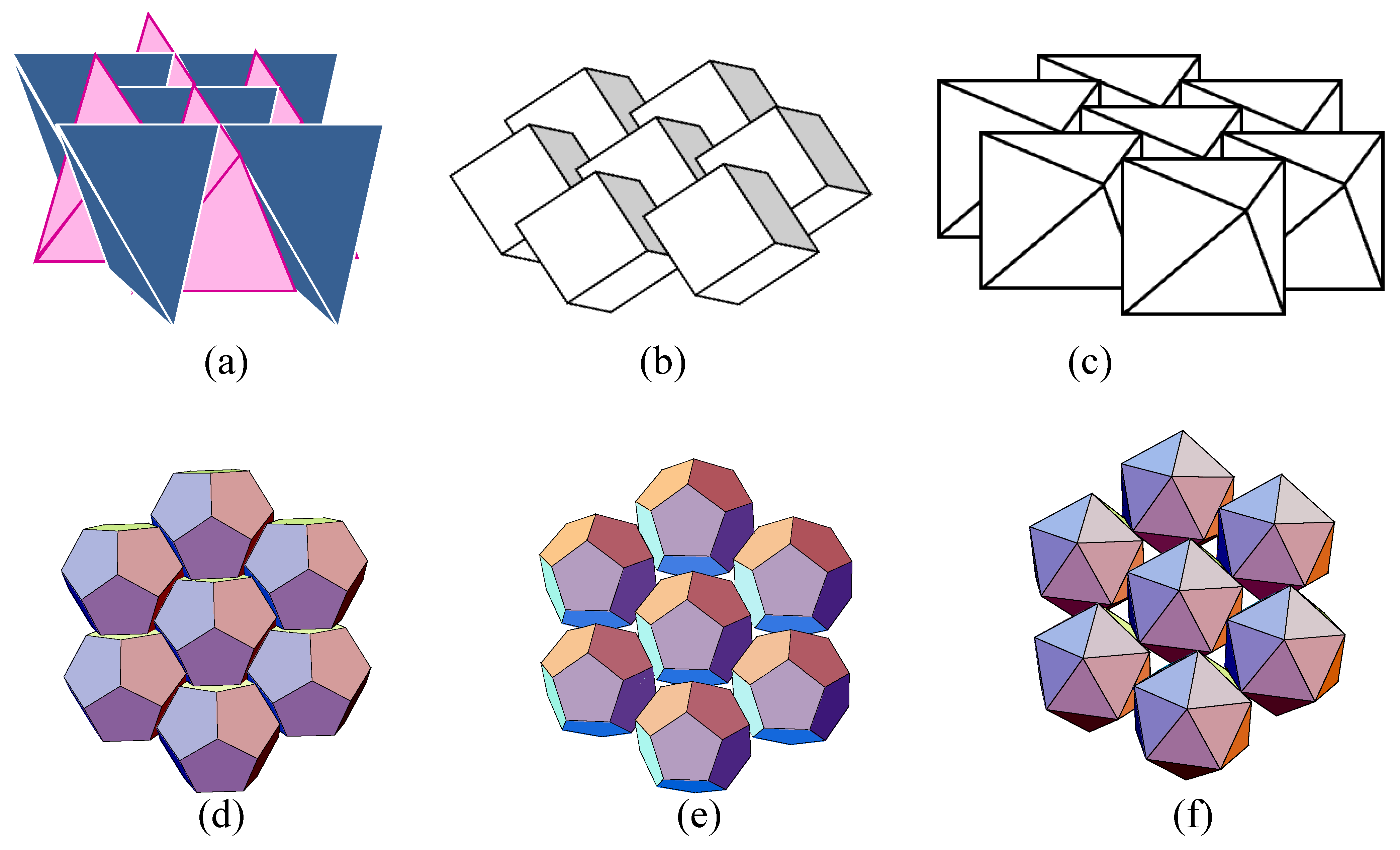
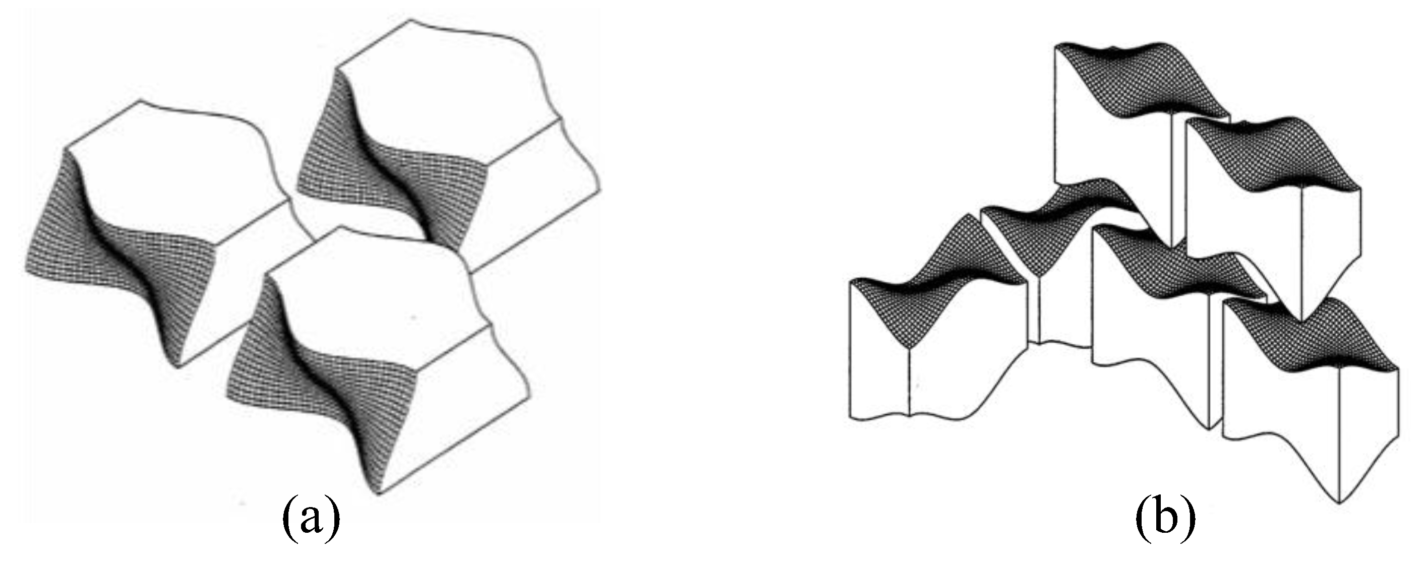
2. Motion of Blocks in Topological Interlocking Beams/Plates and Simplified Modeling

In topological interlocking the blocks are not glued to each other and are free to move apart from each other. The resistance to the movement of the blocks is only provided by the stiffness of the peripheral constraint, which is considerably lower than the stiffness of the blocks themselves. This makes it possible to neglect the deformation of the block material. The absence of block binding also gives another mechanical feature of TI assemblies: each block has rotational degrees of freedom. Furthermore, since the blocks are far from being spherical, the relative rotation of neighboring blocks creates forces that push them apart, the phenomenon called elbowing [52], which produces additional deformation of the TI plate. This movement is resisted by the elasticity of the peripheral constraint.
In order to understand the effect of rotational degrees of freedom and elbowing, consider a 2D model of a cross-section of a TI plate in a co-ordinate frame (x, y); see the schematics in Figure 5. (This is essentially a toy model presented to investigate the main features of the mechanics of the deformation of interlocking structures. It extends the simplification proposed in [22].) Assume each block to be infinitely rigid. Each block can have positive relative displacement, u x > 0 , and rotation, ω z (the z-axis being directed from the reader), with zero vertical relative displacement, u y = 0 , ensured by interlocking. (This does not exclude macroscopic vertical deflection, that is u y 0 allowed by finite stiffness of the peripheral constraint.) Given the in-plane (axial) compression applied by the peripheral constraint, the relative displacement, u x > 0 , can only be produced by relative block rotation (elbowing). The relative rotation results in corner interactions of the neighboring blocks. Figure 7 shows a fragment of a topological interlocking beam with equal symmetrical blocks, Figure 7a, or with alternating blocks, Figure 7b, of shapes of two types. (We only consider curved contact surfaces, the ones that make topological interlocking beams possible). It is evident that the relative displacement and rotation under deflection-produced loading are controlled by the action of corners as long as the rotation is sufficient to open the contacts. The corners of these blocks coincide with the corners of simple rectangular blocks (broken lines in Figure 7a,b). Therefore, it is sufficient to model the blocks in a cross-section of interlocking plates by rectangular blocks, with restricted relative vertical displacements representing the effect of topological interlocking; this is expressed by the condition u y = 0 . We also note that if F x is the force (e.g., the constraining force), the moments created by it with respect to the block centroid are the same in all three cases shown in Figure 7.
We now use a beam-like assembly of rectangular blocks, Figure 7c, with relative vertical block displacement, u y = 0 , as a model of the TI beam. The following section uses this model to derive the point nature of beam deflection.

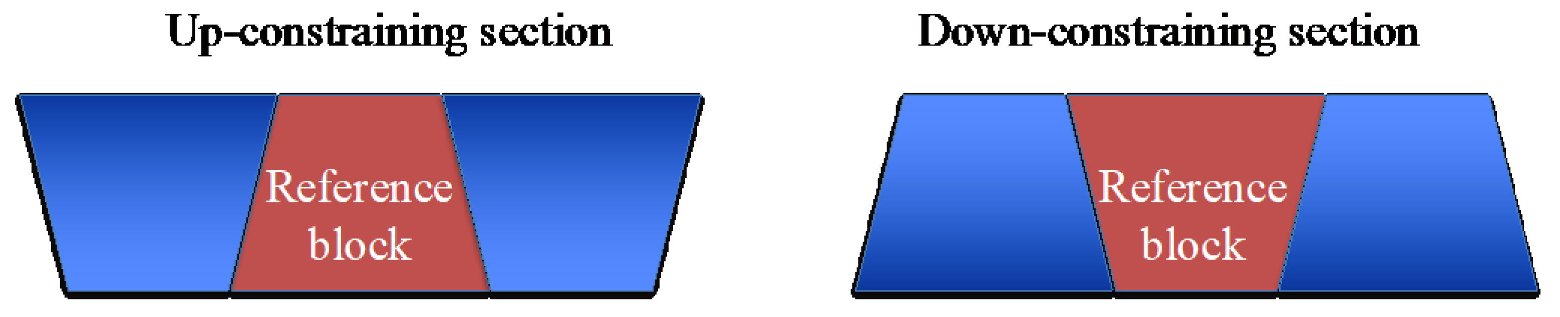
3. Rectangular Block Model of Topological Interlocking Beams

In line with the reasoning of the previous section, we consider a 2D model of the deflection of a TI beam as a beam consisting of n rectangular blocks of length a; its thickness is 2b. The beam length is 2 l = n a , Figure 8a. The beam is loaded by point force Q. The role of the peripheral constraint is played by an internal post-tensioning cable of stiffness k loaded by initial force F 0 (post-tensioning here refers to applying tension to the cables after the blocks are assembled).
Since topological interlocking does not resist tension, the behavior of a TI beam is controlled by a post-tensioning cable or external constraint. Appendix A shows that a post-tensioning cable and an external constraint frame affect the bending in a similar way. Macroscopically, the cable behaves as a string (Figure 8b). (Obviously, this deflection shape produces the smallest cable length increase, resulting in the minimum elastic energy of the cable.) The tension in the string is produced by elbowing [52], which produces an additional deformation that is an increase in the distance between the block centers due to their relative rotation.
We name the deflection of this geometry point deflection in order to distinguish it from classical beam deflection. We use Figure 8b as a (macroscale) continuum model of the point deflection of the fragmented beams shown in Figure 8c,d. The discrete (microscopic) interpretations of the fragmented beam deflection will have the shapes shown in Figure 8c,d for odd and even numbers of blocks, respectively. Obviously, in the macroscopic model the length, a, of a block is not distinguishable. Subsequently, Figure 8 presents a mechanism of beam deflection localization [49].
Following this logic, one can also construct the fragmented beam deflection under a couple of point loads of equal, Figure 9a, or different, Figure 9b, magnitudes.

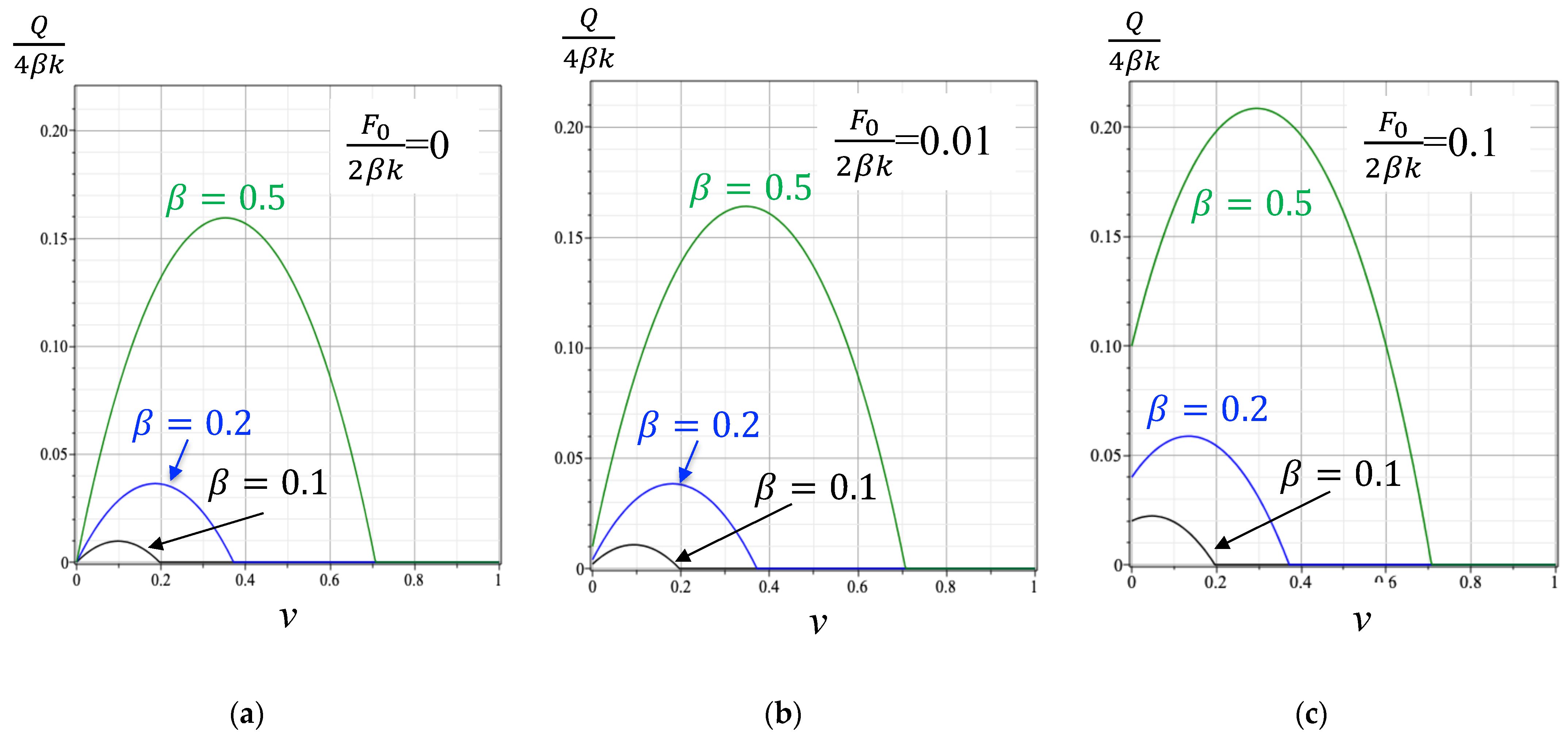
4. Apparent Negative Stiffness and Post-Peak Softening

We can now derive the force–deflection relationship. We start with a configuration shown in Figure 8d and consider the balance of moments created by the applied point force and the constraint force, Figure 10. We also introduce the following dimensionless variables:
v = u y l ,       β = b l
Consider the right part of the beam. Given that sin θ 2 = v , the moment created by the reaction force, Q/2, about point O is as follows:
M Q = Q 2 1 v 2 + 2 β v l ,         v < 1
We assume the constraining force linearly depending on the length increase caused by deflection:
F = F 0 + 2 β k v
Here, F 0 is the initial constraining force applied by either a cable (post-tensioning) or peripheral constraint frame; k is the effective stiffness of the constraint. Subsequently, the moment created by the constraining force, F, about point O is as follows:
M Q = F 0 + 2 β k v 2 β 1 v 2 v l ,       v < 1
Equating these moments, one obtains the following force–deflection relationship:
Q 4 β k = F 0 2 β k + v 2 β 1 v 2 v 1 v 2 + 2 β v ,       v < 1
Figure 11 shows the normalized force–deflection curves for different values of the normalized initial force, F 0 2 β k , and beam half-thickness, β . They start with F 0 = 0 , which corresponds to negligible pre-tension.
It is seen that the force–deflection curves show stages of considerable post-peak softening, that is, after the peak value the force–deflection relationship exhibits apparent negative stiffness. The peaks are reached at a critical deflection:
v c r = 2 β 1 + 4 β 2
The critical deflection is only controlled by the block geometry (the block aspect ratio in the case considered).
The beam deflection is stable when v < v c r and unstable (requires indentation with displacement control) when v > v c r . This critical deflection is an increasing function of the beam normalized thickness, b l , and is independent of the initial constraining force.
Thus, the relative rotations of neighboring blocks constitute a mechanism of negative stiffness, observed in [46,47]. (We note that the total energy of the system TI beam/plate plus the peripheral constraint is positive-definite.) It is also seen that the beam thickness β = b l has the strongest effect on the force–deflection curves, while the effect of constraining force F 0 2 β k is minor.
The following section will consider a simplified model of oscillations of TI beams with point deflection damped by air squeezing accounting for the discontinuous nature of the damping.

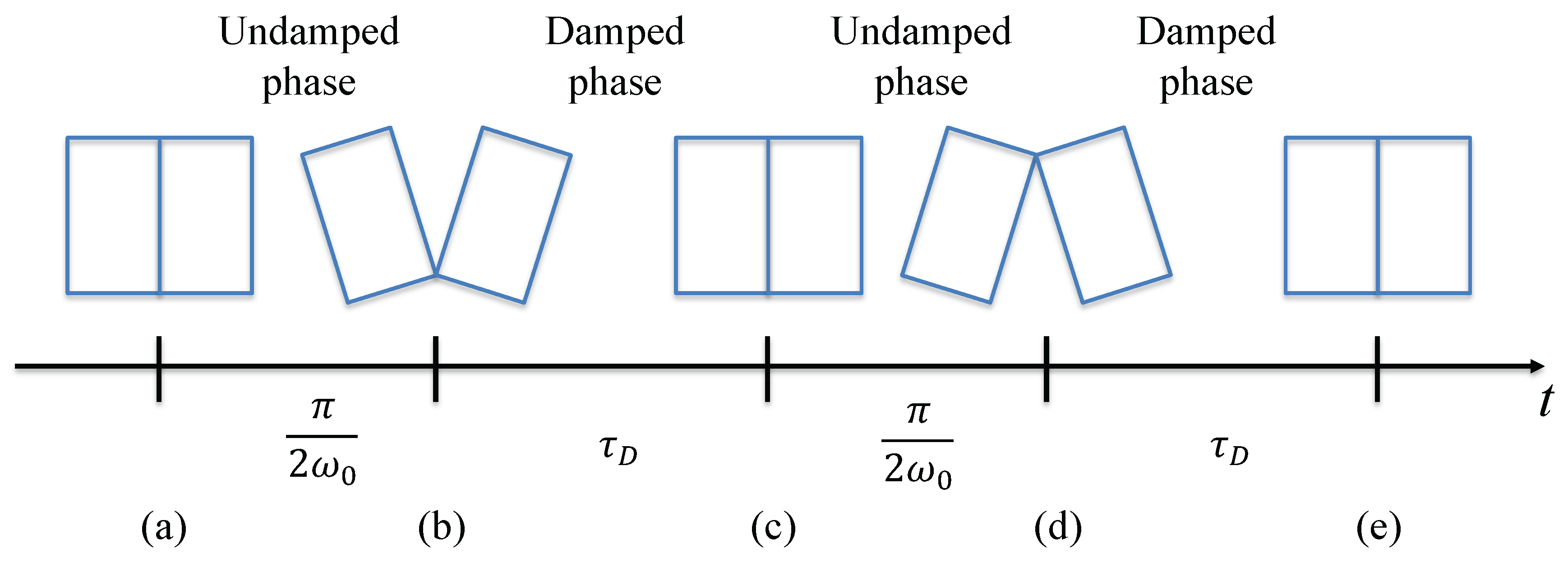
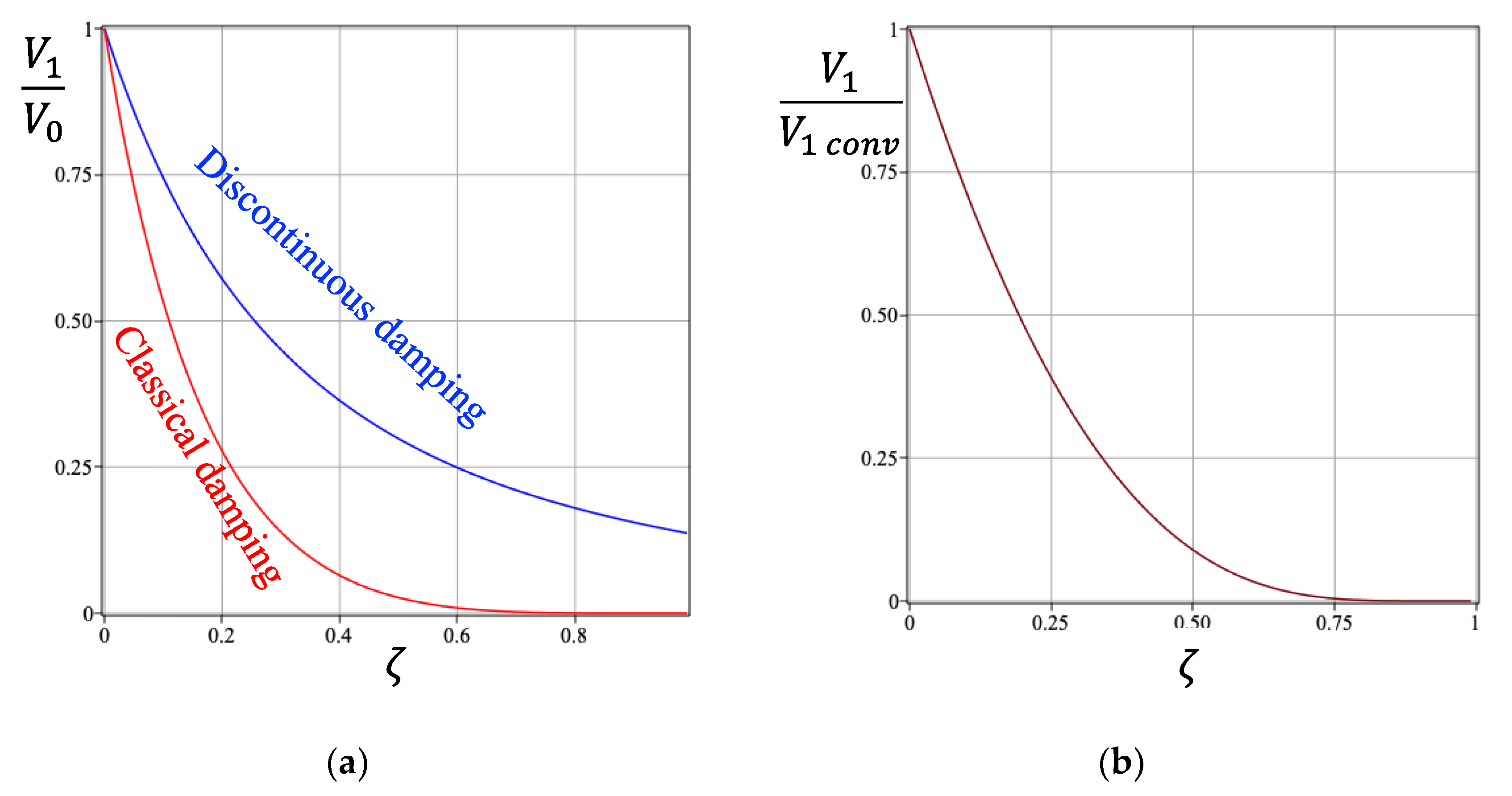
5. Oscillations of TI Beams with Discontinuous Linear Damping

Discontinuous damping is understood here as damping only working during a part of the oscillation period. Figure 12 illustrates the timeline of emerging discontinuities of damping produced by energy absorption due to air squeezing between the contacting surfaces of the neighboring blocks. It is seen that the oscillating cycle consists of two undamped–damped phases (Figure 12b–e). Therefore, the sequence of undamped–damped phases is antisymmetric, leading to equality in durations of the undamped and damped phases.
The damping phases involving air squeezing are discontinuous (passing from low damping pumping-in to high damping pumping-out) and non-linear [45]. Here, we concentrate on the analysis of the effect of the discontinuity of the damping. To this end, we consider a simplified model whereby the damping, when operational, is linearly characterized by damping ratio ζ . We assume that the oscillations start with an impulse applied at time t = 0 without the presence of external force. Then, the equations of motion for discontinuous damping read as follows:
v ¨ + ω 0 2 v = 0   for   phases   ( b ) ,   ( c ) v ¨ + 2 ζ v ˙ + ω 0 2 v = 0   for   phases   ( d ) ,   ( e )
Here, v is the displacement associated with oscillations, and ω 0 is the angular natural frequency of non-damped oscillations.
The initial conditions read as follows:
v 0 = 0 ,       v ˙ 0 = V 0
For the first undamped stage, the solution of Equation (7) with initial conditions (8) is obvious:
v t = V 0 ω 0 sin ω 0 t
Subsequently, the maximum displacement v m a x = V 0 ω 0 is reached at t = π 2 ω 0 . After reaching the maximum displacement, phase (c) starts, which is the damping phase. For this phase, the solution reads as follows:
v t = V 0 ω 0 e ζ ω 0 τ cos ω D τ + ζ 1 ζ 2 sin ω D τ ,     τ = t π 2 ω 0
v ˙ t = V 0 e ζ ω 0 τ ζ 1 ζ 2 sin ω D τ
This trajectory lasts until the contact faces are closed (end of phase (c)), that is, until time τ D , such that v τ D = 0 . Using Equation (10), one obtains the following:
V 1 = V 0 exp 2 ζ sin 1 1 ζ 2 1 ζ 2 ω D τ D = sin 1 1 ζ 2 1 ζ 2
The velocity at the end of this phase is as follows:
V 1 2 = v ˙ τ D = V 0 e ζ ω 0 τ D
Now, due to the antisymmetry, the following phases will give the same result as Equation (13), but with the opposite sign. Therefore, at the end of the cycle, that is, at the beginning of the following cycle, the initial velocity is as follows:
V 1 = V 0 exp 2 ζ sin 1 1 ζ 2 1 ζ 2
It is seen that the discontinuous damping reduces the velocity by exp 2 ζ sin 1 1 ζ 2 1 ζ 2 , or the logarithmic decrement is δ = 2 ζ sin 1 1 ζ 2 1 ζ 2 .
Figure 13a compares this velocity reduction with the velocity reduction after one cycle of the conventional system with linear damping:
V 1   c o n v = V 0 e 2 π ζ 1 ζ 2
Obviously, the discontinuous damping is less effective than the conventional damping. The ratio of the discontinuous damping to the conventional damping is shown in Figure 13b. It is seen that the efficiency of the discontinuous damping drops with an increase in the damping ratio.
In order to determine the natural frequency of the oscillation of a TI beam with a single deflection point (Figure 10), we note that the increase in the beam length is l = u b / l . From here, assuming that the cable stiffness is k , one obtains the effective stiffness of the oscillator k O = M k b / l , where M is the mass of the beam. Subsequently, the natural frequency is as follows:
ω 0 2 = M k b l
where b is half of the block height. Subsequently, the square of the damping frequency is as follows:
ω D 2 = M k b l 1 ζ 2
The frequencies increase with block height and reduce with beam length.

6. Discussion

The point deflection observed under point loading is a consequence of the relative block rotations followed by the delamination of contacts of the neighboring blocks and elbowing. In the TI assemblies, the neighboring blocks do not resist local tension. Subsequently, there is no local bending stiffness. This makes the macroscopic bending of the TI beams resemble that of a string.
The second important point is that the constraint required for the structural integrity of TI assemblies is achieved either by an external frame or post-tensioning cables; both are characterized by a linear increase in the constraining force with the deflection-produced axial displacement, and hence behave similarly. Opposite to it in a model in which the constraining force is kept constant the point deflection will turn into the deflection of the central area, which enlarges with an increase in the deflection-generating force [53]. However, the deflection still has a tendency for localization in the central area and post-peak softening is also observed in the force–deflection diagram.
When a TI plate is loaded by a central force, the point deflection turns into a line-localized deflection with lines oriented according to the symmetries of the interlocking blocks. For instance, in the case of cubic blocks, the central plane of the TI plate has hexagonal symmetry [4]; subsequently, three localization lines inclined at 120 ° to each other are observed [47]. In the case of a TI plate assembled from tetrahedra, the localization lines are observed to be perpendicular to each other [51], in line with the square symmetry of the central plane of the TI assembly of tetrahedra [4].
When a TI beam is subjected to several point loads, the deflection will have inflection points equal to the number of the applied forces. Between these points the deflection is linear. If, however, the load is continuous, there shall be no inflection points. For instance, in the case of uniform load q x = q 0 (in the coordinate frame shown in Figure 8b) under the constraining force F 0 , the solution of loaded string, e.g., as in [54], gives a parabolic shape, u y x = q 0 2 F 0 l 2 x 2 .
Discontinuous damping is an intrinsic property of TI structures. The damping is produced by the transfer of oscillating energy to the kinetic energy of the air squeezed out due to the gap closure between the neighboring blocks. Thus, damping is achieved without additional dampers and therefore can be used for designing hybrid materials and materials with internal architecture, where sound absorption/attenuation is a design parameter. The discontinuous nature of the damping may impose additional numerical difficulty for modeling oscillations of interlocking structures, so special algorithms may need to be developed to deal with the discontinuity of this kind.

7. Conclusions

The main feature of topological interlocking (TI) assemblies is the absence of bonding between their elements (blocks), which allows relative block rotation and subsequent elbowing. It is the rotations and elbowing that lead to the principal difference between the behavior of interlocking structures and solids demonstrated by the phenomenon of point deflection and localization. This new concept sets up a framework for future experiments and the design of topological interlocking structures.
The proposed concept is based on the consideration that the relative rotations of non-cylindrical or non-spherical blocks lead to elbowing, that is, transferring rotation into in-plane displacement (parting) of the blocks. This has a profound effect on the out-of-plane deformation of TI beams and plates: elbowing increases load in the lateral constraint (e.g., increases tension in the post-tensioning cables). As a result, the bending resistance of the beam/plate is transferred from the conventional bending stiffness, which is zero in the TI assemblies, to the resistance effected by the lateral constraint. This allows the modeling bending of TI beams using the concept of a tensioned string, even if the constraint is external. When point forces are applied, the TI beam undergoes point deflection, whereby the bending is localized at the points of force application with linear deflection in-between.
Another prominent consequence of block rotations is the force–deflection relationship containing post-peak softening, which can be interpreted as a manifestation of apparent negative stiffness (total energy of the system TI beam/plate plus the peripheral constraint is positive-definite). The post-peak phase of beam deflection can also be modeled using the concept of tensioning string and elbowing. The post-peak softening phase reflects the unstable phase of the deformation process, which is an important feature of the behavior of TI structures.
Damping during the bending of TI beams is produced by the transfer of the energy of oscillations to the kinetic energy of the air squeezed out due to interface closing between neighboring blocks in the process of oscillations. Being less efficient than classical damping, air squeezing damping has significant advantages over classical external damping devices, as air squeezing damping is an integral part of TI structures and hence does not require the installation of additional dampers. This property can be used for designing hybrid materials and materials with internal architectures, where sound absorption/attenuation is a design parameter.
The proposed theoretical framework and the models are important for developing methods for controlling the deformation of TI structures and for designing flexible structures with intrinsic energy absorption.

Author Contributions

Conceptualization, A.V.D. and E.P.; methodology, E.P.; formal analysis, A.V.D.; writing—original draft preparation, A.V.D.; writing—review and editing, E.P. All authors have read and agreed to the published version of the manuscript.

Funding

This research received no external funding.

Institutional Review Board Statement

Not applicable.

Informed Consent Statement

Not applicable.

Data Availability Statement

The original contributions presented in this study are included in the article. Further inquiries can be directed to the corresponding author.

Conflicts of Interest

The authors declare no conflicts of interest.

Appendix A. Equivalence of Constraining by the Post-Tensioning Cable and by the Peripheral Constraint

Consider two neighboring blocks, which assume under load the relative rotation θ (Figure 7c). In the case of constraining by a pre-tensioning cable running through the block centers, the increase in the cable length is as follows:
l c = 2 b sin θ 2
Similarly, in the case of peripheral constraint, the increase in the cable length is as follows:
l c = 4 b   sin θ / 2
In the case of constraint by a pre-tensioning cable running through the block centers, the cable shape corresponding to the minimal length increase is the point deflection shown in Figure 8b. This ensures the minimum elastic energy of the cable.
In the case of peripheral constraint, the minimum elastic energy is reached by the minimum projection length on the x-axis. This corresponds to the minimum length of the envelope line touching the lower block corners. Since in both cases of constraint the length increases are directly proportional, the point deflection shapes will have to be the same.

References

  1. Dyskin, A.V.; Estrin, Y.; Kanel-Belov, A.J.; Pasternak, E. A new concept in design of materials and structures: Assemblies of interlocked tetrahedron-shaped elements. Scr. Mater. 2001, 44, 2689–2694. [Google Scholar] [CrossRef]
  2. Dyskin, A.V.; Estrin, Y.; Kanel-Belov, A.J.; Pasternak, E. Topological interlocking of platonic solids: A way to new materials and structures. Phil. Mag. Lett. 2003, 83, 197–203. [Google Scholar] [CrossRef]
  3. Dyskin, A.V.; Estrin, Y.; Kanel-Belov, A.J.; Pasternak, E. Interlocking properties of buckyballs. Phys. Lett. A 2003, 319, 373–378. [Google Scholar] [CrossRef]
  4. Kanel-Belov, A.J.; Dyskin, A.V.; Estrin, Y.; Pasternak, E.; Ivanov-Pogodaev, I.A. Interlocking of convex polyhedra: Towards a geometric theory of fragmented solids. Mosc. Math. J. 2010, 10, 337–342. [Google Scholar] [CrossRef]
  5. Dyskin, A.V.; Estrin, Y.; Kanel-Belov, A.Y.; Pasternak, E. Toughening by fragmentation—How topology helps. Adv. Eng. Mater. 2001, 3, 885–888. [Google Scholar] [CrossRef]
  6. Dyskin, A.V.; Estrin, Y.; Pasternak, E.; Khor, H.C.; Kanel-Belov, A.J. Fracture resistant structures based on topological interlocking with non-planar contacts. Adv. Eng. Mater. 2003, 5, 116–119. [Google Scholar] [CrossRef]
  7. Rezaee Javan, A.; Seifi, H.; Xu, S.; Xie, Y.M. Design of a new type of interlocking brick and evaluation of its dynamic performance. In Proceedings of the IASS Annual Symposium 2016: Spatial Structures in the 21 Century, Tokyo, Japan, 26–30 September 2016; Kawaguchi, K., Ohsaki, M., Takeuchi, T., Eds.; International Association for Shell and Spatial Structures (IASS): Tokyo, Japan, 2016; pp. 1–8. [Google Scholar]
  8. Oikonomopoulou, F.; Bristogianni, T.; Barou, L.; Jacobs, E.; Frigo, G.; Veer, F.A.; Nijsse, R. A novel, demountable structural glass system out of dry-assembly, interlocking cast glass components. In Challenging Glass 6, Proceedings of the Conference on Architectural and Structural Applications of Glass, Delft, The Netherlands, 17–18 May 2018; Louter, C., Bos, F., Belis, J., Eds.; Delft University of Technology: Delft, The Netherlands, 2018; Paper 6. [Google Scholar]
  9. Bejarano, A.; Hoffmann, C. A generalized framework for designing topological interlocking configurations. Int. J. Archit. Comput. 2019, 17, 53–73. [Google Scholar] [CrossRef]
  10. Wang, Z.; Song, P.; Pauly, M. Design and structural optimization of topological interlocking assemblies. ACM Trans. Graph. 2019, 38, 193. [Google Scholar] [CrossRef]
  11. Loing, V.; Baverel, O.; Caron, J.-F.; Mesnil, R. Free-form structures from topologically interlocking masonries. Autom. Constr. 2020, 113, 103117. [Google Scholar] [CrossRef]
  12. Piekarski, N. Floor slabs made from topologically interlocking prefabs of small size. Buildings 2020, 10, 76. [Google Scholar] [CrossRef]
  13. Kim, D.Y.; Siegmund, T. Mechanics and design of topologically interlocked irregular quadrilateral tessellations. Mater. Des. 2021, 212, 110155. [Google Scholar] [CrossRef]
  14. Lecci, F.; Mazzoli, C.; Bartolomei, C.; Gulli, R. Design of flat vaults with topological interlocking solids. Nexus Netw. J. 2021, 23, 607–627. [Google Scholar] [CrossRef]
  15. Koureas, I.; Pundir, M.; Feldfogel, S.; Kammer, D.S. On the failure of beam-like topologically interlocked structures. Intern. J. Solids Struct. 2022, 259, 112029. [Google Scholar] [CrossRef]
  16. Akpanya, R.; Goertzen, T.; Niemeyer, A.C. A group-theoretic approach for constructing spherical-interlocking assemblies. In Proceedings of the of the IASS Annual Symposium 2023: Integration of Design and Fabrication, Melbourne, Australia, 10–14 July 2023. [Google Scholar]
  17. Stüttgen, S.; Akpanya, R.; Beckmann, B.; Chudoba, R.; Robertz, D.; Niemeyer, A.C. Modular construction of topological interlocking blocks—An algebraic approach for resource-efficient carbon-reinforced concrete structures. Buildings 2023, 13, 2565. [Google Scholar] [CrossRef]
  18. Kim, D.Y.; Siegmund, T. Chirality in topologically interlocked material systems. Mech. Mater. 2024, 191, 104956. [Google Scholar] [CrossRef]
  19. Akleman, E.; Krishnamurthy, V.R.; Fu, C.-A.; Subramanian, S.G.; Ebert, M.; Eng, M.; Starrett, C.; Panchal, H. Generalized Abeille tiles: Topologically interlocked space-filling shapes generated based on fabric symmetries. Comput. Graph. 2020, 89, 156–166. [Google Scholar] [CrossRef]
  20. Hua, H. Porous interlocking assembly: Performance-based dry masonry construction with digital stereotomy. Archit. Intell. 2024, 3, 20. [Google Scholar] [CrossRef]
  21. Shilova, E.; Bencini, N. A framework for parametric structural design of topological interlocking flat vaults. In Proceedings of the IASS 2024 Symposium: Redefining the Art of Structural Design, Zurich, Switzerland, 26–30 August 2024; Block, P., Boller, G., DeWolf, C., Pauli, J., Kaufmann, W., Eds.; 2024. [Google Scholar]
  22. Laudage, S.; Guenther, E.; Siegmund, T. Design and analysis of a lightweight beam-type topologically interlocked material system. Structures 2023, 51, 1402–1413. [Google Scholar] [CrossRef]
  23. Koureas, I.; Pundir, M.; Feldfogel, S.; Kammer, D.S. Beam-like topologically interlocked structures with hierarchical interlocking. ASME J. Appl. Mech. 2023, 90, 081008. [Google Scholar] [CrossRef]
  24. Patton, F.D. Multiple modes of shear failure in rock. In Proceedings of the 1st Congress of the International Society for Rock Mechanics (ISRM), Lisbon, Portugal, 25 September–1 October 1966; pp. 509–513. [Google Scholar]
  25. Dyskin, A.V.; Estrin, Y.; Kanel-Belov, A.J.; Pasternak, E. A new principle in design of composite materials: Reinforcement by interlocked elements. Compos. Sci. Technol. 2003, 63, 483–491. [Google Scholar] [CrossRef]
  26. Autruffe, A.; Pelloux, F.; Brugger, C.; Duval, P.; Bréchet, Y.; Fivel, M. Indentation behaviour of interlocked structures made of ice: Influence of the friction coefficient. Adv. Eng. Mater. 2007, 9, 663–666. [Google Scholar] [CrossRef]
  27. Dyskin, A.V.; Caballero, A. Orthogonal crack approaching an interface. Eng. Fract. Mech. 2009, 76, 2476–2485. [Google Scholar] [CrossRef]
  28. Tessmann, O.; Becker, M. Extremely heavy and incredibly light: Performative assemblies in dynamic environments. In Proceedings of the 18th International Conference on Computer-Aided Architectural Design Research in Asia (CAADRIA 2013), Singapore, 15–18 May 2013; pp. 469–478. [Google Scholar]
  29. Weizmann, M.; Amir, O.; Grobman, Y.J. Topological interlocking in buildings: A case for the design and construction of floors. Autom. Constr. 2016, 72 Pt 1, 18–25. [Google Scholar] [CrossRef]
  30. Alothman, S.; Chavan, C. Topological interlocking systems for the construction of seismic-proof shell structures. In Proceedings of the IASS Symposium 2018: Creativity in Structural Design, Boston, MA, USA, 16–20 July 2018. [Google Scholar]
  31. Totoev, Y.; Al Harthy, A. Semi interlocking masonry as infill wall system for earthquake resistant buildings: A review. J. Eng. Res. (TJER) 2016, 13, 33–41. [Google Scholar] [CrossRef]
  32. Piirainen, V.Y.; Estrin, Y. Topological interlocking as a principle of engineering design in construction of marine and coastal structures. J. Min. Inst. 2017, 226, 480–486. [Google Scholar]
  33. Molotnikov, A.; Gerbrand, R.; Qi, Y.; Simon, G.P.; Estrin, Y. Design of responsive materials using topologically interlocked elements. Smart Mater. Struct. 2015, 24, 25034. [Google Scholar] [CrossRef]
  34. Estrin, Y.; Molotnikov, A.; Simon, G.P.; Kaloshkin, S.; Senatov, F.; Maksimkin, A. Flexible ceramics with self-stiffening capability. In Proceedings of the European Symposium on Intelligent Materials 2015, Kiel, Germany, 10–12 June 2015. [Google Scholar]
  35. Djumas, L.; Molotnikov, A.; Simon, G.P.; Estrin, Y. Enhanced mechanical performance of bio-inspired hybrid structures utilising topological interlocking geometry. Sci. Rep. 2016, 6, 26706. [Google Scholar] [CrossRef] [PubMed]
  36. Djumas, L.; Simon, G.P.; Estrin, Y.; Molotnikov, A. Deformation mechanics of non-planar topologically interlocked assemblies with structural hierarchy and varying geometry. Sci. Rep. 2017, 7, 11844. [Google Scholar] [CrossRef]
  37. Molotnikov, A.; Estrin, Y.; Dyskin, A.V.; Pasternak, E.; Kanel-Belov, A.J. Percolation mechanism of failure of a planar assembly of interlocked osteomorphic elements. Eng. Fract. Mech. 2007, 74, 1222–1232. [Google Scholar] [CrossRef]
  38. Thompson, J.M.T.; Bokaian, A.R.; Ghaffari, R. Subharmonic resonances and chaotic motions of a bilinear oscillator. IMA J. Appl. Math. 1983, 31, 207–234. [Google Scholar] [CrossRef]
  39. Dyskin, A.V.; Pasternak, E.; Pelinovsky, E. Periodic motions and resonances of impact oscillators. J. Sound Vib. 2012, 331, 2856–2873. [Google Scholar] [CrossRef]
  40. Khudyakov, M.; Dyskin, A.V.; Pasternak, E. Continuum model of wave propagation in fragmented media: Linear damping approximation. Nonlinear Process. Geophys. 2017, 24, 461–466. [Google Scholar] [CrossRef]
  41. Carlesso, M.; Molotnikov, A.; Krause, T.; Tushtev, K.; Kroll, S.; Rezwan, K.; Estrin, Y. Enhancement of sound absorption properties using topologically interlocked elements. Scripta Mater. 2012, 66, 483–486. [Google Scholar] [CrossRef]
  42. Ali, M.; Briet, R.; Chouw, N. Dynamic response of mortar-free interlocking structures. Constr. Build. Mater. 2013, 42, 168–189. [Google Scholar] [CrossRef]
  43. Schapira, Y.; Chernin, L.; Shufrin, I. Blast energy absorption in topological interlocking elastic columns. Mech. Adv. Mater. Struct. 2024, 31, 935–947. [Google Scholar] [CrossRef]
  44. Feng, Y.; Siegmund, T.; Habtour, E.; Riddick, J. Impact mechanics of topologically interlocked material assemblies. Intl. J. Impact Eng. 2015, 75, 140–149. [Google Scholar] [CrossRef]
  45. Pantaleone, J. How the air slows a closing book. Am. J. Phys. 2024, 92, 7–13. [Google Scholar] [CrossRef]
  46. Estrin, Y.; Dyskin, A.V.; Pasternak, E.; Schaare, S.; Stanchits, S.; Kanel-Belov, A.J. Negative stiffness of a layer with topologically interlocked elements. Scr. Mater. 2004, 50, 291–294. [Google Scholar] [CrossRef]
  47. Schaare, S.; Dyskin, A.V.; Estrin, Y.; Arndt, S.; Pasternak, E.; Kanel-Belov, A.J. Point loading of assemblies of interlocked cube-shaped elements. Int. J. Eng. Sci. 2008, 46, 1228–1238. [Google Scholar] [CrossRef]
  48. Mather, A.; Cipra, R.; Siegmund, T. Structural integrity during remanufacture of a topologically interlocked material. Intern. J. Struct. Integr. 2012, 3, 61–78. [Google Scholar] [CrossRef]
  49. Safiee, N.A.; Jaafar, M.S.; Alwathaf, A.H.; Noorzaei, J.; Abdulkadir, M.R. Structural behavior of mortarless interlocking load bearing hollow block wall panel under out-of-plane loading. Adv. Struct. Eng. 2011, 14, 1184–1196. [Google Scholar] [CrossRef]
  50. Krause, T.; Molotnikov, A.; Carlesso, M.; Rente, J.; Rezwan, K.; Estrin, Y.; Koch, D. Mechanical properties of topologically interlocked structures with elements produced by freeze gelation of ceramic slurries. Adv. Eng. Mater. 2012, 14, 335–341. [Google Scholar] [CrossRef]
  51. Khandelwal, S.; Siegmund, T.; Cipra, R.J.; Bolton, J.S. Scaling of the elastic behavior of two-dimensional topologically interlocked materials under transverse loading. J. Appl. Mech. 2014, 81, 031011. [Google Scholar] [CrossRef]
  52. Pasternak, E.; Dyskin, A.V.; Estrin, Y. Deformations in transform faults with rotating crustal blocks. Pure Appl. Geophys. 2006, 163, 2011–2030. [Google Scholar] [CrossRef]
  53. Odessa, I.; Shufrin, I. Nonlinear mechanics of fragmented beams. Eur. J. Mech. A/Solids 2022, 93, 104488. [Google Scholar] [CrossRef]
  54. Landau, L.D.; Lifshitz, E.M. Theory of Elasticity; Pergamon: Oxford, UK, 1959. [Google Scholar]
Figure 1. TI assemblies of (a) tetrahedra; (b) cubes; (c) octahedra; (d) dodecahedra, packing 1; (e) dodecahedra, packing 2; and (f) octahedra; the figures are drawn following [1,2,3,4,5].
Applsci 15 06496 g001
Figure 2. TI assemblies of osteomorphic blocks [6]: (a) planar assembly; (b) corner assembly.
Applsci 15 06496 g002
Figure 3. Two sections of TI assemblies: in the up-constraining section the reference block is prevented from moving up by its neighbors; in the down-constraining section the reference block is prevented from moving down (see also [23]).
Applsci 15 06496 g003
Figure 4. Crack growing towards an interface. Singularity of tensile stress, σ x , opens the interface, which prevents the crack from further growth (see [27] for details).
Applsci 15 06496 g004
Figure 5. Schematics of a cross-section of a TI beam.
Applsci 15 06496 g005
Figure 6. Illustration of localization lines developing in TI cubic assembly under indentation (observed in experiments and numerical modeling [50,51]): (a) central section of the TI assembly of cubes; and (b) generator cube with a hexagonal central section shown.
Applsci 15 06496 g006
Figure 7. Relative horizontal displacement and rotation, θ = ω z , of topological interlocking blocks in the process of deflection initiated by the interaction of the block corners (elbowing): (a) interaction of equal symmetrical blocks; (b) interaction of blocks of alternating shapes; and (c) equivalent rectangular blocks (in (a,b) these blocks are shown by broken lines).
Applsci 15 06496 g007
Figure 8. Fragmented beam model; the broken lines indicate the holes in the blocks for the post-tensioning cable (see Appendix A for the equivalence between the post-tensioning cable and an external constraint frame): (a) fragmented beam with n rectangular blocks of width a and height 2b as a model of a TI beam under point force Q; (b) point deflection of the post-tensioning cable; this configuration will be used as a representation of a macroscale continuum model of the bending of a fragmented beam; and (c,d) discrete (microscale) interpretations of the continuum model of the point deflection of a fragmented beam.
Applsci 15 06496 g008
Figure 9. Fragmented beam under two point loads: (a) equal point loads; (b) different point loads.
Applsci 15 06496 g009
Figure 10. Deflection, u y , of a fragmented beam under point load, Q, applied at the center.
Applsci 15 06496 g010
Figure 11. Normalized force–deflection curves for beam half-thicknesses b l = 0.1 ,   0.2 ,   0.5 and different magnitudes of the normalized initial force: (a) F 0 2 β k = 0 ; (b) F 0 2 β k = 0.01 ; and (c) F 0 2 β k = 0.1 .
Applsci 15 06496 g011
Figure 12. Illustration of air squeezing damping discontinuity during an oscillation period: (a) the period starts with neighboring blocks in close contact; (b) the first oscillation phase consists of opening the contact to its maximum, during which the air is pumped in (the damping associated with friction between the air and the block surfaces is neglected). This is a conventional linear phase; its duration is a quarter of undamped period π 2 ω 0 , where ω 0 is the angular natural frequency of non-damped oscillations. Phase (c) corresponds to closing the contact and squeezing the air out. This phase lasts for time τ D and ends up with the closed contact. (d) is another opening phase without damping. It essentially repeats phase (b) but with a negative sign. Phase (e) corresponds to closing the contact and squeezing the air out, similarly to phase (c), but with the opposite sign.
Applsci 15 06496 g012
Figure 13. Comparison of discontinuous damping with classical damping: (a) the reduction in the velocity after one cycle for discontinuous damping and classical damping; (b) the ratio of discontinuous to classical damping.
Applsci 15 06496 g013
Disclaimer/Publisher’s Note: The statements, opinions and data contained in all publications are solely those of the individual author(s) and contributor(s) and not of MDPI and/or the editor(s). MDPI and/or the editor(s) disclaim responsibility for any injury to people or property resulting from any ideas, methods, instructions or products referred to in the content.

