Article

Investigation of In Situ and Ex Situ Passivation of Pyrophoric Uranium–Niobium Alloy Powder

by
Evan M. Clarke
,
Hunter B. Henderson
,
Eric S. Elton
,
Tian T. Li
,
Logan D. Winston
,
Isabel R. Crystal
,
Olivia G. Long
,
Sharee L. Harris
,
Ryan L. Stillwell
,
Jason R. Jeffries
,
Joshua D. Kuntz
and
Kevin Huang
*
Lawrence Livermore National Laboratory, 7000 East Avenue, Livermore, CA 94550, USA
*
Author to whom correspondence should be addressed.
Appl. Sci. 2025, 15(12), 6431; https://doi.org/10.3390/app15126431 (registering DOI)
Submission received: 10 April 2025 / Revised: 3 June 2025 / Accepted: 5 June 2025 / Published: 7 June 2025

Abstract

:
This work evaluates the effectiveness of in situ and ex situ passivation methods for mitigating the pyrophoricity of uranium–6 wt.% niobium spherical powders produced via the hydride–dehydride process coupled with plasma spheroidization. Oxide layer thickness was characterized using STEM/EDX, and pyrophoricity was assessed by a UN-recommended test method, which involves directly dropping the powders in the air. In situ passivation, performed by introducing flowing oxygen during spheroidization, produced oxide layers ranging from tens to hundreds of nanometers but resulted in inconsistent pyrophoricity mitigation at lower oxygen flow rates. Ex situ passivation, achieved by slow oxygen exposure over several months, formed uniform oxide layers of approximately 20 nm and consistently mitigated pyrophoricity. Despite requiring higher bulk oxygen content, in situ passivation enables faster processing and control of oxygen, while ex situ passivation achieves superior oxide uniformity with lower oxygen incorporation. These findings highlight the trade-offs between passivation methods and provide a foundation for improving the safety and scalability of reactive metal powder production.

1. Introduction

Metal powder feedstocks are increasingly utilized in advanced material research, including dispersion-based nuclear fuels [1,2,3], additive manufacturing [4], novel catalysts [5,6], and biomedical implants [7]. Despite their potential, their widespread industrial adoption is hindered by significant safety concerns. A review of industrial accidents between 1980 and 2005 identified metal powders as the leading cause of dust fire and explosion incidents in the United States [8]. The high surface area-to-mass ratio of metal powders, compared to bulk metals, significantly increases their reactivity, making them prone to ignition. Pyrophoric materials (those capable of spontaneous ignition in air at or below 54.4 °C without an external ignition source, even in small quantities [9]) exhibit an extremely rapid and exothermic reaction with oxygen, directly leading to autoignition. Though the critical size to cause pyrophoricity depends on the specific material reactivity, even metals typically considered non-combustible, such as iron, can be pyrophoric when prepared as nanoparticles [10,11]. Uranium-based powders are highly pyrophoric and have been the subject of extensive investigations [12,13,14].
To mitigate the fire hazards associated with metal powders, common strategies include minimizing powder accumulation, eliminating or isolating ignition sources, and conducting operations under inert gas atmospheres [15]. However, these approaches have limitations. Administrative controls, such as minimizing powder accumulation and isolating ignition sources, are vulnerable to failure due to improper implementation. Additionally, operating under inert gas atmospheres is often economically or technically infeasible. Therefore, reducing the intrinsic reactivity of metal powders is critical to improving their safety and enabling their broader use in advanced applications.
Several techniques exist to reduce the reactivity of bulk metals to oxygen, such as chemical coatings and anodization. However, these methods are not always applicable to powders. Passivation is a well-known technique to make powders safer to handle [16,17] through the deliberate formation of a thin protective oxide layer on the surface of a metal, which slows or prevents further reaction with oxygen, reducing the risk of spontaneous combustion [18,19]. The effectiveness of passivation is dependent on how the metal oxidizes and the structure and properties of the oxide layer. For example, aluminum forms a tightly adhering oxide layer that effectively prevents further oxidation [20], whereas iron forms a loosely adhering oxide in humid air, which can even accelerate further oxidation [21,22].
For metals that do not naturally form protective oxide layers, alloying with specific elements can substantially improve their corrosion resistance. Uranium metal is known to readily form uranium oxide in air as a loosely adhered black powder [23]. However, uranium alloyed with six-percent niobium by weight (U-6Nb) in its α″ phase is known for its oxygen corrosion resistance [24,25,26]. The α″ phase is a metastable martensitic structure characterized by uniform niobium supersaturation, which is achieved by rapidly quenching the alloy from the high-temperature γ-phase [27]. In our previous work [28], we demonstrated an alternative route to produce 20–75 µm spherical U-6Nb powders via the hydride–dehydride (HDH) process followed by plasma spheroidization; however, the powders produced were found to be pyrophoric. This can be attributed to two factors. First, the metal powders produced were found not to be in the α″ phase but in a combination of distorted α and γ phases. Second, the HDH-prepared powders were found to have thin oxide layers (as thin as 5 nm) when compared to powders synthesized via other methods, which can have oxide layers over 50 nm thick [2,29,30]. Passivation by increasing the oxide layer thickness is an attractive method to mitigate pyrophoricity.
In this study, two passivation methods were applied to U-6Nb powders processed via the HDH-plasma spheroidization technique. The first method, in situ passivation, introduced a controlled amount of oxygen during the spheroidization process, allowing oxide formation to occur at elevated temperatures as the powder melts and resolidifies in the plasma chamber. The second method, ex situ passivation, was performed by exposing the already spheroidized powder to oxygen at ambient temperature over an extended period. Each method was evaluated based on the impact on material reactivity, as determined by pyrophoricity testing, as well as the uniformity and thickness of the oxide layers, as assessed by microscopy.

2. Materials and Methods

2.1. Powder Production

Due to the elevated pyrophoricity of the HDH-prepared U-6Nb powder and its hydride form (Video S1i,j), all synthesis, handling, and sample preparation of U-6Nb powder were conducted in a Vacuum Atmospheres OMNI-Lab 4-port glovebox (Vacuum Atmospheres Company, Hawthorne, CA, USA) under an argon atmosphere with less than 1 ppm O2 and less than 0.5 ppm H2O. The synthesis procedure followed the HDH-plasma spheroidization method previously reported [28].
In brief, bulk U-6Nb metal was reacted with hydrogen at 250 °C to form a metal-hydride powder in a custom Camco G-ATM-16 Hydrogen/Reducing Atmosphere Furnace (Concepts & Methods Co. Inc. (Camco Furnace), San Carlos, CA, USA) affixed to the side of the glovebox. The resulting metal hydride powder was milled to the target size in a Retsch PM100 planetary mill (Retsch GmbH, Haan, Germany) (175 rpm for 15 min) with 13 mm and 9 mm stainless steel milling media. The powder was then held at 500 °C under vacuum in the furnace to remove the hydrogen, yielding the U-6Nb powder. The powder was subsequently sieved to a target size range of 20–75 µm.
The HDH-prepared powder was transported to a Teksphero-15 plasma spheroidizer (Tekna Plasma Systems Inc., Sherbrooke QC, Canada) under argon, where it was fed into the plasma chamber using argon gas flowing at 5 standard liters per minute (SLPM). Ultra-high-purity (UHP) argon (40 SLPM) and UHP helium (25 SLPM) were introduced into the main chamber of the spheroidizer to form the plasma during spheroidization. The spheroidized powder was then collected, sieved again, and stored under argon.

2.2. Passivation

For ex situ passivation, no modifications were made to the spheroidization process. The unpassivated spherical powder was transferred to a Nalgene low-density polyethylene screw-top bottle in an argon atmosphere. The bottle was then removed from the glovebox, sealed around the cap with electrical tape, and placed in a stainless steel secondary container. The powder was left undisturbed in air for seven months, allowing oxygen to permeate the bottle and oxidize the powder at ambient temperature. After this period, the bottle was returned to the argon glovebox without further exposure to oxygen.
In situ passivation was performed during spheroidization by introducing a pre-mixed 2% O2/98% Ar gas into the plasma chamber. The passivation gas flow rate was set at a value between 0 and 10 SLPM, while the inert Ar/He gas input was held constant. The powder fell through the 0.67 m length of the chamber at a speed of approximately 4.6 m/s [28], passivating in less than 0.15 s. Due to the limited availability of materials, oxygen content (via SLPM) was the only parameter that varied during in situ passivation, as it was expected to have the greatest impact on the passivation. Unless noted otherwise, the in situ-passivated powders characterized were produced with a 5 SLPM passivation gas flow.

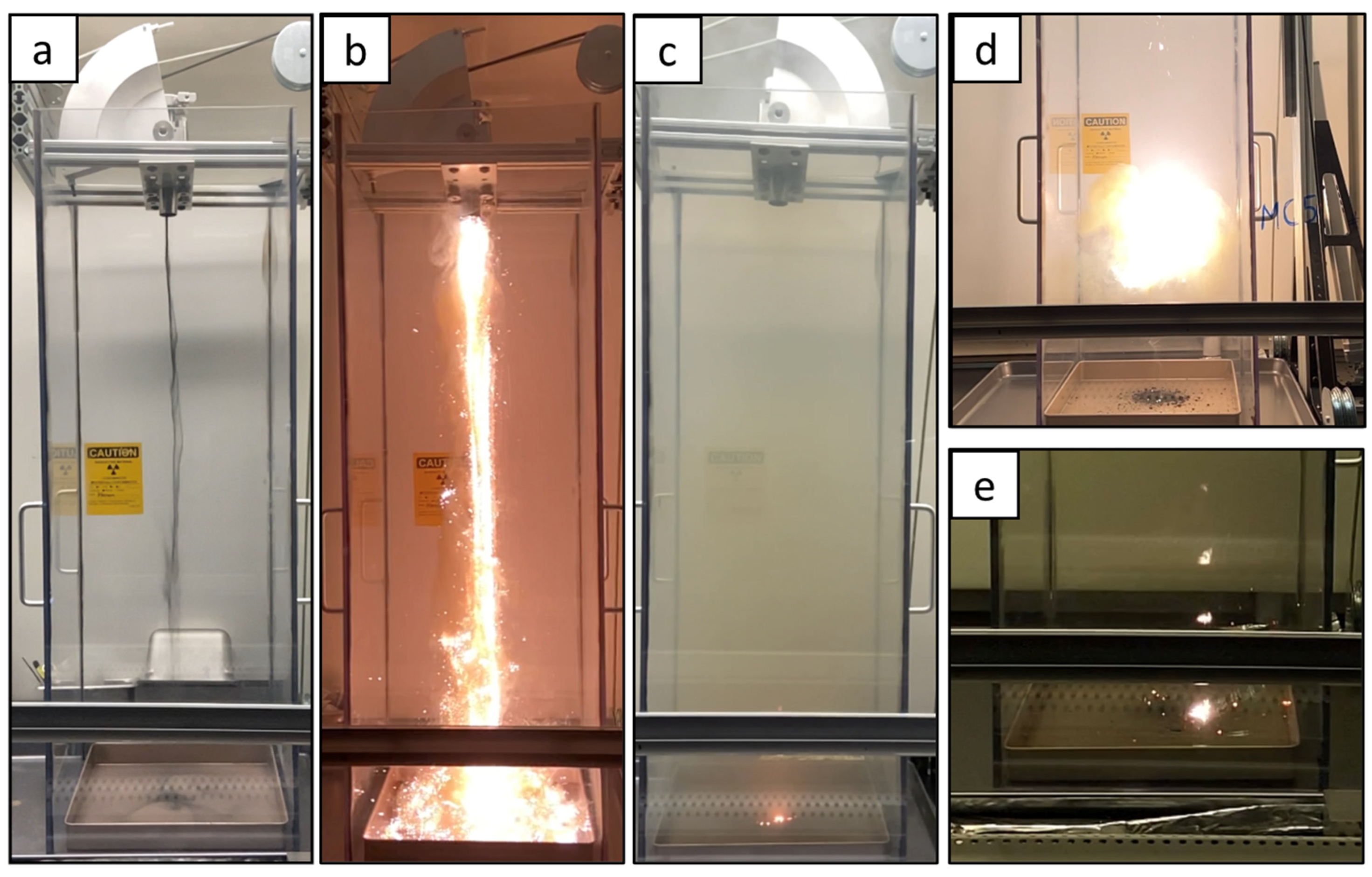
2.3. Pyrophoricity Testing (Sparkle Test)

Each powder sample was tested for pyrophoricity as described in the 7th revised edition of the Methods and Test Criteria portion of the UN Recommendations on the Transport of Dangerous Goods, Section 33.4.4, Test N.2, which is referred to herein for brevity as the “sparkle test” [31]. The sparkle test was conducted using custom-designed test apparatus (Figure S1). Powder aliquots were loaded inside an airtight KF16 stainless-steel ball valve container under argon, transferred to a fume hood, and remotely dropped from a height of one meter onto a steel catch pan. The apparatus was operated manually via cable-actuated pulleys from outside the fume hood, ensuring operator safety. All tests were performed inside a ventilated polycarbonate enclosure equipped with downstream HEPA filtration to capture any airborne particulates.
A 1–2 mL aliquot of powder was loaded into the test container and dropped from a height of one meter in air. The powder was observed for signs of pyrophoricity, such as sparks, fire, or glowing embers, over a five-minute period. The test was repeated six times with fresh, unreacted powder for each drop. A batch of powder was deemed non-pyrophoric if all six drops exhibited no signs of pyrophoricity. Failure was defined by the presence of sparks, fire, or glowing embers during the test. The signs of pyrophoricity were unambiguous, as shown in Figure 1 and Video S1.

2.4. Characterization

Optical microscopy of the powders was conducted using a Keyence VHX-6000 optical microscope. Powder X-ray diffractometry (PXRD) (Keyence Corporation, Osaka, Japan) was performed with the powders loaded into a Bruker A100B33 (Bruker AXS GmbH, Karlsruhe, Germany) airtight sample holder for air-sensitive samples and analyzed using a Bruker D8 Discover (Bruker AXS GmbH, Karlsruhe, Germany) with a CuKα source at 40 kV/40 mA. Rietveld refinements were conducted on the XRD data using GSAS-II software [32].
For transmission electron microscopy (TEM) measurements, ion milling techniques were employed to prepare the powder samples. A JEOL CP broad beam ion mill (JEOL Ltd., Akishima, Tokyo, Japan) was used for bulk cross-sectioning at 8 keV, and a FEI Nova600 NanoLab dual-beam (FEI Company, Hillsboro, OR, USA) Ga+ FIB was used to prepare site-specific lamella for TEM. Scanning transmission electron microscopy/energy-dispersive X-ray spectroscopy (STEM/EDX) was performed using a Thermo Fisher Titan (S)TEM (Thermo Fisher Scientific, Waltham, MA, USA).

3. Results and Discussion

3.1. Pyrophoricity Results

The initial syntheses of in situ-passivated U-6Nb spheres were conducted with passivation gas flow rates of between 0 and 10 SLPM, and the pyrophoricity of the resulting powder was evaluated using the sparkle test. The unpassivated powder (0 SLPM) and the powder passivated in situ with 2 SLPM of passivation gas failed the sparkle test, exhibiting bright sparks and fire. In contrast, powders synthesized with 1, 3, 4, 5, and 10 SLPM of passivation gas passed the test. Due to the observed pyrophoricity in the 1–3 SLPM range, 5 SLPM was selected as the default passivation gas flow rate for subsequent powder syntheses and characterization to ensure a safety margin. Among 22 subsequent batches synthesized with 5 SLPM of passivation gas, 17 passed the sparkle test, while five failed during at least one of the six drops.
For ex situ passivation, five synthesized batches of unpassivated U-6Nb spheres were allowed to sit in argon-filled plastic containers to allow for the slow diffusion of oxygen through the polyethylene walls and into the powder. An extended duration of seven months was selected to ensure complete passivation to minimize the risk of incomplete oxidation. After the exposure period, all five batches of ex situ-passivated powders successfully passed the sparkle test, confirming their non-pyrophoric nature.

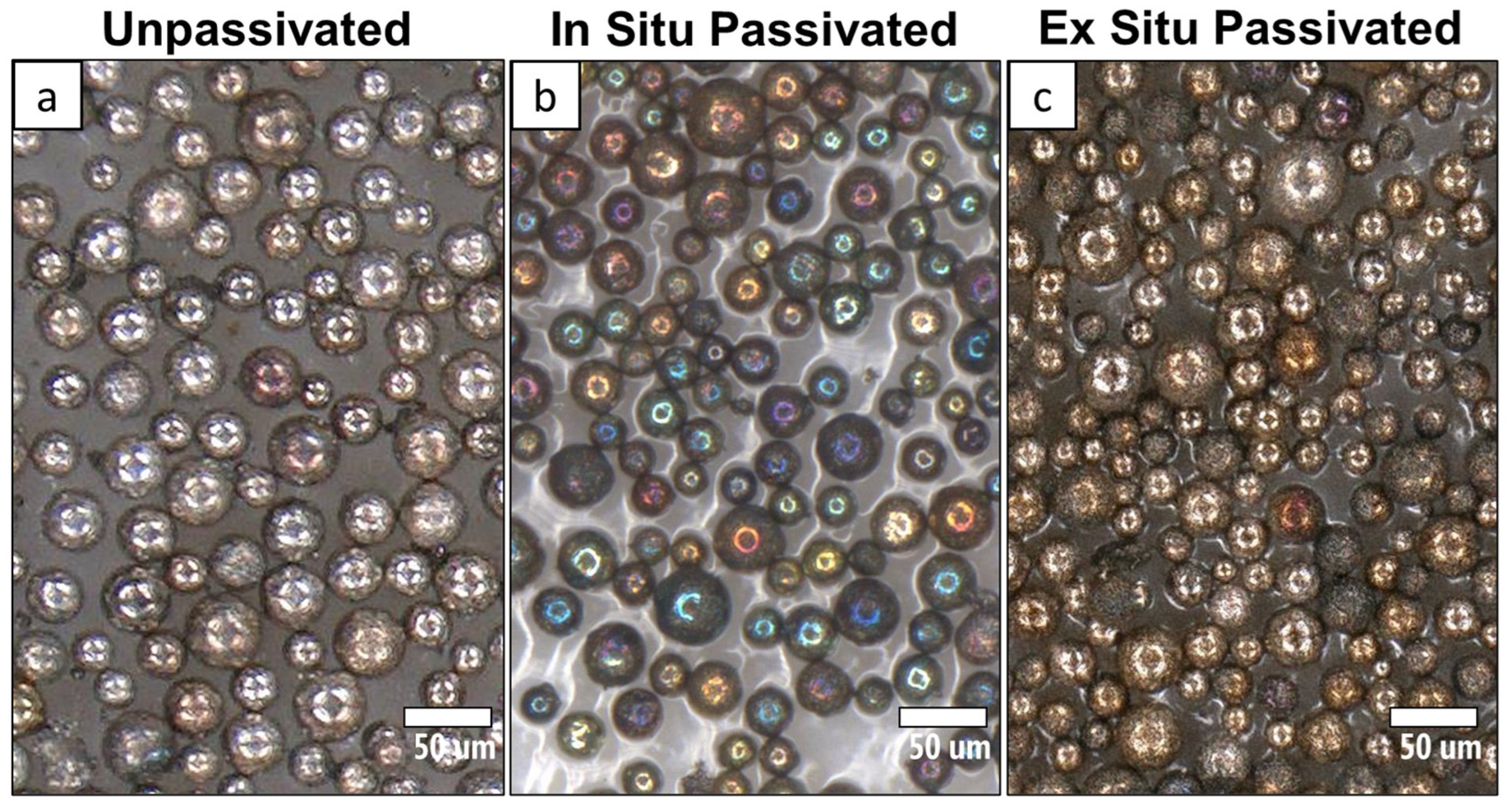
3.2. Optical Analysis and Color

The apparent color of a material can serve as a useful indicator of its oxide layer characteristics, with prior studies demonstrating the utility of the color analysis of uranium oxide powders through optical photography [33]. The thickness of the oxide layer influences color due to phase interference from light reflecting at the air–oxide and metal–oxide boundaries [34]. This phenomenon, commonly observed to cause color variations in metals such as anodized titanium [35], has been documented in both UO2 thin films on unalloyed uranium [36,37] and Nb2O5 thin films on niobium [38]. For U-6Nb, the oxide layer primarily consists of a continuous UO2 layer with an Nb2O5 layer between it and the bulk metal [24], suggesting that interference effects generate the observed colors. While the relationship between color and oxide thickness is well established for unalloyed uranium [37], it remains unexplored for U-6Nb. Nonetheless, the relative uniformity of the oxide layer thickness of U-6Nb can still be inferred from its consistent coloration.
Both in situ and ex situ passivation processes caused observable bulk color changes compared to the unpassivated powder. The unpassivated powder (Figure 2a) appears light silver-gray. With increasing passivation gas input during in situ passivation (Figure 2b), the powder becomes progressively darker, consistent with more UO2 formation at particle surfaces. Ex situ-passivated powder (Figure 2c) also appears distinctly darker than the unpassivated powder and visually similar to the powders passivated in situ at 1–3 SLPM.
However, apparent bulk powder color alone is insufficient to reliably predict pyrophoricity. For instance, while the ex situ-passivated powder consistently passes the sparkle test, powders passivated in situ at 1–3 SLPM occasionally fail. This discrepancy arises because combustion can be initiated by a small number of inadequately passivated particles (Video S1d), which is something that bulk characterization methods cannot effectively detect. Furthermore, it is important to note that non-pyrophoric particles do remain combustible and can still ignite if exposed to an ignition source, such as neighboring pyrophoric particles. Therefore, more localized analysis is required to resolve the individual particle passivation layer characteristics.
To further investigate the differences in passivation processes, individual spheres were analyzed by optical microscopy (Figure 3). Both unpassivated and ex situ-passivated powders show minimal sphere-to-sphere variation in color, indicating uniform oxide layer thickness. In contrast, the in situ-passivated powder (5 SLPM shown in Figure 3b) displays significant variations in color without any apparent correlation to particle size, ranging from light orange to blue-green to deep violet, suggesting substantial differences in oxide thickness among spheres.
While other factors, such as contamination by foreign chemical species or the presence of multiple oxide species, are known to cause color changes in metals, these alternatives can be excluded here. Contamination by outside chemical species was unlikely, given that identical feedstock materials and controlled inert atmosphere procedures were used for both methods. Although color differences can arise from differences in the ratio of the metal oxides, like in the case of Fe-Cr steel [39], differences in uranium-to-niobium oxide ratios are similarly improbable, since uranium oxide preferentially forms over niobium oxide due to its significantly lower Gibbs enthalpy of formation [24], which consistently results in a uranium-rich oxide surface.
Variation due to multiple uranium oxidation states (e.g., UO2 vs. U3O8) was also initially considered, as high temperatures during in situ passivation could favor the formation of higher-oxidation-state uranium oxides [40,41]. However, this was not observed in PXRD, with only UO2 detected (Figure S2), likely due to the limited oxygen content available during passivation. Therefore, oxide thickness variations rather than chemical or compositional discrepancies are the primary cause for the observed color range in the in situ-passivated powder.
For the color range between particles to result from different oxide thicknesses, there must be some variability in the local conditions within the plasma chamber. As evidenced by the visibly flickering intensity of the plasma (Video S2), there are temperature variations within the plasma. It might be expected that particles that reach higher temperatures will oxidize to a greater extent due to the temperature dependence of the oxidation rate of uranium regardless of the impact of niobium on oxide growth [42,43,44,45]. However, if temperature variation alone dictated the degree to which the powder particles oxidize, increasing the amount of passivation gas would not result in a higher oxygen content in the powder, which contradicts the experimental observations (Figure 2).
Any variation in oxygen concentration in the plasma chamber could also affect oxide layer growth. The passivation gas is introduced into the chamber below the plasma through 12 small holes around the circumference. As the powder falls through the center and the oxygen is introduced circumferentially, an oxygen concentration gradient likely appears, causing some spheres to passivate to a greater extent than others. Additionally, since the powder is not fed into the spheroidizer at a perfectly consistent rate, nonuniformity in the spatial arrangement of powder particles can also result in competition for oxygen between more closely packed particles, leading to lesser passivation than isolated particles with an abundance of surrounding oxygen. Unfortunately, due to material availability limitations, these parameters could not be independently investigated for their specific effects. Consequently, the complex gas mixing and competition for oxygen during spheroidization could result in a wide distribution of oxide thicknesses within a batch, evident in the rainbow coloration of in situ-passivated powder, in contrast to the uniform color of ex situ-passivated and unpassivated powder.

3.3. TEM and Oxide Thickness

To further investigate the oxide layers of the powders, spherical particles were sectioned with FIB milling to prepare a thin lamella suitable for TEM. Micrographs (Figure 4a,b,d,e) and elemental composition maps (Figure 4c,f) were obtained by STEM/EDX analysis, confirming the presence of the oxide layer on both the ex situ and in situ-passivated powder.
The oxide layer thickness on six ex situ-passivated particles was measured to range between 20 and 30 nm over a 3 µm length of the lamella, with a few localized spots as thin as 12 nm (Figure 4a–c). In contrast, the oxide layers on four in situ-passivated particles (5 SLPM of passivation gas) all exhibited localized regions with thicknesses in the hundreds of nanometers, interspersed with significantly thinner regions measuring as thin as 5 nm. Some particles had a maximum observed thickness of approximately 100 nm, while others had thicknesses over 200 nm, corroborating a wide disparity in oxide thickness from particle to particle.
The large range of oxide thicknesses on any given in situ-passivated sphere likely arose from rapid oxide nucleation and growth initiated at high temperatures, resulting in uneven surface coverage. After cooling, surfaces not already covered by thick oxide formed at high temperatures continued to be exposed to the passivating gas at lower temperatures until collection, which would explain why the regions in between the thicker areas have oxide thicknesses similar to or even thinner than the ex situ powder. The somewhat bimodal distribution of oxide thicknesses, with some areas heavily oxidized and others not, leaves parts of the particle surface highly reactive. This explains why in situ passivation with lower levels of passivating gas was not consistently effective, despite causing a bulk color change in the powder.
Moreover, because some particles received less overall passivation than others, there must be enough passivation gas to ensure the least passivated particles are sufficiently passivated. Because any small fraction of a sample that is reactive enough to undergo autoignition will cause the whole sample to ignite, there must be a relatively large excess of oxygen introduced during in situ passivation to ensure that even the thinnest regions have a sufficiently thick oxide layer.
In contrast, ex situ-passivated powders demonstrated more consistent and uniform oxide layer thickness, effectively mitigating pyrophoricity despite having thinner oxide layers. This indicates that the uniformity and continuity of oxide coverage are more critical to passivation effectiveness than simply achieving thicker average oxide layers. This uniformity ensures that no regions of the powder remain under-passivated. Consequently, assessments of powder passivation effectiveness should not rely solely on bulk oxide thickness measurements; rather, localized characterization of oxide uniformity is necessary.

4. Conclusions

In situ and ex situ passivation methods were evaluated for their effectiveness in mitigating the pyrophoricity of U-6Nb powders processed via the hydride–dehydride process and plasma spheroidization. Ex situ passivation produced uniform oxide layers (~20 nm) with consistent non-pyrophoric behavior, while in situ passivation resulted in variable oxide thicknesses (less than 10 nm to greater than 200 nm) and occasional pyrophoricity at lower oxygen flow rates. Despite requiring higher bulk oxygen content, in situ passivation enabled faster processing and safer handling immediately after production.
While both in situ and ex situ passivation can create non-pyrophoric U-6Nb powder, the trade-offs between the two methods emphasize the importance of application-specific considerations. Ex situ passivation ensures a uniform oxide layer with lower oxygen incorporation, while in situ passivation offers operational efficiency and precise control of bulk oxygen content. These findings can significantly enhance safety standards and material handling protocols for reactive metal powder production, supporting wider industrial and research applications.
Future efforts should focus on reducing the variability of in situ passivation by optimizing plasma chamber conditions to improve oxide layer uniformity. For ex situ passivation, the development of monitoring and control techniques for oxygen exposure and temperature control to decrease the time required to passivate and regulate oxide growth more precisely could enhance its reliability and scalability. Balancing safety, efficiency, and material performance remains critical for advancing the use of reactive metal powders in emerging applications.

Supplementary Materials

The following supporting information can be downloaded at https://www.mdpi.com/article/10.3390/app15126431/s1, Video S1: Sparkle test; Video S2: Plasma chamber; Figure S1: Sparkle test apparatus; Figure S2: Powder X-ray diffraction of in situ-passivated, ex situ-passivated, and unpassivated U-6Nb powder.

Author Contributions

Conceptualization, E.M.C., H.B.H., R.L.S., and K.H.; investigation, E.M.C., H.B.H., E.S.E., T.T.L., L.D.W., R.L.S., and K.H.; writing—original draft preparation, E.M.C.; writing—review and editing, E.M.C., H.B.H., E.S.E., I.R.C., O.G.L., S.L.H., and K.H.; visualization, E.M.C.; supervision, K.H., and J.R.J.; project administration, R.L.S., and K.H.; funding acquisition, J.D.K. All authors have read and agreed to the published version of the manuscript.

Funding

This research received no external funding.

Institutional Review Board Statement

Not applicable.

Informed Consent Statement

Not applicable.

Data Availability Statement

The original contributions presented in this study are included in the article/Supplementary Materials. Further inquiries can be directed to the corresponding author.

Acknowledgments

This manuscript has been authored by Lawrence Livermore National Security, LLC, under Contract No. DE-AC52-07NA27344 with the US. Department of Energy. The United States Government retains, and the publisher, by accepting the article for publication, acknowledges that the United States Government retains, a non-exclusive, paid-up, irrevocable, world-wide license to publish or reproduce the published form of this manuscript, or allow others to do so, for United States Government purposes.

Conflicts of Interest

The authors declare no conflicts of interest.

References

  1. Li, Y.; Zhang, J.; Jian, X.B.; Yan, F.; Ding, S.R.; Li, Y.M. Effects of Matrix Creep Properties on Effective Irradiation Swelling of U-10Mo/Zr Dispersion Nuclear Fuels. Front. Energy Res. 2022, 10, 851747. [Google Scholar] [CrossRef]
  2. McKeown, J.T.; Hsiung, L.L.; Ryu, H.J.; Park, J.M.; Turchi, P.E.A.; King, W.E. Rapidly solidified U–6wt%Nb powders for dispersion-type nuclear fuels. J. Nucl. Mater. 2014, 448, 72–79. [Google Scholar] [CrossRef]
  3. Susmikanti, M.; Sulistyo, J. Prediction of U-Mo Dispersion Nuclear Fuels with Al-Si Alloy Using Artificial Neural Network. Aip Conf. Proc. 2014, 1615, 175–181. [Google Scholar] [CrossRef]
  4. Singh, S.; Ramakrishna, S.; Singh, R. Material issues in additive manufacturing: A review. J. Manuf. Process. 2017, 25, 185–200. [Google Scholar] [CrossRef]
  5. He, J.L.; Hu, B.B.; Zhao, Y. Superaerophobic Electrode with Metal@Metal-Oxide Powder Catalyst for Oxygen Evolution Reaction. Adv. Funct. Mater. 2016, 26, 5998–6004. [Google Scholar] [CrossRef]
  6. Rayhan, U.; Do, J.H.; Arimura, T.; Yamato, T. Reduction of carbonyl compounds by Raney Ni-Al alloy and Al powder in the presence of noble metal catalysts in water. C. R. Chim. 2015, 18, 685–692. [Google Scholar] [CrossRef]
  7. Dewidar, M.M.; Yoon, H.C.; Lim, J.K. Mechanical properties of metals for biomedical applications using powder metallurgy process: A review. Met. Mater. Int. 2006, 12, 193–206. [Google Scholar] [CrossRef]
  8. Joseph, G.; Team, C.S.B.H.I. Combustible dusts: A serious industrial hazard. J. Hazard. Mater. 2007, 142, 589–591. [Google Scholar] [CrossRef] [PubMed]
  9. U.S. Department of Energy. Primer on Spontaneous Heating and Pyrophoricity; U.S. Department of Energy: Washington, DC, USA, 2020.
  10. Finzel, T.G. Pyrophoric iron. I. Preparation and properties. J. Am. Chem. Soc. 1930, 52, 142–149. [Google Scholar] [CrossRef]
  11. Sundaram, D.; Yang, V.; Yetter, R.A. Metal-based nanoenergetic materials: Synthesis, properties, and applications. Prog. Energy Combust. Sci. 2017, 61, 293–365. [Google Scholar] [CrossRef]
  12. Le Guyadec, F.; Génin, X.; Bayle, J.P.; Dugne, O.; Duhart-Barone, A.; Ablitzer, C. Pyrophoric behaviour of uranium hydride and uranium powders. J. Nucl. Mater. 2010, 396, 294–302. [Google Scholar] [CrossRef]
  13. Le Guyadec, F.; Rado, C.; Joffre, S.; Coullomb, S.; Chatillon, C.; Blanquet, E. Thermodynamic and experimental study of UC powders ignition. J. Nucl. Mater. 2009, 393, 333–342. [Google Scholar] [CrossRef]
  14. Berthinier, C.; Coullomb, S.; Rado, C.; Blanquet, E.; Boichot, R.; Chatillon, C. Experimental study of uranium carbide pyrophoricity. Powder Technol. 2011, 208, 312–317. [Google Scholar] [CrossRef]
  15. Reding, N.S.; Shiflett, M.B. Metal Dust Explosion Hazards: A Technical Review. Ind. Eng. Chem. Res. 2018, 57, 11473–11482. [Google Scholar] [CrossRef]
  16. Gromov, A.; Il’in, A.; Teipel, U.; Pautova, J. Passivation of Metal Nanopowders. In Metal Nanopowders; Wiley: Hoboken, NJ, USA, 2014; pp. 133–152. [Google Scholar]
  17. Ablitzer, C.; Le Guyadec, F.; Raynal, J.; Génin, X.; Duhart-Barone, A. Influence of superficial oxidation on the pyrophoric behaviour of uranium hydride and uranium powders in air. J. Nucl. Mater. 2013, 432, 135–145. [Google Scholar] [CrossRef]
  18. Chesnokova, R.V.; Bykov, B.G.; Bondareva, A.A.; Sychkova, L.A.; Alekseev, A.M.; Vasilevich, A.A.; Sazonova, I.S. Formation of Oxide Layer in Passivation of Pyrophoric Nickel Methanation Catalysts. Kinet Catal. 1984, 25, 168–173. [Google Scholar]
  19. Litrico, G.; Proulx, P.; Gouriet, J.B.; Rambaud, P. Controlled oxidation of aluminum nanoparticles. Adv. Powder Technol. 2015, 26, 1–7. [Google Scholar] [CrossRef]
  20. Jeurgens, L.P.H.; Sloof, W.G.; Tichelaar, F.D.; Mittemeijer, E.J. Growth kinetics and mechanisms of aluminum-oxide films formed by thermal oxidation of aluminum. J. Appl. Phys. 2002, 92, 1649–1656. [Google Scholar] [CrossRef]
  21. Pollitt, A.A. The Causes and Prevention of Corrosion; Van Nostrand: New York, NY, USA, 1924. [Google Scholar]
  22. Tamura, H. The role of rusts in corrosion and corrosion protection of iron and steel. Corros. Sci. 2008, 50, 1872–1883. [Google Scholar] [CrossRef]
  23. Wegman, R.F.; Van Twisk, J. 7—Other Metals. In Surface Preparation Techniques for Adhesive Bonding, 2nd ed.; Wegman, R.F., Van Twisk, J., Eds.; William Andrew Publishing: Norwich, NY, USA, 2013; pp. 105–114. [Google Scholar]
  24. Watkins, E.B.; Kruk, I.; Majewski, J.; Allred, D.D. Oxide structure of air-passivated U-6Nb alloy thin films. J. Nucl. Mater. 2020, 539, 152356. [Google Scholar] [CrossRef]
  25. Landa, A.; Söderlind, P.; Wu, A. Phase Stability in U-6Nb Alloy Doped with Ti from the First Principles Theory. Appl. Sci. 2020, 10, 3417. [Google Scholar] [CrossRef]
  26. Cathcart, J.V. Gaseous Oxidation of Uranium Alloys. In Proceedings of the Physical Metallurgy of Uranium Alloys Conference, Oak Ridge, TN, USA, 12 February 1974. [Google Scholar]
  27. Eckelmeyer, K.H.; Romig, A.D.; Weirick, L.J. The effect of quench rate on the microstructure, mechanical properties, and corrosion behavior of U-6 wt pct Nb. Metall. Trans. A 1984, 15, 1319–1330. [Google Scholar] [CrossRef]
  28. Huang, K.; Elton, E.S.; Henderson, H.B.; Harward, N.K.; Clarke, E.M.; Winston, L.D.; Sedillo, E.M.; Rosas, D.L.; Schaeffer-Cuellar, C.A.; Simpson, S.A.; et al. The hydride-dehydride process combined with plasma spheroidization: An alternative route for producing spherical metallic powders of U-6 wt.% Nb. Adv. Powder Technol. 2023, 34, 103992. [Google Scholar] [CrossRef]
  29. Wu, A.S.; Gallegos, G.F.; Wraith, M.W.; Burke, S.C.; Elmer, J.W.; Brown, D.W.; Clausen, B.; Alexander, P.A.; Iniguez, M.R.; Ancheta, D.S.; et al. Additive Manufacturing of a y0-Tetragonal Uranium-Niobium Alloy; Lawrence Livermore National Lab. (LLNL): Livermore, CA, USA, 2018. [Google Scholar]
  30. Wu, A.S.; Wraith, M.W.; Burke, S.C.; Hamza, A.V.; Brown, D.W.; Clausen, B.; Hsiung, L.L.; McKeown, J.T.; Lindvall, R.E.; Sedillo, E.M.; et al. Mechanical Behavior of Additively Manufactured Uranium-6 wt. pct. Niobium; Lawrence Livermore National Lab. (LLNL): Livermore, CA, USA, 2017. [Google Scholar]
  31. United Nations. Recommendations on the Transport of Dangerous Goods: Tests and Criteria, 7th revised ed.; United Nations: New York, NY, USA; Geneva, Switzerland, 2019. [Google Scholar]
  32. Toby, B.H.; Von Dreele, R.B. GSAS-II: The genesis of a modern open-source all purpose crystallography software package. J. Appl. Crystallogr. 2013, 46, 544–549. [Google Scholar] [CrossRef]
  33. Thompson, N.B.A.; O’Sullivan, S.E.; Howell, R.J.; Bailey, D.J.; Gilbert, M.R.; Hyatt, N.C. Objective colour analysis from digital images as a nuclear forensic tool. Forensic Sci. Int. 2021, 319, 110678. [Google Scholar] [CrossRef] [PubMed]
  34. Young, T. XIV. An account of some cases of the production of colours, not hitherto described. Philos. Trans. R. Soc. Lond. 1802, 92, 387–397. [Google Scholar] [CrossRef]
  35. Diamanti, M.V.; Del Curto, B.; Pedeferri, M. Interference colors of thin oxide layers on titanium. Color. Res. Appl. 2008, 33, 221–228. [Google Scholar] [CrossRef]
  36. Qiu, S.R.; Amrhein, C.; Hunt, M.L.; Pfeffer, R.; Yakshinskiy, B.; Zhang, L.; Madey, T.E.; Yarmoff, J.A. Characterization of uranium oxide thin films grown from solution onto Fe surfaces. Appl. Surf. Sci. 2001, 181, 211–224. [Google Scholar] [CrossRef]
  37. Larson, D.T.; Lott, L.A.; Cash, D.L. Surface Film Thickness Determination by Reflectance Measurements. Appl. Opt. 1973, 12, 1271–1275. [Google Scholar] [CrossRef]
  38. Komatsu, I.; Aoki, H.; Ebisawa, M.; Kuroda, A.; Kuroda, K.; Maeda, S. Color change mechanism of niobium oxide thin film with incidental light angle and applied voltage. Thin Solid Films 2016, 603, 180–186. [Google Scholar] [CrossRef]
  39. Awasthi, A.; Kumar, D.; Marla, D. Understanding the role of oxide layers on color generation and surface characteristics in nanosecond laser color marking of stainless steel. Opt. Laser Technol. 2024, 171, 110469. [Google Scholar] [CrossRef]
  40. Grossmann, K.; Arnold, T.; Steudtner, R.; Weiss, S.; Bernhard, G. Visualizing different uranium oxidation states during the surface alteration of uraninite and uranium tetrachloride. Naturwissenschaften 2009, 96, 963–974. [Google Scholar] [CrossRef] [PubMed]
  41. Rousseau, G.; Desgranges, L.; Charlot, F.; Millot, N.; Nièpce, J.C.; Pijolat, M.; Valdivieso, F.; Baldinozzi, G.; Bérar, J.F. A detailed study of UO2 to U3O8 oxidation phases and the associated rate-limiting steps. J. Nucl. Mater. 2006, 355, 10–20. [Google Scholar] [CrossRef]
  42. Kelly, D.; Lillard, J.A.; Manner, W.L.; Hanrahan, R.; Paffett, M.T. Surface characterization of oxidative corrosion of U-Nb alloys. J. Vac. Sci. Technol. A-Vac. Surf. Film. 2001, 19, 1959–1964. [Google Scholar] [CrossRef]
  43. Luo, L.; Yang, J.; Zhou, P. Study on thermo-oxide layers of uranium-niobium alloy. At. Energy Sci. Technol. 2010, 44, 1047–1053. [Google Scholar]
  44. Mcgillivray, G.W.; Geeson, D.A.; Greenwood, R.C. Studies of the Kinetics and Mechanism of the Oxidation of Uranium by Dry and Moist Air—A Model for Determining the Oxidation Rate over a Wide-Range of Temperatures and Water-Vapor Pressures. J. Nucl. Mater. 1994, 208, 81–97. [Google Scholar] [CrossRef]
  45. Manner, W.L.; Lloyd, J.A.; Hanrahan, R.J.; Paffett, M.T. An examination of the initial oxidation of a uranium-base alloy (U–14.1 at.% Nb) by O2 and D2O using surface-sensitive techniques. Appl. Surf. Sci. 1999, 150, 73–88. [Google Scholar] [CrossRef]
Figure 1. Comparison of a passed (a) and a failed (be) sparkle test; (a) passed sparkle test exhibiting no pyrophoricity; (b) failed sparkle test with bright sparks and molten metal; (c) smoke and residual embers filling the testing chamber immediately following a failed test; (d) persistent reactive fine dust; (e) embers smoldering for several minutes post-test.
Applsci 15 06431 g001
Figure 2. Powder color change due to passivation: (a) unpassivated powder; (b) powder passivated in situ with 1, 2, 3, 4, 5, and 10 SLPM (standard liters per minute) of passivation gas increasing from left to right; (c) ex situ-passivated powder.
Applsci 15 06431 g002
Figure 3. Optical microscopy of individual spheres showing change in color from passivation: (a) unpassivated powder is initially silver colored; (b) 5 SLPM in situ-passivated spheres are multicolored; (c) ex situ-passivated spheres are a more homogeneous light brown color.
Applsci 15 06431 g003
Figure 4. HAADF STEM (a,b,d,e) and EDX (c,f) images of passivated particles: (ac) ex situ-passivated particle with a thin, consistent oxide layer; (d,f) 5 SLPM in situ-passivated particle with a thick, variable oxide layer.
Applsci 15 06431 g004
Disclaimer/Publisher’s Note: The statements, opinions and data contained in all publications are solely those of the individual author(s) and contributor(s) and not of MDPI and/or the editor(s). MDPI and/or the editor(s) disclaim responsibility for any injury to people or property resulting from any ideas, methods, instructions or products referred to in the content.

