1. Introduction
The footwear industry remains one of the most labor-intensive sectors in global manufacturing, relying heavily on skilled manual labor to manage complex processes, such as adhesive application on shoe uppers [
1]. Although the trend toward automation has transformed many manufacturing sectors, the transition has been significantly slower in footwear production due to the use of flexible and deformable materials, including textiles, leather, and synthetic fabrics. These materials are difficult to handle with robotic systems because they are prone to shifting or warping, and they require high levels of dexterity and adaptability—qualities still challenging for most automation systems.
Projects such as ROBOFOOT have highlighted the technical and operational challenges that hinder full-scale automation in shoemaking [
2]. Past industrial attempts, such as a major project in Mexico [
3], ultimately failed due to difficulties in managing deformable materials and accommodating diverse shoe geometries in automated systems. As a result, researchers have increasingly focused on the partial automation of specific manufacturing steps—particularly roughing and gluing—where robotic systems can offer tangible productivity and consistency gains. However, these applications require accurate trajectory information tailored to the type, size, and geometry of each shoe to control robotic paths effectively.
Several approaches have been developed to extract gluing trajectories, including CAD-based offline planning, contact digitization, and vision-based 3D scanning. CAD-based methods can generate geometry-aware paths based on shoe last models [
4,
5], but they often fail to accommodate manufacturing tolerances and deviations found in real-world shoes. Contact-based approaches use digitizers and mechanical fixtures to trace upper contours [
6], offering simplicity and low cost but relying on manual operation.
A number of studies have explored vision-based trajectory extraction for adhesive application. Some utilize 2D imaging or laser-line profile scanning to identify sole contours and spraying paths [
7,
8,
9], while others employ structured light or stereo vision to reconstruct the 3D geometry of soles [
10,
11,
12]. These techniques often work well for relatively flat, rigid surfaces but tend to struggle with complex or flexible upper geometries. Previous efforts in footwear automation have also explored early-stage processing [
6], flexible gluing systems [
13], and 3D-guided sealant dispensing [
14]. However, these studies either lacked industrial-grade precision, real production deployment, or the ability to handle complex curved surfaces. In this work, we address these gaps by integrating a triple-view laser triangulation system with robotic path planning to enable precise adhesive spraying on varied lasted upper geometries, with proven throughput in real manufacturing settings.
Further work has incorporated laser-based 3D scanning to extract edge or groove features on lasted uppers [
15,
16,
17], but accuracy tends to degrade when handling soft or less rigid materials. Some systems have integrated structured-light cameras directly onto robotic end-effectors, enabling trajectory acquisition through dynamic scanning [
13,
18]. However, these implementations are usually constrained to stationary workpieces and do not scale well to conveyor-based production.
More recent developments have explored multi-robot coordination or offline scanning using rotating platforms to construct complete 3D models of the upper for path planning [
19,
20]. While these systems are technically advanced, they are generally unsuitable for real-time production environments where adaptability and speed are critical. These limitations highlight the need for a more flexible and production-ready solution—one capable of capturing each upper’s geometry on the fly, planning adaptive adhesive paths, and executing precise robotic spraying. This study aims to fulfill these requirements by integrating real-time 3D scanning, surface-normal-based path planning, and robotic automation into a cohesive, scalable system.
Beyond technical limitations, the need for automation is further emphasized by the ergonomic and health concerns associated with manual gluing. Workers must handle heavy lasted uppers for extended periods and are exposed to adhesive fumes, increasing the risk of repetitive strain injuries and respiratory issues. Automating this process would reduce occupational hazards while improving consistency and efficiency.
To date, few studies have tackled the end-to-end challenge of customizing adhesive paths for individually shaped lasted uppers, especially considering curvature variation, path orientation, and actual production deployment. To address these challenges, this study proposes a fully integrated 3D vision-guided robotic gluing system for automated adhesive spraying on lasted uppers. The system leverages structured-light 3D scanning, OpenCV and PCL-based point cloud processing, and real-time trajectory generation to customize robotic paths for each shoe. A six-axis robotic arm performs the adhesive spraying while dynamically adjusting the orientation of the lasted upper to align the surface normal with the fixed nozzle, ensuring uniform adhesive coverage. In addition, the system includes UV-based fluorescence detection to verify glue application quality.
This research addresses this gap by integrating real-time 3D vision, dynamic path planning, and robotic execution, validated in a production-line scenario. The main contributions of this work are as follows: (1) The development of a multi-angle laser scanning module capable of capturing the 3D profile of various lasted upper styles in real time. (2) The design of a vision-based algorithm to determine the bonding line through 3D model alignment with an outsole sidewall reference. (3) The integration of a six-axis robotic arm for dynamic path execution based on surface normal vectors. (4) The deployment and validation of the system in a production setting, demonstrating consistent adhesive coverage and repeatability within ±0.5 mm, well below industry tolerances.
This work offers a scalable and intelligent solution to replace manual adhesive application in footwear production lines, improving process stability, safety, and labor efficiency. Unlike prior work, this system has been successfully deployed in a live production line in Hanoi, Vietnam, demonstrating its industrial feasibility and robustness in handling real-world variability without relying on CAD data or manual path teaching. This research marks a significant advancement toward intelligent and scalable adhesive automation in the footwear industry.
3. System Hardware Architecture
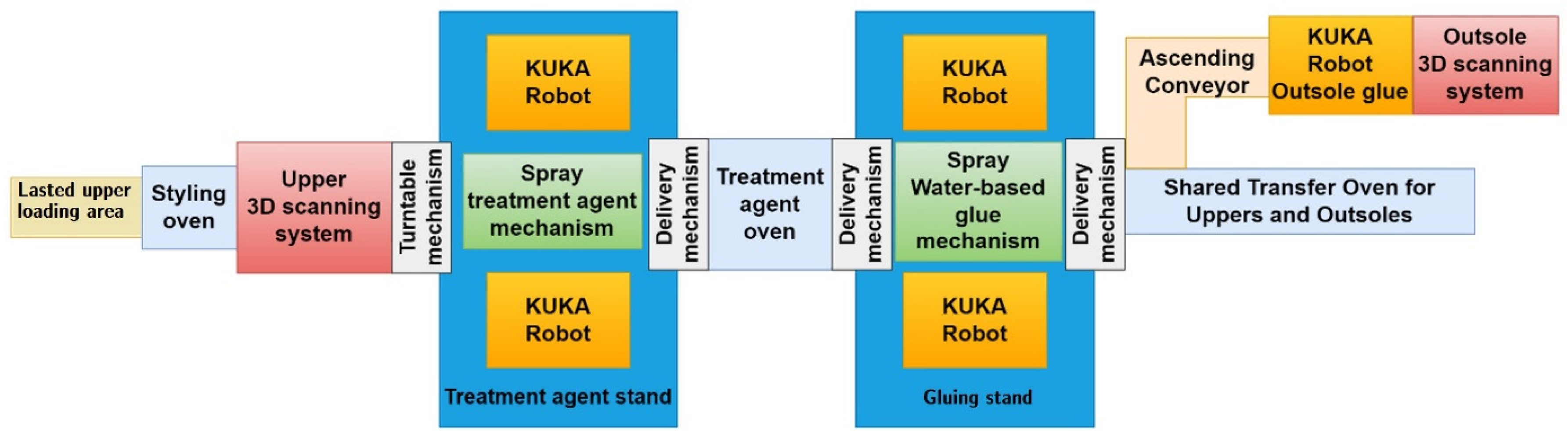
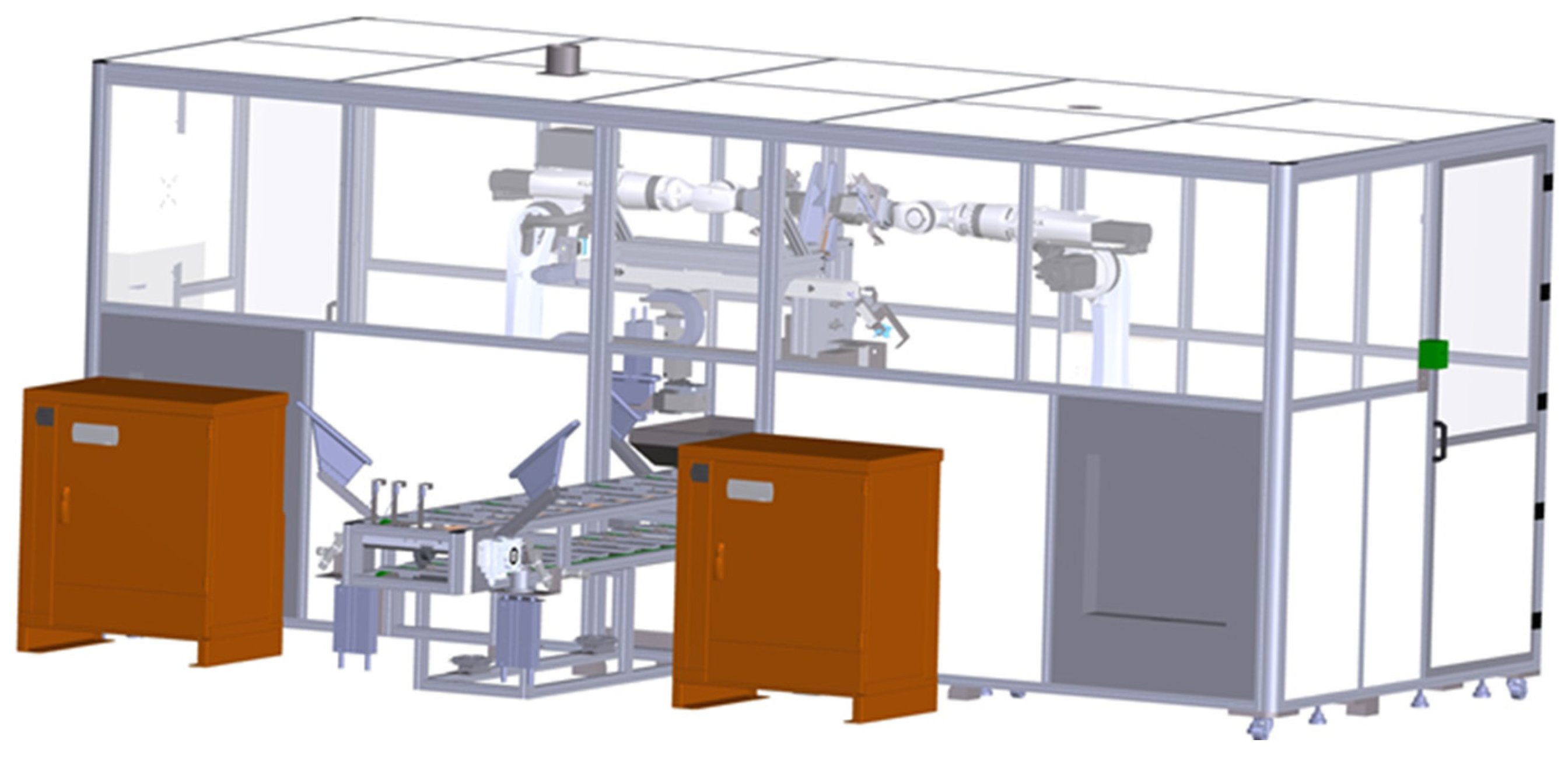
The hardware architecture of this system includes a laser triangulation-based 3D scanning system, four six-axis robotic arms (two for the treatment agent coating and two for the water-based adhesive coating), a conveyor system, a lasted upper transfer turntable, three lasted upper transfer mechanisms, and several drying ovens. The lasted upper refers to the upper part of a shoe after it has been stretched and shaped over a “last” (a foot-shaped mold) during the shoemaking process. Additionally, the main control computer supervises the entire production line, including the operation of the robotic arms. The overall hardware system architecture is depicted in
Figure 4, and the functions of each component are described in the following subsections.
3.1. Loading Area and Oven
As shown in
Figure 4, the operator first places the lasted upper onto the conveyor line at the lasted upper loading area. Since the lasted upper has been pre-sprayed with water, it passes through the first (styling) oven during transportation. This oven evaporates the moisture inside the upper, which not only helps shape the upper but also facilitates the treatment agent at the next station to more effectively penetrate into the gaps of the upper fabric.
3.2. Three-Dimensional Scanning System
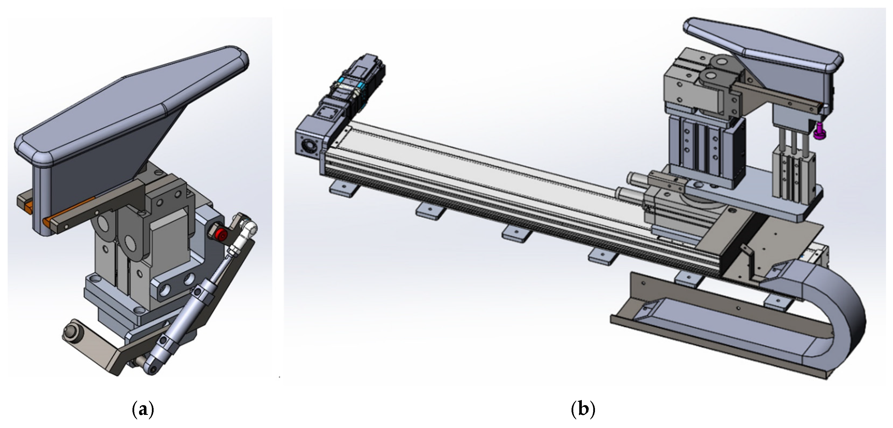
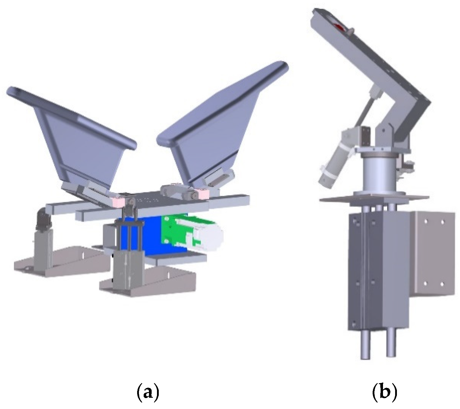
In the production line, the transfer of lasted uppers between stations, 3D scanning at the scanning station, and coating at the treatment agent and water glue stations all require the lasted uppers to be clamped for operation. Therefore, a specialized clamping mechanism was designed based on the shape of the shoe last, as shown in
Figure 5a. This custom fixture uses a cylinder to drive the clamping jaws and position pins for securing the shoe last in place. With this design, the custom clamping mechanism facilitates the transfer, scanning, and coating operations. After exiting the first oven, the lasted upper is gripped by a pneumatic gripper (
Figure 5b) and transferred to the 3D scanning system. This system is composed of a transfer platform designed for the lasted upper and a distance measurement unit based on laser triangulation.
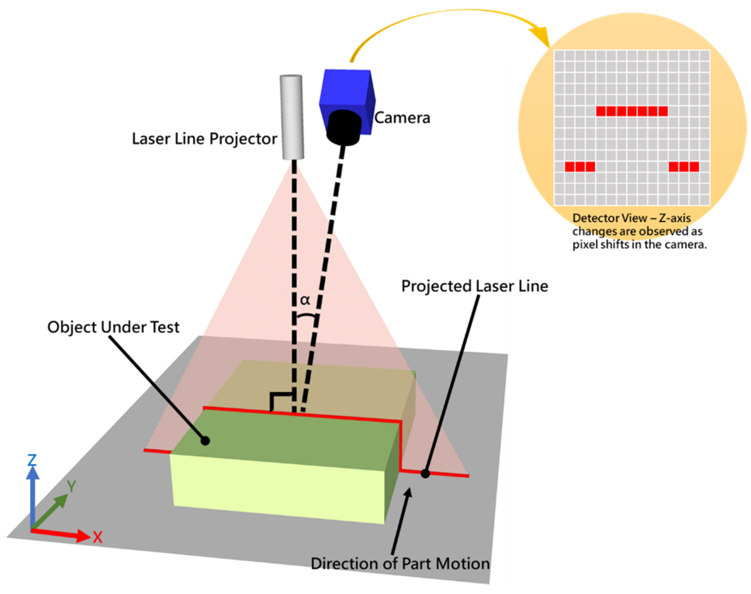
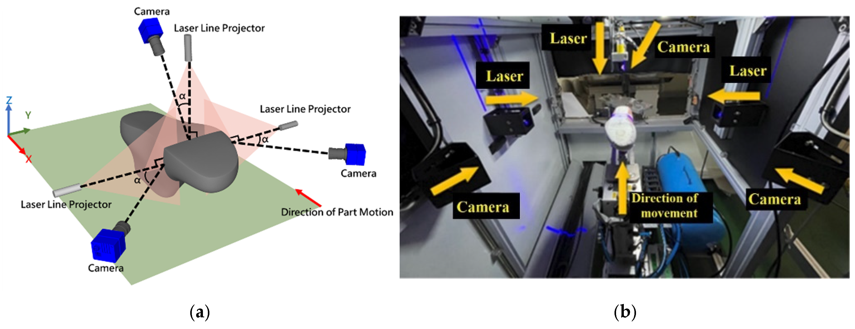
To reduce costs, the 3D scanning system employs a self-developed laser triangulation technique to capture the geometry of the upper and reconstruct its 3D model. This system is constructed by setting up three laser triangulation systems, each composed of a camera and a line laser, on the two sides and the top of the lasted upper. Three laser beams from different directions form three lines, two of which are parallel, and the third one (top) is perpendicular to both, and three laser lines form a common plane, as shown in
Figure 6a. The pneumatic gripper holds the lasted upper, and the transfer platform moves it while synchronized signals from the transfer system trigger the camera to capture the laser lines on the upper. Putting these components all together, the overall system implemented is shown in
Figure 6b.
The system simultaneously scans the left and right sides, as well as the bottom of the upper. The data from the three sets of scans are integrated to acquire the complete 3D information of the upper. This enables the real-time generation of 3D models for various shoe designs, allowing the system to determine the precise adhesive spray positions and angles tailored to each shoe model. It ultimately generates a customized spray path for the robotic arm. Once the path is constructed, the rotary table mechanism transfers the lasted upper to the next station for treatment agent coating.
3.3. Rotational Mechanism and Transfer Mechanism
A multi-axis transfer device is installed between the 3D scanning station and the treatment agent station. After scanning is completed at the 3D scanning station, the robotic arm at the treatment agent station cannot directly retrieve the shoe last from the gripper at the 3D scanning station. Therefore, a mechanism that has rotation, translation, and tilting functions (as shown in
Figure 7a) is required to firstly rotate the shoe last and then translate and tilt it for the gripper jig on the robotic arm (see
Figure 5a) to grip it.
After the treatment agent has been applied, another fixture is needed to receive the shoe last detached from the six-axis robotic arm, as shown in
Figure 7b. It then tilts down to a level position, and a pneumatic clamp takes it back onto the conveyor. These devices are used at the adhesive spraying station.
3.4. Treatment Agent and Water-Based Adhesive Coating Station
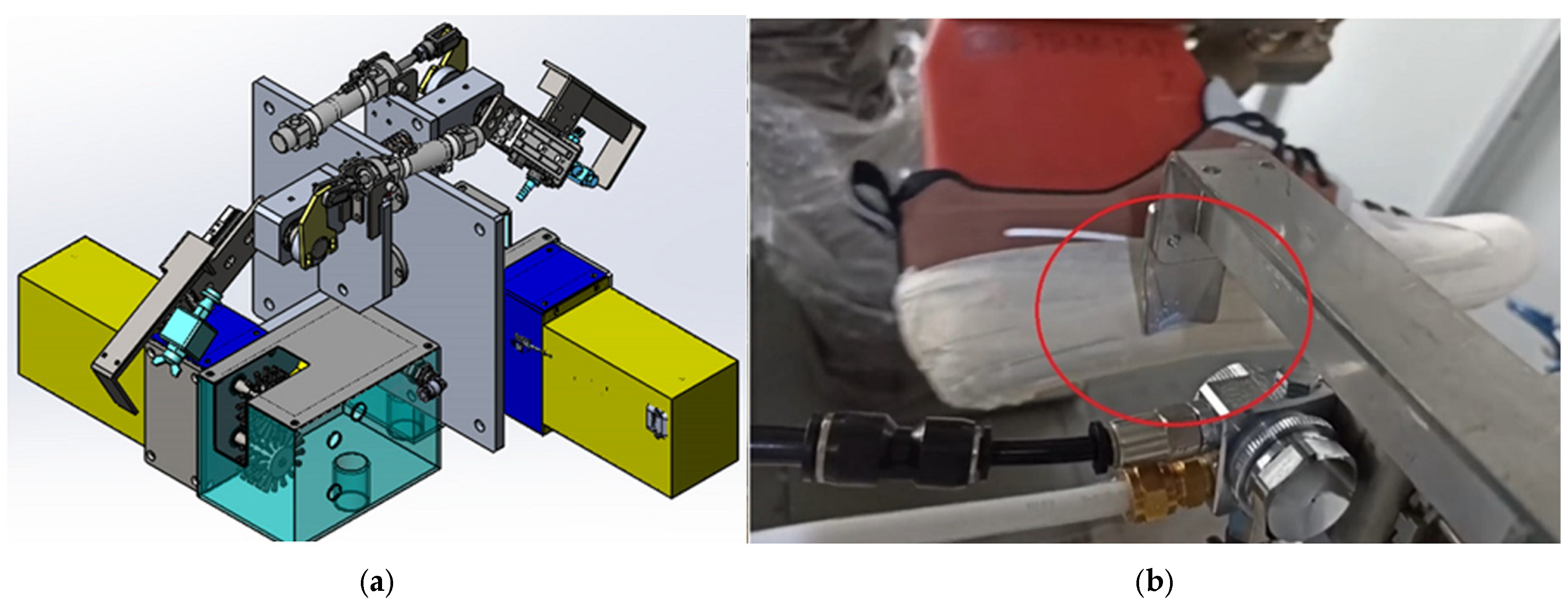
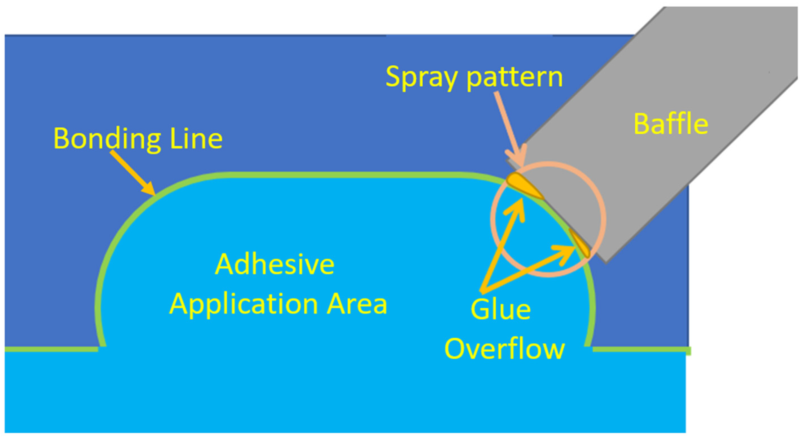
At the treatment agent station, the robotic arm uses a pneumatic gripper to hold the lasted upper and executes the spraying operation along the path generated in the previous stage. To precisely control the coating area, the system adopts a fixed spray gun (
Figure 8a) while the robotic arm maneuvers the lasted upper close to the spray baffle for coating, as highlighted within the circle in
Figure 8b. In this study, the term spray baffle refers to a fixed mechanical structure positioned in front of the spray nozzle. Its primary function is to constrain the adhesive spraying direction, guide the application path, and prevent overspray or adhesive overflow onto unintended regions of the shoe upper. During the spraying process, the robotic arm moves the shoe last close to the spray baffle to ensure proper alignment and uniform adhesive application.
This method differs from the conventional approach of fixing the lasted upper in place and having the robotic arm hold the spray gun for spraying. Although the latter is faster, it is very challenging to achieve precise control over the coating area. Moreover, the lasted upper is usually sprayed while positioned upside down in the latter approach, and there is a risk of the residual spray agent flowing downward onto the upper surface.
After completing the treatment agent coating, the transfer mechanism returns the lasted upper to the conveyor line, which then delivers it to the second oven for drying. The subsequent water-based adhesive coating station performs the same actions as the treatment agent station. Note that, since the outsole production line applies adhesive at a faster rate than the upper production line, the treatment agent and adhesive spraying stations for the upper are designed with two parallel lines: one dedicated to processing the right shoe upper and the other to the left, as illustrated in
Figure 9.
3.5. Shared Oven and Bonding Area
After completing the adhesive spraying process, the water-based adhesive station transfers the lasted upper into the third-stage oven, which is shared by both the lasted upper and the outsole. In this oven, the outsoles are conveyed along the upper level, while the lasted uppers move along the lower level. At the oven’s exit, personnel retrieve both components for bonding, thereby finalizing the entire adhesive application process.
4. Software System
The software system for automated adhesive application on lasted uppers is architected in two parts, each deployed on a separate computer. One computer functions as the main controller, managing the overall production line—including the user interface—and coordinating the robotic arm. The other is an industrial PC dedicated to the 3D modeling of the lasted upper and adhesive spray path planning. Communication between the two systems is synchronized via a custom protocol. This paper focuses exclusively on the results of 3D modeling and path planning.
4.1. Three-Dimensional Modeling of the Lasted Upper
In the 3D scanning system described in
Section 3.2, three cameras are employed to acquire laser-line images from the left, right, and top perspectives. Each image capture yields a single laser line representing the surface height profile at a specific location. To overcome this limitation, the system integrates a shoe last transfer platform (
Figure 5b) capable of grasping and repositioning the shoe last. This enables the cameras to continuously acquire sequential images from different positions. By aggregating the height data captured by the three scanning modules, individual 2.5D depth maps of the lasted upper are generated from each respective view. These depth maps are then merged to reconstruct a unified 2.5D representation of the lasted upper’s surface geometry.
4.1.1. Image Acquisition
The scanning process begins when the main control system instructs the scanning module to initiate image acquisition. The shoe last transfer platform then clamps and moves the lasted upper, during which a trigger generation module synchronizes the camera captures with the platform’s motion. Upon reaching the end position, the system signals the scanning module to complete the process.
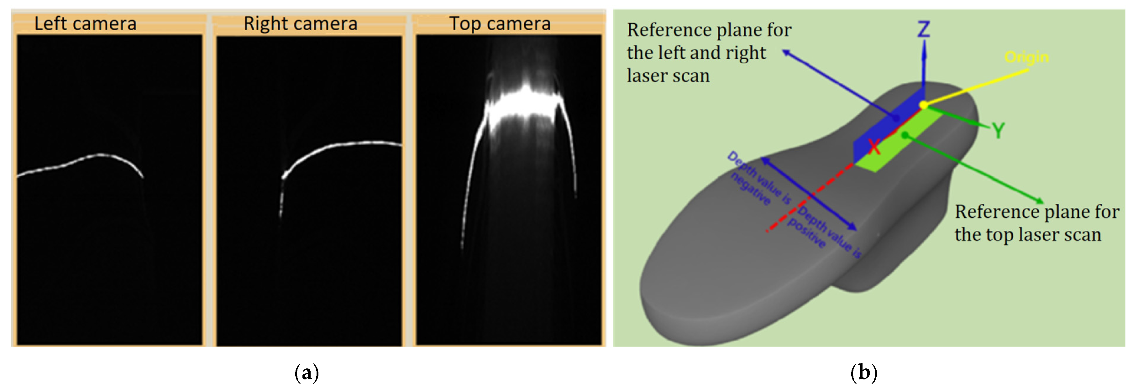
To accurately define the adhesive application areas—located on the bottom and the curved sidewalls of the lasted upper—three scanning setups are employed, as shown in
Figure 5, to capture views from the left, right, and bottom. This configuration enables the system to generate a complete 2.5D model of the lasted upper in a single scanning cycle, covering both the side and bottom surfaces. A sample image captured during this process is shown in
Figure 10a.
The innovation of our work lies in the integration of three laser-line triangulation modules mounted at different angles, which enables the precise and robust 3D reconstruction of complex curved lasted uppers under challenging industrial conditions. This multi-angle configuration minimizes occlusions and blind spots and allows us to capture the full bonding profile required for high-accuracy robotic adhesive spraying.
When constructing a 3D model using the three laser triangulation systems, a common reference plane must be established to unify the height measurements. As shown in
Figure 10b, the first reference plane—defined as the X-Z plane with a height value of 0 mm—is located between the left and right laser setups. Height values from the left and right scans are assigned negative and positive signs according to the direction of the
Y-axis in the figure. Additionally, a second reference plane, the X-Y plane, is defined perpendicular to the left–right baseline to serve as the 0 mm reference for the top-view laser. This dual-plane calibration allows all three systems to perform height measurements within a unified coordinate framework.
After establishing the reference planes, the laser-line image data must be converted into height information using geometric triangulation principles. This process involves addressing two key challenges. The first is that the laser-line images lack sufficient resolution due to the thickness of the laser stripe. The second is that the displacement of the laser line is not linearly proportional to the actual height values. The following sections detail the methods employed to overcome these issues.
4.1.2. Precise Laser-Line Localization
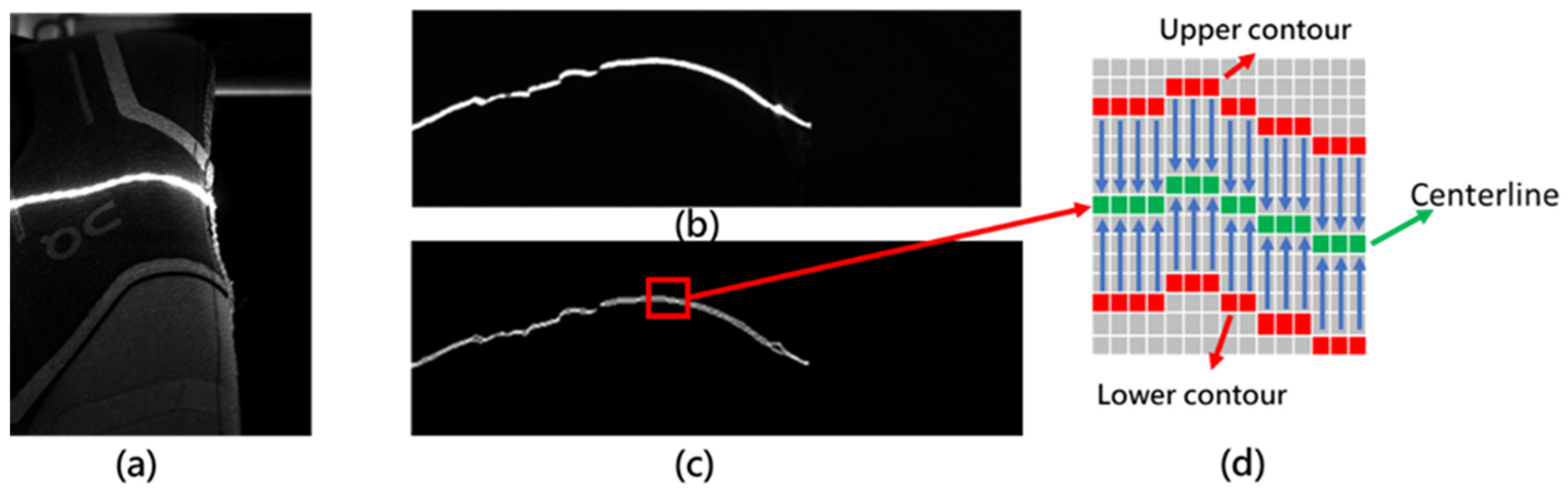
When the laser line is projected onto the lasted upper, it is necessary to adjust the camera’s aperture and exposure time to capture a sufficiently clear laser image while maintaining compatibility with the required production line speed. As shown in
Figure 11a, although the laser image appears clear, the laser stripe remains too thick to enable precise localization. To improve accuracy, adaptive thresholding is first applied for binarization, followed by morphological closing and contour-tracing techniques [
24]. These image processing steps extract the contour edge points of the laser stripe, as illustrated in
Figure 11b,c.
Subsequently, based on the extracted upper and lower contour edge points, the laser stripe’s centerline is computed by determining the midpoint between the two edges in each image row. This approach assumes a symmetrical laser intensity distribution, allowing the centerline to represent the geometric center of the stripe’s visible width. The resulting centerline provides a subpixel-accurate estimation of the stripe position and serves as the basis for calculating displacement values, as illustrated in
Figure 11d. In cases where the lasted upper exhibits complex textures or surface patterns, small gaps may appear along the extracted contours. As these discontinuities are typically minor, they can be effectively filled using linear interpolation.
4.1.3. Transformation Curve for Displacement to Height Conversion
Through the aforementioned thinning process, a precise centerline of the laser stripe is obtained, representing the pixel displacement relative to a defined reference. The next step involves converting this displacement into an actual height value using geometric triangulation. However, due to the nonlinear projection geometry inherent in laser triangulation systems, the horizontal displacement of the laser stripe is not linearly proportional to the corresponding surface height.
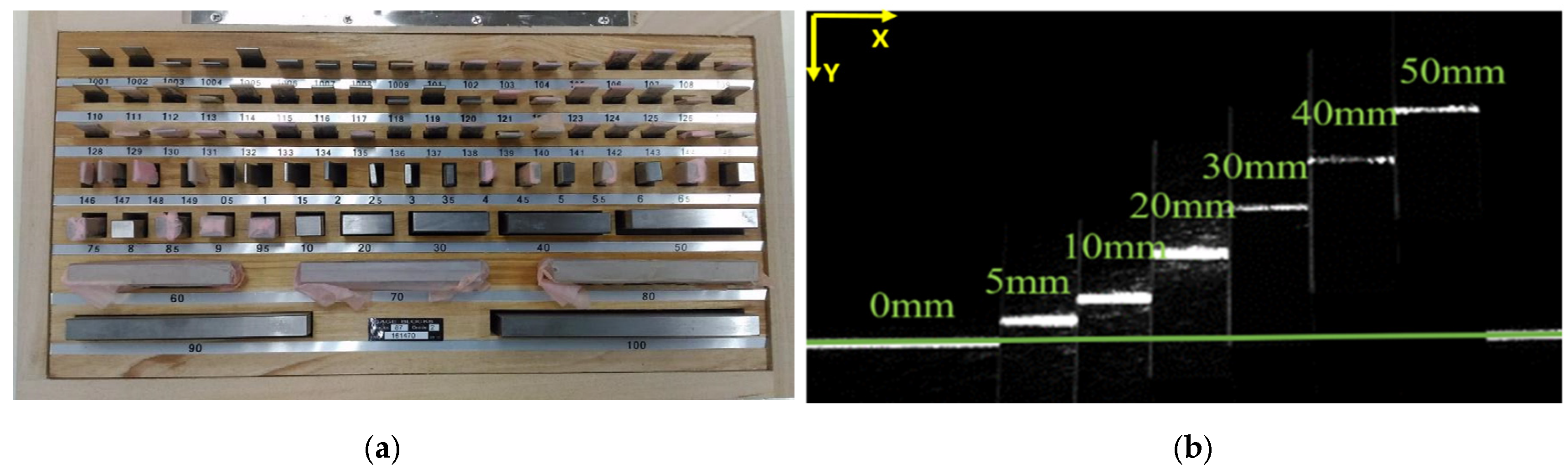
To address this, a calibration procedure is conducted using 650-series industrial-grade gauge blocks manufactured by the U.S. precision tooling company Griffin, as shown in
Figure 12a. These blocks serve as reference objects to establish the mapping between pixel displacement and physical height. For each gauge block of known height, the corresponding laser stripe position is recorded. As illustrated in
Figure 12b, the imaging position of the laser stripe shifts with height—higher gauge blocks result in lower
y-axis coordinates in the image. This inverse relationship is later modeled using polynomial regression to form the basis of the height-displacement conversion function.
Once the calibration curve is established, it is applied to the centerline data obtained from the lasted upper to compute the relative height of each point with respect to the reference plane.
During the calibration process, images can only be acquired using a limited number of gauge blocks with fixed heights. However, the lasted upper surface features continuous height variations. To address this, interpolation is employed to establish a conversion function between displacement and height based on a finite set of reference data points. Experimental results confirm that the relationship between displacement and height is nonlinear. Accordingly, the least squares method is applied to fit a quadratic polynomial to the measured data, providing a continuous mapping from pixel displacement to real-world height.
In the experiment, multiple pairs of two-dimensional data (
,
) are collected using the gauge blocks of known heights, where
denotes the physical height and
represents the corresponding pixel displacement observed in the image. These data points are then used to perform curve fitting, resulting in a second-order polynomial, as shown in Equation (1). The coefficients
,
, and
are determined via the least squares method and characterize the displacement-to-height mapping function.
The objective is to minimize the sum of squared errors between the measured data and the quadratic curve, as expressed in Equation (2).
Express the aforementioned quadratic curve in matrix form:
where the observation vector
represents the measured displacement data, the design matrix
represents the polynomial expansion of the input height values, and the parameter vector
denotes the coefficients of the quadratic function to be estimated, and they are
Using the least squares method, the objective is to minimize the sum of squared residuals, i.e.,
. The optimal solution provided by the least squares method can be obtained by solving the normal equation
. Compute
and
:
By solving
, the values of
are obtained, where
. The transformation curves for the right, left, and top scanning systems, derived from the experimental data, are presented in
Figure 13.
4.1.4. From Depth Image to 3D Model
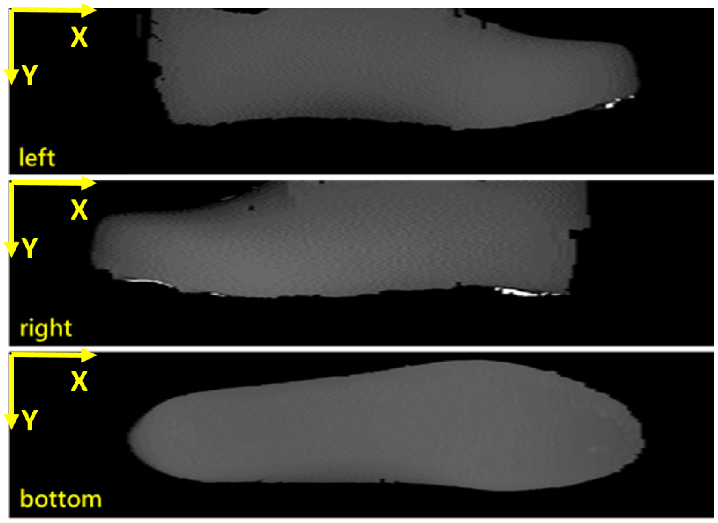
Using individual laser ranging systems, the height values obtained from the transformation curves of each laser stripe are combined to construct a 2.5D depth image of the lasted upper.
Figure 14 presents the 2.5D depth images of the left side, right side, and bottom of the lasted upper, respectively. In each image, the grayscale value of a pixel represents its corresponding height, where lower grayscale values indicate lower surface elevations, and higher grayscale values correspond to greater heights.
In the three 2.5D depth images, the grayscale values representing height have already been converted to physical units in millimeters. However, the X and Y directions, as indicated in the top-left corner of each image, are still expressed in pixel units. To obtain accurate physical dimensions, the pixel values in the XY directions must be multiplied by the corresponding pixel-to-millimeter conversion factors. This transformation is essential for reconstructing a geometrically accurate 3D model with real-world units (mm), and the process is discussed in the following section.
In the depth images shown in
Figure 14, the X-coordinate in each image corresponds to the index of the
x-th laser scan. As the lasted upper is moved by a transfer platform at a known constant speed
v (mm/s), and the camera is triggered at a fixed interval
t (s) by the signal generation module, the actual scanning interval can be calculated as
vt (mm) per trigger. Therefore, by multiplying this interval distance by the X-coordinate index
x, the
X-axis pixel position can be converted into a physical length in millimeters, enabling the accurate spatial representation of the shoe surface.
In contrast to the
X-axis, the unit conversion along the
Y-axis is more complex. While the
X-axis directly corresponds to the scan sequence and the known movement speed of the transfer platform, the physical length represented by each pixel in the
Y-axis varies with height. This variation arises from the camera’s perspective geometry and optical properties, which cause nonlinear scale changes at different heights. As the laser stripe shifts vertically due to height differences, the pixel spacing in the
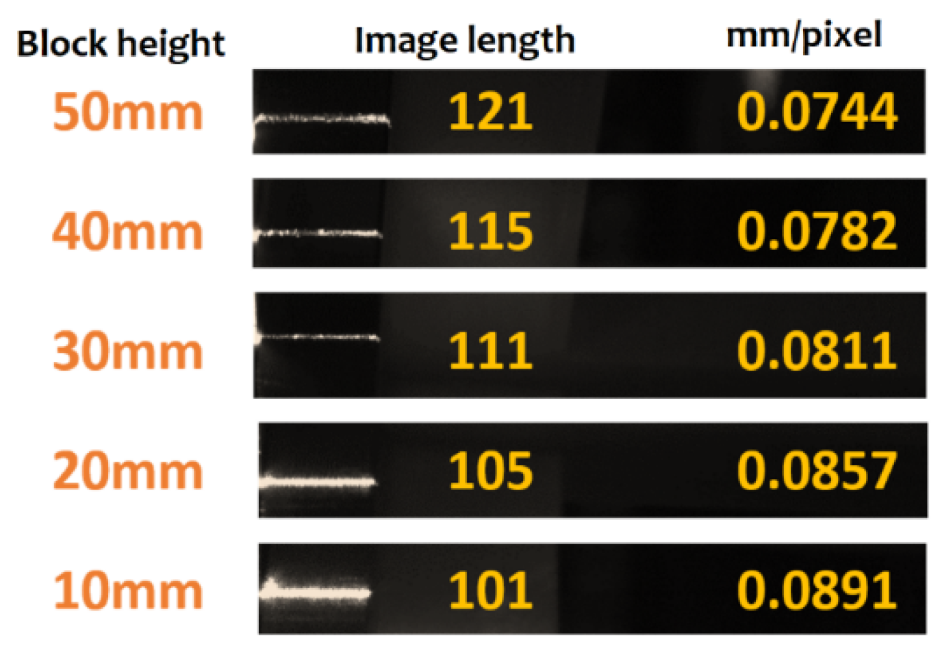
Y-axis changes accordingly. As illustrated in
Figure 15, when a gauge block with a known width of 9 mm is placed at different heights, the same physical width appears as different pixel lengths in the captured images. This observation confirms that the pixel-to-millimeter conversion factor (mm/pixel) along the
Y-axis is height-dependent and must be adjusted accordingly during reconstruction.
To address this issue, a variable Y-axis scaling function is established using calibration data collected from all three scanning systems. Similarly to the previous steps, images of reference objects—such as gauge blocks—at various known heights are captured, and the corresponding pixel-to-millimeter ratios are computed. Based on this dataset, three interpolation functions are derived for the left, right, and bottom views of the lasted upper, respectively, enabling the dynamic adjustment of the Y-axis scaling factor according to the local height. Once the unit conversions along both the X and Y axes are completed, the three sets of 2.5D depth data obtained from laser scanning can be transformed into 3D point cloud data. These point clouds are subsequently used to reconstruct a complete 3D model of the lasted upper.
As shown in
Figure 16, the point cloud model is constructed by merging three sets of point cloud data captured from the left, right, and bottom views of the lasted upper. Following model construction, the coordinate system is transformed to align with that of the robotic arm. This alignment is accomplished by applying a coordinate transformation matrix, which is described in a subsequent section. Through this transformation, the 3D point cloud is accurately mapped into the robot’s working space, enabling precise motion planning and adhesive path generation. The resulting merged point cloud provides an accurate geometric representation of the lasted upper surface, serving as the foundation for downstream adhesive application.
4.2. Path Planning
Once the 3D point cloud of the lasted upper is acquired, it can be used in conjunction with the corresponding 3D outsole model to plan the adhesive application path. In the shoe manufacturing process, the lasted upper undergoes manual stitching and lasting, resulting in greater geometric variation compared to the outsole. Therefore, to ensure precise bonding, each lasted upper must be individually scanned in 3D prior to adhesive application. In contrast, outsole variations are minimal, as their dimensions remain highly consistent throughout production. As such, the 3D models of all the available outsole sizes—both left and right—can be pre-scanned and stored in a database. These pre-scanned outsole models are then utilized during path planning for each upper, enabling accurate adhesive application regardless of individual shape differences.
The adhesive path-planning procedure involves the following steps:
Identifying the foot orientation (left or right) and size of the lasted upper.
Aligning the adhesive line of the lasted upper with the corresponding height profile of the outsole.
Extracting normal vectors along the adhesive line to guide precise robot motion and ensure proper spray direction.
4.2.1. Identifying the Upper’s Foot Orientation (Left or Right) and Size
As mentioned earlier, the 3D point cloud model of the lasted upper is generated using three scanning systems positioned at different orientations. The laser scanning system mounted above, which captures the bottom of the lasted upper, serves three main functions. First, it enables the seamless integration of laser data from the top region with those from the left and right scanning systems, thereby supporting the reconstruction of a complete 3D model of the side surfaces. Second, it provides the pixel-to-millimeter conversion factor based on variations in the surface height, ensuring an accurate 3D model of the bottom of the lasted upper. These two functions have already been utilized in the previous section.
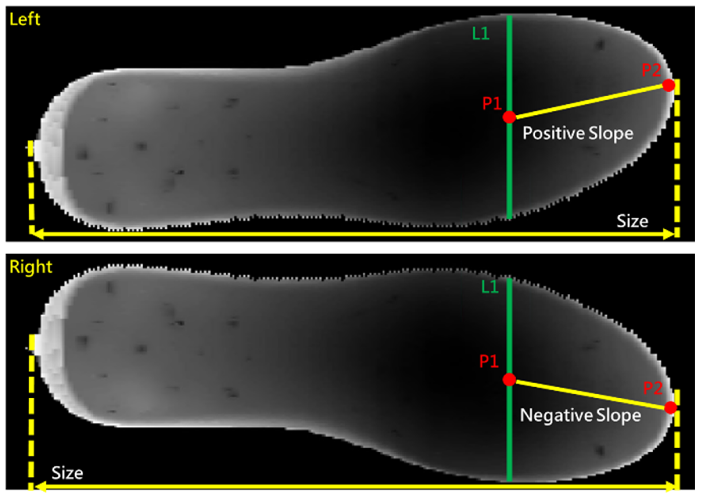
The third function is to use the depth image captured from the bottom of the lasted upper to determine its size and identify whether it belongs to the left or right foot in real time. As shown in
Figure 17, for a given depth image, the width of the lasted upper, L1, is measured at the 7/10 position of the model. By connecting its center position, P1, to the toe tip, P2, the slope of vector
is found to be positive; then, it is a left- foot upper. Conversely, if the slope is negative, the lasted upper is identified as a right foot. Additionally, by measuring the distance from the toe tip to the heel, the shoe size can be determined. Based on the estimated size and foot orientation, the corresponding outsole 3D model is retrieved from the database. The 3D model of the lasted upper is then aligned and merged with its matched outsole model. This combined geometry serves as the basis for generating the adhesive dispensing path.
4.2.2. Alignment of the Adhesive Line with the Outsole Height Profile
In traditional manual adhesive application for the lasted upper, the outsole is first temporarily fitted onto the upper, and a bonding line is manually marked around the upper to indicate the height of the outsole’s sidewall. After removing the outsole, adhesive is applied to the region below this bonding line, as illustrated in
Figure 18.
In the automated process, a similar approach is adopted. First, the bonding line must be identified on the 3D model of the lasted upper. This is accomplished by aligning the 3D point cloud of the lasted upper with its corresponding outsole model. Once the outsole’s sidewall is properly registered with the upper in 3D space, the bonding height is extracted from the outsole geometry and projected onto the upper surface, thereby defining the bonding line. Based on this bonding line, an adhesive line is then generated to guide the robotic arm’s spraying path. This ensures that the adhesive is applied only within the intended bonding region, replicating the precision of manual processes while enabling automation.
Since the 3D models of the outsole and the shoe upper are acquired using different scanning devices, they must first be registered within a common coordinate system. This alignment is critical to ensure that the outsole’s sidewall can be accurately used to define the bonding line on the upper surface. As illustrated in
Figure 19,
Figure 19a shows the depth map of the shoe upper from both sides, while
Figure 19b presents the depth map of the outsole. It is evident that a translational and rotational offset exists between the two models due to differences in their respective scanning coordinate systems. Without proper alignment, directly overlaying the outsole onto the upper results in the misalignment shown in
Figure 19c, where the geometries fail to correspond accurately.
To resolve the XY-coordinate offset between the shoe upper and outsole models, a set of key reference points is used to estimate the translational displacement. Specifically, two center points—p1 and p2—are extracted from the shoe upper point cloud at one-quarter and three-quarters of its total length, respectively, by averaging the coordinates across its width at those locations. Similarly, two corresponding points—p3 and p4—are selected from the outsole model using the same longitudinal proportions and lateral centering method. These four points form two longitudinal reference lines, one on the upper and one on the outsole, which are then used to compute the required XY translation vector for alignment.
Next, the slope
m1 and center coordinate
c1 of the line connecting points
p1 and
p2 (where
pi = (
)) on the shoe upper are computed, along with the slope
m2 and center coordinate
c2 of the line connecting points
p3 and
p4 on the outsole model. Based on these values, the translational offset
D of the outsole relative to the shoe upper in the XY plane, as well as the rotation angle
θ, can be determined using the equations provided below.
Using the computed rotation angle and translation vector, the XY coordinates of the outsole’s 3D model are corrected to align with those of the shoe upper.
Figure 19d shows the depth map after applying this alignment, illustrating the successful registration of the outsole with the upper model. Following the XY alignment, a spraying boundary line is defined on the upper surface based on the height of the outsole’s sidewall. This boundary, which varies along the contour of the upper, serves as the bonding line for adhesive path generation.
4.2.3. Surface Normal Extraction for Orientation Control in Adhesive Path Generation
To enable the robotic arm to execute adhesive spraying along the defined path after gripping the lasted upper, the path data must include not only the spatial coordinates (X, Y, Z) but also the angular information required to define the spraying orientation at each point. This orientation information is derived from the constructed 3D point cloud of the lasted upper. For each point along the spraying path, the corresponding surface normal vector is computed and used to determine the required spraying direction.
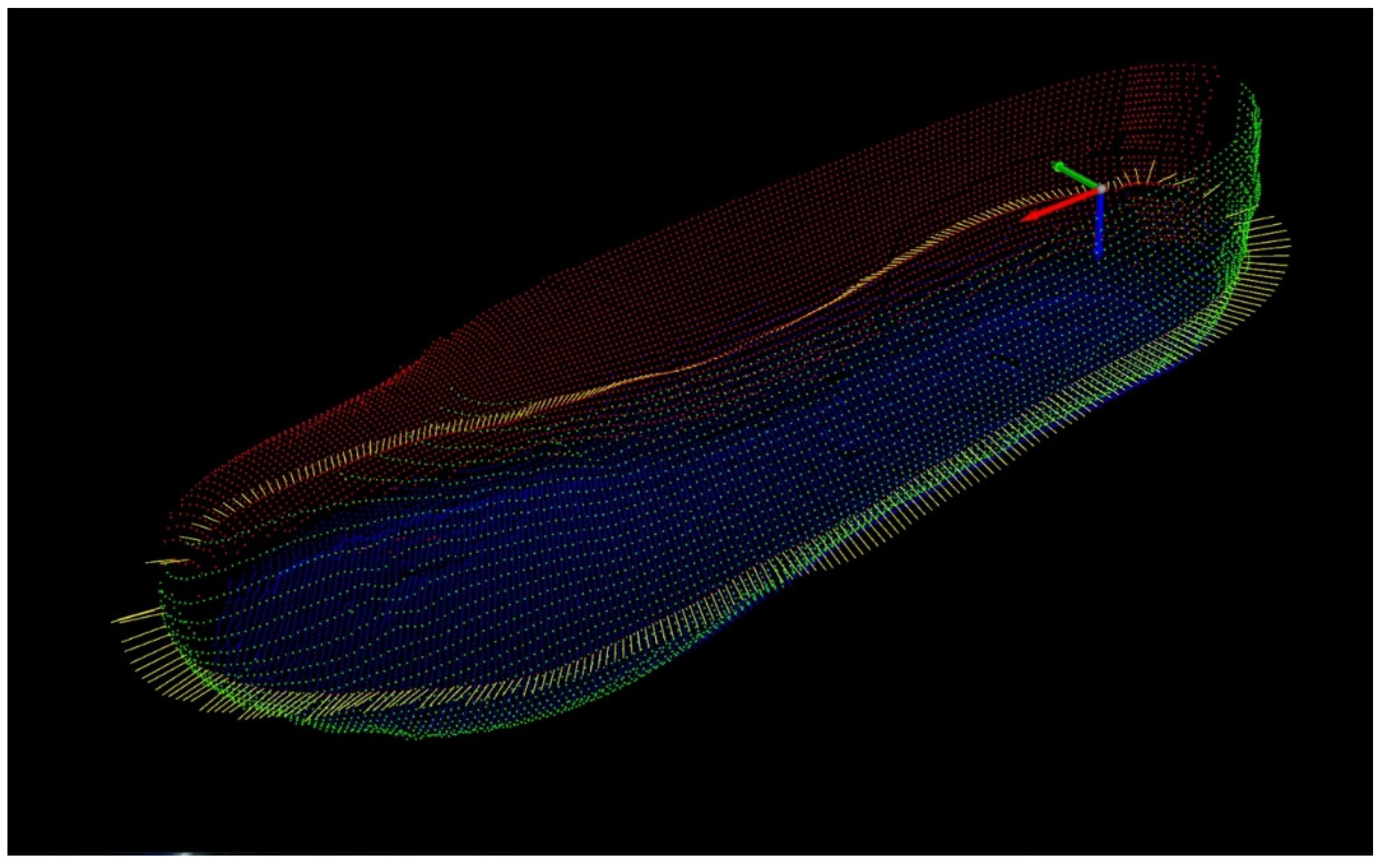
As illustrated in
Figure 20, the generated path is shown along with its associated direction vectors. These surface normal vectors are extracted along the bonding line to ensure that, during spraying, the surface of the lasted upper remains perpendicular to the fixed nozzle. The robotic arm then adjusts the orientation of the upper at each path point by calculating the Euler angles that align the local surface normal with the nozzle direction.
4.3. Coordinate Transformation from Scanning Frame to External Work Coordinate System
To accurately execute the spraying path derived from the scanned 3D model of the lasted upper, a two-stage coordinate transformation is required. The original path, defined in the scanning coordinate frame, must first be converted to the robotic tool coordinate system. Subsequently, it must be further transformed into the external work coordinate system, whose origin is located at the center of the spray baffle. The following subsections describe these two transformation processes in detail.
4.3.1. Transformation from Scanning Frame to Tool Coordinate System
The spraying path data derived for the lasted upper are initially defined in the coordinate system established by the three-sided laser scanning system described in
Section 4.1.1. However, for practical robotic execution, this coordinate system must be transformed into the tool coordinate system of the robotic arm.
In this study, the 3D scanning system and the robotic arm are located in physically separate environments, making it infeasible to directly acquire common reference points in both coordinate systems for conventional calibration. To overcome this limitation, a portable calibration fixture with known geometric features is employed as an intermediate reference object. The fixture is first placed within the scanning system’s field of view, and its pose is recorded relative to the scanning coordinate system. It is then transferred to the robotic workspace, where its spatial orientation is identified using the robot’s vision system. By capturing the pose of the same fixture in both environments, a transformation matrix—comprising rotation and translation components—is computed to convert the spraying path data from the scanning coordinate system into the robotic tool coordinate system. This coordinate transformation enables the robotic arm to accurately follow the adhesive spraying path generated from the pre-scanned 3D model of the lasted upper.
In this system, the bottom of the shoe last—gripped by the robotic arm’s end-effector—is defined as the tool coordinate system. The origin of this frame, also referred to as the tool center point (TCP), is set at a small circular hole located at the heel of the shoe last. The axes of the tool coordinate system are defined as follows: the Z-axis points outward and normal to the bottom surface of the shoe last; the X-axis points from the heel to the toe along the longitudinal direction of the shoe last; and the Y-axis is determined by the right-hand rule to complete the orthonormal basis.
4.3.2. Transformation from Tool Coordinate System to External Work Coordinate System
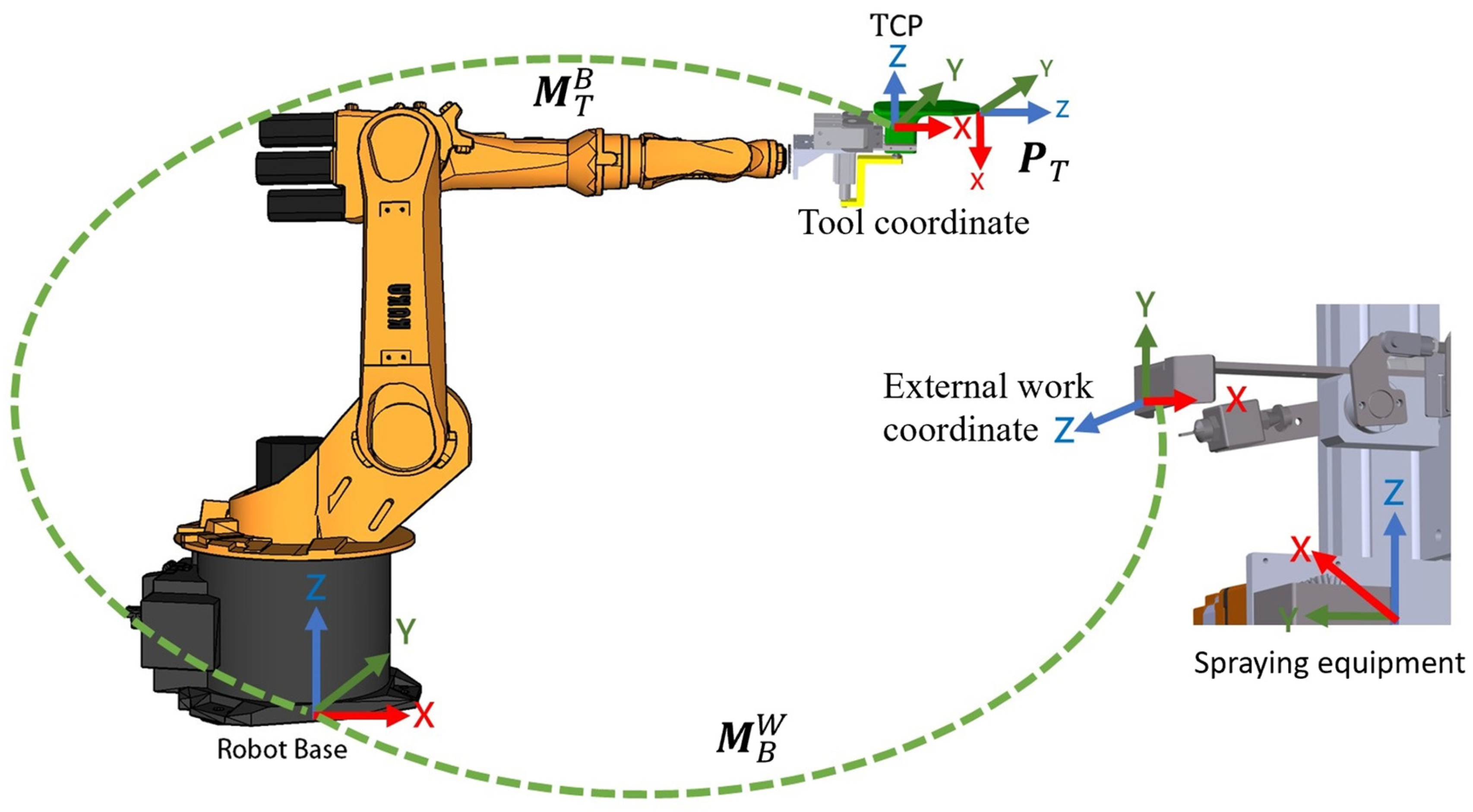
During operation, the robotic arm holds the shoe last and moves it toward a fixed spray gun. Guided by the spraying path generated by the scanning system, the arm maneuvers the shoe last such that the adhesive application area closely aligns with the spray baffle, allowing the fixed spray head to accurately apply treatment or adhesive onto the upper surface. To achieve this, the spraying path—initially defined relative to the tool coordinate system—must be converted into the external work coordinate system, whose origin is located at the center of the spray baffle. This final coordinate transformation ensures that the robotic arm can move the shoe last precisely along the pre-defined path relative to the fixed spraying apparatus.
To accurately execute the adhesive spraying path relative to the fixed spray baffle, the spraying trajectory—originally defined in the tool coordinate system (T)—must be transformed into the external work coordinate system (W). This transformation requires a sequential application of two homogeneous transformation matrices:
is the transformation from the tool frame (end-effector) to the robot base coordinate system.
is the transformation from the robot base to the external work coordinate system, whose origin is set at the center of the spray baffle.
The overall transformation from the tool frame to the work frame is given by
where
represents a point on the spraying path in the tool coordinate system.
The matrix is dynamically provided by the robot controller through its forward kinematics module based on the current joint states. Meanwhile, is established via a one-time calibration process by positioning the tool center point (TCP) at known locations on the spray baffle and recording their corresponding base frame coordinates.
As illustrated in
Figure 21, this transformation chain enables the robot to convert spraying positions defined relative to the lasted upper (held by the TCP) into precise poses relative to the external environment. It ensures that the nozzle aligns accurately with the bonding line on the upper surface during adhesive application.
4.4. Pose Calculation Based on Normal Vectors
Each point on the spraying path has an associated normal vector that defines the spraying direction in the external work coordinate system. The robotic arm performs the spraying operation along the path defined on the surface of the lasted upper, while the fixed spray tool must remain aligned with the surface normals to ensure uniform adhesive coverage.
The pose of the robotic arm at each path point is typically represented by a combination of position and orientation, where the position is already defined by the transformed path points. The orientation is computed based on the local surface normal vector and the tangent vector along the path. To achieve this, the normal vector and tangent vector are combined to construct a local orthonormal frame, which is then converted into ZYX Euler angles to represent the desired orientation. These Euler angles are used as inputs to the robot controller to achieve accurate pose execution. The computational steps for determining the Euler angles are as follows:
Let represent one of the path points in with the associated normal vector , and is its next path point.
After converting the surface normal vector at each point on the spraying path into ZYX Euler angles, the resulting position and orientation can be transmitted to the robotic arm for execution. Each computed spraying point is formatted into the KUKA robot’s E6POS structure, which encapsulates a complete six-dimensional pose comprising both position and orientation. The ZYX Euler angles (roll, pitch, yaw), derived from the local surface frame, are directly mapped to the A, B, and C components of the E6POS structure, respectively. This enables the robotic arm to follow the adhesive path with precise orientation control, ensuring that the fixed spray head remains perpendicular to the shoe surface throughout the operation.
5. Experimental Results
This section presents the experimental validation of the proposed automated gluing system for lasted uppers. To evaluate the feasibility of the proposed automated gluing system under realistic production conditions, a comprehensive implementation test was conducted using a sports casual shoe produced by the Fulgent Sun Group for the Swiss brand On, as illustrated in
Figure 22. The upper of this shoe features smooth yet irregular surface curvatures.
In traditional manual adhesive application, the outsole is first temporarily pressed against the lasted upper, allowing the operator to trace a bonding line along the edge of the outsole wall. Adhesive is then applied manually to the region below this line. To automate this process, the system must first identify the bonding line equivalent to that drawn manually. As described in previous sections, this is achieved by constructing accurate 3D models of the lasted upper and outsole, aligning them in 3D space, and generating the adhesive spraying path accordingly. The implementation details, along with the corresponding results and observations, are presented in the following subsections.
5.1. Front Stage: Loading/Drying and 3D Scanning
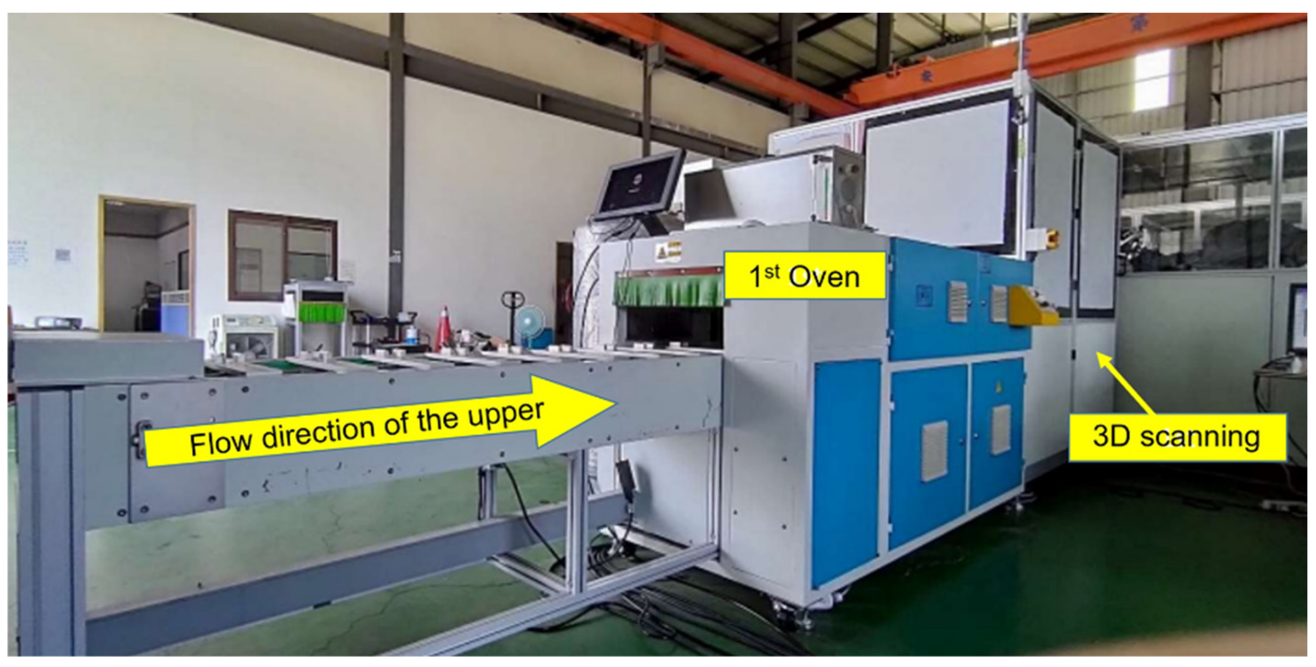
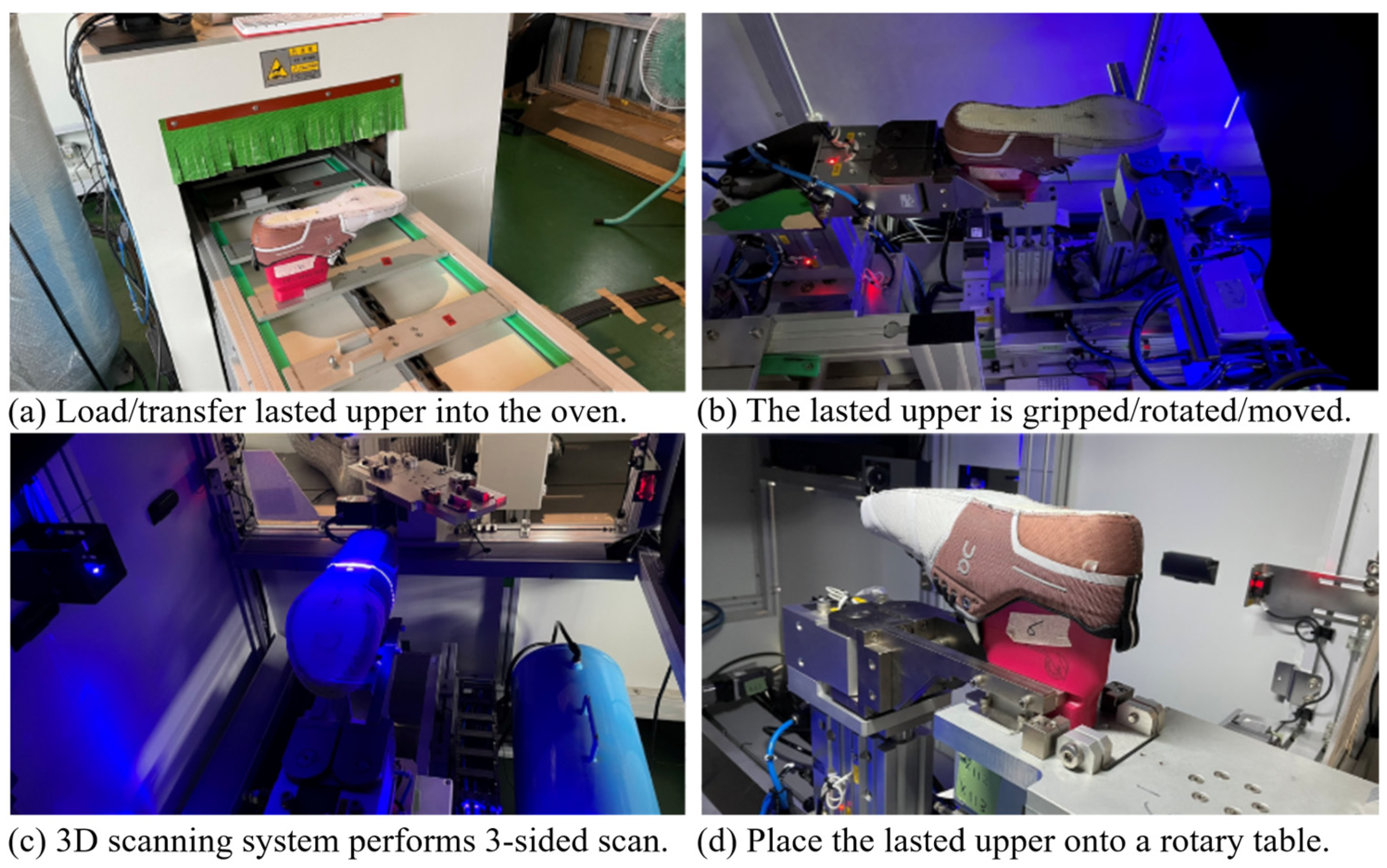
The appearance of the first operational stage is shown in
Figure 23. The process begins with placing the lasted upper onto the loading station, which then advances and enters the first drying oven for preliminary treatment, as illustrated in
Figure 24a. Upon completion of the drying process, the lasted upper is transferred to the 3D scanning station via a motorized platform. There, it is gripped, rotated, and repositioned to initiate scanning, as shown in
Figure 24b.
Once the lasted upper is properly positioned, the main control system triggers the 3D scanning system to perform a three-sided scan of the object—capturing the left, right, and top views simultaneously—as depicted in
Figure 24c. During scanning, the system also determines the shoe size and left/right foot orientation. This information is concurrently transmitted to the outsole gluing line’s preparation section, allowing a matching outsole to be prepared for gluing in advance. Such coordination ensures proper alignment and seamless bonding after the lasted upper has completed adhesive application and final drying.
After the adhesive spraying path is constructed based on the scanned 3D model, the lasted upper is placed onto a rotary table by the scanning platform. It is then ready to be transferred to the next stage of the process, as illustrated in
Figure 24d.
5.2. Middle Stage: Treatment Agent and Water-Based Adhesive Spraying Station
After completing the 3D scanning process and generating the corresponding spraying path in the previous station, the lasted upper proceeds directly to the second stage, where a treatment agent (primer) and water-based adhesive are sequentially applied. This spraying station is operated by four six-axis robotic arms, arranged in two parallel pairs—one pair dedicated to spraying the treatment agent, and the other to spraying the adhesive.
The external appearance of this station is shown in
Figure 25, where the lasted upper enters from the right side and exits on the left. The reason for pairing the robotic arms is to accommodate the higher processing speed of the outsole gluing line. To keep pace with the outsole process, the system assigns the left and right lasted uppers to separate robotic arms immediately after scanning. This setup enables the near-concurrent spraying of both sides, thereby maintaining an efficient production flow without bottlenecks. The treatment agent is applied by the following steps:
The lasted upper (L.U.) is first transferred via a rotary table, where it is rotated and tilted in preparation for being gripped by the robotic arm at the primer station, as shown in
Figure 26a.
The robotic arm then grips the shoe last, maneuvers it close to the fixed spray head, and follows the spraying path generated in the previous station to apply the treatment agent, as illustrated in
Figure 26b.
Upon completion of the treatment agent spraying, the robotic arm places the lasted upper onto a supporting mechanism, as shown in
Figure 26c.
Once the lasted upper is laid flat, a transfer mechanism grips the shoe last and places it onto the conveyor system, as depicted in
Figure 26d. The lasted upper is then placed into the oven to undergo the second drying stage.
After completing the second drying stage, the lasted upper is sequentially transferred to the water-based adhesive spraying station. This station adopts the same robotic configuration as the treatment agent station, with a pair of six-axis robotic arms responsible for spraying the left and right lasted uppers, respectively. The robotic arms grip the shoe last, maneuver it close to the fixed adhesive spray head, and follow the previously planned spraying path to apply the water-based adhesive.
The spraying process mirrors that of the treatment agent station in both sequence and motion control. However, due to the viscosity and transparency of the water-based adhesive, special attention is given to ensure consistent coating coverage. After the spraying is complete, the lasted upper is placed onto a supporting platform and then transferred onto the conveyor system for the final drying stage in the shared oven.
5.3. Final Stage: Final Drying and Bonding
After the water-based adhesive is applied, the transfer mechanism places the lasted upper onto the conveyor system, which transports it into the oven for the final drying stage, as depicted in
Figure 27. At the same time, the corresponding outsole is also sent into the same oven. This shared oven is designed with two layers:
The dual-layer structure enables the parallel thermal treatment of both components while maintaining alignment between the matched pairs. Once drying is complete, the system transfers the lasted upper and its corresponding outsole to the bonding station, where manual assembly is used to attach the two components. This manual step is currently retained to ensure precise alignment and effective pressure application and to allow for the manual stretching of the upper to fit the contour of the outsole. In addition, the operator is able to remove excess adhesive (overflow) and fill in any uncovered areas (underfill) as needed, ensuring bonding quality before final setting. The entire gluing and bonding process is thereby completed.
5.4. Summary of Experimental Results
The experimental implementation of the proposed lasted upper gluing system demonstrated the feasibility of integrating 3D vision, robotic path planning, and multi-stage adhesive application within a real production environment. Through a structured three-stage process—comprising initial drying and scanning, treatment agent and adhesive spraying, and final drying and bonding—the system successfully automated a traditionally manual process. Each robotic station performed precise manipulation and spraying based on customized 3D path planning, while synchronization with the outsole line ensured seamless assembly preparation.
Although the final bonding step is currently performed manually to accommodate variability in shoe profiles and ensure alignment accuracy, the system layout has been designed with future robotic integration in mind. Overall, the results validate the system’s ability to support flexible and efficient adhesive application for footwear manufacturing.
7. Conclusions
This study presents a fully automated lasted upper gluing system that integrates 3D vision, six-axis robotics, fixed spraying, thermal ovens, and synchronized peripherals to replace manual adhesive application. Using a custom-built 3D scanning platform, the system reconstructs each lasted upper in real-time and generates customized spraying paths. These are executed by robotic arms with high repeatability and stable orientation, achieving consistent adhesive coverage while reducing labor and ergonomic risks. Experimental results showed that most adhesive applications remained within the ±1 mm deviation—meeting industrial standards. Minor deviations, especially near the toe cap, resulted from geometric mismatch between the baffle and curved bonding lines, suggesting areas for design refinement.
Future improvements will target adaptability to complex geometries, including enhanced baffle design, refined robotic trajectories, and real-time path adjustment. Additionally, replacing the current laser-based scanning modules with compact 3D cameras (e.g., Intel RealSense D405) is under consideration to simplify hardware integration and improve flexibility. Further reductions in cycle time and energy consumption will also be explored, including optimizing adhesive properties to shorten drying time, which could potentially improve production efficiency by up to 40%. The system has been successfully deployed in a real factory line in Hanoi, Vietnam, demonstrating its industrial viability.


