Article

Study on Elastoplastic Damage and Crack Propagation Mechanisms in Rock Based on the Phase Field Method

by
Jie Zhang
1,2,
Guang Qin
1,* and
Bin Wang
1,2
1
College of Energy and Mining Engineering, Xi’an University of Science and Technology, Xi’an 710054, China
2
Key Laboratory of Mine Mining and Disaster Prevention in West China, Ministry of Education, Xi’an University of Science and Technology, Xi’an 710054, China
*
Author to whom correspondence should be addressed.
Appl. Sci. 2025, 15(11), 6206; https://doi.org/10.3390/app15116206
Submission received: 1 May 2025 / Revised: 28 May 2025 / Accepted: 28 May 2025 / Published: 31 May 2025

Abstract

:
To overcome the limitation of traditional elastic phase field models that neglect plastic deformation in rock compressive-shear failure, this study developed an elastoplastic phase field fracture model incorporating plastic strain energy and established a coupling framework for plastic deformation and crack evolution. By introducing the non-associated flow rule and plastic damage variable, an energy functional comprising elastic strain energy, plastic work, and crack surface energy was constructed. The phase field governing equation considering plastic-damage coupling was obtained, enabling the simulation of the energy evolution in rock from the elastic stage to plastic damage and unstable failure. Validation was carried out through single-edge notch tension tests and uniaxial compression tests with prefabricated cracks. Results demonstrate that the model accurately captures characteristics such as the linear propagation of tensile cracks, the initiation of wing-like cracks under compressive-shear conditions, and the evolution of mixed-mode failure modes, which are highly consistent with classical experimental observations. Specifically, the model provides a more detailed description of local damage evolution and residual strength caused by stress concentration in compressive-shear scenarios, thereby quantifying the influence of plastic deformation on crack driving force. These findings offer theoretical support for crack propagation analysis in rock engineering applications, including hydraulic fracturing and the construction of underground energy storage caverns. The proposed plastic phase field model can be effectively utilized to simulate rock failure processes under complex stress states.

1. Introduction

With the increasing global energy demands and rapid infrastructure development, the investigation of crack propagation and failure mechanisms in rock engineering has emerged as a pivotal research focus in geomechanics, hydraulic engineering, and energy development [1,2,3]. In practical engineering scenarios such as hydraulic fracturing, tunnel excavation, and the construction of underground energy storage caverns, the processes of crack initiation, propagation, and penetration in rock under coupled stress-seepage fields directly influence the safety and operational reliability of engineering structures [4]. Traditional fracture mechanics approaches—including linear elastic fracture mechanics (LEFM), stress intensity factor (SIF) methods, and extended finite element methods (XFEM)—exhibit inherent limitations in the efficient simulation of dynamic crack evolution and multi-field coupling effects. These limitations principally stem from their reliance on predefined crack paths and the computational complexity associated with handling intricate boundary conditions [5]. As a continuum-based numerical technique, the phase field method (PFM) circumvents explicit crack surface tracking through the modeling of crack evolution as a continuous distribution of phase field variables via a diffuse crack model, demonstrating significant advantages in addressing complex crack propagation under multi-field coupling [6,7,8].
Originating from the energy variational principle proposed by Francfort et al. [9], the PFM unifies crack initiation, propagation, and branching within the framework of a continuous medium framework by formulating an energy functional that incorporates both crack surface energy and elastic strain energy. Recent advancements in its application to rock mechanics include the following: Wu et al. [10] integrated thermodynamics and damage mechanics to develop a phase field model for brittle and quasi-brittle materials, resolving the length-scale dependency issue in traditional models; Zhang et al. [11] implemented a brittle material phase field fracture model in the COMSOL Multiphysics platform, clarifying through sensitivity analysis the influences of Young’s modulus and critical energy release rate on crack trajectories. However, these elastic-based models neglect the critical role of plastic deformation in compressive-shear failure, leading to overly brittle predictions and an inability to capture residual strength caused by plastic slip [12].
Parallel research efforts in plastic damage modeling have focused on characterizing irreversible deformation mechanisms. Classical plasticity theories, such as the Drucker–Prager and Mohr–Coulomb criteria, have been widely adopted to simulate shear band localization and post-yield softening in rocks [13]. Although Liu et al. [14] proposed an elastoplastic damage model for rocks, their approach relied on cohesive zone methods requiring predefined crack paths. While these studies have advanced the understanding of plastic deformation, they lack a unified framework to couple plasticity with fracture evolution, particularly in phase field formulations. A critical gap exists in the theoretical integration of plasticity theory with phase field fracture models. Existing compressive-shear phase field models predominantly rely on elastic damage theory, which only characterizes failure through strain energy decomposition and residual strength features. For instance, Wang et al. [15] developed a hydromechanical coupled phase field model but omitted plastic strain energy dissipation. Similarly, Liu et al. [16] simulated hydraulic fracturing in bedded shale using PFM yet treated the rock as purely elastic. These approaches fail to quantitatively assess the influence of plastic deformation on crack driving forces and propagation paths, significantly limiting their applicability to real-world scenarios where plastic slip dominates energy dissipation.
To address these limitations, this study introduces a novel elastoplastic phase field model that explicitly couples plastic deformation with crack evolution. Unlike conventional approaches, the proposed framework (1) integrates plastic strain energy into the total energy functional to characterize energy dissipation during plastic deformation, (2) employs non-associative flow rules to describe direction-dependent plastic flow, and (3) defines a plastic damage variable evolving with accumulated plastic work to bridge plasticity theory and fracture mechanics. This framework overcomes the fundamental limitation of elastic models by quantifying how plastic slip reduces crack propagation resistance and alters failure modes, enabling full-process simulation from elastic loading through plastic damage accumulation to unstable fracture. Consequently, it provides enhanced predictive capability for describing rock behavior in engineering applications such as hydraulic fracturing and underground cavern construction.

2. Formulation and Theoretical Derivation of the Elastoplastic Phase Field Fracture Model

Based on the elastic phase field framework, this section introduces the plastic strain tensor εp and defines its corresponding plastic strain energy ψ (εp), integrating this energy component into the total strain energy formulation to establish coupled damage–plasticity governing equations [17,18]. Additionally, by constructing a plastic potential function and a non-associative flow rule, the plastic flow and hardening/softening behavior of rock are characterized to accurately simulate the complex mechanical responses of rock during compressive-shear processes.

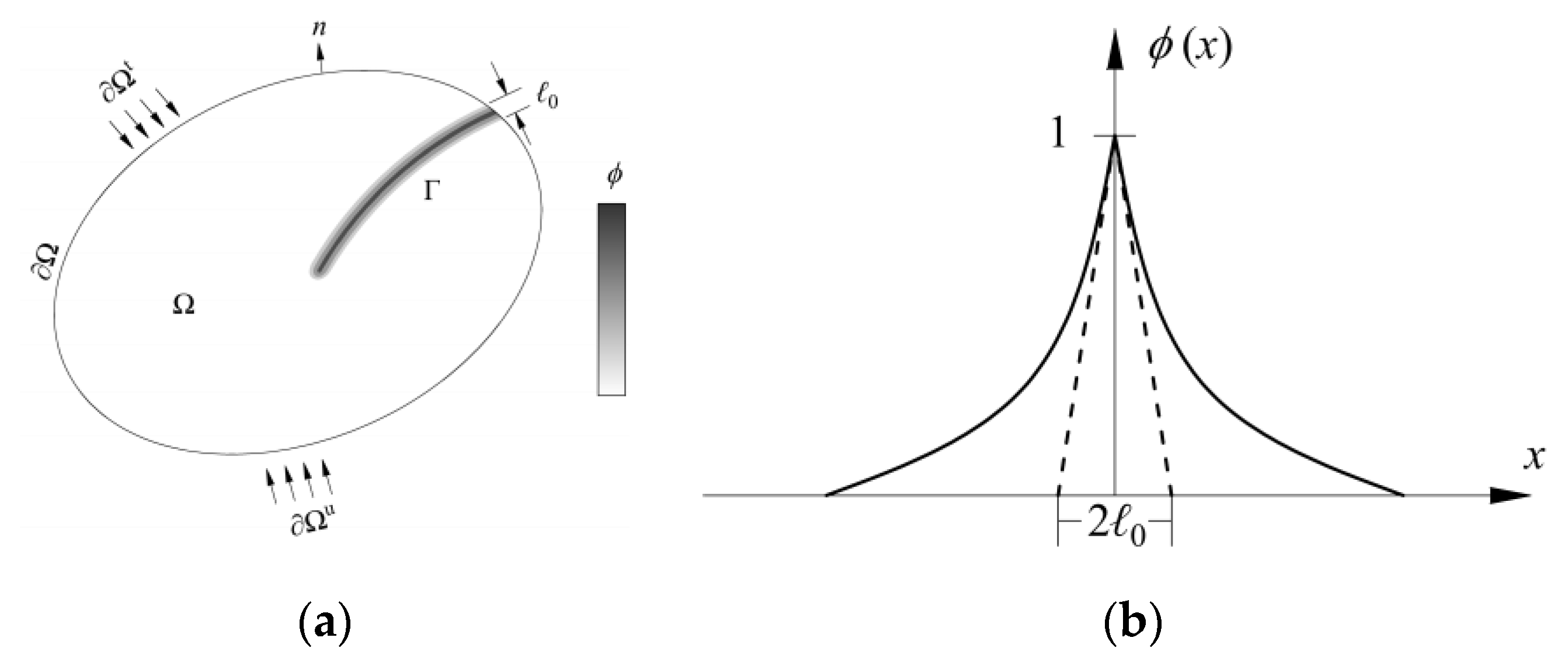
2.1. Crack Surface Energy

The fracture process in rock involves crack initiation and propagation. Consider a damaged medium occupying a domain Ω R n dim with spatial dimension ndim ∈ {1, 2, 3}, bounded by an external boundary ∂Ω and containing an internal discontinuous surface Γ, as illustrated in Figure 1a. As a non-local regularization technique, the phase field method (PFM) employs a diffuse crack model to transform sharp discontinuities from classical fracture mechanics into a continuous field description [19]. Specifically, the phase field variable ϕ and its gradient approximate the crack topology. A diffuse crack band of finite width replaces the sharp crack surface, with crack evolution governed by the continuous distribution of ϕ:ϕ = 0 corresponds to an intact material region, while ϕ = 1 indicates a fully fractured state, as depicted in Figure 1b [20].
Consistent with Griffith’s fracture theory, the fracture problem in PFM is formulated as a total system energy minimization problem, where the total system energy is a functional of the displacement field u and the phase field ϕ, reflecting the competition between elastic energy and crack surface energy [21,22]. As a gradient-type non-local model, the fracture phase field theory eliminates mesh sensitivity issues. As a regularization approach, the phase field method does not require predefined crack propagation paths and can naturally capture crack initiation, propagation, branching, and merging. Under Dirichlet boundary conditions, the one-dimensional phase field is represented by an exponential function.
ϕ = exp x l 0
In this formula, ϕ is the phase field variable, ϕ [ 0 , 1 ] , where ϕ = 0 denotes an uncracked state and ϕ = 1 signifies complete fracture; l 0 is the crack regularization length scale, governing the smooth transition of the crack profile.
Following Bourdin et al. [23], the crack surface energy can be expressed as
E f r a = Ω G c γ ( f , f ) d Ω
In this formula, G c is the critical fracture toughness; f is the spatial gradient of the phase field variable ϕ; and γ ( ϕ , ϕ ) is the regularized crack propagation energy term, defined as
γ ( ϕ , ϕ ) = 1 2 l 0 ϕ 2 + l 0 2 ϕ ϕ
In Equation (3), the first term quantifies the energy required for local crack nucleation, and the second term introduces gradient regularization to ensure smooth crack front transitions. Substituting Equation (3) into Equation (2) yields the crack surface energy:
E fra = Γ G c d Γ = Ω G c γ ( ϕ , ϕ ) d Ω = Ω G c 2 l 0 ϕ 2 + l 0 2 G c | ϕ | 2 d Ω

2.2. Elastic Strain Energy

For quasi-brittle rock materials, under the small-strain assumption, the total strain ε can be decomposed into elastic strain εe and plastic strain εp [11]
ε = ε e + ε p
During the elastic deformation stage, to address tension–compression asymmetry in strain energy-driven damage evolution, the elastic strain tensor εe is decomposed into tensile ε + e and compressive ε e components:
ε ± e = a = 1 d ε a e ±   n a n b
In this formula, ε a e denotes the principal elastic strains; na and nb represent the principal strain directions, respectively; and ε a e ± is defined via the Macaulay operator ε a e ± = ( ε a e ± ε a e ) / 2 .
In rock deformation and failure processes, material damage is predominantly attributed to local elastic tensile strains. Thus, the total elastic strain energy density during fracture can be expressed as [24]
ψ ( ε ) = g ( ϕ ) ψ + e + ψ e
In this formula, ψ + e and ψ e correspond to the elastic strain energy densities under tensile and compressive stress states, respectively.
At complete fracture ϕ = 1, tensile elastic strain energy dissipates progressively. To model this behavior, a phase field damage degradation function is introduced:
g ( ϕ ) = ( 1 δ ) ( 1 ϕ ) 2 + δ
In this formula, δ is a small regularization parameter to avoid numerical model singularity when ϕ = 1.
In engineering practice, rocks commonly experience compressive-shear stress states, exhibiting distinctive compressive-shear failure characteristics. Conventional phase field theories predominantly address tensile fracture and struggle to accurately predict compressive-shear crack propagation [25,26,27]. Theoretical analyses demonstrate that strain energy decomposition directly governs crack trajectories and propagation modes. To accurately model rock failure under prevalent compressive-shear conditions in underground engineering, the total strain energy is partitioned into three physically interpretable components: tensile strain energy—drives crack nucleation at stress concentrations; tensile-shear strain energy—governs mixed-mode crack growth under combined stresses; compressive-shear strain energy—regulates shear band formation and stable crack propagation. This decomposition accounts for the asymmetric tension–compression response of rocks: tensile stresses initiate cracks at notch tips, while compressive-shear stresses promote shear localization and post-peak strength evolution. To characterize post-failure residual strength, a compressive-shear residual strength parameter η is incorporated, modifying the elastic strain energy density function in Equation (7) to
ψ ( ε ) = g ( ϕ ) ( ψ + e , I + ψ + e , II ) + g ( ϕ ) + η [ 1 H ( t r ( ε ) ) ] [ 1 g ( ϕ ) ] ψ e
In this formula, ψ + e , I and ψ + e , II represent the volumetric and deviatoric tensile strain energy densities, respectively; ψ e denotes the compressive-shear elastic strain energy density; η is the residual strength parameter; and H(x) is the Heaviside step function
H ( x ) = 0 , x < 0 1 , x 0
The mathematical expressions for strain energy components are
ψ + e , I = 1 2 λ tr ( ε ) + 2 ψ + e , II = μ tr ε + 2 ψ e = 1 2 μ τ 2
In this formula, τ is the shear strength and λ and μ are Lamé constants, related to Young’s E modulus and Poisson’s ratio ν
λ = E ν ( 1 + ν ) ( 1 2 ν ) μ = E 2 ( 1 + ν )
Post compressive-shear failure, the shear plane orientation relative to the axial direction is well-described by the Mohr–Coulomb criterion. This criterion establishes that shear failure depends on cohesion and internal friction angle, which quantify interparticle bonding and frictional resistance. In this framework, shear strain energy regulates phase field damage evolution, bridging plasticity theory with continuum damage mechanics [28]. Under plane stress conditions, the Mohr–Coulomb shear strength τ is expressed as
τ = σ 1 e σ 2 e 2 cos φ ( σ n < 0 ) 0 ( σ n 0 )
In this formula, σ i e ( i = 1 , 2 ) are principal compressive stresses; σ n is the normal stress.
Based on the energy decomposition, the system’s elastic strain energy is reformulated as
E ela = Ω g ( ϕ ) ( ψ + e , I + ψ + e , II ) + g ( ϕ ) + η [ 1 H ( t r ( ε ) ) ] [ 1 g ( ϕ ) ] ψ e d Ω

2.3. Plastic Damage Strain Energy

The separate analysis of plastic damage in the compressive-shear phase field model of rock mechanics facilitates the clearer understanding of interaction mechanisms between plastic deformation and damage evolution, thereby supporting more precise model refinement [29,30]. The subsequent discussion addresses plastic damage definition, evolution equations, and coupling relationships.
Under isotropic hardening assumptions, the plastic strain energy Epla is generally expressed as
E pla = Ω ψ ( ε p ) d Ω
In this formula, ψ ( ε p ) represents the plastic strain energy density.
Plastic damage originates from irreversible plastic deformation in loaded rock materials, causing internal structural degradation [31]. The model quantifies plastic damage severity through a plastic damage variable Dp (Dp ∈ [0, 1]), where Dp = 0 indicates undamaged material and Dp = 1 signifies complete plastic failure. Distinct from elastic damage, Dp captures energy dissipation during plastic flow—particularly in shear bands where accumulated plastic slip reduces material stiffness and modifies crack propagation paths. Given that plastic deformation involves energy dissipation, the plastic damage evolution is defined via accumulated plastic strain energy. Assuming proportionality between damage evolution and plastic energy, the evolution rate is formulated as
d D p d t = 1 G p D d ψ ( ε p ) d t
In this formula, GpD denotes the plastic damage-related critical energy release rate; Epla is the plastic strain energy.
Following the plastic constitutive framework, the plastic strain energy Epla is derived from plastic work concepts. Assuming isotropic hardening, the plastic strain energy density is expressed as
ψ ( ε p ) = 1 2 K p ( t r ( ε p ) ) 2 + μ p t r ( ε p ) 2
In this formula, K p is the plastic bulk modulus; μ p is the plastic shear modulus; and ( ε p ) 2 denotes the squared plastic strain tensor.
Differentiating Equation (17) temporally yields the plastic strain energy rate:
d ψ ( ε p ) d t = K p tr ( ε p ) tr d ε p d t + 2 μ p tr ε p d ε p d t
Substituting Equation (18) into Equation (16) results in
d D p d t = 1 G p D K p tr ( ε p ) tr d ε p d t + 2 μ p tr ε p d ε p d t
In practical scenarios, plastic damage evolution depends on material yielding. A plastic yield function f ( σ , ε p ) is introduced to determine yielding states. When condition f ( σ , ε p ) 0 is satisfied, the material remains in the elastic state; when condition f ( σ , ε p ) > 0 is met, the material enters the plastic state, and plastic damage begins to evolve. To characterize rock plastic strain evolution, a non-associated flow rule is adopted [32]. Based on the Drucker–Prager criterion, the yield function is defined as
f ( σ , ε p ) = J 2 + α tr ( σ ) k
In this formula, J 2 is the second deviatoric stress invariant; α relates to the internal friction angle; tr ( σ ) is the volumetric stress; and k is the hardening parameter.
Integrating yielding conditions, the plastic damage evolution equation is revised as
d D p d t = 1 G p D K p tr ( ε p ) tr d ε p d t + 2 μ p tr ε p d ε p d t f ( σ , ε p ) > 0 0 f ( σ , ε p ) 0
Through the comprehensive analysis of plastic damage, the plastic damage evolution equation is derived, providing a theoretical foundation for optimizing the elastoplastic phase field coupling framework. Furthermore, the enhanced model captures the mechanical behavior and failure mechanisms of rock materials under compressive-shear loading, enabling the precise simulation of crack propagation and failure processes under multiaxial stress conditions.

2.4. Derivation of Phase Field Governing Equations and Equilibrium Equations

Existing models account for the effects of phase field variable ϕ and plastic damage Dp on crack evolution. However, their coupling interaction affects material properties and crack propagation. To address this coupling effect, the damage degradation function g (ϕ, Dp) is redefined as
g ( ϕ , D p ) = ( 1 δ ) ( 1 ϕ D p ) 2 + δ
In this formula, δ is a regularization parameter to prevent numerical singularities.
Thus, the total strain energy is then expressed as
E str = E ela + E pla = Ω g ( ϕ , D p ) ψ + e , I + ψ + e , II d Ω + Ω g ( ϕ , D p ) + η [ 1 H ( t r ( ε ) ) ] [ 1 g ( ϕ , D p ) ] ψ e d Ω + Ω 1 2 K p ( t r ( ε p ) ) 2 + μ p t r ( ε p ) 2 d Ω
Equation (22) reveals that tensile elastic energy dissipates as ϕ→1, the tensile elastic energy gradually disappears. To ensure the irreversibility of crack damage evolution, the energy takes the maximum value of the historical field variable, and we can set
+ I = max 0 t T ψ + e , I + II = max 0 t T ψ + e , II = max 0 t T ψ e
Consequently, the total strain energy is reformulated as
E str = Ω g ( ϕ , D p ) + I + + II d Ω + Ω g ( ϕ , D p ) + η [ 1 H ( t r ( ε ) ) ] [ 1 g ( ϕ , D p ) ] d Ω + Ω 1 2 K p ( t r ( ε p ) ) 2 + μ p t r ( ε p ) 2 d Ω
For quasi-static systems, energy conservation requires total potential energy to equal external work. Under body forces b and surface tractions t, the total energy Π is
Π = E str + E fra + E ext = Ω g ( ϕ , D p ) + Ι + + II d Ω + Ω g ( ϕ , D p ) + η [ 1 H ( tr ( ε ) ) ] [ 1 g ( ϕ , D p ) ] d Ω + Ω 1 2 K p ( tr ( ε p ) ) 2 + μ p tr ( ε p ) 2 d Ω + Ω G c 2 l 0 ϕ 2 + l 0 2 G c | ϕ | 2 d Ω + Ω b u d Ω + Ω t u d Ω
Taking the first variation in Equation (26) with respect to uu yields the equilibrium equation
σ + b = 0
Of these, the influence of plastic deformation needs to be considered for the stress tensor σ. The stress tensor is obtained by taking the partial derivative of the total strain energy ψ ( ε , ε p ) with respect to the strain tensor ε
σ = ψ ε = g ( ϕ ) σ + e f f + g ( ϕ ) σ e f f + η [ 1 H ( tr ( ε ) ) ] [ 1 g ( ϕ ) ] σ e f f + ψ ( ε p ) ε p
In this formula, σ + e f f and σ e f f denote effective tensile and shear stresses, respectively.
As can be seen from Equation (17), by taking the partial derivative of the plastic strain energy with respect to the strain tensor, we can obtain
ψ ( ε p ) ε p = K p tr ( ε p ) I + 2 μ p ε p
In this formula, I is the second-order identity tensor.
Plastic damage modifies material stiffness, thereby reducing crack propagation resistance. At crack tips, localized softening from Dp accumulation decreases fracture energy. To account for the effect of plastic damage on crack propagation, a correction factor β ( D p ) = 1 D p is introduced to modify the critical energy release rates G c II + and G c into G c I + β ( D p )   , G c II + β ( D p )   , and G c β ( D p ) .
Applying variational minimization, the phase field governing equation with plastic damage coupling is derived as
g ( ϕ , D p ) ϕ + I G cI + β ( D p ) + + II G cII + β ( D p ) + 1 η 1 H tr ( ε ) × G c β ( D p ) + ψ p ( ε p ) G p l 0 Δ ϕ + 1 l 0 ϕ = 0
In this formula, G cI + is the tensile critical energy release rate of the material; G cII + is the tensile-shear critical energy release rate of the material; and G c is the compressive-shear critical energy release rate of the material.

3. Numerical Implementation of Phase Field Fracture Model Based on Finite Elements

The numerical implementation of the phase field fracture model constitutes a pivotal step in investigating the fracture behavior of geomaterials, bridging theoretical frameworks with practical analysis tools. This section details finite element discretization and numerical implementation strategies to enable robust solutions for phase field fracture simulations.

3.1. Finite Element Discretization

Within the finite element framework, the displacement field is first discretized. Under small-strain assumptions, the strain tensor is derived from displacement gradients
ε = 1 2 ( u + u T )
The continuum domain undergoes spatial discretization into finite elements, interconnected via nodes [33,34]. The displacement field is approximated through shape function interpolation. For n nodes, the discretized displacement field is
u = I = 1 n N I u u I
In this formula, N I u denotes the displacement shape function for node I; u I represents the nodal displacement vector.
For two-dimensional quadrilateral elements, the bilinear shape function matrix N u is expressed as
N I u = N 1 0 N n 0 0 N 1 0 N n
In this formula, N i (i = 1, 2, … n) are bilinear shape functions, and for a quadrilateral element, the expression in the local coordinate system ( ξ , η ) are given as
N i = 1 4 ( 1 + ξ i ξ ) ( 1 + η i η )
In this formula, ξ i and η i are local coordinates of node i.
Substituting Equation (32) into Equation (31) yields the strain-displacement relation
ε = I = 1 n B I u u I
In this formula, B I u is the strain-displacement matrix, derived from the spatial derivatives of N I u .
Similarly, the phase field ϕ is similarly discretized via nodal interpolation
ϕ = I = 1 n N I ϕ ϕ I
In this formula, N I f is the phase field shape function of node I, and f I is the phase field value of node I.
In a two-dimensional problem, the phase field shape function matrix is given as
N I ϕ = N 1 N 2 N n
The phase field gradient is expressed as
ϕ = I = 1 n B I ϕ ϕ I
In this formula, B I ϕ is the derivative matrix of the phase field shape function with respect to the coordinate axes.

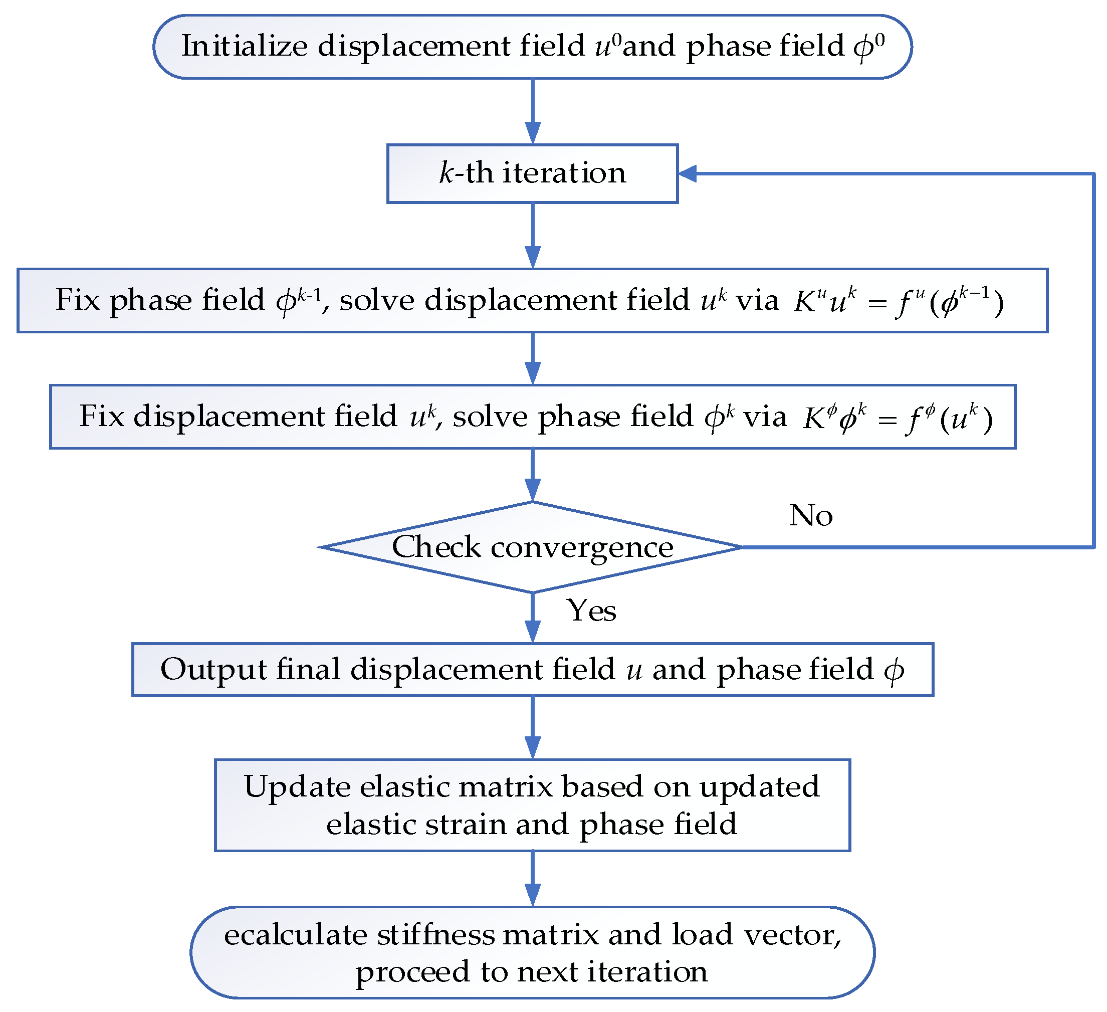
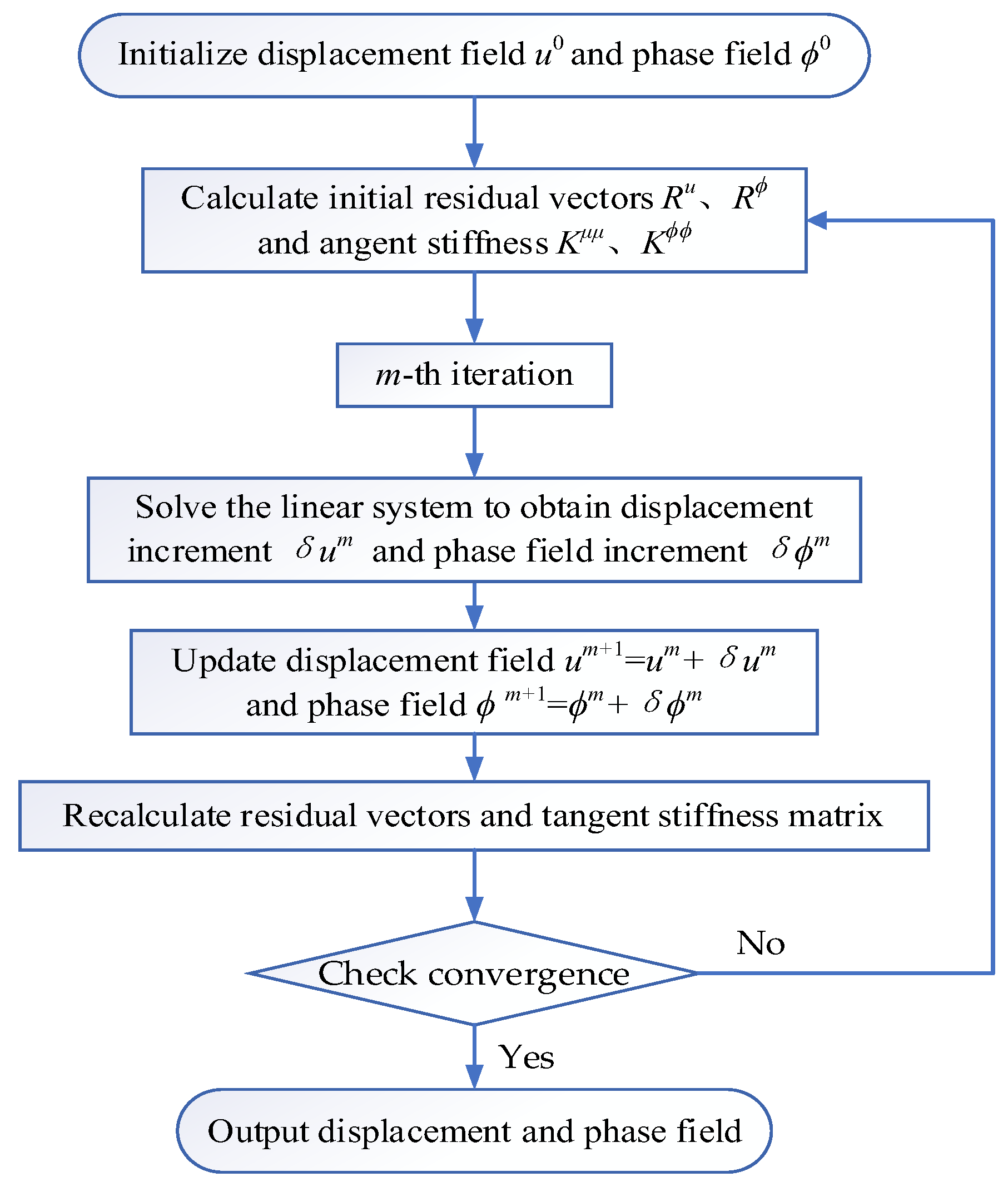
3.2. Numerical Implementation Process

Since the total potential energy of the system exhibits non-convexity with respect to the coupled phase field and displacement fields but remains convex for individual field variables, a staggered solution algorithm is implemented to ensure numerical robustness [35,36]. This decoupled approach is selected for its capability to address the non-convex energy landscape when solving displacement and phase field variables simultaneously, while leveraging convexity within each sub-problem. By alternately freezing one field and solving the other, the algorithm circumvents numerical instabilities inherent in fully coupled nonlinear systems. This strategy enhances computational efficiency by reducing equation system dimensions per iteration while maintaining solution accuracy. In practice, the governing equations are first converted to weak forms via the principle of virtual work. For instance, the displacement field u and phase field ϕ are transformed into integral forms over the solution domain, which are subsequently discretized via finite element methods to derive linear equation systems.
The discretized governing equation for the displacement field can be expressed as
K u u = f u
In this formula, K u is the stiffness matrix of the displacement field and f u is the load vector of the displacement field.
The discretized governing equation for the phase field can be expressed as
K ϕ ϕ = f ϕ
In this formula, K ϕ is the phase field stiffness matrix and f ϕ is the phase field load vector.
Thus, the specific steps of the staggered solution algorithm are shown in Figure 2.
At each time step, the elastic matrix is updated according to the current elastic strain and phase field distribution. Specifically, material damage severity is quantified via the phase field value, enabling the dynamic adjustment of elastic modulus and stiffness matrix parameters. Subsequently, the updated elastic matrix is utilized to recompute the stiffness matrix and load vector, propagating the solution iteratively until steady-state conditions are attained. To ensure numerical stability, convergence criteria enforce the following: residual force norm reduction below 10−5 × initial residual. Maximum absolute phase- field variation across nodes is less than 10−6.
The Newton–Raphson method addresses strong nonlinearities from plasticity–damage coupling, exploiting quadratic convergence near solutions to efficiently resolve challenges like crack propagation softening behavior. By linearizing residuals at each iteration, the method systematically minimizes errors between iterative and true solutions, effectively capturing abrupt stiffness changes during damage localization. For displacement field u and phase field ϕ, the authors of [24] establish a linearized system:
K μ μ 0 0 K ϕ ϕ δ u δ ϕ = R u R ϕ
In this formula, K μ μ and K ϕ ϕ are the tangent stiffness matrices of the displacement field and the phase field, respectively, and they are the functions of the displacement field u and the phase field ϕ; R u and R ϕ are the residual vectors, which reflect the difference between the current solution and the real solution. The basic principle of the Newton–Raphson iterative method is to linearly approximate the nonlinear function near the current solution and gradually approach the real solution by solving the system of linear equations. The specific iterative steps are shown in Figure 3.
Anderson acceleration is integrated to expedite convergence during iterations. This method constructs optimized search directions through linear combinations of historical residuals, significantly accelerating convergence rates. Implementation requires the storage of prior residuals and displacement increments, followed by acceleration factor computation via prescribed formulas to update field variables. The Anderson method particularly enhances efficiency in scenarios with gradual plastic damage evolution, reducing iteration counts by approximately 30% through residual recycling. This optimization renders large-scale simulations computationally feasible. The comprehensive finite element discretization and solution framework establishes a rigorous foundation for phase field fracture model implementation. Future work will extend to model validation, parameter sensitivity analysis, and innovative feature integration, culminating in a complete numerical framework for phase field fracture modeling.

4. Numerical Examples

To validate the numerical method’s accuracy, two benchmark tests were simulated and compared: a single-edge notched tensile test and a uniaxial compression test on rock with a prefabricated crack. By aligning simulation results with the existing literature, the proposed method demonstrates the precise modeling of crack propagation processes.

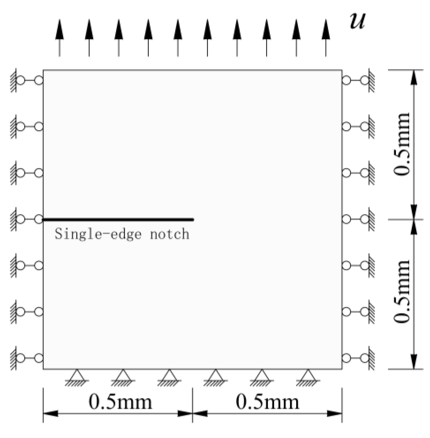
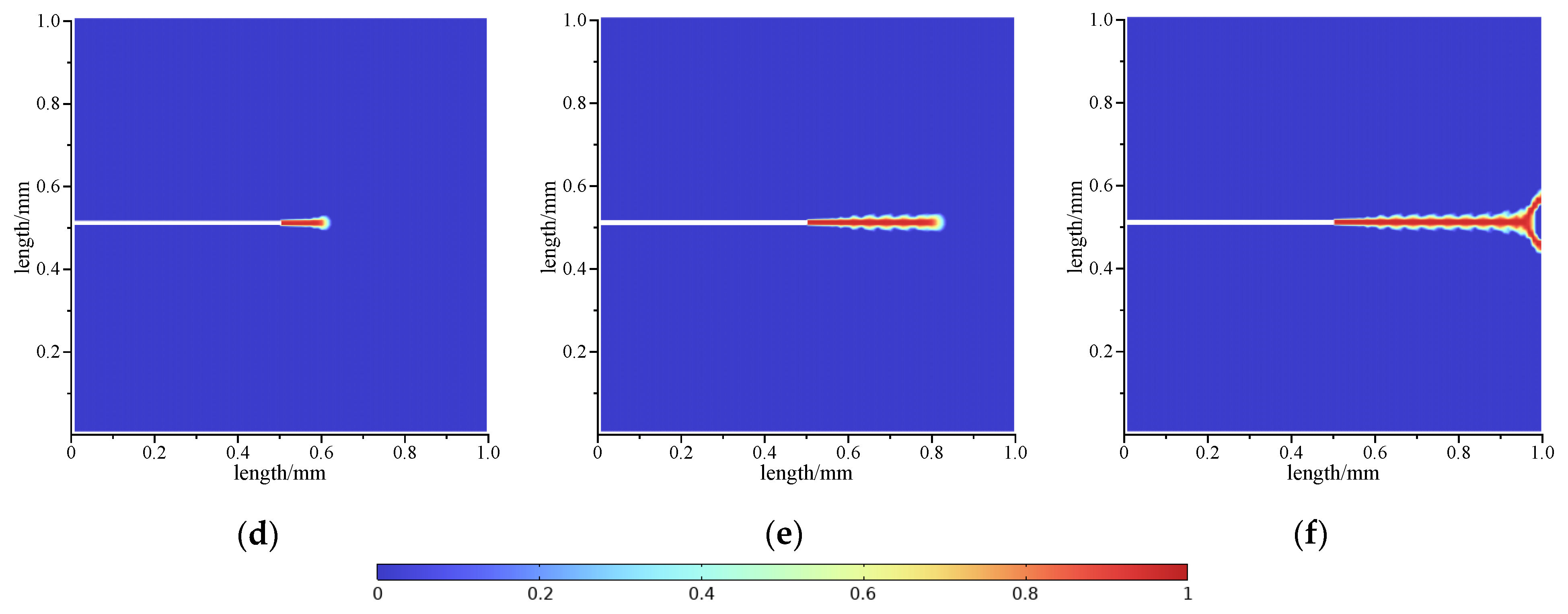
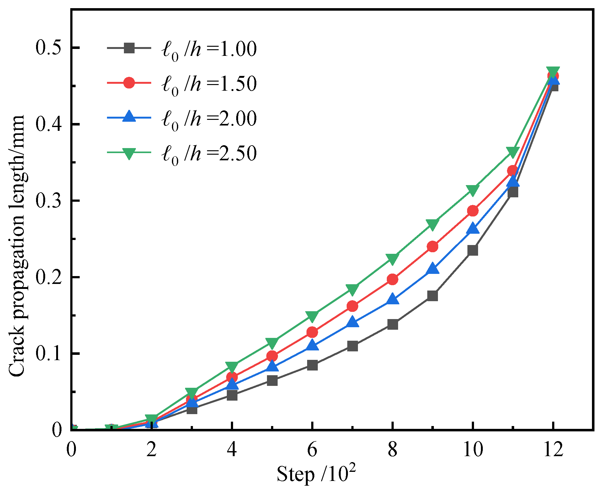
4.1. Single-Edge Notched Tensile Test

This widely adopted phase field validation test involves a 1 mm × 1 mm square plate with a 0.5 mm horizontal notch at the left edge midpoint. Boundary conditions include a fixed bottom edge and vertical displacement loading at the top. The numerical simulations were implemented using the COMSOL Multiphysics platform. A four-node plane stress element mesh is adopted, with refined meshing in the crack propagation region. The minimum element size is h = 0.002 mm, and the total number of elements is 69,682, as shown in Figure 4.
The material parameters adopt the elastic medium data from reference [25]: elastic modulus E = 0.0075 mm , Poisson’s ratio v = 0.3 , critical energy release rate G c = 2.7 kN / m , and characteristic length l 0 = 0.0075 mm (controlling the diffuse width of the crack). The crack propagation paths at different stages are shown in Figure 5, where the crack propagates straight in a direction perpendicular to the loading direction. The color scale is explicitly defined as follows: blue (ϕ = 0) denotes the intact material, blue to red (0 < ϕ < 1) represents progressive damage accumulation, and red (ϕ = 1) indicates complete fracture.
In the single-edge notched tensile test simulation, the phase field variable evolution captures the crack initiation and progressive propagation process. Crack nucleation initiates at the notch tip, followed by linear propagation perpendicular to the loading axis. The crack trajectories remain smooth and singular across loading steps, exhibiting gradual extension without bifurcation or diffuse crack patterns. This linear propagation behavior persists throughout the entire process, demonstrating excellent agreement with dynamic damage evolution characteristics reported by Zhang et al. [32] and Liu et al. [33]. These consistencies validate the accuracy and reliability of the proposed numerical methodology.
To investigate the numerical stability of the phase field method, the single-edge notched tensile model was discretized using four meshes with varying refinement levels. With the phase field characteristic length fixed at l 0 = 0.0075 mm , convergence was assessed by controlling the l 0 / h ratios (1.25, 1.5, 2, and 2.5). Figure 6 depicts crack propagation length versus computational steps for different mesh refinements. Initially, crack extension curves diverge due to mesh sensitivity; however, as computational steps progress, the curves converge, demonstrating diminished mesh dependence post-refinement. These results confirm that the phase field method produces stable numerical solutions with reduced mesh sensitivity under appropriate refinement, validating its numerical robustness in the proposed framework.

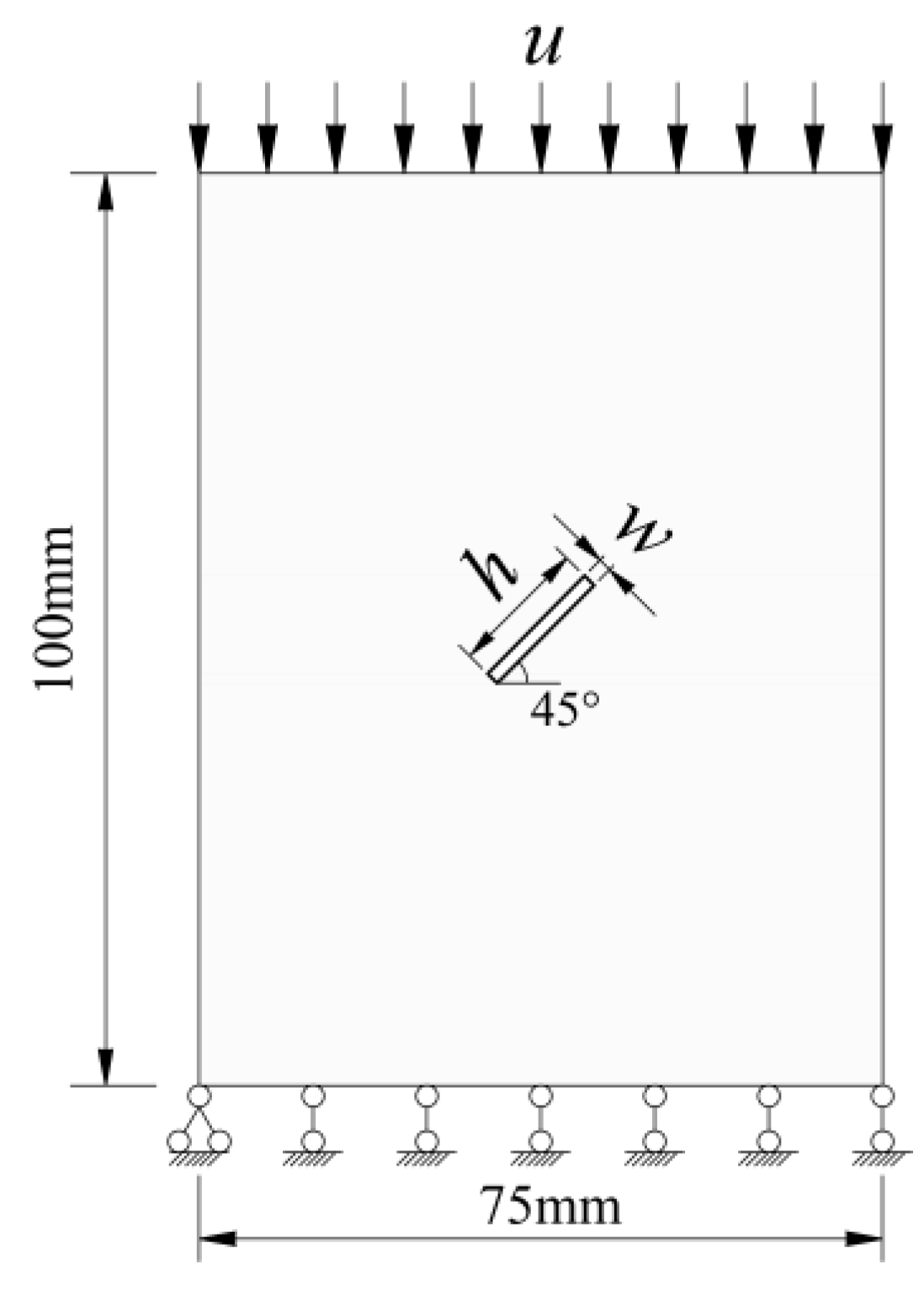
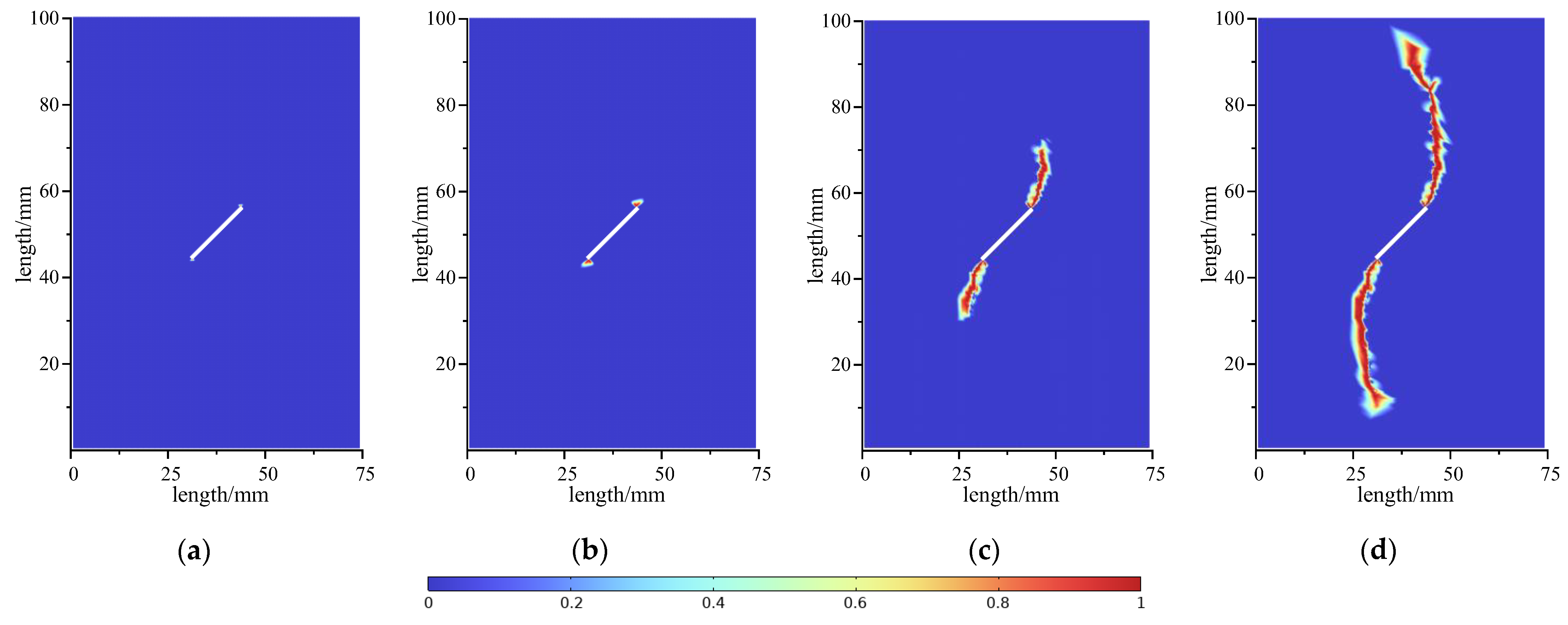
4.2. Uniaxial Compression Test on Rock with a Prefabricated Crack

To simulate and study the crack propagation law of rock under uniaxial compression, a 2D numerical model of a rock square plate with a single prefabricated crack is constructed, as shown in Figure 7. The simulation adopts the plane strain assumption. The model has dimensions of 75 mm × 100 mm, a thickness of 1 mm, and a prefabricated crack at the center with an angle of 45 degrees to the horizontal line, a crack length of h = 20.00 mm, and a width of w = 2.00 mm.
Material parameters are set according to reference [24], and the specific values are shown in Table 1.
The model’s bottom boundary is constrained in the y-direction, while quasi-static displacement loading is prescribed vertically downward at the top boundary with a constant displacement rate of 2 × 10⁻⁴ mm/step. Simulations were performed using custom FE code developed on the COMSOL Multiphysics platform, employing a hybrid meshing strategy that combines quadrilateral elements with triangular elements for local refinement. Mesh size transitions from 0.25 mm near the crack to 0.5 mm at the specimen boundaries. Boundary conditions include normal constraint on the bottom edge; horizontal constraint at the bottom-left node; and displacement-controlled loading at the top. Figure 8 presents the simulation results.
Figure 8 illustrates the phase field simulation results of the uniaxial compression test on prefabricated crack rock, capturing the progressive failure process from crack initiation to macroscopic fracture. During initial loading, the material remains in the elastic stage with no crack propagation. As loading progresses, stress concentration at the crack tip induces localized damage, manifesting as wing cracks propagating perpendicular to the prefabricated crack surface under tensile dominance. With further loading, shear stress accumulation triggers tensile-shear, resulting in through-going fracture surfaces and approaching macroscopic failure. These results align closely with numerical findings from Xiang et al. [12] and Liu et al. [14], confirming the model’s capability to replicate realistic fracture mechanics.
As shown in Figure 9, the load–displacement curve of the uniaxial compression test on rock with prefabricated cracks is presented, where the load represents the vertical load on the model. As displacement gradually increases, the load grows linearly, indicating the elastic deformation stage. When displacement reaches a certain value, cracks initiate, and the load reaches the ultimate bearing capacity, followed by a sharp drop until complete fracture. The phase field method’s load–displacement curve closely matches the existing method [14] in peak load and overall trend. In the elastic stage (0–2.0 mm displacement), both have a slope of 3.0 kN/mm (error < 5%, R2 > 0.99), confirming consistent elastic response. At peak load, this method yields 8.5 kN (2.2 mm) vs. 8.4 kN (2.3 mm) for the existing method (1.2% relative error), validating the accuracy and reliability of simulating uniaxial tensile fracture mechanics.
The simulation results capture the dynamic evolution of the phase field variable ϕ during crack initiation, propagation, and penetration, demonstrating that the phase field model effectively resolves crack growth characteristics in the complex failure process of prefabricated-crack rock. This framework reveals the failure mechanisms of stress concentration, energy release, and progressive damage accumulation under uniaxial compression. Consistent with theoretical failure laws for compressed rock containing prefabricated cracks, these results validate the efficacy of the proposed phase field model in simulating rock failure processes.

5. Discussion

The proposed elastoplastic phase field model offers a novel framework for simulating rock failure under compressive-shear conditions by explicitly coupling plastic deformation with crack evolution. This study bridges critical gaps between classical plasticity theory and phase field fracture mechanics, providing a more realistic description of energy dissipation mechanisms and failure modes in rock engineering applications. While the model demonstrates significant advancements in capturing elastoplastic damage and crack propagation, its assumptions, limitations, and broader implications must be carefully contextualized within both theoretical and practical domains.
(1)
Advantages and Contributions: The model’s primary strength lies in its ability to overcome the limitations of purely elastic phase field approaches. Traditional models often neglect plastic deformation mechanisms such as shear band localization and residual strength, leading to overly brittle predictions. By integrating plastic strain energy and non-associated flow rules, this work quantifies the reduction in crack propagation resistance caused by plastic slip, enabling a seamless transition from elastic loading to plastic damage accumulation and unstable fracture. Numerical validation through single-edge notch tension and uniaxial compression tests confirms the model’s accuracy, with load–displacement curves exhibiting less than 5% error in elastic stiffness and a 1.2% deviation in peak load compared to experimental benchmarks. These results highlight its potential for predicting residual strength in underground engineering structures, where stress redistribution and long-term stability are paramount.
(2)
However, the model’s reliance on small-deformation theory and isotropic hardening assumptions introduces constraints. Scenarios involving large rotations, such as shear band widening or rockbursts, may require extensions to finite-deformation frameworks to account for geometric nonlinearity. Additionally, the omission of crack interaction mechanisms—such as coalescence or branching—limits its applicability to multi-fracture systems. Furthermore, while key parameters (e.g., critical energy release rates, regularization length scale, and residual strength coefficient) are calibrated through benchmark tests, their sensitivity to crack propagation behavior and energy dissipation remains to be systematically quantified. A comprehensive parametric sensitivity analysis would refine calibration protocols for heterogeneous rock masses, though such an exploration is deferred to future work to maintain focus on the foundational coupling framework proposed here.
(3)
Comparison with Existing Studies: When compared to existing studies, the proposed model distinguishes itself through its explicit integration of plasticity and fracture mechanics. Prior hydromechanical phase field models, such as those by Wang et al. [15] and Liu et al. [16], omitted plastic energy dissipation, while cohesive zone approaches employed by Liu et al. [14] relied on predefined crack paths. In contrast, this work eliminates such constraints, enabling autonomous crack initiation and propagation through a unified energy functional. This theoretical innovation not only enhances computational flexibility but also provides a more holistic representation of rock behavior under compressive-shear loading, as evidenced by its alignment with classical experimental observations.
(4)
Future Directions: Future research should focus on expanding the model’s scope to address multifield coupling and dynamic loading scenarios. Incorporating thermo-hydro-mechanical (THM) interactions would improve predictions for saturated or thermally altered rock masses, where pore pressure and temperature gradients significantly influence fracture behavior. Extending the framework to dynamic regimes, such as blasting or seismic loading, could unravel crack propagation mechanisms under rapid stress changes. Preliminary studies on cyclic loading and crack branching already show promise, with results correlating well with experimental acoustic emission data. Furthermore, integrating machine learning techniques could streamline parameter inversion processes, particularly for heterogeneous formations where empirical calibration is impractical. These advancements would transform the model into a versatile tool for both academic research and industrial applications, ultimately advancing the safety and efficiency of rock engineering projects.

6. Conclusions and Prospects

(1)
This study develops an elastoplastic phase field fracture model, incorporating plastic deformation mechanisms and overcoming the limitations of conventional elastic models under compressive-shear conditions. By integrating plastic strain energy and non-associated flow rules, the framework couples plasticity with phase field damage evolution, explicitly quantifying how plastic slip and shear band formation regulate crack driving forces and propagation paths. The model successfully simulates complete energy evolution processes—from elastic loading to plastic damage accumulation and unstable fracture—providing a novel theoretical tool for analyzing mesoscale rock failure mechanisms under compressive-shear stresses.
(2)
The numerical implementation leverages finite element discretization and nonlinear solvers, validating the model’s capability to simulate complex crack propagation. The coupled interpolation of displacement and phase fields, staggered algorithms, and Newton–Raphson iterations address elastoplastic coupling nonlinearities. Benchmark tests—including single-edge notched tension and prefabricated-crack compression—demonstrate the accurate capture of crack initiation dynamics, wing crack propagation, and through-going failure. Specifically, in the elastic deformation stage, the load–displacement curve exhibits a slope error < 5% and a correlation coefficient R2 > 0.99. At the peak load, the relative error between this model and data from the literature is only 1.2%. These quantitative results further validate the reliability of this model.
(3)
The findings offer practical engineering relevance for hydraulic fracturing and underground energy storage applications. By quantifying plastic deformation’s impact on crack driving forces, the model enables reliable residual strength predictions, reducing dependency on costly physical tests for the long-term stability assessments of underground structures. Additionally, full-process energy evolution simulations support parameter inversion in real-time monitoring systems, enhancing safety and cost-efficiency in rock engineering projects.
(4)
Future research should focus on multifield coupling extensions and parameter optimization under dynamic loads. Integrating thermal, hydraulic, and mechanical (THM) couplings into phase field frameworks will advance the modeling of complex geological conditions. Developing data-driven parameter inversion methods and incorporating non-local plasticity theory to refine shear band width simulations are critical directions for advancing rock fracture mechanics research.

Author Contributions

Methodology, G.Q.; software, G.Q. and B.W.; investigation, G.Q.; writing—original draft preparation, G.Q.; writing—review and editing, J.Z. and B.W.; supervision, J.Z.; All authors have read and agreed to the published version of the manuscript.

Funding

This research was funded by the National Natural Science Foundation of China (grant number 52404144) and the Natural Science Basic Research Program of Shaanxi (grant number 2024JC-YBQN-0594).

Institutional Review Board Statement

Not applicable.

Informed Consent Statement

Not applicable.

Data Availability Statement

The relevant data in this manuscript were obtained from field measurements and tests, which are real and effective.

Conflicts of Interest

The authors declare no conflicts of interest.

References

  1. Chen, B.; Barboza, B.R.; Sun, Y.; Bai, J.; Thomas, H.R.; Dutko, M.; Cottrell, M.; Li, C. A review of hydraulic fracturing simulation. Arch. Comput. Methods Eng. 2022, 29, 1–58. [Google Scholar] [CrossRef]
  2. Ismail, A.; Azadbakht, S. A comprehensive review of numerical simulation methods for hydraulic fracturing. Int. J. Numer. Anal. Methods Geomech. 2024, 48, 1433–1459. [Google Scholar] [CrossRef]
  3. Liu, X.; Hao, Z.; Liu, S.; Zhang, P.; Pan, Y. Study of fracture behavior in three-dimensional Brazilian disk based on phase field method. J. Dalian Univ. Technol. 2025, 65, 181–190. [Google Scholar]
  4. Ying, Y.; Huang, W.; Ma, Y.; Peng, F. Fracture behavior of periodic porous structures by phase field method. Chin. J. Theor. Appl. Mech. 2022, 54, 3430–3443. [Google Scholar]
  5. Xu, Q.; Wang, S.; Chen, J.; Wang, M.; Liu, J. Polygon finite element simulation based on unified phase field theory. Yangtze River 2025, 56, 216–223+239. [Google Scholar]
  6. Khisamitov, I.; Meschke, G. Variational interface element model for 2d and 3d hydraulic fracturing simulations. Comput. Methods Appl. Mech. Eng. 2021, 373, 113450. [Google Scholar] [CrossRef]
  7. Yoshioka, K.; Naumov, D.; Kolditz, O. On crack opening computation in variational phase-field models for fracture. Comput. Methods Appl. Mech. Eng. 2020, 369, 113210. [Google Scholar] [CrossRef]
  8. Long, X.; Zhu, J.; Su, Y.; Jiang, X.; Jin, P. Analysis of crack evolution and mechanical properties degradation of polymer bonded explosives based on phase-field fracture. Chin. J. Comput. Mech. 2024, 41, 682–688. [Google Scholar]
  9. Francfort, G.A.; Marigo, J.-J. Revisiting brittle fracture as an energy minimization problem. J. Mech. Phys. Solids 1998, 46, 1319–1342. [Google Scholar] [CrossRef]
  10. Wu, J. On the unified phase-field theory for damage and failure in solids and structures: Theoretical and numerical aspects. Chin. J. Theor. Appl. Mech. 2021, 53, 301–329. [Google Scholar]
  11. Zhang, W.; Shen, Z.; Xu, L.; Zhang, H.; Gan, L.; Li, G. A phase-field fracture model for brittle materials based on COMSOL. Chin. J. Comput. Mech. 2023, 40, 273–280. [Google Scholar]
  12. Xiang, F.; Zhao, C.; Xing, J. Research on crack propagation and damage evolution of rock based on the unified phase-field theory. Chin. J. Rock Mech. Eng. 2023, 42 (Suppl. S1), 3519–3528. [Google Scholar]
  13. Sun, G.; Yi, Q.; Yao, Y.; Shang, H.; Ji, W. Study on the potential instability patterns of tunnel type underground cavernsfor compressed air energy storage. Chin. J. Rock Mech. Eng. 2024, 43, 41–49. [Google Scholar]
  14. Liu, S.; Wang, W.; Cao, Y.; Zhu, Q.; Shao, J. Study on the elastoplastic damage model for rock based on the phase-fieldmethod and its numerical implementation. Chin. J. Rock Mech. Eng. 2023, 42, 896–905. [Google Scholar]
  15. Wang, Y.; Wang, Y.; Liu, S.; Kou, M. Phase field modelling of the hydro-mechanical coupling failure mechanisms of fissured rock masses. J. Civ. Environ. Eng. 2024, 46, 211–220. [Google Scholar]
  16. Liu, J.; Xue, Y.; Gao, F.; Teng, T.; Liang, X. Propagation of hydraulic fractures in bedded shale based on phase-field method. Chin. J. Geotech. Eng. 2022, 44, 464–473. [Google Scholar]
  17. Yi, L.; Li, X.; Yang, Z.; Yang, C. Phase field modeling of hydraulic fracturing in porous media formation with natural fracture. Eng. Fract. Mech. 2020, 236, 107206. [Google Scholar] [CrossRef]
  18. Yousef, H. A review on phase-field modeling of hydraulic fracturing. Eng. Fract. Mech. 2021, 253, 107881. [Google Scholar]
  19. Zhou, S.; Zhuang, X.; Rabczuk, T. Phase field method for quasi-static hydro-fracture in porous media under stress boundary condition considering the effect of initial stress field. Theor. Appl. Fract. Mech. 2020, 107, 102523. [Google Scholar] [CrossRef]
  20. Kar, S.; Chaudhuri, A.; Singh, A.; Pal, S. Phase field method to model hydraulic fracturing in saturated porous reservoir with natural fractures. Eng. Fract. Mech. 2023, 286, 109289. [Google Scholar] [CrossRef]
  21. Lü, M.; Zhu, Z.; Zhou, L.; Ge, X. Numerical simulation of hydraulic fracture propagation in rock masses with pre-existing double fractures using the phase field method. Rock Soil Mech. 2024, 45, 1850–1862. [Google Scholar] [CrossRef]
  22. Lü, Z.; Wu, M.; Duan, J.; Huang, Y. Phase-field modeling of frost propagation of cracks for rock mass under frost action. Chin. J. Geotech. Eng. 2023, 45, 2258–2267. [Google Scholar]
  23. Bourdin, B.; Francfort, G.A.; Marigo, J.J. Numerical experiments in revisited brittle fracture. J. Mech. Phys. Solids 2000, 48, 797–826. [Google Scholar] [CrossRef]
  24. Wang, S.; Yang, S.; Tian, W.; Huang, Y. Research on phase-field simulation method of crack propagation of rockwith pre-existing fissures. Chin. J. Rock Mech. Eng. 2023, 42, 365–377. [Google Scholar]
  25. Wang, F. Unified fracture phase-field method and determination of crack width for brittle materials. Eng. Mech. 2024, 41, 1–8. [Google Scholar] [CrossRef]
  26. Lu, Q.; Zhang, H.; Guo, J.; Ren, Y.; He, L.; Yuan, C. Status and prospect of hydraulic fracture propagation simulation based on phase field method. Nat. Gas Ind. 2023, 43, 59–68. [Google Scholar]
  27. Cao, Y.; Sun, K.; Zhu, S.; Huang, J.; Ma, L. Elastoplastic fracture simulation of plate with hole based on phase field method. Ordnance Mater. Sci. Eng. 2021, 44, 39–44. [Google Scholar]
  28. Zhao, C.; Rao, Q.; Yi, W.; Luo, S. A study on multiple-crack propagation of brittle rock based onmixed-mode phase field model. J. Railw. Sci. Eng. 2023, 20, 565–575. [Google Scholar]
  29. Qiu, S.; Duan, Q.; Shao, Y.; Yao, W. Consistent element-free Galerkin method for phase-field model of brittle fracture in elasto-plastic solids. Chin. J. Comput. Mech. 2023, 40, 60–65. [Google Scholar]
  30. Wang, H.; Wu, G. Study on mechanical properties of steel fiber reinforced concrete interface transition zone based on unified phase-field theory and cohesive zone model. J. Hebei Univ. Sci. Technol. 2023, 44, 112–122. [Google Scholar]
  31. Yuan, J.; Chen, C. Brittle Fracture Analysis of One-dimensional Pull Rod Based on Phase-field Model. J. Hunan Univ. Nat. Sci. 2021, 48, 53–58. [Google Scholar]
  32. Zhang, W.; Zhuang, M.; Zhu, X.; Shen, W.; Chen, M. A Novel Degradation Function of the Phase Field Method for Quasi-brittle Fracture. China Rural. Water Hydropower 2022, 2022, 201–207. [Google Scholar]
  33. Liu, G.; Li, Q.; Zuo, Z. Implementation of a staggered algorithm for a phase field model in ABAQUS. Chin. J. Rock Mech. Eng. 2016, 35, 1019–1030. [Google Scholar]
  34. Li, M.; Li, S.; Zuo, J.; Wang, Z.; Peng, L.; Xue, X. Numerical simulation of three-point bending failure behavior of basalt based on phase field method. Sci. Technol. Eng. 2022, 22, 13441–13449. [Google Scholar]
  35. Liu, G.; Li, Q.; Liang, G. A phase-field description of dynamic hydraulic fracturing. Chin. J. Rock Mech. Eng. 2017, 36, 1400–1412. [Google Scholar]
  36. Zhang, Z.; Hao, L. Application of X-FEM in a phase-field model for crack propagation. Acta Aeronaut. Astronaut. Sin. 2022, 43, 475–485. [Google Scholar]
Figure 1. Phase field crack characterization method. (a) Schematic of phase field crack characterization; (b) approximate characterization of crack topology.
Applsci 15 06206 g001
Figure 2. Flowchart of staggered solution algorithm.
Applsci 15 06206 g002
Figure 3. Nonlinear iterative solution flowchart.
Applsci 15 06206 g003
Figure 4. Single-edge notched tensile test model.
Applsci 15 06206 g004
Figure 5. Single-edge notched tensile test phase field simulation results: (a) 200 steps; (b) 400 steps; (c) 600 steps; (d) 800 steps; (e) 1000 steps; (f) 1200 steps.
Applsci 15 06206 g005aApplsci 15 06206 g005b
Figure 6. Crack propagation behavior under different mesh sizes.
Applsci 15 06206 g006
Figure 7. Uniaxial compression test model for rock with a prefabricated crack.
Applsci 15 06206 g007
Figure 8. Uniaxial compression test phase field simulation results for rock with a prefabricated crack: (a) 250 steps; (b) 500 steps; (c) 750 steps; (d) 1000 steps.
Applsci 15 06206 g008
Figure 9. Load–displacement curve of uniaxial compression test for rock with prefabricated cracks.
Applsci 15 06206 g009
Table 1. Material parameters and their values used in the simulation.
Symbol of Material ParameterName of Material ParameterValuesUnit
E elastic modulus 32.15 GPa
v Poisson’s ratio 0.3
φ angle of internal friction 38.8 °
c cohesion 18.5
G cI + critical energy release rate for tensile fracture 11.0 J / m 2
G cII + critical energy release rate for tension–shear fracture 50   G cI +
G c critical energy release rate for compression–shear fracture 27   G cII +
G pD critical energy release rate for plastic damage 10   G cI +
K p plastic bulk modulus 10.0 GPa
μ p plastic shear modulus 5.0 GPa
α material parameter 0.65
k hardening parameter 0.5
l 0 scale parameter 0.5 mm
Disclaimer/Publisher’s Note: The statements, opinions and data contained in all publications are solely those of the individual author(s) and contributor(s) and not of MDPI and/or the editor(s). MDPI and/or the editor(s) disclaim responsibility for any injury to people or property resulting from any ideas, methods, instructions or products referred to in the content.

