Abstract
Particle radiotherapy based on the medical accelerator is emerging as a major treatment for cancer. To enhance the clinical flexibility of particle radiotherapy and further promote the use of medical accelerators, the Shanghai Institute of Applied Physics (SINAP) has presented a new linear accelerator plan for medical application. The new plan utilizes a 200 MHz Radio Frequency Quadrupole (RFQ) as the injector. The RFQ is designed to accelerate ions with charge-to-mass ratios of 1/3 to 1/2 from 8 keV/u to 750 keV/u. For the beam dynamics design, a new design strategy is presented to enhance the suppression of space charge effects and improve beam capture efficiency by optimizing the modulation, synchronous phase, and focusing strength. The simulation results demonstrate that the multi-ion RFQ can operate at a maximum beam current of 3.2 mA while maintaining a transmission efficiency above 95% with a compact length of 2.5 m. Multi-particle simulations confirm the high reliability of the design. Additionally, input and mechanical error analyses evaluate the RFQ’s tolerance and stability. The research results demonstrate the feasibility of a compact, high-efficiency RFQ for multi-ion acceleration in medical applications, contributing to the advancement of particle therapy.
1. Introduction
Particle radiotherapy is an advanced radiotherapy technique that utilizes high-energy particles, such as protons and carbon ions, to destroy tumour cells [1]. By leveraging characteristics of different charged particles, such as the Bragg peak and relative biological effectiveness (RBE), personalized treatment plans can be tailored [2]. However, most of the existing medical accelerator systems are designed for single-ion acceleration [3,4,5,6], which makes it difficult to cover all clinical treatment scenarios, restricting treatment flexibility and increasing treatment costs. Therefore, there is a need to design a medical accelerator capable of accelerating a variety of ions, which can flexibly adjust the treatment plan according to different clinical needs, so as to achieve personalized treatment [7,8,9].
The RFQ is a linear accelerator that provides both transverse focusing and longitudinal bunching, offering significant advantages in accelerating beams with low velocities [10]. Many medical accelerators have used RFQ as injectors for the initial acceleration and bunching of particle beams, ensuring high-quality beam injection into downstream accelerators [11,12,13,14]. Thus, one of the key steps in developing a medical accelerator for multi-ion radiotherapy is designing a multi-ion-compatible RFQ [15,16,17].
In the study of RFQ beam dynamics, several innovative strategies have been developed to improve beam quality, transmission efficiency, and structural compactness. For example, fast-bunching designs [18] shorten the bunching section to reduce overall RFQ length and boost transmission efficiency; truncated-vane modulation introduces regions of zero longitudinal electric field to lower longitudinal emittance [19]; high-frequency compact [20,21] significantly reduce both RFQ length and RF power consumption; and optimized radial-matching sections adjust potential-function boundary conditions to enhance transmission stability [22]. However, these methods are typically designed for a specific ion species or charge-to-mass ratio and do not consider performance when accelerating additional or different ions. Consequently, in multi-ion radiotherapy or other applications requiring the acceleration of multiple ion species, a single RFQ often cannot simultaneously account for the space charge effects and bunching characteristics of different ions. As a result, a separate RFQ accelerator is typically required for each species [23,24,25], leading to higher costs or greater design complexity.
To address this issue, a new beam dynamics design strategy focusing on multi-ion acceleration within the same RFQ is proposed in this study. Its main contributions are as follows:
- Achieving Multi-Ion Compatibility via Dynamic Focus–Defocus Control: By adjusting the focusing strength to achieve a dynamic balance with the defocusing strength, the efficient transmission of multiple ion species within the same RFQ is improved.
- Quantification and Optimization of Stable Longitudinal Phase Space Area: A parameter is introduced to characterize the stable longitudinal phase space area and optimized to maximize beam capture efficiency.
- Error Tolerance Analysis: Using comprehensive error studies, acceptable tolerances for input-beam errors and mechanical fabrication errors are determined, and practical guidelines for RFQ construction and operation are provided.
The structure of this paper is as follows: Section 2 introduces the basic principles of the RFQ. Section 3 describes the beam dynamics design strategy along with simulation results that validate the effectiveness of the proposed method. Section 4 analyzes the operational and manufacturing error tolerances of the RFQ. Finally, Section 5 presents the conclusions.
2. Basic Principles of the RFQ
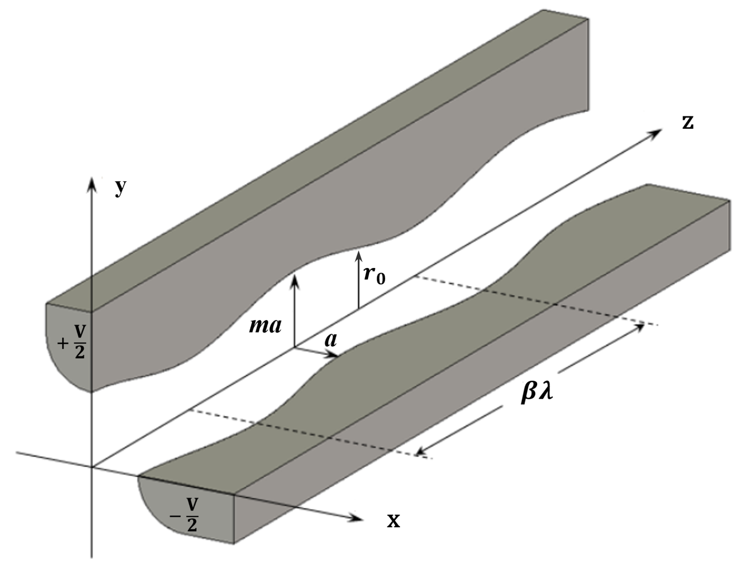
In the RFQ, the beam is focused transversely by RF electric quadrupole fields and accelerated by longitudinal RF electric fields. In the RFQ, the formation of the electric field depends on the electrode geometry. The schematic structure of the RFQ is illustrated in Figure 1, where a is the minimum radial aperture, m is the modulation parameter, is the maximum aperture, is the average aperture, V is the voltage, is the modulation period, where represents the relativistic speed, and is the RF wavelength. Each modulation period includes two cells, and the length of each cell is . By applying voltages of to adjacent electrodes, an RF electric quadrupole field is generated, providing transverse focusing for the beam. In addition, a longitudinal accelerating field is produced along the beam axis by introducing periodic modulation of the electrode geometry, enabling efficient acceleration.

Figure 1.
Schematic Diagram of the Modulated Electrodes in an RFQ.
To characterize the focusing and accelerating properties of an RFQ quantitatively, several key performance parameters are defined. The focusing strength factor B is defined by:
where q is the charge, is the rest mass, c is the speed of light, and f is the frequency.
The defocusing factor is defined by:
where is the synchronous phase, is the Lorentz factor, and A is the acceleration efficiency, which is defined as:
where m is the modulation parameter, is the modified Bessel function of the first kind, k is the wave number, given by .
For the RFQ, an excessively high surface electric field can lead to breakdown and discharge phenomena, potentially compromising the stable operation of the RFQ cavity. The Kilpatrick factor is commonly used as an empirical criterion to evaluate the risk of RF breakdown [26]. It is defined as follows:
where is the maximum surface field, is the Kilpatrick limit, which is defined as:
3. Beam Dynamics Design
3.1. Design Considerations
This RFQ is designed to accelerate ions with charge-to-mass ratios ranging from 1/3 to 1/2, primarily C and He, focusing on the ion species commonly used in current and next-generation medical radiotherapy [27,28]. The design parameters of the RFQ should fully take into account the current technological capabilities, as well as the operational requirements of both upstream components (ion source and Low Energy Beam Transport, LEBT) and downstream components (Drift Tube Linac, DTL).
- Beam current: The selection of RFQ beam current is closely related to the dose rate required for clinical particle therapy. Considering the clinical dose rate requirements [29,30] and referencing the beam current settings of the existing medical RFQ accelerator [31,32], the beam current is set to 0.3 mA for C and 1 mA for He.
- Operating frequency: In order to maintain sufficient focusing strength when increasing the RFQ operating frequency, the average aperture must be reduced accordingly. If the average aperture is too small, it is not conducive to beam transmission. On the other hand, if the aperture is not reduced, the voltage needs to be increased, which increases the risk of RF breakdown. Considering the size of the cavity and the frequency of commonly available power sources, the operating frequency of the RFQ is set to 200 MHz.
- Injection energy: The input energy should be consistent with the extraction voltage of the ion source. In addition, it affects the design of the LEBT. If the input energy is too low, space charge effects will be intensified, placing stricter requirements on the vacuum level and magnetic focusing system of the LEBT. Conversely, an excessively high injection energy may lead to an increase in the length of the LEBT. Considering prior experience with stable RFQ operation and established design practices [11,33], the injection energy is ultimately set to 8 keV/u.
- Output energy: The output energy of the RFQ not only affects its own length but is also directly related to the design of the subsequent DTL. If the output energy is too high, the length of the RFQ will increase significantly, leading to higher manufacturing costs and a larger equipment footprint. In contrast, if the injection energy into the DTL is too low, it may result in an uneven radial electric field distribution within the drift tube, leading to degraded beam quality. Considering both the length of the RFQ and the complexity of the subsequent DTL design, the RFQ output energy is ultimately set to 750 keV/u.
- Input emittance: An excessively large input emittance increases beam loss, while an overly small emittance leads to higher beam density and enhanced space charge effects. Therefore, an appropriate input emittance is essential not only for reducing the probability of beam loss but also for ensuring stable beam transport. Ultimately, the input emittance is set to 0.2 mm·mrad.
- Voltage and Kilpatrick factor: To maintain sufficient focusing strength and accelerating gradient, the inter-vane voltage is selected within the range of 60–80 kV. Simultaneously, the Kilpatrick factor is limited to below 1.8 in order to minimize the risk of RF breakdown within the cavity. This choice aligns with the design practices of many RFQs currently in operation at frequencies close to 200 MHz [31,33,34], where similar voltage ranges and Kilpatrick factors are commonly adopted to ensure reliable and stable operation.
In addition to considering the design parameters, there are several specific operational and performance requirements.
- Multi-ion compatibility: Ions with different charge-to-mass ratios exhibit varying sensitivities to space charge effects. Therefore, when designing an RFQ capable of accelerating multi-ion, one of the primary considerations is the influence of space charge effects. In RFQ beam dynamics design, the ability to suppress space charge effects is typically evaluated by examining the reduction in transmission efficiency as the beam current increases. If the degree of efficiency degradation decreases with increasing beam current, it indicates a stronger capability to mitigate space charge effects. Therefore, it demonstrates better compatibility when the RFQ accelerates ions that are more sensitive to space charge effects. Considering the ion species that the RFQ is designed to accommodate and their sensitivity to space charge effects, the transmission efficiency for 1 mA He should be no less than 95%.
- Compact structure: During the design of medical accelerators, compactness is one of the key priorities. A compact structure not only reduces manufacturing and installation costs but also reduces space requirements, making it convenient to use in medical environments. In this study, to balance cost and space constraints, the RFQ length is limited to less than 2.8 m.
- Operational stability: Due to the limitations of actual experimental conditions, the operating state of each accelerator is often not completely ideal. Therefore, it is crucial for the RFQ to have sufficient error tolerance. Considering input beam errors, the RFQ should exhibit adequate tolerance to ensure that the beam transmission efficiency remains above 95%. Under the influence of mechanical manufacturing errors, the emittance growth of the RFQ is required to be kept below 5%, and the extra beam loss should be less than 10%.
Finally, the requirements for the multi-ion RFQ are summarized in Table 1.

Table 1.
Design requirements of the multi-ion RFQ.
3.2. Design Strategy
3.2.1. General Design
The beam dynamics design of the RFQ was performed using PARMTEQM [35], which includes collective effects in its simulation results, especially space charge effects. The initial design followed the general design strategy [36], which is one of the most widely used in RFQ design [37,38,39,40]. This strategy also often serves as a starting point and reference for many studies involving beam dynamics design and optimization [18,21,41,42,43]. Therefore, it is suitable to serve as a reference for the first-stage design of the multi-ion RFQ. In the general design, the RFQ is divided into four sections: the radial matching section (RM), the shaper section (SH), the gentle buncher section (GB), and the accelerator section (AC). In the RM section, the beam is completely matched. In the SH section, a longitudinal phase-stable region is formed to capture the beam. In the GB section, a gentle and adiabatic bunching process is used to compress the beam and suppress space charge effects by maintaining a constant focusing strength factor and constant voltage. In the AC section, the beam is rapidly accelerated to its final output energy.
The design parameters are illustrated in Table 2. In this design, the constant focusing strength factor 4.2, the voltage of 70 kV, and the synchronous phase range from to were adopted. The choice of these parameters was based on the operational experience of currently well-performing medical accelerators: the Heavy Ion Medical Machine (HIMM) [18], the Heavy Ion Medical Accelerator in Chiba (HIMAC) [31], and the Heidelberg Ion-Beam Therapy Center (HIT) [44]. The number of particles was set to 10,000 with a 4D water-bag distribution [45]. The beam dynamics simulation results are shown in Figure 2 and Figure 3.
Table 2.
Comparison of parameters between the general design and the new design.
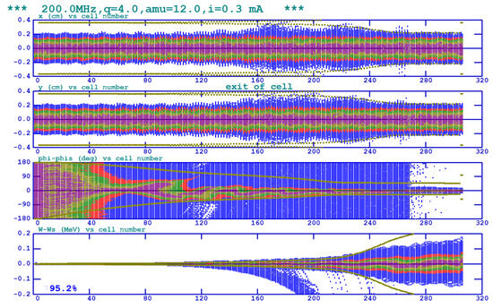
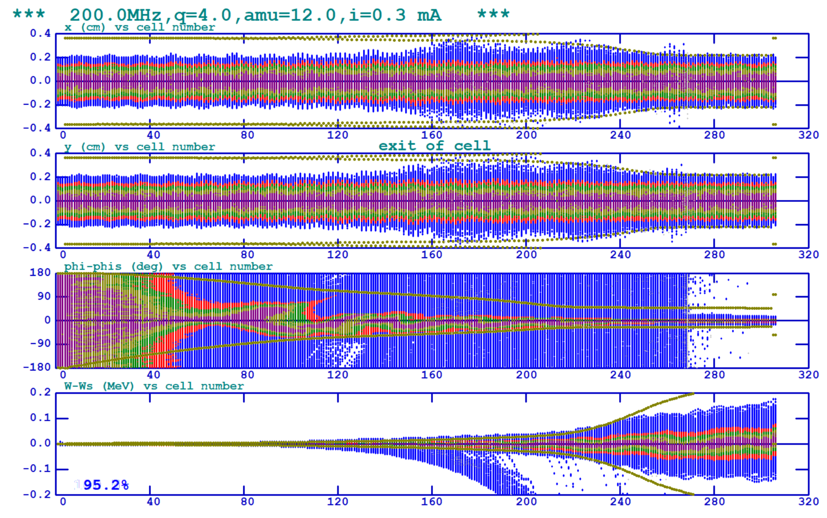
Figure 2.
Beam dynamics simulation results for (general design). Plots from top to bottom show the beam envelope evolution along the RFQ in the x and y planes, and the phase and energy spectra, respectively (color online).
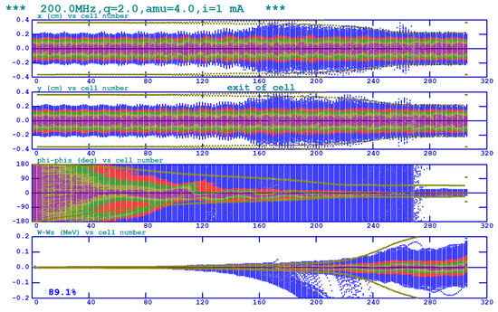
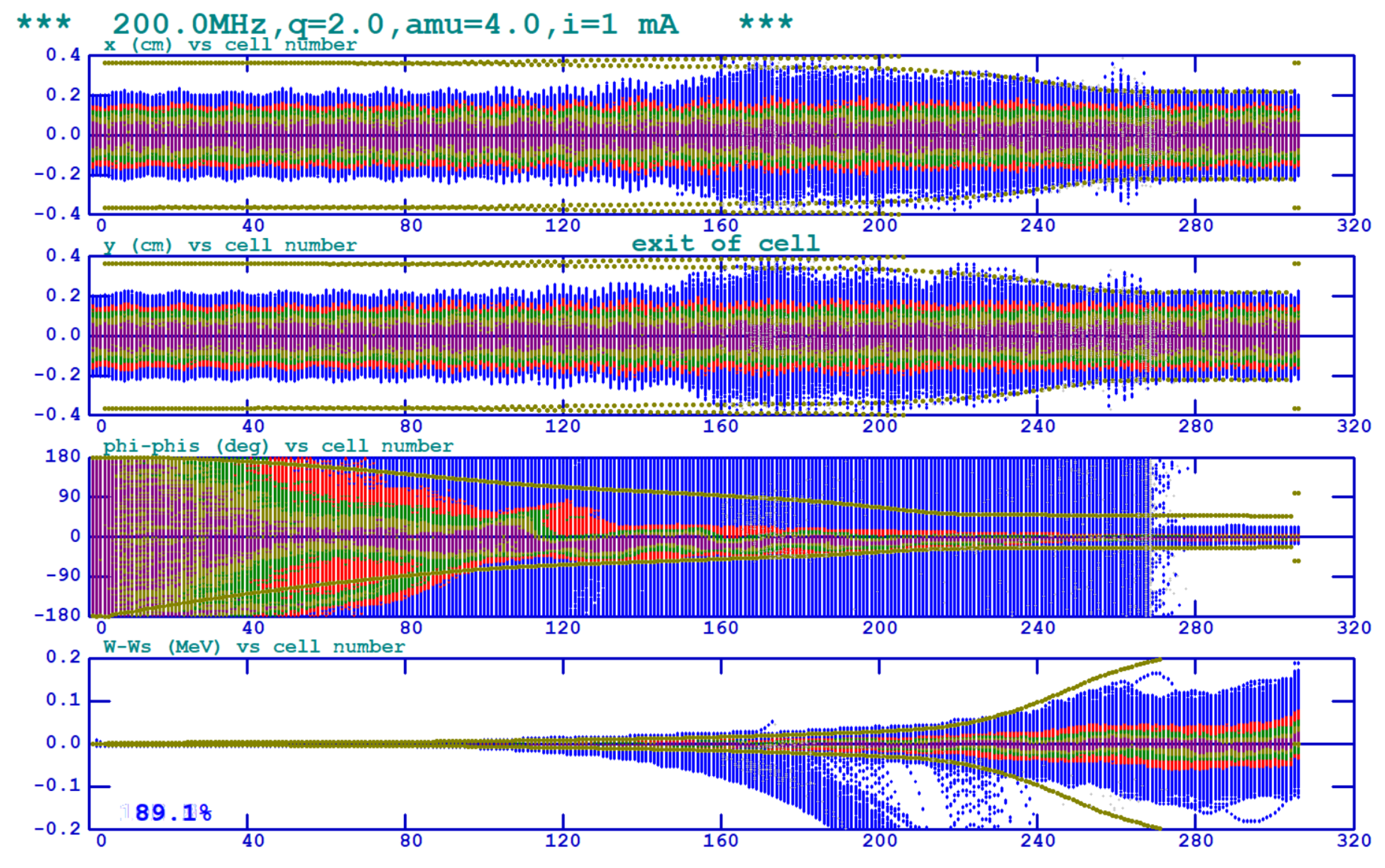
Figure 3.
Beam dynamics simulation results for (general design). Plots from top to bottom show the beam envelope evolution along the RFQ in the x and y planes, and the phase and energy spectra, respectively (color online).
In both figures, the top two plots show the transverse beam envelope changes along the RFQ, illustrating the transverse focusing process. The bottom two plots display the longitudinal beam envelope changes, indicating the phase and energy distributions generated by the design for beam acceleration. The transmission efficiency is 95.2% for 0.3 mA and 89% for 1 mA within the same RFQ. For the length and Kilpatrick factor meet the required specifications. However, several issues were identified in the general design, as listed below:
- For 1 mA , the transmission efficiency falls below the required minimum of 95%.
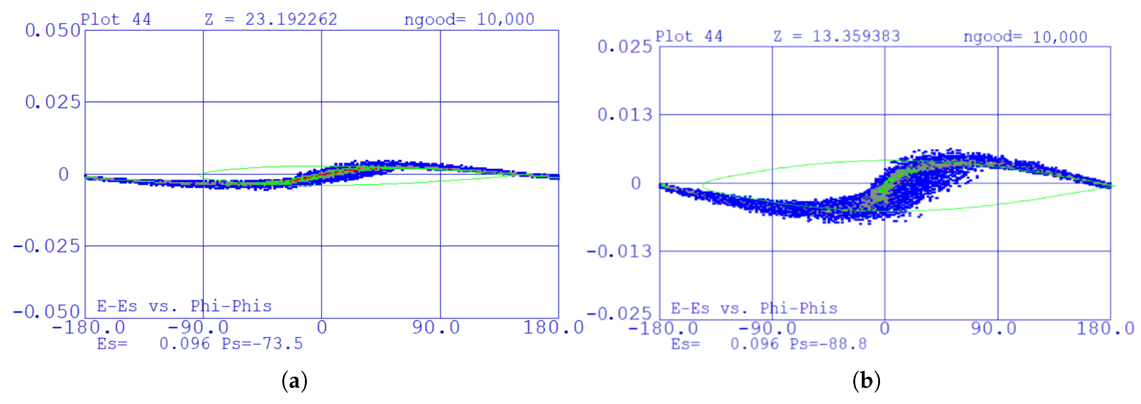
- The beam was not well captured in the shaper section, as observed in Figure 4, resulting in increased longitudinal losses and longitudinal emittance.
- Figure 5 shows the transmission efficiency of the RFQ versus beam current. As the beam current increases to 8 mA, the transmission efficiency decreases from 95.2% to 32%, representing a total reduction of 63.2%. This indicates that the RFQ exhibits high sensitivity to beam current fluctuations and has limited capability in suppressing space charge effects. This limitation becomes especially critical when accelerating different ion species, particularly those that are highly sensitive to space charge effects.
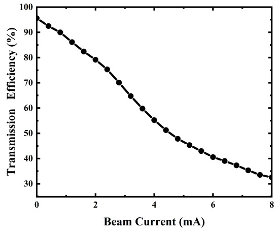 Figure 5. Transmission efficiency of the RFQ versus beam current (General design).
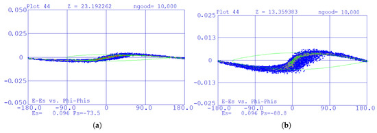
Figure 4.
Beam in shaper section, the area surrounded by the green line represents the area of separatrix. (a) General design. (b) New design.
Figure 4.
Beam in shaper section, the area surrounded by the green line represents the area of separatrix. (a) General design. (b) New design.
In light of the issues identified in the general design, it is necessary to propose a new RFQ design strategy.
3.2.2. New Design
Since the RFQ is designed for multi-ion and medical applications, it requires strong suppression capabilities to space charge effects. In addition to adiabatic bunching, the suppression of space charge effects can still be enhanced by varying the focusing strength factor B across the cells. The B is adjusted by Equations (2) and (6) to achieve a dynamic balance between focusing and defocusing forces, ensuring stable beam transmission.
where n is the cell number along the RFQ, the term is obtained by applying the smooth-approximation formalism [46].
To improve the RFQ’s capture efficiency, a suitable stable area in the longitudinal phase space should be designed. The parameter S [47] represents the area of the separatrix, i.e., the stable area in longitudinal phase space. Adjustments to the stable area are achieved by modifying the modulation parameter and the synchronous phase.
where is the synchronous energy, and is the stable phase zone.
and are the longitudinal and transverse phase advances at zero current. is acceleration term, defined as . Adjustments to the stable area must ensure that to avoid phase advance resonance and resultant extra beam loss.
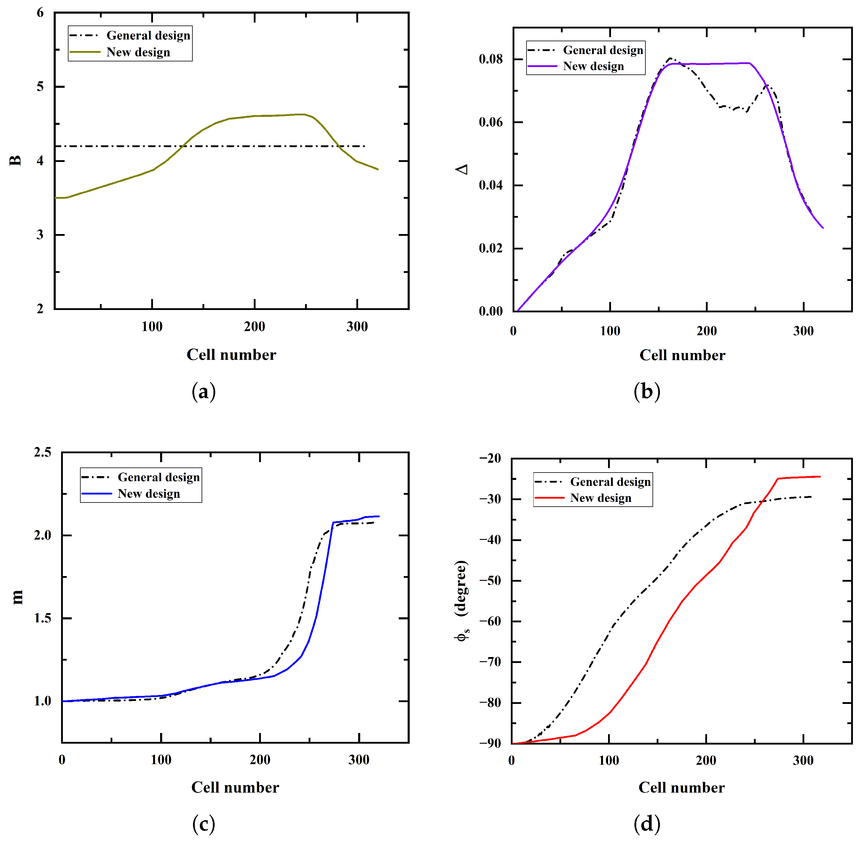
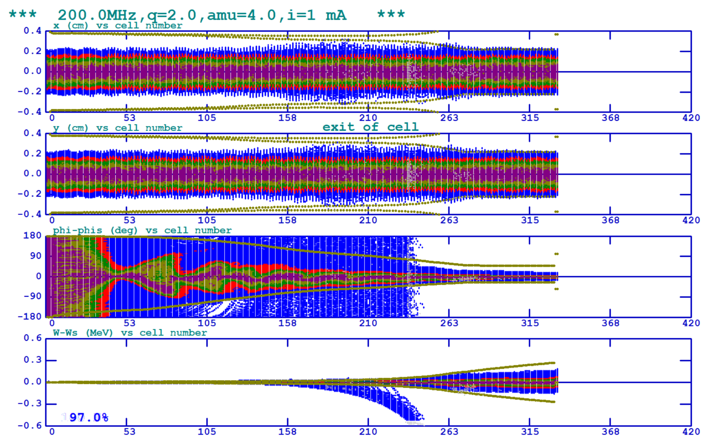
The optimization parameters are shown in Figure 6. Compared to the general design, the new design exhibits more stable and well-controlled variations in the defocusing parameter. The simulation results of the new design are presented in Figure 7 and Figure 8. In the new design, the beam envelope is better controlled by transverse focusing compared to the general design, and there is no significant enlargement of the envelope. The transmission efficiency is increased from 95% to 98% for 0.3 mA , and for 1 mA from 89% to 97%. As shown in Figure 10a, when the beam current reaches 8 mA, the transmission efficiency decreases from 98% to 84%, representing a total reduction of 14%. Compared to the general design, the reduction in transmission efficiency is reduced by 49%, and the ability to suppress space charge effects is significantly enhanced. In Figure 4b, the stable area in the shaper section is adjusted to enable well-controlled beam capture. Additionally, all sections are now well connected, with no abrupt transitions or disruptions, as shown in Figure 9a. This improvement contributes to a reduction in both the number of longitudinally lost particles and the longitudinal emittance, as illustrated in Figure 9b. Compared to the general design, the number of longitudinally lost particles (NL) decreases from 302 to 105 (a reduction of approximately 65%), and the longitudinal emittance decreases by 0.00579 mm·mrad. In addition, the maximum longitudinal emittance also decreases significantly, by 4.2 mm·mrad.
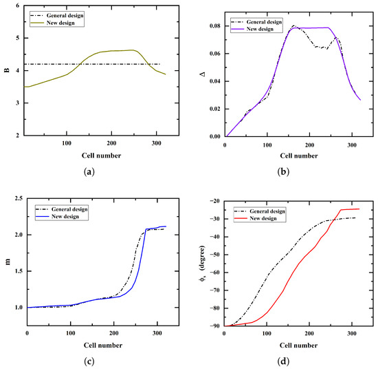
Figure 6.
Comparison of parameters between the general design and the new design along the RFQ. (a) Focusing strength factor B. (b) Defocusing factor . (c) Modulation parameter m. (d) Synchronous phase .
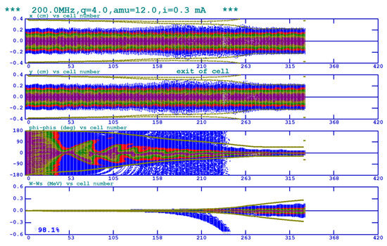
Figure 7.
New design simulation results for . Plots from top to bottom show the beam envelope evolution along the RFQ in the x and y planes, and the phase and energy spectra, respectively (color online).

Figure 8.
New design simulation results for . Plots from top to bottom show the beam envelope evolution along the RFQ in the x and y planes, and the phase and energy spectra, respectively (color online).
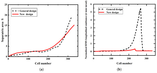
Figure 9.
Comparison results between the general design and the new design. (a) Area of the separatrix. (b) Longitudinal emittance growth (color online).
The final parameters of the RFQ are summarized in Table 2. The key parameters meet the design requirements in Section 3.1. Furthermore, compared to general design, the RFQ achieves significant improvements in transmission efficiency while maintaining high output beam quality. This advancement is primarily attributed to enhancements in the design strategy.
3.3. Multi-Particle Simulation Results
To verify the reliability of the new design strategy, additional multi-particle simulations were performed using two widely used programs, TRACEWIN [48] and TOUTATIS [49], for cross-checking. These programs provide validation of PARMTEQM simulation results by employing different field-solving methods. Unlike PARMTEQM, which models RFQ fields using a truncated cylindrical-harmonic expansion confined to a cylindrical region, TRACEWIN employs a full 3D particle-in-cell Poisson solver, while TOUTATIS solves the full Poisson equation on an adaptive multigrid mesh that precisely follows the vane geometry. By running identical RFQ geometries and beam parameters through all three codes and comparing key outputs—such as transmission efficiency and emittance—solver or algorithmic biases can be identified and mitigated, yielding more robust and reliable beam dynamics predictions. The new RFQ beam dynamics design was simulated using both programs. Each simulation employed 10,000 particles, with the RFQ input beam distributions configured as a 4D water-bag and a 3D Gaussian distribution, respectively.
The results obtained from the three multi-particle simulations are very close, as listed in Table 3 and Table 4. All deviations in transmission efficiency and emittance are small and within acceptable tolerance ranges, confirming the reliability of the proposed strategy.
Table 3.
Multi-particle simulation results using different programs ().
Table 4.
Multi-particle simulation results using different programs ().
4. Error Analysis
4.1. Input Errors Analysis
The RFQ is capable of directly receiving the input beam from the ion source and the LEBT. However, due to the instabilities of the ion source [50] and the LEBT [51,52], the practical values of the RFQ input beam may deviate from the design parameters. Thus, it is important to investigate the RFQ’s tolerance to a range of input errors. In this study, the beam emittance in the multi-ion RFQ is well controlled through optimization using the new strategy. Given this effective control, input errors have a more pronounced effect on transmission efficiency than on emittance. Therefore, the analysis primarily focuses on the impact of various input beam errors on the transmission efficiency.
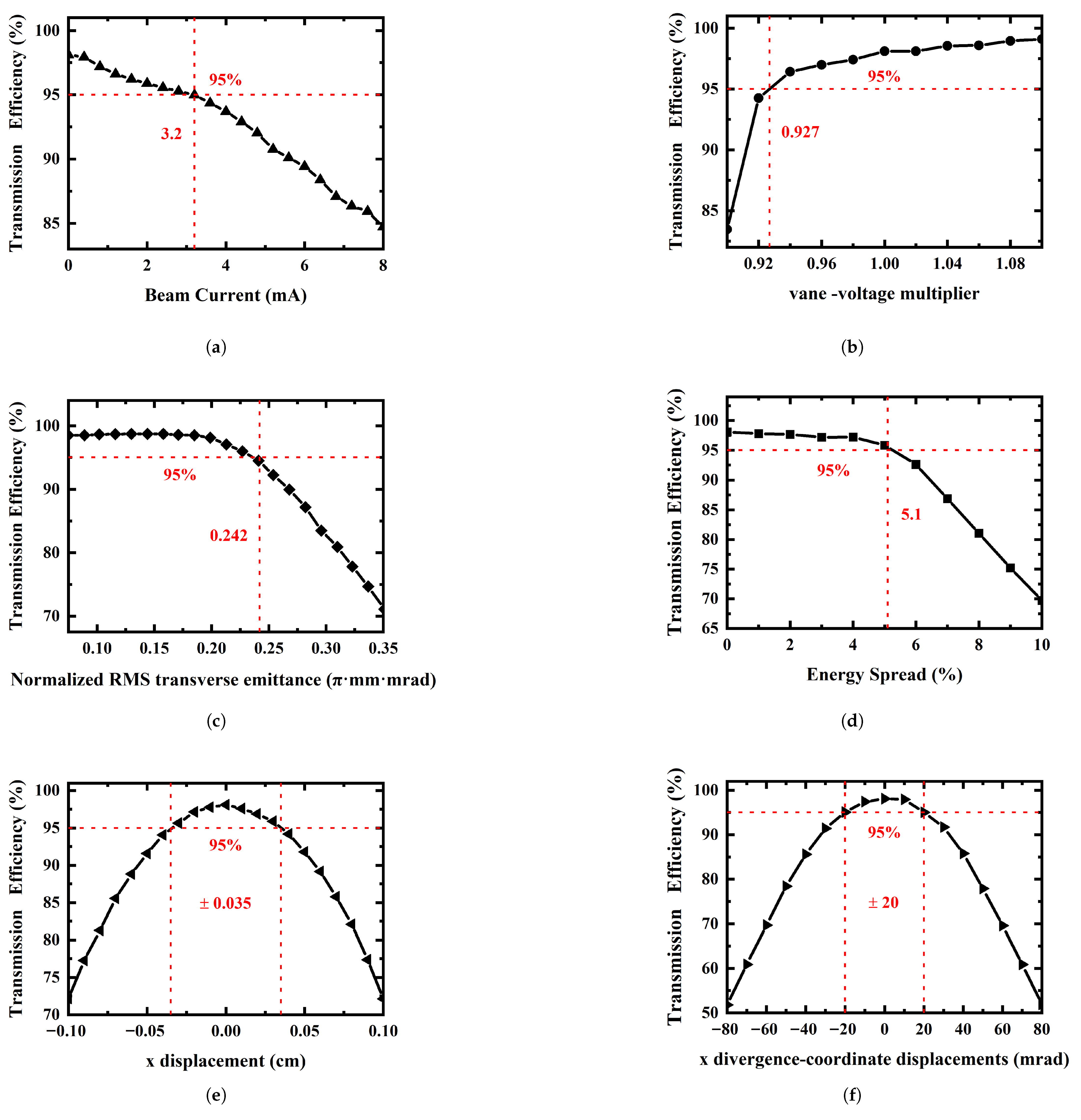
The input errors include the input beam current, vane-voltage multiplier, emittance, energy spread, spatial displacements, and divergence-coordinate displacements. The scan range of the beam parameters at the entrance of the RFQ is shown in Table 5. During the simulation, each parameter is varied individually while keeping the others constant using PARMTEQM. Figure 10 shows the transmission efficiency of the RFQ versus the input beam parameters.
Table 5.
The scan range of the beam parameters at the entrance of the RFQ.
Since the density of the ion source plasma fluctuates with changes in the source chamber temperature, voltage jitter or gas pressure, the beam current injected into the RFQ will fluctuate. As the beam current increases, space charge effects become more pronounced, leading to transverse and longitudinal phase shifts that destabilize the beam and reduce transmission efficiency [53]. For this RFQ, the required operational conditions are a beam current of 1 mA, and the transmission efficiency should be no less than 95% to ensure a safety margin of compatibility. The impact of varying input beam current on transmission efficiency is shown in Figure 10a. At 3.2 mA, the transmission efficiency remains above 95%. The analysis of space charge effects under the designed beam dynamics conditions indicates that the overall design possesses a certain level of beam current tolerance.
The vane-voltage multiplier is a scaling factor for the vane voltage [54]. As the vane voltage increases, both the longitudinal and transverse acceptances of the particles increase. Consequently, a higher inter-vane voltage leads to higher transmission efficiency. As shown in Figure 10b, when the vane-voltage multiplier exceeds 0.927 (corresponding to an inter-electrode voltage greater than 60.255 kV), a transmission efficiency of over 95% is achieved. At the design voltage of 65 kV, the transmission efficiency reaches 98.1%. However, further increasing the voltage not only requires a more powerful power source but also heightens the risk of cavity breakdown, while the improvement in transmission efficiency becomes negligible.
Figure 10c illustrates the effect of the normalized transverse emittance growth at the entrance of the RFQ. To maintain a transmission efficiency of 95%, the normalized transverse emittance should not exceed 0.242 mm·mrad. The tolerance error of the input emittance is 0.042 mm·mrad. This indicates that to improve transmission efficiency and beam quality, strict control of the emittance of the injected beam is essential.
Ideally, the RFQ accelerator can directly accept and accelerate a direct current (DC) beam with no energy spread from the ion source. However, it is limited by the stability of the ion source, the injected beam always has some energy spread. The RFQ dynamics design structure should be able to accommodate a certain level of beam energy spread. Figure 10d illustrates the variation in beam transmission efficiency with energy spread. From the figure, it can be seen that the RFQ has a good tolerance to energy spread, with transmission efficiency remaining stable above 95% for beams with an energy spread of less than 5.1%. Additionally, the degradation in beam quality due to the energy spread remains within an acceptable range.
The electromagnetic lenses in the LEBT section (including sputtering lenses and quadrupole lenses) are subject to current noise and voltage drift, which can result in spatial displacement and divergence-coordinate displacement of the beam centroid injected into the RFQ. Since the RFQ input beam is a DC beam, with symmetric error effects in the x and y directions, it is sufficient to analyze errors in one direction. As illustrated in Figure 10e,f, the beam transmission efficiency shows a wide tolerance for variations in spatial displacement and divergence-coordinate displacement. To maintain a transmission efficiency greater than 95%, the spatial displacement should be less than ±0.035 cm, and the divergence-coordinate displacement should be within ±20 mrad.
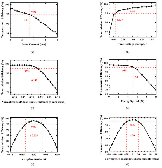
Figure 10.
Transmission efficiency of the RFQ versus input beam parameters (a) The beam current. (b) The vane voltage multiplier. (c) The input emittance. (d) The energy spread. (e) The beam spatial displacement for centroid. (f) The beam divergence-coordinate displacement for centroid.
Figure 10.
Transmission efficiency of the RFQ versus input beam parameters (a) The beam current. (b) The vane voltage multiplier. (c) The input emittance. (d) The energy spread. (e) The beam spatial displacement for centroid. (f) The beam divergence-coordinate displacement for centroid.
4.2. Mechanical Errors Analysis
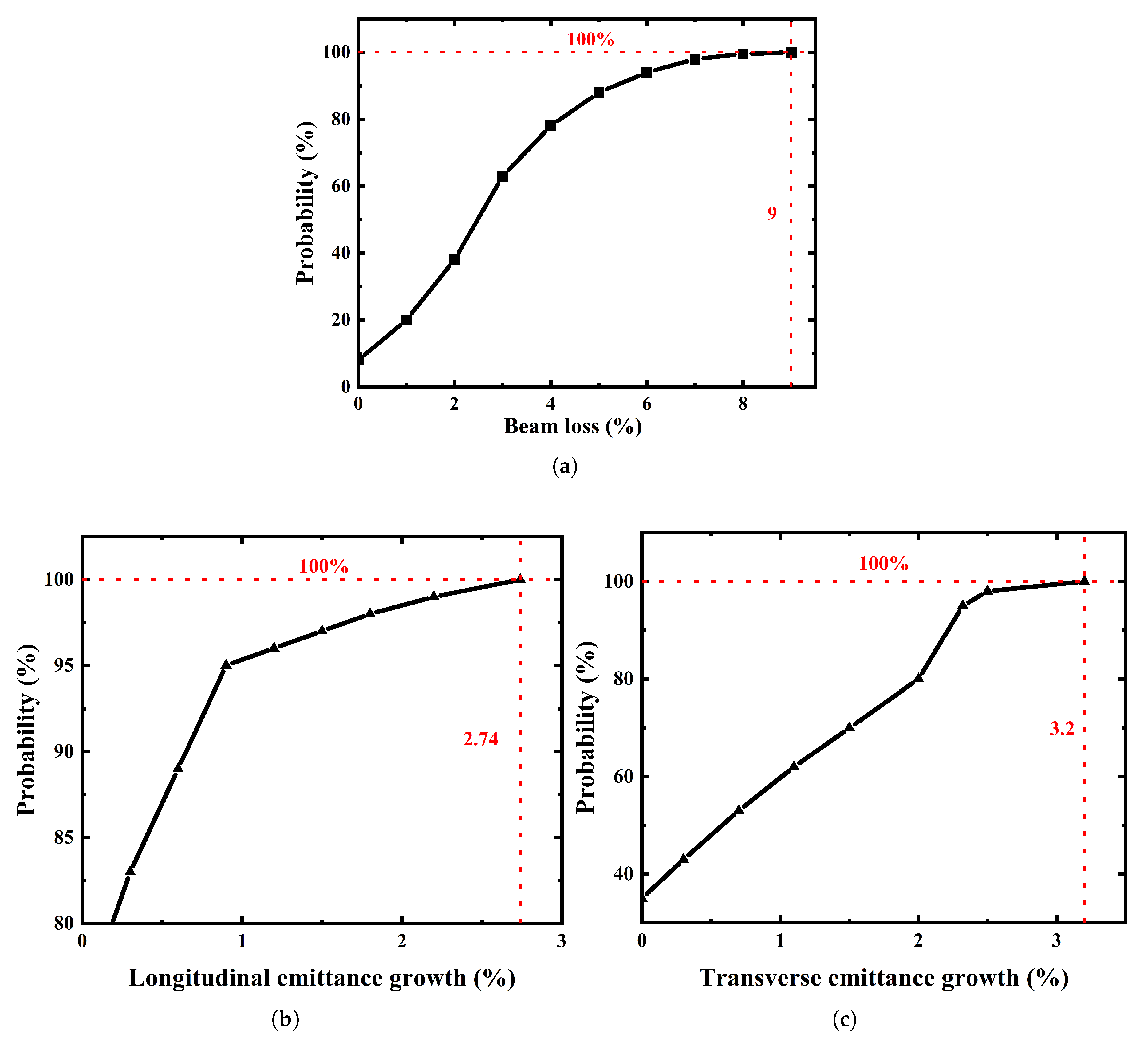
In addition to the input beam errors, there are fabrication and assembly errors that can also adversely affect the beam stable transmission and the quality of output beam. After referencing the fabrication experience of similar RFQs [18,21,31,55] and consulting with the manufacturer, the mechanical error specifications for this RFQ were determined. The mechanical error terms and their corresponding values are presented in Table 6. Mechanical error analysis is carried out using the Monte Carlo simulation method within the TRACEWIN program, which assesses the impact of errors by simulating numerous randomized cases. In each Monte Carlo trial, the values of the error items remain constant along the full length of the structure but vary randomly between different trials. After setting the error items and their corresponding ranges, TRACEWIN generates a set of random numbers uniformly distributed within the specified intervals. These values are then assigned to the RFQ electrode structure for simulation. This process is repeated 1000 times, and each simulation result is recorded and analyzed. The cumulative probability distribution graph of the results from the mechanical error analysis is shown in Figure 11.
Table 6.
The setting values of the mechanical errors.
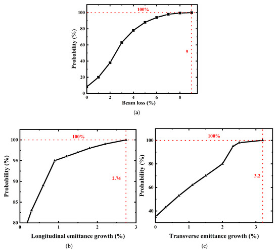
Figure 11.
Cumulative probability distribution graph of the results for the mechanical error. (a) Extra beam loss. (b) Longitudinal emittance growth. (c) Transverse emittance growth.
In Figure 11a, the maximum additional beam loss is 9% when considering mechanical errors, with a 70% probability of maintaining a transmission efficiency above 95%. In Figure 11b,c, longitudinal emittance increases by 2.74%, and the transverse emittance grows by 3.2%. The emittance growth limit for the multi-ion RFQ is set below 5%, and the extra beam loss is 10%. Both the beam loss and emittance growth meet the operational requirements. In practice, modern five-axis CNC machining routinely achieves vane-tip geometric accuracies of 20 m or better, and on-site alignment using laser trackers holds positional tolerances within 50 m over meter-scale components. Thus, the RFQ can be manufactured and assembled within the simulated error envelope with a sufficient margin, ensuring a comfortable safety factor against mechanical deviations.
5. Conclusions
This study presents the beam dynamics design and error analysis of a 200 MHz multi-ion RFQ for medical applications. A novel design strategy is proposed. By adjusting the dynamic balance between focusing and defocusing forces, the transmission efficiency at 8 mA reaches 84%, effectively enhancing the ability to suppress space charge effects. After improving the RFQ’s transverse focusing process, the input transverse emittance of 0.2 mm·mrad and the output transverse emittance of 0.1983 mm·mrad become nearly equal. After optimizing the modulation and synchronous phase, the beam is well captured, with a beam capture efficiency reaching 98.95%, and the beam quality is improved. The final simulation result achieved a transmission efficiency of over 98% for and 97% for , with a compact structure and RFQ length of 2.5 m.
Multi-particle simulations using different programs validated the reliability of the proposed design. Furthermore, comprehensive error analyses confirmed the RFQ’s sufficient tolerance to input and mechanical errors, ensuring stable operation under practical conditions. The results indicate that this multi-ion RFQ design scheme meets all the predefined requirements for medical accelerators, offering a compact and high compatibility scheme for particle therapy applications. This new proposed design strategy could benefit the next generation of RFQs for medical applications, enhances the feasibility of personalized therapy, and promotes the broader adoption of particle therapy technology in clinical practice.
Future work will be carried out in several stages. The first stage involves the RF design and multiphysics analysis of the RFQ cavity, including optimization of field flatness, as well as analyses of thermal and structural deformation. The second stage focuses on the construction and experimental validation of an RFQ prototype, encompassing mechanical alignment, low-power testing, and beam commissioning. The ultimate goal is clinical implementation.
Author Contributions
Conceptualization, X.W. and W.Z.; methodology, X.W. and W.Z.; software, X.W. and W.Z.; validation, X.W. and G.C.; formal analysis, X.W. and G.C.; investigation, X.W. and G.C.; resources, X.W. and W.Z.; data curation, X.W. and G.C.; writing—original draft preparation, X.W. and G.C.; Writing—review and editing, X.W.; funding acquisition, W.Z. All authors have read and agreed to the published version of the manuscript.
Funding
The Shanghai Advanced Research Institute, Chinese Academy of Sciences: E06G321C01.
Institutional Review Board Statement
Not applicable.
Informed Consent Statement
Not applicable.
Data Availability Statement
Data available on request due to privacy restrictions.
Acknowledgments
The author would like to thank Jameson for his useful discussions and for providing the e-book “Elements of Ion Linear Accelerators”, and Zhongshan Li and Peiyong Jiang from the Institute of Modern Physics (IMP), Lanzhou, for the code simulation.
Conflicts of Interest
The authors declare no conflicts of interest.
References
- Park, S.H.; Kang, J.O. Basics of particle therapy i: Physics. Radiat. Oncol. J. 2011, 29, 135. [Google Scholar] [CrossRef] [PubMed]
- Durante, M.; Paganetti, H. Nuclear physics in particle therapy: A review. Rep. Prog. Phys. 2016, 79, 096702. [Google Scholar] [CrossRef] [PubMed]
- Combs, S.E.; Jäkel, O.; Haberer, T.; Debus, J. Particle therapy at the heidelberg ion therapy center (hit)—Integrated research-driven university-hospital-based radiation oncology service in heidelberg, germany. Radiother. Oncol. 2010, 95, 41. [Google Scholar] [CrossRef] [PubMed]
- Noda, K.; Furukawa, T.; Fujimoto, T.; Hara, Y.; Inaniwa, T.; Iwata, Y.; Katagiri, K.; Kanematsu, N.; Mizushima, K.; Mori, S.; et al. Recent progress and future plans of heavy-ion cancer radiotherapy with himac. Nucl. Instrum. Methods Phys. Res. Sect. B Beam Interact. Mater. Atoms 2017, 406, 374. [Google Scholar] [CrossRef]
- Ohno, T.; Kanai, T.; Yamada, S.; Yusa, K.; Tashiro, M.; Shimada, H.; Torikai, K.; Yoshida, Y.; Kitada, Y.; Katoh, H.; et al. Carbon ion radiotherapy at the gunma university heavy ion medical center: New facility set-up. Cancers 2011, 3, 4046–4060. [Google Scholar] [CrossRef]
- Yang, J.; Shi, J.; Chai, W.; Xia, J.; Yuan, Y.; Li, Y. Design of a compact structure cancer therapy synchrotron. Nucl. Instrum. Methods Phys. Res. Sect. A Accel. Spectrometers Detect. Assoc. Equip. 2014, 756, 19. [Google Scholar] [CrossRef]
- Inaniwa, T.; Kanematsu, N.; Noda, K.; Kamada, T. Treatment planning of intensity modulated composite particle therapy with dose and linear energy transfer optimization. Phys. Med. Biol. 2017, 62, 5180. [Google Scholar] [CrossRef]
- Kopp, B.; Mein, S.; Dokic, I.; Harrabi, S.; Böhlen, T.T.; Haberer, T.; Debus, J.; Abdollahi, A.; Mairani, A. Development and validation of single field multi-ion particle therapy treatments. Int. J. Radiat. Oncol. Biol. Phys. 2020, 106, 194. [Google Scholar] [CrossRef]
- Ebner, D.K.; Frank, S.J.; Inaniwa, T.; Yamada, S.; Shirai, T. The emerging potential of multi-ion radiotherapy. Front. Oncol. 2021, 11, 624786. [Google Scholar] [CrossRef]
- Wangler, T.P. RF Linear Accelerators; John Wiley & Sons: Hoboken, NJ, USA, 2008. [Google Scholar]
- Ratzinger, U.; Peters, A.; Zhang, C.; Hähnel, H.; Hoeltermann, H.; Podlech, H.; Schuett, M.; Cee, R.; Altürk, S.; Haberer, T. A new rfq for the carbon therapy injector at hit heidelberg. In Proceedings of the 32nd Linear Accelerator Conference (LINAC2024), Chicago, IL, USA, 25–30 August 2024. [Google Scholar]
- Katayama, R.; Kako, E.; Yamaguchi, S.; Michizono, S.; Umemori, K.; Kondo, Y. Design study of compact medical accelerator using superconducting rf quadrupole for boron neutron capture therapy. Phys. Rev. Accel. Beams 2022, 25, 021601. [Google Scholar] [CrossRef]
- Bencini, V.; Pommerenke, H.W.; Grudiev, A.; Lombardi, A.M. 750 mhz radio frequency quadrupole with trapezoidal vanes for carbon ion therapy. Phys. Rev. Accel. Beams 2020, 23, 122003. [Google Scholar] [CrossRef]
- Budanov, Y.A.; Kalinin, V.; Frolov, B. Carbon ion injection system for a complex of radiation therapy. Phys. Part. Nucl. Lett. 2024, 21, 341. [Google Scholar] [CrossRef]
- Yap, J.; Franco, A.D.; Sheehy, S. Future developments in charged particle therapy: Improving beam delivery for efficiency and efficacy. Front. Oncol. 2021, 11, 780025. [Google Scholar] [CrossRef] [PubMed]
- Graeff, C.; Volz, L.; Durante, M. Emerging technologies for cancer therapy using accelerated particles. Prog. Part. Nucl. Phys. 2023, 131, 104046. [Google Scholar] [CrossRef]
- Kraan, A.C.; Guerra, A.D. Technological developments and future perspectives in particle therapy: A topical review. IEEE Trans. Radiat. Plasma Med. Sci. 2024, 8, 453–481. [Google Scholar] [CrossRef]
- Wang, K.-D.; Yuan, Y.-J.; Yin, X.-J.; Yang, J.-C.; Du, H.; Li, Z.-S.; Li, X.-N.; Zhao, H.; Dong, Z.-Q.; Liu, J.; et al. Fast-bunching design of compact heavy ion rfq linac. Nucl. Sci. Tech. 2018, 29, 1. [Google Scholar] [CrossRef]
- Jameson, R.A.; Yee-Rendon, B. Improved bunching and longitudinal emittance control in an rfq. J. Instrum. 2022, 17, P12011. [Google Scholar] [CrossRef]
- Vretenar, M.; Dallocchio, A.; Dimov, V.; Garlaschè, M.; Grudiev, A.; Lombardi, A.; Mathot, S.; Montesinos, E.; Timmins, M. A compact high-frequency rfq for medical applications. In Proceedings of the 27th Linear Accelerator Conference, LINAC2014, Geneva, Switzerland, 31 August–5 September 2014. [Google Scholar]
- Liu, G.; Gu, L.; Yuan, C.; Zhou, W. Beam dynamics design and error analysis of a high frequency rfq for medical application. Nucl. Instrum. Methods Phys. Res. Sect. A Accel. Spectrometers Detect. Assoc. Equip. 2024, 1069, 169930. [Google Scholar] [CrossRef]
- Mehrotra, N.; Nayak, B. Radial matching section of rfq revisited. J. Instrum. 2020, 15, T10001. [Google Scholar] [CrossRef]
- Vretenar, M.; Angoletta, M.E.; Borburgh, J.; Bottura, L.; Taylor, R.; Tranquille, G.; Benedetto, E.; Torims, T.; Paļskis, K.; Sapinski, M.; et al. Jacow: Conceptual design of a compact synchrotron-based facility for cancer therapy and biomedical research with helium and proton beams. JACoW IPAC 2023, 2023, THPM058. [Google Scholar]
- Vretenar, M.; Benedetto, E. New accelerator designs: Nimms. Health Technol. 2024, 14, 945. [Google Scholar] [CrossRef]
- Zink, K.; Baumann, K.S.; Theiss, U.; Subtil, F.; Lahrmann, S.; Eberle, F.; Adeberg, S. Organization and operation of multi particle therapy facilities: The marburg ion-beam therapy center, germany (mit). Health Technol. 2024, 14, 929. [Google Scholar] [CrossRef] [PubMed]
- Kilpatrick, W. Criterion for vacuum sparking designed to include both rf and dc. Rev. Sci. Instrum. 1957, 28, 824. [Google Scholar] [CrossRef]
- Benedetto, E.; Vretenar, M. Innovations in the next generation medical accelerators for therapy with ion beams. J. Phys. Conf. Ser. 2024, 2687, 092003. [Google Scholar] [CrossRef]
- Mairani, A.; Mein, S.; Blakely, E.; Debus, J.; Durante, M.; Ferrari, A.; Fuchs, H.; Georg, D.; Grosshans, D.R.; Guan, F.; et al. Roadmap: Helium ion therapy. Phys. Med. Biol. 2022, 67, 15TR02. [Google Scholar] [CrossRef]
- Suzuki, M.; Kase, Y.; Yamaguchi, H.; Kanai, T.; Ando, K. Relative biological effectiveness for cell-killing effect on various human cell lines irradiated with heavy-ion medical accelerator in chiba (himac) carbon-ion beams. Int. J. Radiat. Oncol. Biol. Phys. 2000, 48, 241. [Google Scholar] [CrossRef]
- Krämer, M.; Scifoni, E.; Schuy, C.; Rovituso, M.; Tinganelli, W.; Maier, A.; Kaderka, R.; Kraft-Weyrather, W.; Brons, S.; Tessonnier, T.; et al. Helium ions for radiotherapy? physical and biological verifications of a novel treatment modality. Med. Phys. 2016, 43, 1995. [Google Scholar] [CrossRef]
- Iwata, Y.; Yamada, S.; Murakami, T.; Fujimoto, T.; Fujisawa, T.; Ogawa, H.; Miyahara, N.; Yamamoto, K.; Hojo, S.; Sakamoto, Y.; et al. Performance of a compact injector for heavy-ion medical accelerators. Nucl. Instrum. Methods Phys. Res. Sect. A Accel. Spectrometers Detect. Assoc. Equip. 2007, 572, 1007. [Google Scholar] [CrossRef]
- Vormann, H.; Schlitt, B.; Clemente, G.; Kleffner, C.; Reiter, A.; Ratzinger, U. Status of the linac components for the italian hadrontherapy centre cnao. In Proceedings of the 11th European Conference, EPAC 2008, Genoa, Italy, 23–27 June 2008; p. 1833. [Google Scholar]
- Wang, K.D.; Yuan, Y.J.; Yin, X.J.; Yang, J.C.; Li, Z.S.; Du, H.; Li, X.N.; Kong, Q.Y.; Wang, K.; Dong, Z.Q.; et al. Rf design of radio-frequency quadrupole accelerator for heavy ion medical machine. Nucl. Instrum. Methods Phys. Res. Sect. A Accel. Spectrometers Detect. Assoc. Equip. 2019, 927, 375. [Google Scholar] [CrossRef]
- Kim, H.-S.; Kwon, H.-J.; Lee, S.-H.; Kim, D.-H.; Yun, S.-P.; Dang, J.-J. Development of an rfq-based compact accelerator system for ion beam applications. J. Korean Phys. Soc. 2023, 83, 140. [Google Scholar] [CrossRef]
- Crandall, K.R. RFQ Design Codes, LANL Report; Tech. Rep. LA-UR-96 (1836); Los Alamos National Laboratory: Los Alamos, NM, USA, 1836; Available online: https://scholar.google.com/scholar?hl=zh-CN&as_sdt=0%2C5&q=Crandall%2C+K.%3B+et+al.+Rfq+Design+Codes%2C+Lanl+Report%3B+Tech.+Rep.+LA-UR-96+%281836%29&btnG=#d=gs_cit&t=1748577274374&u=%2Fscholar%3Fq%3Dinfo%3A_wYCjdUns2QJ%3Ascholar.google.com%2F%26output%3Dcite%26scirp%3D0%26hl%3Dzh-CN (accessed on 25 May 2025).
- Crandall, K.; Stokes, R.; Wangler, T. Rf quadrupole beam dynamics design studies. In Proceedings of the Linear Accelerator Conference, Montauk, NY, USA, 10–14 September 1979. [Google Scholar]
- Zhang, C.; Schempp, A. Beam dynamics studies on a 200 ma proton radio frequency quadrupole accelerator. Nucl. Instrum. Methods Phys. Res. Sect. A Accel. Spectrometers Detect. Assoc. Equip. 2008, 586, 153. [Google Scholar] [CrossRef]
- Bahng, J.; Choi, B.H.; Choi, B.-H.; Kim, D.; Kim, E.-S. Development of rfq for bnct accelerator. In Proceedings of the 8th International Particle Accelerator Conference (IPAC’17), Copenhagen, Denmark, 14–19 May 2017; JACOW: Geneva, Switzerland, 2017; pp. 4260–4262. [Google Scholar]
- Kondo, Y.; Tamura, J.; Yee-Rendon, B. Reference design of the rfq for jaea ads linac. In Proceedings of the 3rd J-PARC Symposium (J-PARC2019), Tsukuba, Japan, 23–27 September 2019; p. 011015. [Google Scholar]
- Gaur, R.; Shrivastava, P. Beam dynamics and electromagnetic design studies of 3 mev rfq for sns programme. J. Electromagn. Anal. Appl. 2010, 2, 519. [Google Scholar] [CrossRef]
- Rao, S.; Singh, P. Design studies of a high-current radiofrequency quadrupole for accelerator-driven systems programme. Pramana 2010, 74, 247. [Google Scholar] [CrossRef]
- Ovsyannikov, A.D.; Ovsyannikov, D.A.; Chung, S.-L. Optimization of a radial matching section. Int. J. Mod. Phys. A 2009, 24, 952. [Google Scholar] [CrossRef]
- Zhang, C.; Schempp, A. Design of an upgradeable 45–100 ma rfq accelerator for fair. Nucl. Instrum. Methods Phys. Res. Sect. A Accel. Spectrometers Detect. Assoc. Equip. 2009, 609, 95. [Google Scholar] [CrossRef]
- Yaramyshev, S.; Barth, W.; Maier, M.; Orzhekhovskaya, A.; Schlitt, B.; Vormann, H.; Cee, R.; Peters, A. Upgrade of the hit injector linac-frontend . In Proceedings of the 11th International Conference on Heavy Ion Accelerator Technology (HIAT’09), Venice, Italy, 8–12 June 2009; pp. 6–9. [Google Scholar]
- Davidson, R.C.; Hong, Q. Physics of Intense Charged Particle Beams in High Energy Accelerators; World Scientific: Singapore, 2001. [Google Scholar]
- Reiser, M. Theory and Design of Charged Particle Beams; John Wiley & Sons: Hoboken, NJ, USA, 2008. [Google Scholar]
- Comunian, M.; Bellan, L.; Pisent, A. Comparison of longitudinal emittance of various rfqs. J. Instrum. 2024, 19, P01024. [Google Scholar] [CrossRef]
- Kumar, S.; Mandal, A. Start to end simulation of high current injector using tracewin code. In Proceedings of the 6th International Particle Accelerator Conference (IPAC2015), Richmond, VA, USA, 3–8 May 2015; MOPWA047. pp. 3–8. [Google Scholar]
- Duperrier, R. Toutatis: A radio frequency quadrupole code. Phys. Rev. Spec. Top.-Accel. Beams 2000, 3, 124201. [Google Scholar] [CrossRef]
- Gambino, N.; Adler, L.; Franco, A.D.; Ecker, F.; Farinon, F.; Guidoboni, G.; Kurfürst, C.; Myalski, S.; Penescu, L.; Pivi, M.; et al. Impact of ion source stability for a medical accelerator. J. Instrum. 2019, 14, C05017. [Google Scholar] [CrossRef]
- Sen, T.; Syphers, M. Effect of power supply ripple on emittance growth in the collider. In Proceedings of the International Conference on Particle Accelerators, Washington, DC, USA, 17–20 May 1993; pp. 146–148. [Google Scholar]
- Cao, Y.; Li, J.Q.; Sun, L.T.; Zhang, X.Z.; Feng, Y.C.; Wang, H.; Ma, B.H.; Li, X.X. An all permanent magnet electron cyclotron resonance ion source for heavy ion therapy. Rev. Sci. Instruments 2014, 85, 02A960. [Google Scholar] [CrossRef]
- Junior, P. Space-charge limits in heavy-ion rfq linacs. Part. Accel. 1983, 13, 231. [Google Scholar]
- Crandall, K.R.; Wangler, T.P.; Young, L.M.; Billen, J.H.; Neuschaefer, G.H.; Schrage, D.L. RFQ Design Codes; LA-UR-96-1836; Los Alamos National Laboratory: Los Alamos, NM, USA, 2005. [Google Scholar]
- Eshraqi, M.; Prisco, R.D.; Miyamoto, R.; Edgar, S.; Dølrath, T.H. Statistical error studies in the ess linac. In Proceedings of the 5th International Particle Accelerator Conference, IPAC 2014, Dresden, Germany, 15–20 June 2014; pp. 3323–3325. [Google Scholar]


Disclaimer/Publisher’s Note: The statements, opinions and data contained in all publications are solely those of the individual author(s) and contributor(s) and not of MDPI and/or the editor(s). MDPI and/or the editor(s) disclaim responsibility for any injury to people or property resulting from any ideas, methods, instructions or products referred to in the content. |
© 2025 by the authors. Licensee MDPI, Basel, Switzerland. This article is an open access article distributed under the terms and conditions of the Creative Commons Attribution (CC BY) license (https://creativecommons.org/licenses/by/4.0/).