1. Introduction
Metasurfaces, as two-dimensional metamaterials, have been extensively studied since they were first proposed in 2011 [
1]. Metasurfaces are typically composed of subwavelength scattering elements made of metals or dielectrics with specific shapes and arrangements, which offer the advantages of thin thickness, easy fabrication, and low production cost [
2,
3]. By locally adjusting the responses of each meta-atom, metasurfaces have the remarkable abilities to control the electromagnetic amplitude, phase, and polarization, which have been applied in widespread fields such as optics, communications, and sensing [
4,
5,
6,
7,
8,
9,
10,
11,
12].
The Huygens’ metasurface is an artificial electromagnetic surface designed based on the Huygens’ principle [
13], exhibiting the powerful ability to control incident waves accurately. The meta-atom of a Huygens’ metasurface consists of electric and magnetic resonators, which can simultaneously provide electric and magnetic current responses to full control of the electromagnetic fields. When the induced magnetic current and intrinsic electric current are balanced, the Huygens’ resonance is excited. Utilizing this effect, nearly unity transmission amplitude and full
phase coverage can be achieved. Therefore, Huygens’ metasurfaces exhibit great application value and broad prospects in fields such as microwave communication, wireless power transfer, radar systems, and antenna design [
14,
15,
16,
17,
18,
19,
20].
Huygens’ metasurfaces also play a crucial role in metalens antennas. Traditional transmitarray (TA) employing multilayer frequency-selective surface (FSS) enables full phase control, breaking the constraints of conventional optics laws [
21,
22]. However, such a TA generally requires a multilayer structure to achieve phase control, resulting in incompact structure and difficult fabrication. Double-layer Huygens’ metasurfaces offer a compact and cost-effective alternative. Various Huygens’ metasurfaces with double-layer structure have been developed for metallic lens antennas and anomalous refraction applications, including anti-symmetric metallic elements [
23], symmetric dual-polarized metallic elements [
24,
25], and electric dipole pairs [
26]. Several double-layer Huygens’ metalens antennas with distinct characteristics have been reported in recent years. For instance, a dual-polarized Huygens’ metasurface has been proposed to achieve high-gain transmission [
23,
27,
28], and Wu et al. reported a highly transmissive Huygens’ metasurface with a thickness of only 0.033 times of wavelength [
29]. Moreover, a two-functional metasurface has been demonstrated to independently manipulate differently polarized beams [
30,
31]. These designs provide advantages in terms of phase control, operational bandwidth, and functional integration, offering improved solutions for applications such as waveform shaping, focusing, and asymmetric reflection [
32,
33,
34].
In this work, we propose a new ultrathin double-layer anisotropic meta-atom based on the principle of Huygens’ resonance. The meta-atom features an ultrathin thickness while maintaining high transmission. Two types of metalens based on the dual-polarization and two-channel characteristics of the meta-atom are designed. Our work provides a more flexible solution for the design of transmissive devices, allowing different types of metasurfaces to be realized using the same meta-atom. Moreover, the proposed Huygens’ metasurface features a double-layer, ultrathin structure that not only significantly reduces fabrication complexity and cost but also enhances integration potential, thereby facilitating device miniaturization and lightweight development. Simulating results demonstrate that this meta-atom holds strong potential and feasibility for the design of various electromagnetic devices.
This work is organized as follows:
Section 2 introduces the design principles and structure of the meta-atom, and demonstrates the Huygens’ resonance phenomenon. In
Section 3, a dual-polarized directional radiation metalens antenna is designed and discussed. In
Section 4, we design a two-channel focusing metalens utilizing the capability to control polarization independently of the meta-atom. Finally,
Section 5 concludes this work.
2. Theoretical Analysis and Design of Huygens’ Meta-Atoms
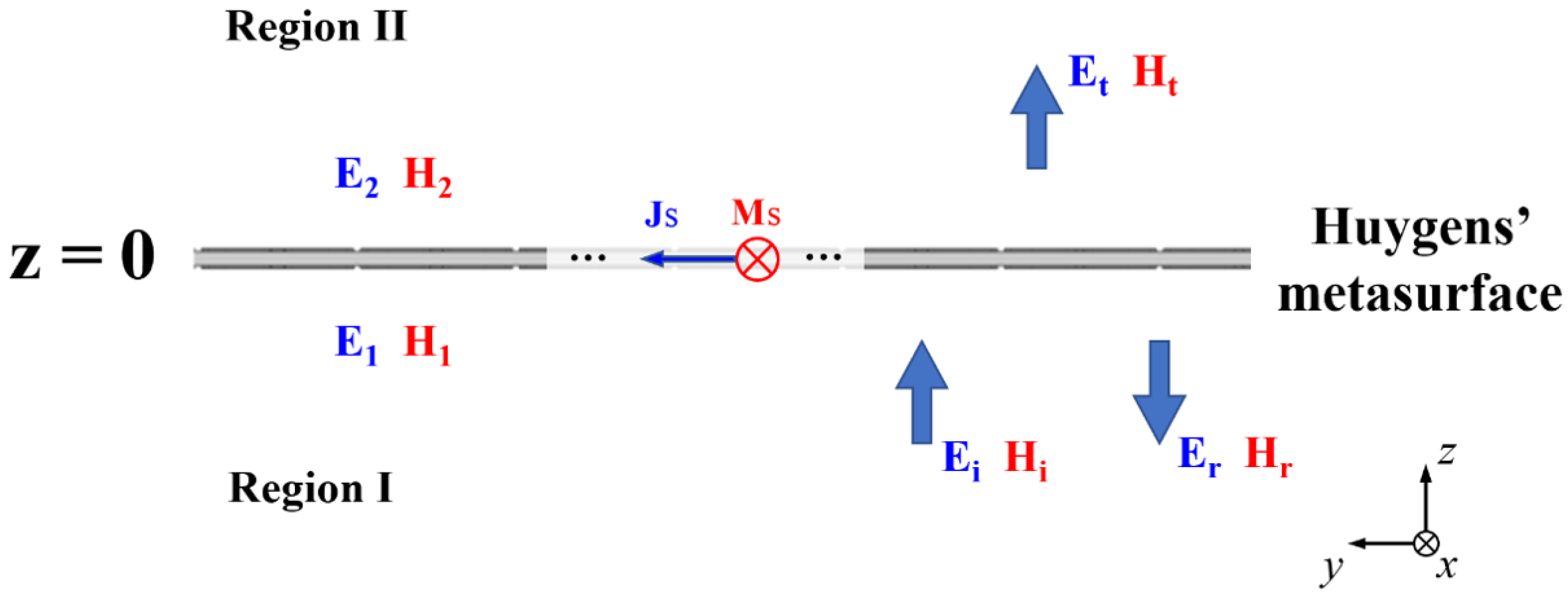
The design of Huygens’ metasurface is essentially an application of the Huygens’ principle. Each meta-atom on the metasurface acts like a secondary wave source in Huygens’ principle, alters the local wavefront, and thereby achieves precise control over the overall wavefront of the propagation waves. The schematic diagram of the Huygens’ metasurface is illustrated in
Figure 1. The domain is divided into two regions by the metasurface. The fields in region 1 are the incident waves
,
and the reflected waves
, and the fields in region 2 are the transmission waves
. The fields in both regions induce the electric surface current densities
and the magnetic surface current densities
on the metasurface, which should satisfy the following expressions:
where the subscripts 1 and 2 denote the field on the metasurface in region 1 and region 2, respectively. Here,
and
,
represents
or
.
and
are the surface average tangential electric and magnetic fields. The electric surface admittance tensor
and the magnetic surface impedance tensor
can fully characterize the material properties of the metasurface. Depending on the given incident polarization, the tensors
and
are simplified to scalar quantities. Accordingly, they can be extracted from the transmission
and reflection
coefficients [
13]:
where
and
are the normalized admittance and impedance, respectively. The superscript
i represents the polarization direction of the incident wave, which is denoted as
x or
y.
represents the free-space impedance. When designing a transmissive metasurface, it is generally desirable to achieve zero reflection
and near-unity transmission
. Research demonstrates that when the real parts of
and
are zero and their imaginary parts are equal, the Huygens’ resonance is excited, which will achieve the near-unity [
13].
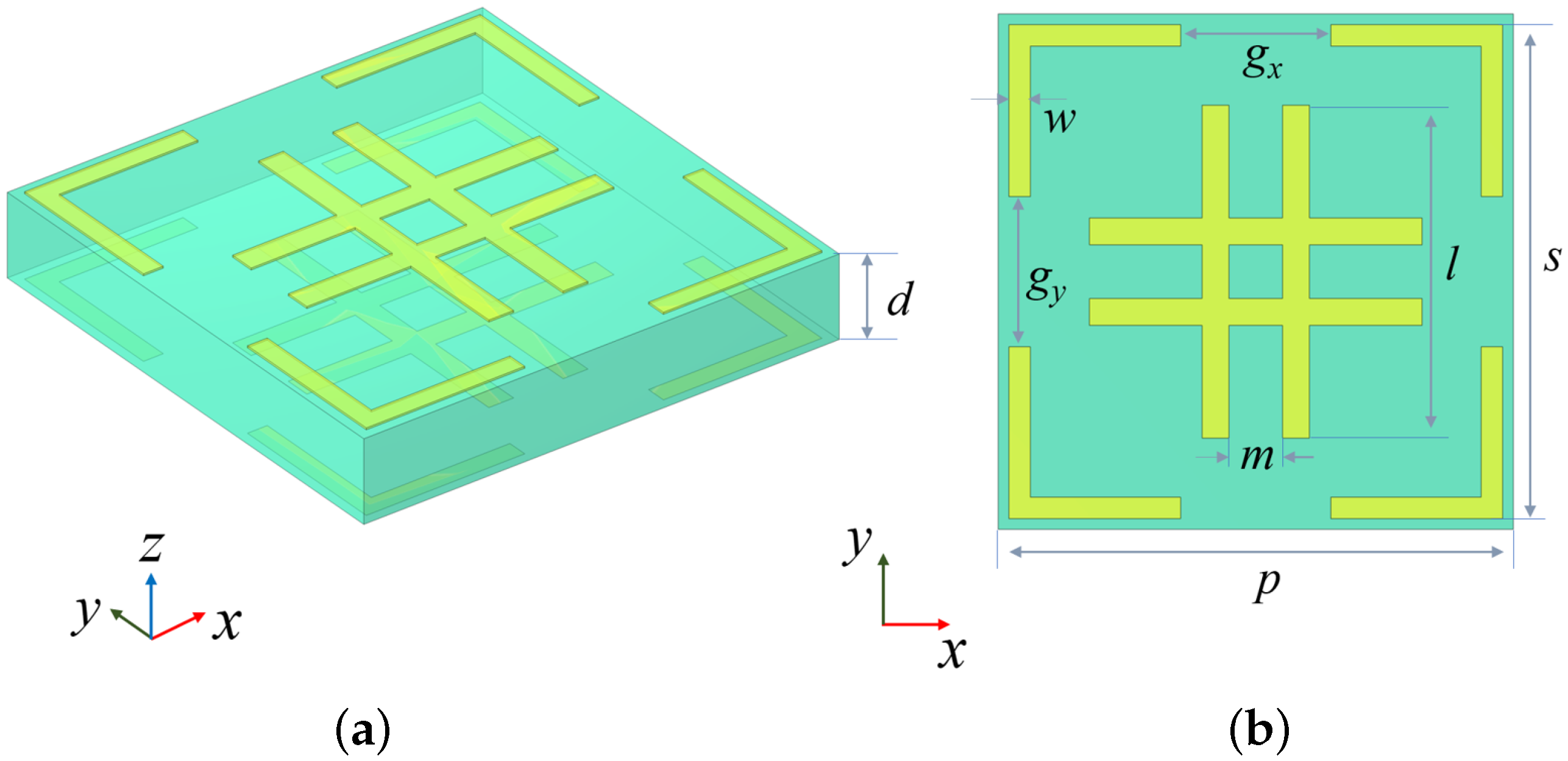
Figure 2 shows the structure configuration of the designed Huygens’ meta-atom. The meta-atom consists of double-layer metallic patches on each side of a dielectric substrate. The top and the bottom metallic patches have identical geometric structures, comprising a double-cross shape and a corner-ring shape. The double-cross shape consists of two parallel horizontal rectangles intersecting with two parallel vertical rectangles. The parallel rectangles have a length of
mm, with the spacing of
mm. On the other hand, the size of the corner-ring-shaped patches is
mm, with gaps between adjacent corner-ring patches. The gaps along different directions are denoted as
and
, respectively. Both the double-cross-shaped patches and the corner-ring-shaped patches use the same width of
mm and thickness of 0.018 mm. The metallic patches are fabricated using copper (electrical conductivity
S/m) with a thickness of
mm. The dielectric substrate has a thickness of
mm and is made of Rogers RT5880 material with a relative permittivity of 2.2 and a loss tangent of 0.0009. The side length of the proposed Huygens’ meta-atom is
mm.
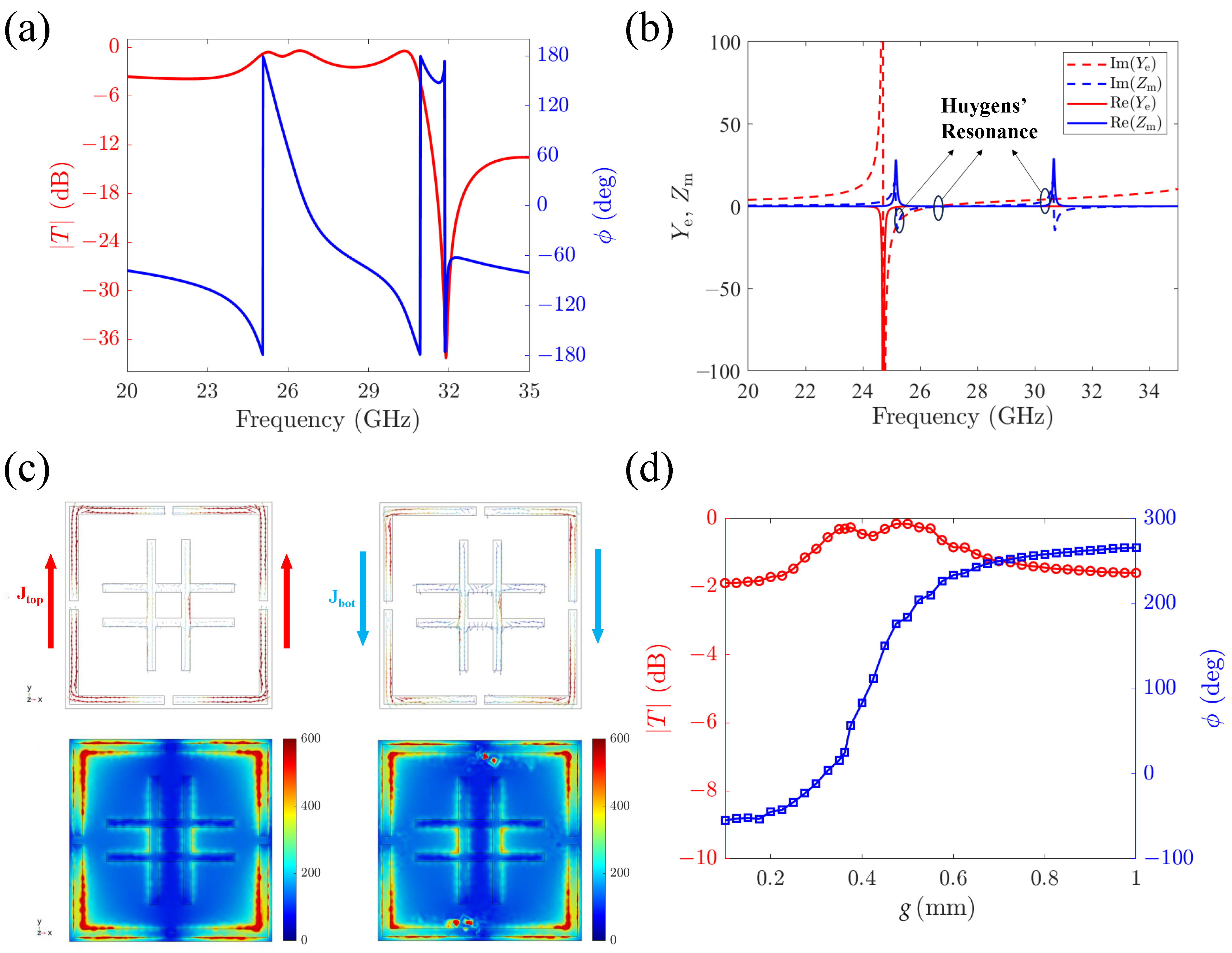
In order to investigate the resonance modes and physics mechanisms of the proposed meta-atom, full-wave simulations were performed in commercial software CST Microwave Studio 2020, considering the dual-polarized scenario, i.e.,
mm. Because of the symmetrical structure in this situation, the meta-atom exhibits identical responses to both
x- and
y-polarized incident waves. The following analysis is performed based on the
y-polarized normal incident wave.
Figure 3a illustrates the transmission amplitude and phase of the proposed meta-atom on the frequency range from 20 GHz to 35 GHz. A transmission peak is observed with an amplitude of
dB, indicating the near-unity transmission amplitudes at frequency
GHz. More importantly, the proposed meta-atom maintains high transmission
and full-phase coverage over a broad frequency range from 24 GHz to 31 GHz, which facilitates the subsequent meta-lens antenna design and the high-gain requirement.
Furthermore, the Huygens’ resonance is explained by analyzing the frequency response of the normalized electric surface admittance
and magnetic surface impedance
. As shown in
Figure 3b, three Huygens’ resonance points are identified, which are characterized by the phenomena that the imaginary parts of
and
are equal, while the real parts are nearly zero. According to Equation (
2), the electric and magnetic resonances are balanced at these frequencies, generating nearly full transmission over a broad frequency band.
Figure 3c demonstrates the electric current distribution and the magnetic field distribution on the top and bottom surfaces of the meta-atom at 25.2 GHz, in which the transmission amplitude has a peak value. It can be seen that when the meta-atom is excited by the
y-polarized wave, the surface currents are induced in the corner-ring-shaped patches of the top and bottom layers, which are denoted as
and
. The
flows along the +
y direction while the
flows along the -
y direction. Such oppositely directed currents form a closed current loop, generating an orthogonal magnetic field. In contrast, the double-cross-shaped patches support relatively weak surface currents, which only contribute to providing electric resonance. Therefore, the Huygens’ metasurface simultaneously controls both electric and magnetic resonances, and a balance of these is achieved at 25.2 GHz, which results in Huygens’ resonance.
In order to ensure that the desired high transmission and wide phase coverage can be achieved by varying the structural parameter at the Huygens’ resonance point, the relationship between the transmission coefficient and the gap widths of the corner-ring-shaped patches
g at 25 GHz is plotted, as shown in
Figure 3d. As
g varies from 0.1 mm to 1 mm, the transmission amplitude of the meta-atom remains above –1.9 dB, with a maximum transmission amplitude of –0.3 dB. Meanwhile, the transmission phase covers a range of
, which is nearly full phase coverage and sufficient for the design of the metalens. Thus, both the amplitude and phase coverage meet the design requirements for the metalens.
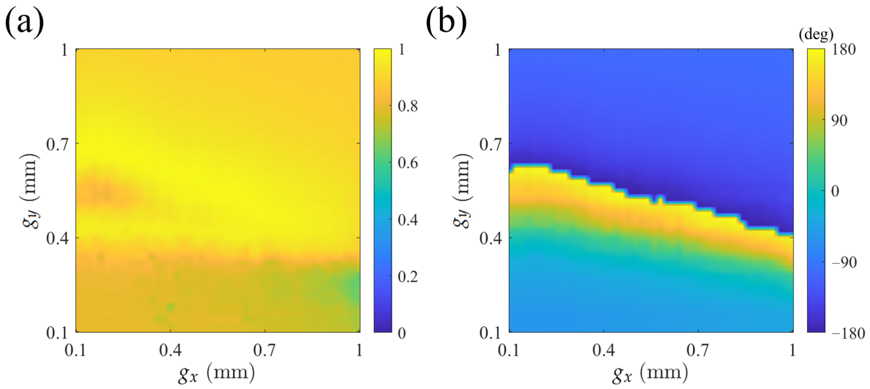
Moreover, the dependence of the polarization excitation is investigated by controlling
and
separately.
Figure 4 shows the transmission coefficients under
y-polarized excitation at 25 GHz. It can be seen that the meta-atom maintains high transmission in most situations as
and
vary. Due to
controlling the response to
y-polarized waves, the phase distribution exhibits significant variation along the
y-axis, while remaining slightly varying along the
x-axis. A similar phenomenon can also be observed under
x-polarized excitation, which is not shown for simplicity. Within acceptable errors, it can be concluded that the
and
can independently control the responses to the corresponding polarization, indicating the polarization excitation independence of the meta-atom. The investigation demonstrates that the devices implemented based on the proposed Huygens’ metasurface have the potential for two-channel or multi-channel operation.
3. Design and Discussion of a Dual-Polarized Metalens Antenna
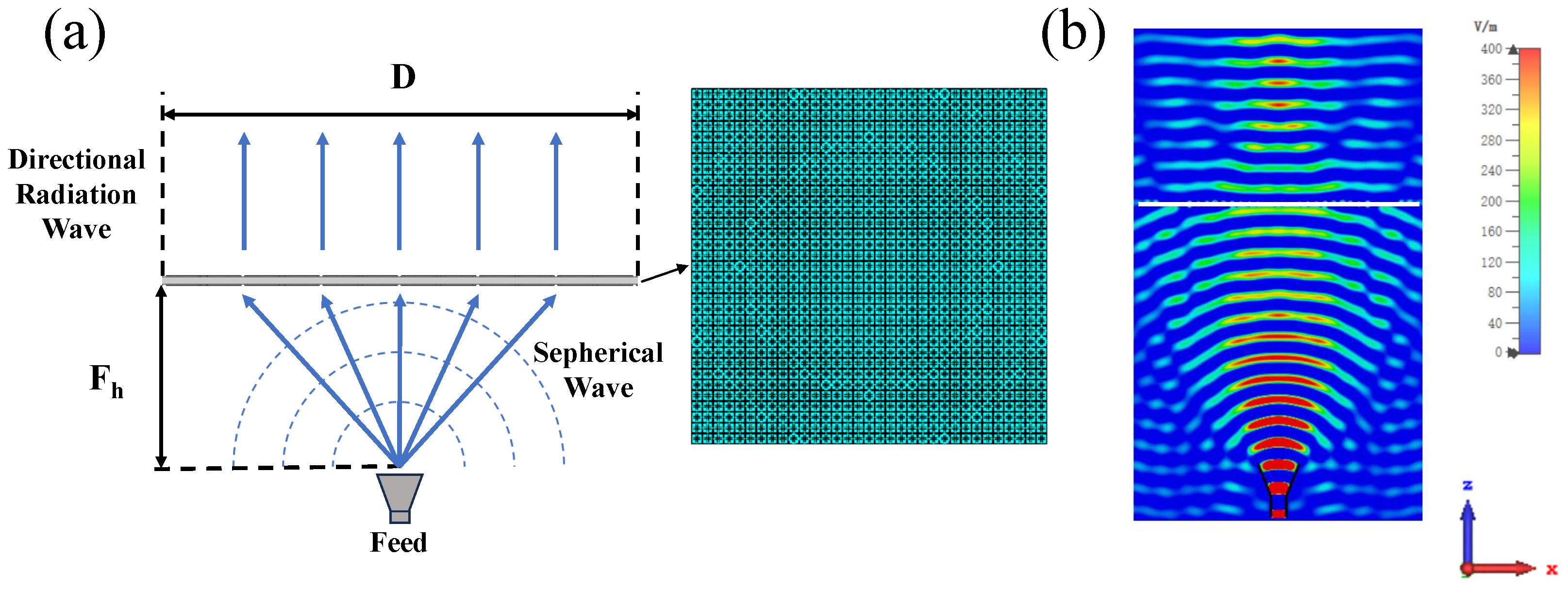
To validate the applicability and practical performance of the proposed meta-atoms, a dual-polarized metalens antenna was designed. As analyzed in
Section 2, when
, the meta-atom can produce identical responses to incident waves with different polarization directions, realizing the dual-polarized function. The dual-polarized metalens is designed to transform the spherical wavefront generated by a feed source into a planar wavefront, thereby achieving high-gain and highly directional radiation beams. The directional radiation metalens can be regarded as the inverse of the focusing metalens. By placing the feed antenna at the focal point, the emitted spherical wave is transformed into a highly directional plane wave by the metalens. A 25 GHz horn antenna with
dBi gain is vertically placed at the focal point of the metalens with a distance of
. Then, the discretized phase distribution for the metalens can be calculated as follows:
where
p is the period of the meta-atoms,
represents the position of the unit cell on the metalens. The center coordinates of the unit cell can be expressed as
, with the corresponding phase
.
is the operating frequency and
c is light speed in vacuum.
is the focus length. The metalens antenna contains
meta-atoms with an aperture size of
. The parameters chosen in this work are: operating frequency
GHz, focus length
mm, focal-diameter ratio
.
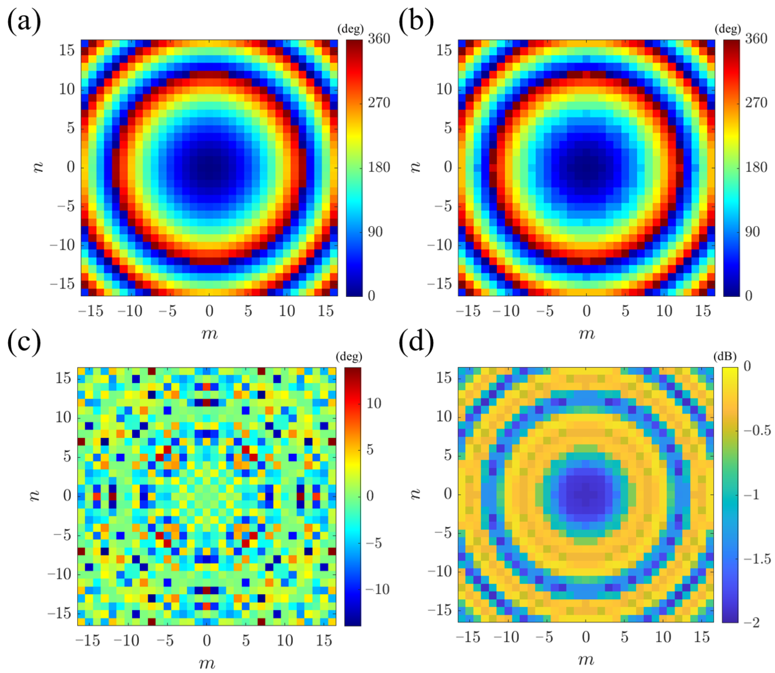
Figure 5a shows the theoretically calculated transmission phase distribution of the metalens, obtained through Equation (
3). The proposed meta-atoms are mapped onto the theoretical phase, with the actual phase shown in
Figure 5b. Due to the discrete phase approximation of meta-atoms, phase errors arise between the implemented and theoretical designs, as plotted in
Figure 5c. Notably, the phase errors are very small, with the majority of them approaching zero, and the maximum deviation being lower than
. Meanwhile, the gain is determined by the transmission amplitude. As seen in
Figure 5d, the amplitude distribution across the entire metalens aperture remains above
dB, demonstrating high transmittance. Thus, the amplitude and phase of the implemented meta-atoms mapping satisfy the theoretical requirements.
In order to validate the electromagnetic properties of the designed metalens, simulations are performed in CST Microwave Studio. The simulation domain was set to
. The open boundary conditions were applied in all boundaries, and the phase center of the horn antenna feed source was positioned at
. The configuration of the designed metalens antenna is illustrated in
Figure 6a, and the results of
are shown in
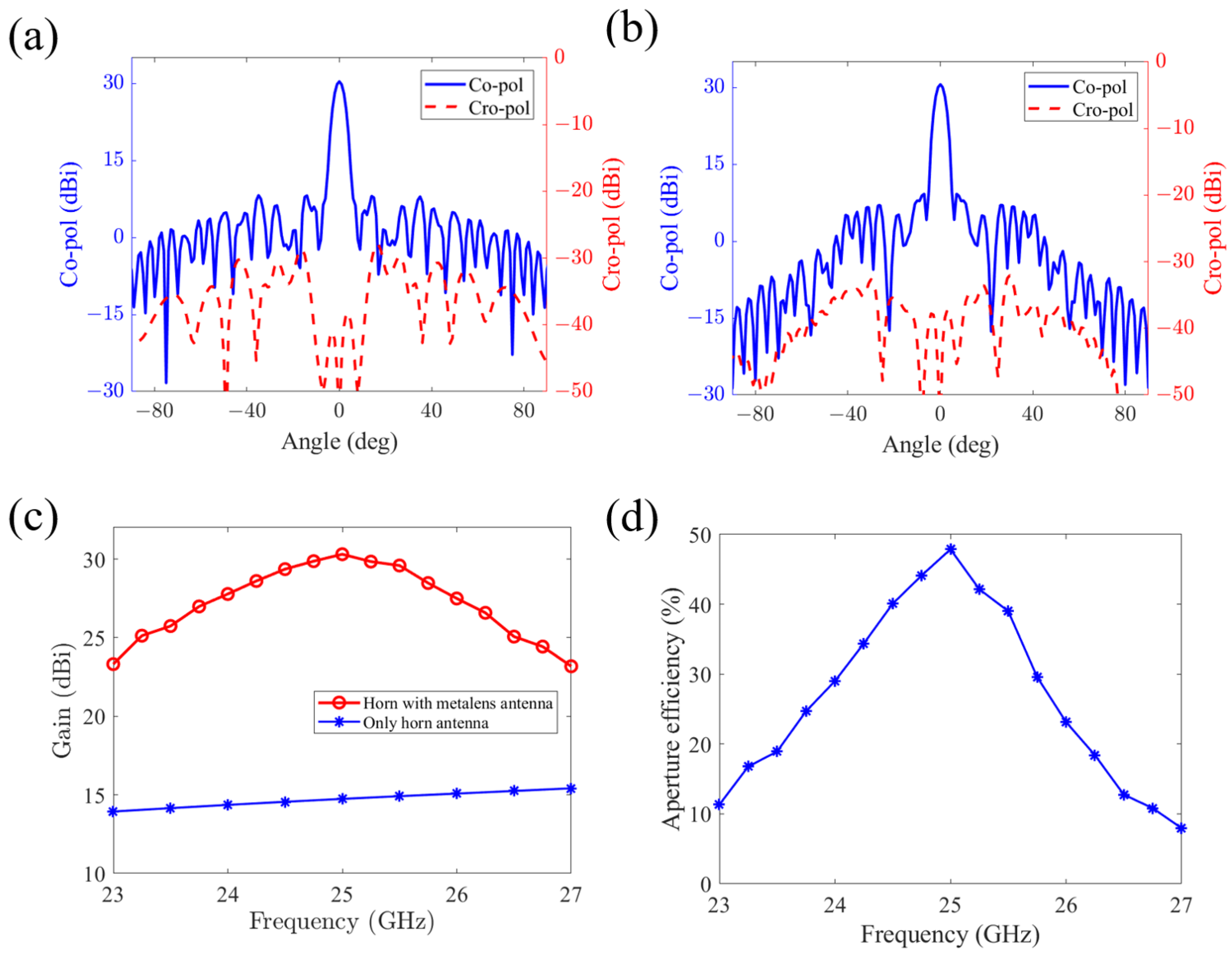
Figure 6b. It can be seen that the spherical wave generated by the feed source is converted into a directional radiation plane wave after propagating through the metalens. To further demonstrate the directional radiation capability of the metalens, the far-field radiation patterns of
E-plane and
H-plane are plotted in
Figure 7a,b. The simulation results show that a highly directional beam is generated by the designed metalens with a maximum gain of 30.4 dBi. The 3 dB gain bandwidth in the
E- and
H-plane are
and
, respectively, and the sidelobe levels are 8.16 dBi and 9.23 dBi. In addition, the cross-polarization level is below −28.3 dBi and −30.8 dBi for the
E- and
H-plane, respectively, which is significantly lower than the co-polarization levels. These results demonstrate that the designed metalens antenna exhibits outstanding far-field radiation directivity and low cross-polarization levels.
Figure 7c illustrates the radiation gain of the metalens antenna under
y-polarized spherical wave excitation, as well as the gain of the feed source. It can be obviously seen that the metalens antenna significantly enhances the radiation gain of the horn antenna, achieving a maximum gain of 30.4 dBi at 25 GHz and a half-power bandwidth ranging from 23.9 GHz to 26 GHz, which corresponds to a relative bandwidth of approximately 8.4%.
Figure 7d presents the aperture efficiency, which shows that the maximum aperture efficiency of 47.8% is achieved at 25 GHz.
Furthermore, compared with conventional metasurfaces or Huygens’ metasurfaces, whose thickness typically exceeds one-tenth of the wavelength, the proposed metalens antenna features a dielectric substrate with a thickness of only one-fifteenth of the wavelength at the design frequency of 25 GHz. More comparisons with the performance of previously published metalens antennas are presented in
Table 1. It can be seen that the proposed metalens achieves outstanding performance while maintaining a thin thickness, which is favorable for device integration and miniaturization. This makes it highly valuable and promising for applications in the K-band.
4. Design and Discussion of a Two-Channel Focusing Metalens
Dual- or multi-channel devices based on different polarization excitations have been widely applied, facilitating the realization of polarization multiplexing and multifunctional integration [
35]. We applied the proposed Huygens’ meta-atom on the two-channel focusing metalens, which generates different focal points for different polarizations. According to the meta-atom analyzed in
Section 2, tuning
and
allows independent control of the phase responses by the corresponding polarizations. Thus, utilizing this characteristic, the phase distributions for the
x-polarized and
y-polarized incident waves are independently designed to achieve two-channel focusing.
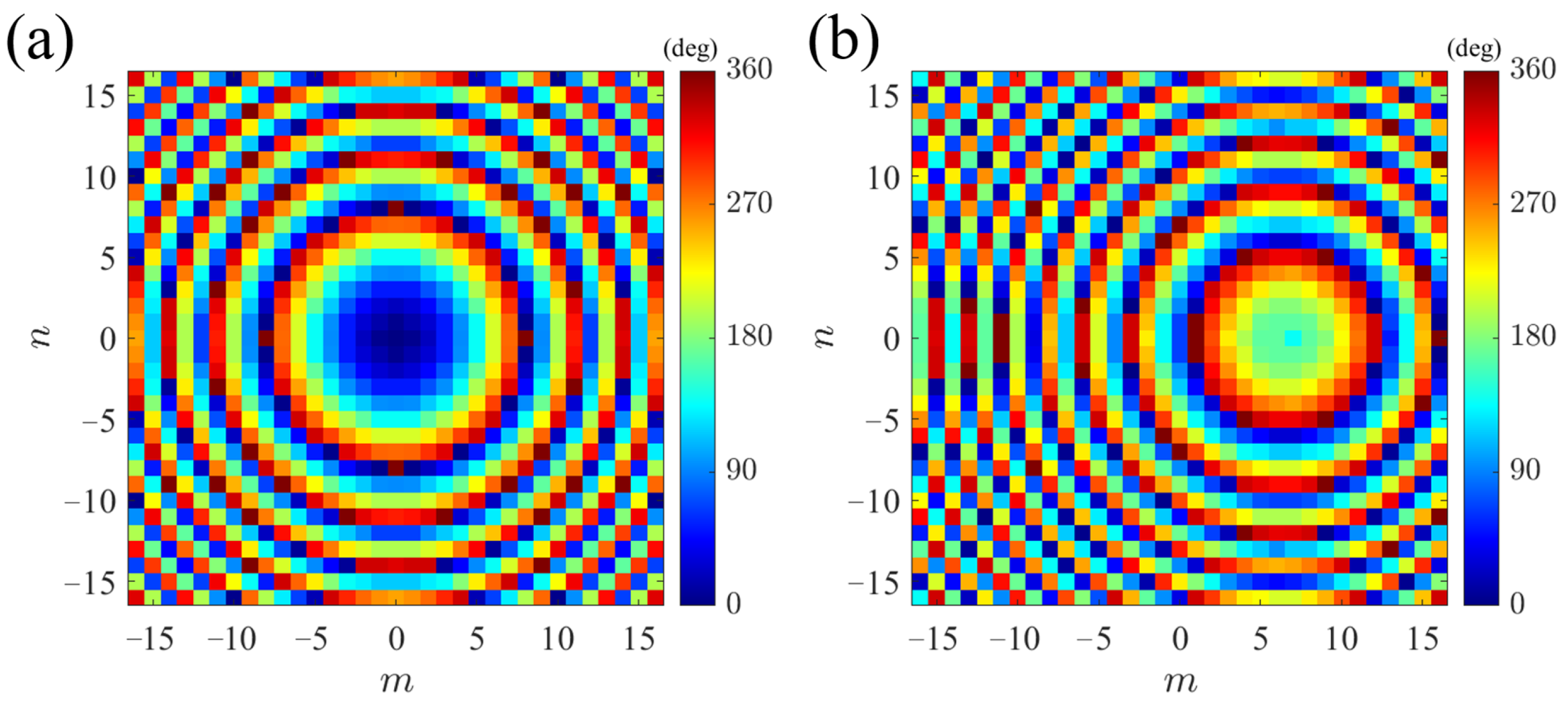
To realize the designed function, the spherical wave excitation is converted into a plane wave by introducing the phase compensation
as Equation (
3), and then the resulting plane wave is focused using a focus phase
. Assuming the focal point is located at
,
is given by:
The total phase
of the metalens in this Section is the sum of Equation (
3) and (
4), which is expressed as:
The designed metalens shares the same dimensions and operating frequency as those in
Section 3. With
mm, the horn antenna feed source is located at
mm, whose azimuth angle is set to
to simultaneously excite both
x- and
y-polarized spherical waves. The different channels of waves are focused at
mm and
mm. Based on Equation (
5), the calculated phase compensation distributions for the
x- and
y-polarized channels are shown in
Figure 8.
According to the discrete phase distributions, the designed meta-atoms are mapped and assembled into the metalens. The two-channel functionality of the implemented metalens is then verified using CST.
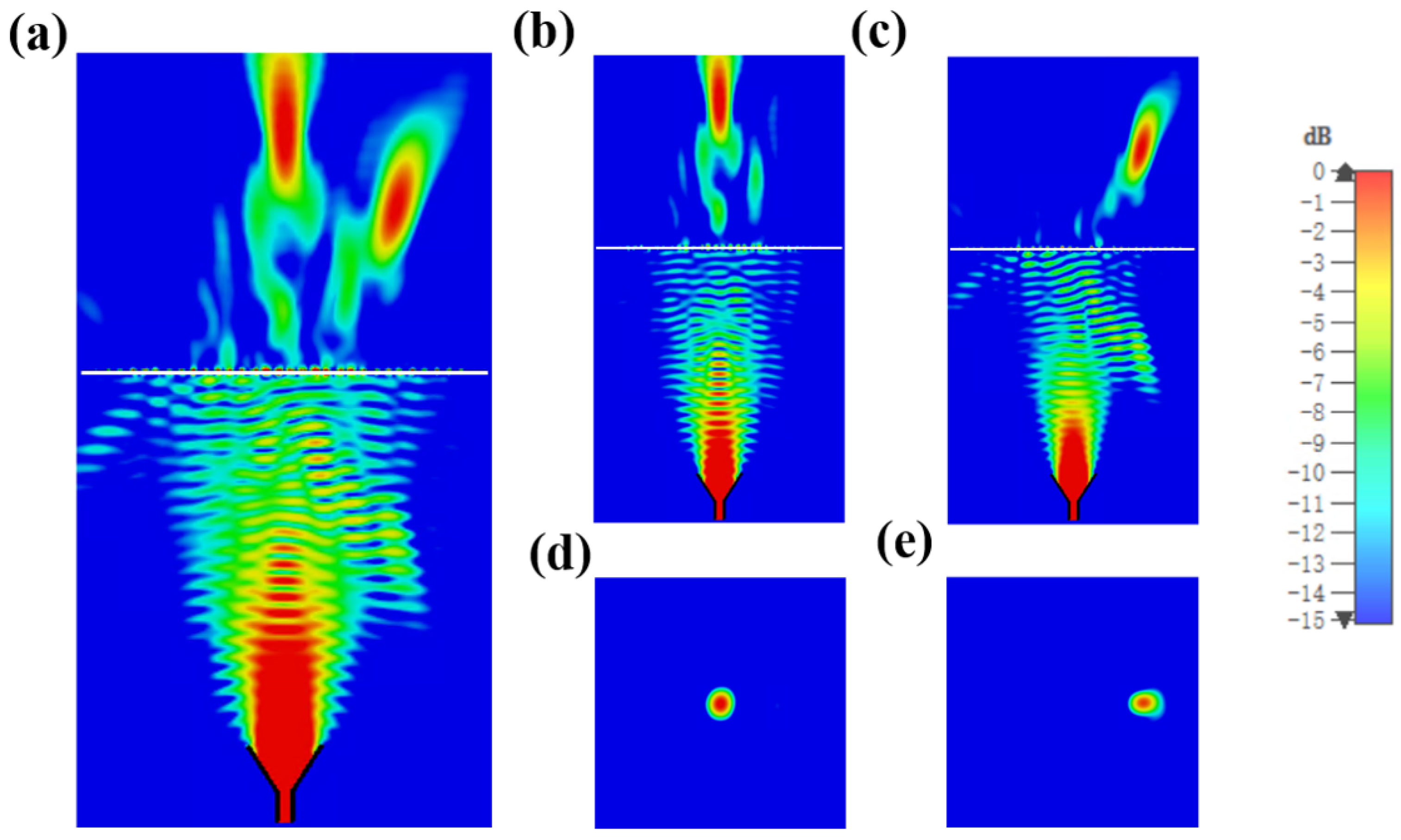
Figure 9a shows the normalized electric field distribution of
. It can be seen that the spherical incident waves, including both
x- and
y-polarized components, generate two different focus points after propagating through the metalens.
Figure 9b,c show the normalized electric field distributions of
and
to describe the response of the metalens to specific field components, which illustrate that each of the focal points originates from the incident fields of the corresponding polarized wave. The two focal points are relatively independent, demonstrating the successful realization of the designed two-channel functionality. Then, the field distributions on the focal plane under
x- and
y-polarized incidences are plotted separately in
Figure 9d,e, which confirm that the positions of the focal points are consistent with the preset design. Furthermore, we define the focusing efficiency as the ratio of the energy of the central spot region (within a width of three times the full width at half maxima) to the total energy on the incident side. The operational bandwidth ranges from 24 GHz to 27.8 GHz. Thus, the focusing efficiencies of the designed two-channel focusing metalens are calculated to be 52.4% for
x-polarization and 48.6% for
y-polarization, respectively, achieving an excellent focusing effect in each channel.
After completing numerical simulation verification, the designed metasurface can be fabricated and experimentally tested. The fabrication process is as follows: Firstly, preparation of a Rogers RT5880 substrate with a thickness of 0.8 mm as the substrate material. Secondly, using PCB fabrication techniques, including masking and photolithography, copper patches with a thickness of 0.018 mm are deposited on both sides of the substrate according to the designed metasurface patterns. Finally, clean the fabricated sample and apply anti-oxidation treatment to ensure the performance of the metasurface and prevent phase errors caused by copper oxidation. After that, the electromagnetic properties of the fabricated metasurface can be tested and verified under experimental conditions [
36,
37]. It is worth noting that the Huygens’ metalens operates based on electromagnetic resonances between both sides of metasurface, precise alignment of the patterned copper layers during the photomask process is critical. The fabrication process of the designed metalens in this work is relatively simple, based on mature techniques, and cost-effective.


