Abstract
The high water head of some pumped storage power stations will induce the cracking of the concrete lining of their diversion tunnel and the leakage of high-pressure water, which will affect the safety of the tunnel and the surrounding rock. At present, there is no solution to the problem of impermeability of concrete materials after cracking. This paper proposes a composite lining to solve this problem. The composite lining with modified polydimethylsiloxane coating can effectively prevent high-pressure water, but its crack resistance needs to be further studied. Therefore, the tensile mechanical properties, constitutive relationship of modified polydimethylsiloxane impermeable coating, and the crack resistance mechanical properties of modified polydimethylsiloxane impermeable composite lining were studied by laboratory tests and numerical simulations. The results show that the true fracture elongation of the modified polydimethylsiloxane impermeable coating is as high as 118.98%, and its mechanical behavior can be described by a simplified polynomial hyperelastic constitutive model. The in situ stress will affect the crack width of the concrete lining. When the lateral pressure coefficient is less than 1, the crack width decreases with the increase in the lateral pressure coefficient. When the lateral pressure coefficient is greater than 1, the crack width increases with the increase in the lateral pressure coefficient. To prevent the cracking of modified polydimethylsiloxane coating, its spraying thickness needs to increase with the increase in crack width. The ratio of the coating’s thickness to crack width is recommended from 0.162 to 1.930 for internal water pressure from 1 MPa to 10 MPa, respectively. The suggestion provides a reference for designing the impermeable composite lining structure subjected to high internal water pressure.
1. Introduction
Compared with traditional reservoir, a pumped storage power station has more obvious advantages in flood control and economy, which is a major focus of future development [1,2]. A diversion tunnel is an important part of a pumped storage power station, which has the function of water conveyance and drainage. Due to the large number of construction of pumped storage power stations, there are many high-pressure tunnels with internal water head of more than 100 m in China [3], and the highest hydrostatic head can reach 800 m [4]. Under the condition of high water head, the cracking of reinforced concrete lining of the tunnel is inevitable. The problem of internal water leakage of concrete lining often occurs in the middle and lower sections of the diversion tunnel. For example, in 2005, the JPower power station experienced a transformer short-circuit fault due to water inflow from the diversion tunnel [5]. Therefore, the innovative design of the lining structure and the simulation analysis of the structural calculation are indispensable.
The composite lining structure is widely used in tunnel engineering to prevent seepage. A waterproof plate, waterproofing membrane or impermeable membrane is laid between the initial support and the second lining. Among them, the spray film waterproof coating can be closely bonded with the initial support and the second lining through the double-sided viscosity of the waterproof film; therefore, its waterproof performance is better. In recent years, there are also some engineering cases of spraying impermeable film on the surface of the secondary lining. For example, 5 of the 39 stations connected to London’s Crossrail line are lined with sprayed waterproof lining [6]. Ethylene vinyl acetate (EVA) spraying film is used for waterproofing in the Giswil highway tunnel in Switzerland [7]. At present, the research on this kind of impermeable membrane composite lining structure mainly focuses on the composite effect, mechanical properties, and interface mechanical properties of the impermeable composite beam [8]. Pelz et al. [7] discussed the advantages of spray film waterproof materials from the perspective of actual construction. Bloodworth and Su [9] used the finite difference method to establish a numerical model of the impermeable membrane composite lining to predict the strain distribution and the behavior of the composite beam, and verified it with the data of four-point bending laboratory tests. Lee et al. [10] conducted some numerical simulations of three-point bending tests to investigate the stress characteristics of the waterproof film, and found that the contact conditions between the lining and the waterproof film mainly affect the tensile properties of the concrete lining. Johnson et al. [11] studied Young’s modulus and the shear modulus of some impermeable membrane composite lining specimens under the tensile and shear test conditions. Vogel et al. [12] studied the load-sharing capacity of a spray waterproof coating in the composite beam by the bending test, and found that the shear force transmitted by the interface is beneficial to the bearing capacity of the structure. Su et al. [13] proposed a new method to obtain the interface stress-strain curve of a waterproofing membrane. Wei et al. [14] compared the mechanical properties of concrete before and after spraying waterproof film and proposed a detection method.
With the continuous improvement of “concrete + impermeable coating (spray)” lining the composite lining structure, various new waterproof materials have also been investigated. These anti-seepage materials often need to have good crack resistance, such as polylactic acid/starch biocomposites and cellulose-based carbon nanofibers developed by Baniasadi et al. [15] and Nuge et al. [16]. Zhang et al. [17] studied a new type of modified polyacrylate material coating to improve the performance of concrete. Vogel et al. [12] studied the direct shear stress and stress-sharing ability of the double shell lining during the bending process, and proved that the sprayed waterproof film can transfer stress between the concrete linings loaded in the direct shear test. According to the composition of waterproof materials, Su [18] divided them into three categories: water-based ethylene vinyl acetate (EVA), resin-based methacrylate reactive and polymer-based styrene-butadiene rubber (SBR), and investigated the characteristics of each waterproof film. Pelz et al. [7] summarized the material properties of various spray waterproof films, and the results show that there are great differences in the reaction and curing rate, sensitivity to water, water absorption, and expansion of various waterproof film products. Among these waterproof materials, polyurea materials exhibit advantages such as low permeability, high tensile strength, good ductility, strong environmental resistance, and eco-friendliness. Since their introduction to China in the early 21st century, they have been widely adopted in numerous water conservancy and hydropower engineering projects. Sarva et al. [19], Miao et al. [20], and Chen et al. [21] conducted extensive experimental studies on the mechanical properties of polyurea materials under quasi-static loading rates at ambient temperature. Their findings revealed that polyurea materials demonstrate rubber-like mechanical characteristics, including significant ductility and strain-hardening non-linear viscoelastic deformation behavior, with quasi-static tensile strengths typically ranging between 6 MPa and 15 MPa. Based on experimental observations, Qi et al. [22] and Shim et al. [23] proposed hyperelastic constitutive models for polyurea materials, respectively. Jabbar et al. [24] investigated the durability of polyurea materials through experimental studies. Cui et al. [25] examined the puncture resistance of polyurea materials under various loading conditions, discovering that higher loading rates enhance their anti-penetration performance. Owing to their exceptional impermeability and mechanical properties, polyurea materials have proven highly valuable in seepage prevention applications, such as joint sealing in high-face slab dams and segmental linings, as well as crack repair in hydraulic structures. In addition, epoxy materials and silicone materials have been widely utilized for impermeability and durability protection in hydraulic and coastal engineering structures, benefiting from their stable physicochemical properties and reliable anti-seepage performance.
As a new type of advanced interface protection material, modified polydimethylsiloxane has good flexible mechanical properties, transparency, and hydrophobicity [26]. Our research group has applied a coating composed of modified polydimethylsiloxane to concrete surfaces and found that this coating can effectively improve the impermeability of concrete under high-pressure water, even after concrete cracking [27]. The modified polydimethylsiloxane was compared with the sodium silicate commonly used in the current construction, and it was found that the modified material had better impermeability. However, the application of modified polydimethylsiloxane, polyurea, epoxy, and similar materials as anti-seepage coatings in the lining of high-pressure water conveyance tunnels remains exploratory and experimental, with only limited practical implementations similar to the Guangzhou Pumped Storage Power Plant’s water diversion tunnel [28]. During the operation of ultra-high-pressure water conveyance tunnels, the composite lining structure—composed of concrete and anti-seepage coatings—is subjected to extreme internal water pressure and surrounding rock pressure. Critical questions arise: How does the anti-seepage layer function after cracking occurs in the concrete lining? Could ultra-high internal water pressure lead to catastrophic failure of the composite lining structure? What mechanisms govern the failure of anti-seepage systems? To address these key issues, Li et al. [29] from the China Institute of Water Resources and Hydropower Research conducted finite element numerical simulations based on experimental studies. Using a cohesive zone model to simulate the bonding interaction between the anti-seepage coating and hydraulic structures, they analyzed the coating’s deformation and puncture behavior under adverse conditions such as substrate cracking, water pressure extrusion, and reverse hydraulic peeling. Their findings revealed that coating thickness significantly influences both the peeling distance under reverse water pressure and the ability to restrict lateral displacement propagation of adhesive body cracks. While polyurea coatings effectively prevent internal water leakage during crack propagation, they may fail at fracture interfaces or reverse-pressure peeling zones due to tensile-shear stress concentration. Additionally, Li et al. [30] employed finite element methods to investigate the mechanical and deformation behavior of circular composite linings with anti-seepage coatings under high internal water pressure and surrounding rock pressure.
A high internal water pressure of more than 2 MPa will break the concrete lining, and the most important issue is the crack resistance of the modified polydimethylsiloxane coating under such high pressure. Mechanical tests and numerical simulations are needed to evaluate the performance of each impermeable material before it is put into practical engineering application. In this paper, the numerical simulation constitutive of modified polydimethylsiloxane is studied according to the tensile test, and the criterion for judging whether the material has tensile failure is proposed. Combined with the crack opening and depth of the tunnel lining under different internal water pressures, the numerical simulation method was used to analyze whether the anti-seepage coating using the material would be damaged. Finally, the recommended thickness of the anti-seepage coating in the project was proposed. Furthermore, the crack resistance of modified polydimethylsiloxane coating under the influences of the lining’s crack and internal pressure is analyzed. Finally, the relative thickness of the modified polydimethylsiloxane coating is suggested to guide the engineering application.
2. Constitutive Relation of Modified Polydimethylsiloxane Material
2.1. Direct Tensile Test
- (1)
- Specimen preparation
Our research team [27] compared the modified polydimethylsiloxane with the sodium silicate commonly used in construction, and found that the modified material had better impermeability. The traditional uniaxial tensile test is conducted to investigate the mechanical properties of modified polydimethylsiloxane material. The specimen preparation and testing are based on a Chinese technical specification, ‘Hydraulic Composite Materials Test Procedure’ (SL235-2012). The specimen is dumbbell-shaped, and the width of the tensile part of the specimen is 6 mm, as shown in Figure 1. The number in the figure is the size of the sample, in mm. The temperature of the laboratory was 22 ± 2 °C and the humidity was 50 ± 10%. Before the test, the initial spacing between the two fixtures is adjusted to 100 mm, and the specimen is placed in the middle of the fixture to prevent eccentric force. In the loading process of the specimen, the displacement loading rate of the testing machine is set to 5 mm/min, and the testing machine can obtain the axial force and displacement of the specimen. Two specimens numbered S1 and S2 were prepared using the modified polydimethylsiloxane materials. The thicknesses of the specimens are 1.28 mm and 1.48 mm, respectively.
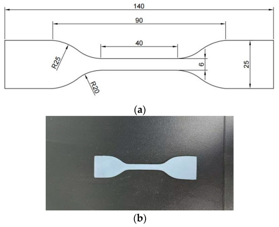
Figure 1.
Specimen size and photos. (a) Specimen size (mm). (b) Specimen.
- (2)
- Experiment analysis method
The nominal stress-strain method is usually used to analyze the test data in the uniaxial tensile test. The stress and strain are calculated according to the following formula:
where is the engineering stress (nominal stress), is the force, is the cross-sectional area, is the thickness, is the width, is the nominal strain, is the measured length elongation, and is the measurement length.
The above formulas do not consider the change in the cross-section and the total length of the specimen during the tensile process when calculating the stress and strain. However, in the actual tensile process, many hyperelastic materials will have a certain necking phenomenon during large deformation. Therefore, on this basis, considering the actual situation, the true stress-strain is calculated by the following formula:
where is the true stress and is the true strain.
- (3)
- Test result analysis
Uniaxial tensile tests were carried out on the specimens, as shown in Figure 2. The axial force and displacement of the specimens from the beginning of tension to fracture were recorded by the testing machine. The maximum tension and maximum displacement of the two specimens are shown in Table 1.
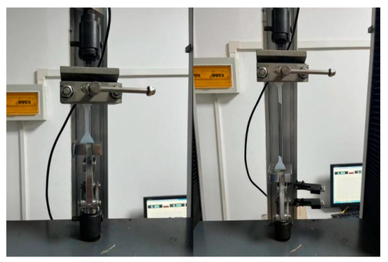
Figure 2.
Uniaxial tensile test of modified polydimethylsiloxane material.

Table 1.
Uniaxial tensile test results.
From the Formulas (1)–(3), the nominal stress-strain curve of the modified polydimethylsiloxane membrane can be obtained, as shown in Figure 3a. Similarly, the nominal stress and strain can be converted to the true stress and strain by Equations (4) and (5), so as to obtain the true stress-true strain curve of the modified polydimethylsiloxane membrane, as shown in Figure 3b.
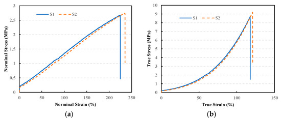
Figure 3.
Stress-strain curve. (a) Nominal stress-strain curve. (b) True stress-strain curve.
The stress-strain curves of the S1 and S2 samples are relatively close; therefore, the average value of the two sets of data can be used as the tensile properties of the modified polydimethylsiloxane membrane. In addition, the nominal stress-strain curve of the modified polydimethylsiloxane membrane is approximately a straight line before breaking, which is judged as a linear-elastic constitutive relationship. However, the true stress-strain curve is concave before breaking and shows strong non-linear deformation characteristics. According to Figure 3, the average fracture strength, fracture elongation, and elastic modulus of the modified polydimethylsiloxane membrane calculated by the nominal stress-strain method and the true stress-strain method can be obtained, as shown in Table 2. As shown, the mechanical properties obtained by the real stress-strain method are significantly different from those obtained by the nominal stress-strain method, which does not consider the change in the cross-section and total length of the specimen. The fracture strength obtained by the real stress-strain method is 3.3 times that obtained by the nominal stress-strain method. Secondly, the modified polydimethylsiloxane is a typical super-elastic material, and its true fracture elongation is about 118.98%.
Table 2.
Material properties obtained by two analysis methods.
2.2. Identification of Constitutive Model
The stress–strain relationship of hyperelastic materials is expressed by the strain potential energy function:
where is the second Piola–Kirchhoff stress, is the Green strain, and is the strain potential energy function.
There are mainly nine kinds of strain potential energy function forms in ABAQUS: Arruda–Boyce form, Marlow form, Mooney–Rivlin form, neo–Hookean form, Ogden form, Polynomina (polynomial) form, Reduced Polynominal (simplified polynomial) form, Yeoh form, and VanderWaals form. Users can provide material test data, and the ABAQUS software (2019) can match the optimal strain potential energy. According to the test data of the direct tensile test of the modified polydimethylsiloxane membrane, the optimal strain potential energy function form is the reduced polynominal form. The form of the reduced polynominal strain energy potential is as follows:
where is the strain energy per unit of reference volume, is a material parameter, and are temperature-dependent material parameters, and is the first deviatoric strain invariant defined as follows:
where the deviatoric stretches , is the total volume ratio, and denote the principal stretches. is the elastic volume ratio as defined as follows:
where is the thermal volume ratio, defined as follows:
where is the linear thermal expansion strain that is obtained from the temperature and the isotropic thermal expansion coefficient.
The initial shear modulus and bulk modulus are given by the following equations:
After the ABAQUS software evaluation, the reduced polynominal form with a strain potential energy order of is determined as the optimal strain potential energy form, referred to as RP-N2, and the relevant parameters are automatically fitted, which are , , , . The constitutive relation of the modified polydimethylsiloxane in the form of RP-N2 strain potential energy is shown in Figure 4.
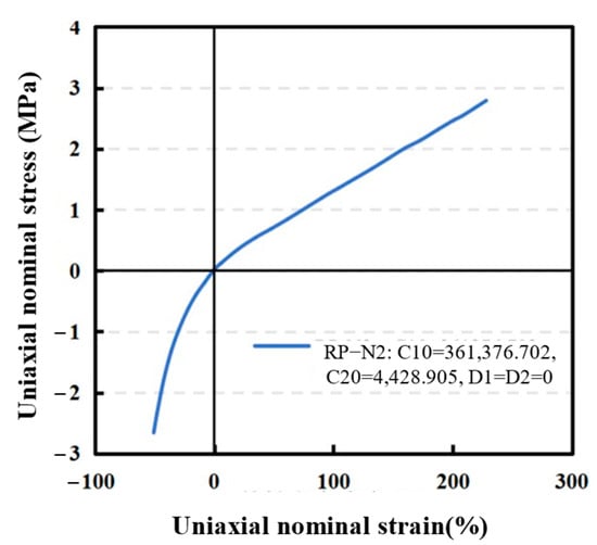
Figure 4.
RP-N2 hyperelastic constitutive relation.
2.3. Numerical Simulation of Tensile Test
In order to verify the rationality of constitutive model and parameters of the modified polydimethylsiloxane, two sets of numerical simulations corresponding to the nominal stress-strain method and the true stress-strain method were further carried out. The two sets of numerical simulation specimens are consistent with the actual specimens. The specific dimensions are shown in Figure 1, and the analysis settings of the two sets of numerical simulations are shown in Table 3.
Table 3.
Analysis settings of numerical simulations.
The meshing and load boundary conditions of the two sets of numerical simulations are the same. As shown in Figure 5, there are 4650 quadrilateral plane stress elements, and the grids are refined in the middle. The boundary conditions are achieved by applying a completely fixed constraint at the lower end of the specimen. The displacement of 0.2 m is applied on the RP-1 reference point coupled to the upper surface of the specimen, and the displacement amplitude is set to gradually increase with the increment step.
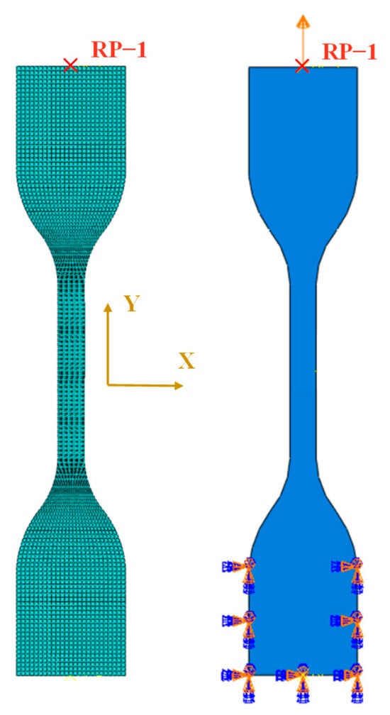
Figure 5.
Grid division and load boundary conditions.
The nominal stress-strain curves and the true stress-strain curves obtained from the two sets of numerical simulations and experimental tests are shown in Figure 6. The root mean square error RMSE, mean absolute error MAE, and correlation coefficient R2 were used to evaluate the simulation effect of the two models on the modified polydimethylsiloxane material. The calculation results are shown in Table 4. As shown, both the nominal stress-strain analysis method and the true stress-strain analysis method have good simulation results; therefore it is feasible to use the two methods for analysis, which can effectively simulate the modified polydimethylsiloxane impermeable coating material. However, in comparison, the root mean square error and mean absolute error of the results obtained by the hyperelastic material constitutive model are smaller, the correlation coefficient is larger, and the simulation effect is better. Therefore, the subsequent numerical simulation directly uses the hyperelastic material attribute parameters.
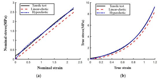
Figure 6.
Stress-strain curves obtained by two numerical simulation methods. (a) Nominal stress-strain curve. (b) True stress-strain curve.
Table 4.
Evaluation and comparison of two constitutive models.
3. Cracking Simulation and Cracking Damage Range Analysis
After the concrete lining cracks in the tunnel, the modified polydimethylsiloxane coating may be punctured under the action of internal water pressure. Therefore, it is necessary to explore the width and depth of cracks in the tunnel’s lining under the action of internal water pressure, before simulating the stress state of modified polydimethylsiloxane.
In the simulation, in order to simulate the cracking effect of the tunnel, 24 sets of radial cohesive-element are embedded on the basis of the conventional finite element model, that is, the radial cohesive-element is arranged at intervals of 15° in the circumferential direction of the tunnel. The cohesive element can be used to study the whole process of crack initiation and propagation. It mainly simulates structural cracking by defining the damage initiation criterion and damage evolution process. In order to achieve the cracking effect, it is necessary to input damage initiation stress-strain, fracture strain, and other related parameters to control the fracture of the element and the deletion of the failure element.
3.1. Finite Element Model
The finite element analysis software ABAQUS is used to model the two-dimensional structure of a tunnel. The size of the tunnel section is shown in Figure 7. The solid structure was meshed with the four-node plane strain quadrilateral element, CPE4R.
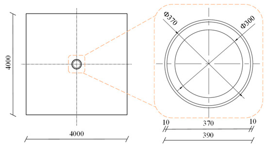
Figure 7.
Tunnel profile in the simulation (unit: cm).
The element mesh was refined in the surrounding area of the tunnel. The element size is controlled within 0.05 m in the area of the composite lining, and the element mesh in the surrounding rock gradually becomes sparse from inside to outside. In order to improve the simulation accuracy of crack length, the tunnel’s shotcrete was divided into two layers of elements, and the secondary lining is divided into seven layers of elements. The whole model takes the x-axis direction as the horizontal direction and the y-axis direction as the vertical direction. The number of nodes is 32,736, and the number of elements is 32,603. The finite element model is shown in Figure 8. To compare and analyze the cracking effect of the cohesive element, two finite element models with and without cohesive elements were established. For the finite element model with cohesive elements, the cohesive elements with a thickness of 1 mm were established every 15° along the circumferential direction of the tunnel. The cohesive elements penetrate from the lining surface to the boundary of the finite element model. The mesh of the finite element model without cohesive elements is unified with the cohesive model so that the influence of mesh is excluded in the comparison of subsequent simulation results.
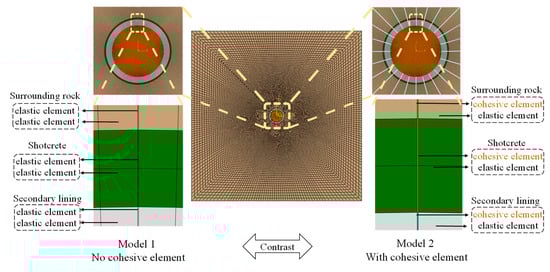
Figure 8.
Two-dimensional finite element model of the tunnel.
The material parameters of rock mass refer to the engineering geological report of Chuosijia Hydropower Station, and the surrounding rock of its diversion tunnel was mainly identified as the class III rock mass. After the excavation of the tunnel, C25 shotcrete was sprayed with a thickness of 10 cm. Subsequently, the C30 secondary lining was poured, and the lining thickness was 35 cm. The mechanical parameters of the surrounding rock, shotcrete, and secondary lining concrete are shown in Table 5.
Table 5.
Mechanical parameters of rock and concrete materials.
The cohesive elements inserted in the model can be divided into three types: cohesive elements that simulate the fracture of surrounding rock, shotcrete, and secondary lining concrete, respectively named Cohesive-ROCK, Cohesive-C25, and Cohesive-C30. The cohesive element properties mainly include normal stiffness, tangential stiffness, crack initiation stress under the quads damage criterion (including normal crack initiation stress and tangential crack initiation stress), and the damage evolution fracture energy parameters using the energy form of BK criterion (including normal fracture energy and tangential fracture energy). The parameters used in the simulation are shown in Table 6.
Table 6.
Material parameters of cohesive element.
The simulated tunnel has a buried depth of 100 m, and its internal water pressure increases from 1 MPa to 5 MPa to investigate the fracture effect of the cohesive element. The fracture effect of the horizontal cohesive element on the right side of the tunnel under the action of water pressure from 1 MPa to 5 MPa is shown in Figure 9. As shown, as the internal water pressure gradually increases, the cohesive element gradually cracks and simulates the fracture effect very well.
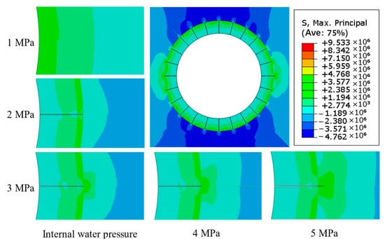
Figure 9.
Fracture effect of cohesive element at the buried depth of 100.
The displacement distribution and stress distribution of the tunnel with a buried depth of 100 m under the condition of 5 MPa water pressure are shown in Figure 10 and Figure 11. As shown, the maximum principal stresses of the composite lining structure without and with cohesive elements are 6.852 MPa and 4.631 MPa, respectively, both of which are tensile stress (i.e., tensile is positive, and pressure is negative). The maximum principal stresses of the surrounding rock without and with cohesive elements are 0.836 MPa and 4.866 MPa, respectively. After considering the cracking effect of concrete and surrounding rock, the tensile stress borne by the composite lining structure decreases, while the tensile stress borne by the surrounding rock increases. This shows that the introduction of cohesive element can better simulate the surrounding rock-lining bearing system after lining cracking. After the cohesive element of the lining structure is damaged and broken, the stress of the surrounding rock-lining structure is redistributed so that the surrounding rock plays a greater bearing role, which is more in line with the bearing response mechanism of the actual engineering.
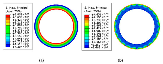
Figure 10.
The maximum principal stress of the composite lining at the buried depth of 100 m. (a) Without cohesive element. (b) With cohesive element.
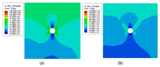
Figure 11.
The maximum principal stress of the surrounding rock at the buried depth of 100 m. (a) Without cohesive element. (b) With cohesive element.
3.2. Analysis of Tunnel Cracking Width
Under the action of internal water pressure, the lining may produce cracks. When the cracks occur, the modified polydimethylsiloxane coating may be pressed into the cracks under the action of internal water pressure. Then, the modified polydimethylsiloxane coating is cut by the edge of the cracks so that the modified polydimethylsiloxane coating loses its waterproof effect. Therefore, the crack width of the composite lining structure is calculated and analyzed.
Three hundred and thirty sets of conditions including different in situ stress and internal water pressure were set up for comparative analysis. Among them, the simulated maximum vertical in situ stress is 51.94 MPa, and the maximum horizontal in situ stress is 72.716 MPa. The distribution of horizontal stress and vertical stress is shown in Figure 12. The range of internal water pressure is 1 MPa~10 MPa, and the internal water pressure of 153 groups of conditions is set to 5 MPa.
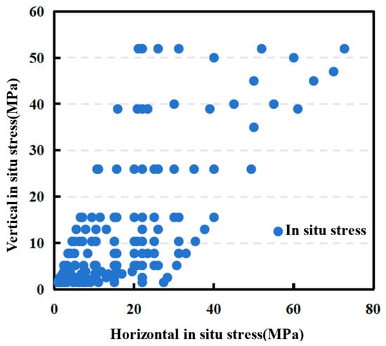
Figure 12.
The simulated range of in situ stress.
When the water pressure is within 5 MPa, the maximum crack width of lining structure under different in situ stress conditions is shown in Figure 13. It shows that the influence of in situ stress on the crack width of the lining is affected by both the buried depth of the tunnel and the horizontal stress. The maximum crack width shows an overall downward trend with the increase in buried depth, indicating that the greater the buried depth of the tunnel, the more stable the lining structure is, and the less prone to crack damage.
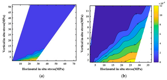
Figure 13.
Isoline cloud diagram of maximum cracking width of lining structure. (a) Overall graph. (b) Local enlarged graph.
The influence of horizontal stress on the maximum crack width of lining structure is shown in Figure 14. As shown, as the horizontal stress increases, the maximum crack width decreases firstly and then increases under the same buried depth. The horizontal stress of the inflection point is similar to the vertical stress. In other words, when the lateral pressure coefficient is less than 1, the maximum crack width decreases with the increase in the lateral pressure coefficient; when the lateral pressure coefficient is greater than 1, the maximum crack width increases with the increase in the lateral pressure coefficient. Therefore, when the lateral pressure coefficient is smaller or larger, the shallower the buried depth of the tunnel is, the more likely it is to crack.
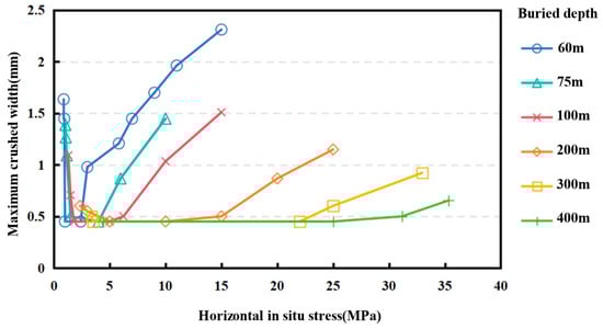
Figure 14.
The influence of horizontal stress on the maximum crack width of lining structure.
4. Failure of Modified Polydimethylsiloxane Impermeable Coating Under Internal Water Pressure
The localized annular composite lining structure with the impermeable coating and cracks in the tunnel is simplified into rectangular lining and impermeable membrane with cracks, so as to investigate the crack resistance of the modified polydimethylsiloxane impermeable coating. The simplified finite element model is shown in Figure 15.

Figure 15.
Simplified finite element model of the modified polydimethylsiloxane impermeable coating.
In the simulation, the parameters of lining are the parameters of C30 concrete, and the modified polydimethylsiloxane adopts the hyperelastic material parameters shown in Table 4. The true fracture elongation of the test is 118.98%, which is the failure criterion of the modified polydimethylsiloxane coating. When the true strain of the modified polydimethylsiloxane coating reaches 118.98%, the impermeable coating suffers tensile failure.
4.1. Influence of the Internal Water Pressure
To control a single variable, the thickness of the impermeable coating is unified to 0.5 mm, and the crack width of the concrete is initially 0.142 mm. Then, the water pressure on the impermeable coating is set within 1~10 MPa. The strain of the impermeable coating with a thickness of 0.5 mm under the internal water pressure of 1 MPa, 2 MPa, 3 MPa, 4 MPa, 5 MPa, 6 MPa, 7 MPa, 8 MPa, 9 MPa, and 10 MPa is simulated, respectively. Figure 16 shows the numerical simulation results under the water pressure of 5 MPa. As shown, the maximum true principal strain of the modified polydimethylsiloxane coating is 75.58%, which does not exceed its strain failure criterion of 118.98%, indicating that the modified polydimethylsiloxane coating will not crack under this working condition.
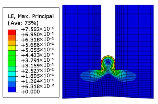
Figure 16.
The strain of the modified polydimethylsiloxane coating under the water pressure of 5 MPa.
The variation of the maximum principal strain with the internal water pressure is shown in Figure 17. As shown, with the increase in internal water pressure, the maximum true principal strain of the modified polydimethylsiloxane coating gradually increases. Therefore, under the same conditions of the thickness of the impermeable coating and the cracking width of the lining structure, the greater the internal water pressure of the tunnel, the more likely the tunnel impermeable coating is to be damaged.
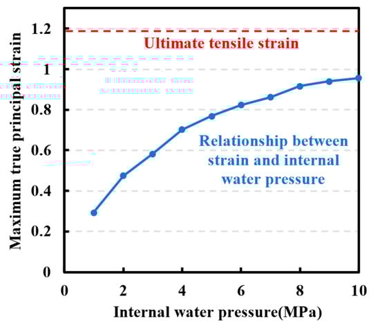
Figure 17.
The influence of water pressure on the maximum true principal strain of waterproof coating.
4.2. Influence of the Coating’s Thickness
To further explore the influence of the thickness of the impermeable coating on its tensile crack resistance, the coating’s thickness is also controlled for sensitivity analysis, and the internal water pressure is uniformly set to 5 MPa. In addition, since the thickness of the impermeable coating is a relative size compared to the crack width, the thickness-to-width ratio α is introduced. If the thickness of the impermeable coating is h and the crack width is w0, then α = h/w0. In the simulation, the coating’s thickness is set within the range of 0.008 mm~0.6 mm, the crack width of the lining structure is fixed to 0.142 mm, and the corresponding thickness-to-width ratio has a range of 0.056~4.225. The influence of the thickness-to-width ratio of the membrane on the maximum true principal strain of the impermeable coating is shown in Figure 18. As shown, the larger the ratio of thickness-to-width, the smaller the maximum true principal strain of the impermeable coating, and the less likely it is to be damaged. In other words, if the crack width is constant, the thicker the modified polydimethylsiloxane impermeable coating is sprayed, the better the tensile crack resistance of the modified polydimethylsiloxane impermeable coating.
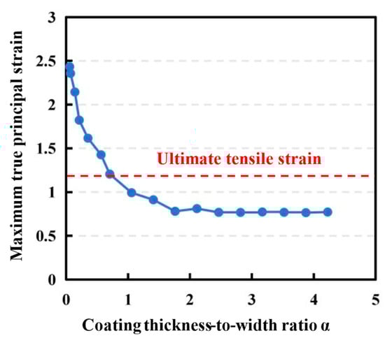
Figure 18.
The effect of thickness-to-width ratio on the maximum true principal strain of impermeable coating.
5. Discussion on the Thickness of Impermeable Coating
Although a thicker layer of the modified polydimethylsiloxane is required to improve its crack resistance, it would also increase the cost. To reduce the cost on the basis of ensuring the engineering safety, it is necessary to solve the critical thickness-to-width ratio under different internal water pressure and coating thickness conditions. Therefore, 156 sets of numerical simulations were carried out to analyze the maximum true principal strain of the modified polydimethylsiloxane impermeable coating under different conditions. The analysis results are shown in Figure 19.
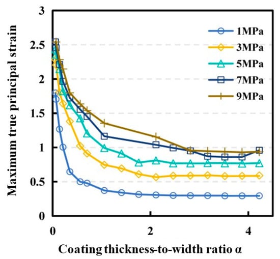
Figure 19.
Effect of thickness-to-width ratio on the maximum true principal strain of impermeable coating under different internal water pressure.
The critical coating thickness-to-width ratios that control the maximum true principal strain of the coating within 118.98% are listed in Table 7. If the designed water pressure of a diversion tunnel is known, the corresponding critical coating thickness-to-width ratio can be obtained according to the table. Further analysis of the maximum cracking width of the tunnel lining structure under the designed internal water pressure can be substituted to obtain the critical coating thickness, which can be used as the recommended thickness of the modified polydimethylsiloxane coating. At the same time, the determination of the coating’s thickness according to different internal water pressure conditions is conducive to cost savings. For example, the cost of film thickness with internal water pressure of 3 MPa is about 1.5 times that of film thickness with internal water pressure of 2 MPa.
Table 7.
Critical coating thickness-to-width ratio under different internal water pressure conditions.
The proposed modified polydimethylsiloxane coating demonstrates significant engineering applicability for high-pressure water conveyance tunnels, particularly in pumped storage power stations. With a true fracture elongation of 118.98%, the modified polydimethylsiloxane coating effectively accommodates concrete lining deformations while maintaining impermeability. The critical thickness-to-width ratios provided in Table 7 enable engineers to optimize the coating’s thickness based on site-specific crack widths (e.g., 0.731 mm/mm for 5 MPa internal pressure). In contrast to rigid epoxy coatings prone to interfacial debonding, the hyperelastic polydimethylsiloxane minimizes the stress concentration at crack tips. However, field applications, such as the preliminary implementation in Sichuan pumped storage projects, should be carried out to validate its adhesion stability under cyclic hydraulic loading. In addition, long-term durability under coupled thermo-hydro-mechanical conditions remains to be field-verified, necessitating embedded strain sensors for operational health monitoring.
6. Conclusions
In this paper, the uniaxial tensile test of modified polydimethylsiloxane material was carried out, and the hyperelastic constitutive model of modified polydimethylsiloxane material was established. Based on the constitutive model, a two-dimensional finite element model is established in combination with the cohesive element to simulate the tensile failure of the composite lining structure and the surrounding rock. A simplified finite element model of the composite lining is established to study the crack resistance of the modified polydimethylsiloxane impermeable coating under internal water pressure. The main conclusions of this paper are as follows:
- (1)
- The modified polydimethylsiloxane exhibits exceptional hyperelastic behavior with a true fracture elongation of 118.98%. The simplified polynomial hyperelastic constitutive model (RP-N2) accurately captures its non-linear mechanical response, achieving a correlation coefficient (R2) of 0.999 with experimental data. This behavior enables the coating to accommodate large deformations in cracked concrete linings while maintaining impermeability. Furthermore, the RP-N2 model’s computational efficiency enables rapid structural assessments, maintaining 99% accuracy in strain prediction.
- (2)
- The crack width of lining structure decreases with the increase in buried depth, and the crack width gradually maintains invariance after reaching a certain buried depth. When the lateral pressure coefficient is less than 1, the maximum crack width decreases with the increase in the lateral pressure coefficient; when the lateral pressure coefficient is greater than 1, the maximum crack width increases with the increase in the lateral pressure coefficient.
- (3)
- The derived critical thickness-to-width ratios provide a quantifiable design framework. According to different internal water pressure conditions, a set of thickness-to-width ratios are suggested to determine the thickness of the modified polydimethylsiloxane impermeable coating in tunnel engineering. The proposed methodology addresses practical challenges in ultra-high-pressure tunnel design. By correlating the polydimethylsiloxane thickness with crack width and lateral pressure coefficients, engineers can optimize coating specifications for specific geological and hydraulic conditions.
Author Contributions
Y.X. provided the original idea and wrote the original manuscript. H.X. provided engineering guidance and verified the feasibility of the method. J.W. reviewed and edited the manuscript. X.Y. investigated and provided engineering data. L.Q. analyzed the results of this method. All authors have read and agreed to the published version of the manuscript.
Funding
This study was financially supported by the Natural Science Foundation of Sichuan Province, China (No. 2024NSFSC0836). We acknowledge the aforementioned supports.
Institutional Review Board Statement
Not applicable.
Informed Consent Statement
Not applicable.
Data Availability Statement
The datasets used in the current study are available from the corresponding author upon reasonable request.
Acknowledgments
This study was financially supported by the Natural Science Foundation of Sichuan Province, China (No. 2024NSFSC0836). We acknowledge the aforementioned supports. Special thanks to Baobao Tan for the support of this study.
Conflicts of Interest
Authors Yong Xia and Xingyi Yang were employed by the company POWERCHINA Chengdu Engineering Corporation Limited. The remaining authors declare that the research was conducted in the absence of any commercial or financial relationships that could be construed as a potential conflict of interest.
References
- Quaranta, E.; Boes, M.R.; Hunt, D.J.; Szabò, S.; Tattini, J.; Pistocchi, A. Considerations on the existing capacity and future potential for energy storage in the European Union’s hydropower reservoirs and pumped-storage hydropower. J. Energy Storage 2024, 104, 114431. [Google Scholar] [CrossRef]
- Hunt, D.J.; Silva, V.C.; Fonseca, E.; Freitas, M.A.V.; Brandão, R. Role of pumped hydro storage plants for flood control. J. Energy Storage 2024, 104, 114496. [Google Scholar] [CrossRef]
- Liu, J. Study on Mechanical Properties of Waterproof Film and Interface Between Layers of Sprayed Waterproof Lining Structure in Tunnel. Master’s Thesis, Southwest Jiaotong University, Chengdu, China, 2021. (In Chinese). [Google Scholar]
- Zeng, X. Study on hydraulic fracturing mechanism under high internal water pressure based on discrete element method. Railw. Constr. Technol. 2022, 6–9+54. (In Chinese) [Google Scholar]
- Yasuda, M.; Watanabe, S. How to Avoid Severe Incidents at Pumped Storage Power Plants. IOP Conf. Ser. Earth Environ. Sci. 2016, 49, 112002. [Google Scholar] [CrossRef]
- Thomas, A.; de Battista, N.; Elshafie, M.; Viggiani, G. Back-analysis of sprayed concrete lined (SCL) tunnel junctions at Liverpool Street Crossrail station. Tunn. Undergr. Space Technol. 2023, 141, 105391. [Google Scholar] [CrossRef]
- Pelz, U.; Karlovšek, J. Spray-applied waterproofing membranes in tunnelling: A construction perspective. Tunn. Undergr. Space Technol. Inc. Trenchless Technol. Res. 2023, 142, 105409. [Google Scholar] [CrossRef]
- He, B.; Jiang, Y.; Zhao, J.; Liu, J.; Pei, H. Study on the influence of different waterproof film interface parameters on the mechanical properties of spray film waterproof lining structure. Highw. Traffic Technol. 2023, 39, 161–168. (In Chinese) [Google Scholar]
- Bloodworth, A.; Jiang, S. Numerical analysis and capacity evaluation of composite sprayed concrete lined tunnels. Undergr. Space 2018, 3, 87–108. [Google Scholar] [CrossRef]
- Lee, K.; Kim, D.; Chang, S.-H.; Choi, S.-W.; Park, B.; Lee, C. Numerical approach to assessing the contact characteristics of a polymer-based waterproof membrane. Tunn. Undergr. Space Technol. Inc. Trenchless Technol. Res. 2018, 79, 242–249. [Google Scholar] [CrossRef]
- Johnson, R.P.; Swallow, F.E.; Psomas, S. Structural properties and durability of a sprayed waterproofing membrane for tunnels. Tunn. Undergr. Space Technol. Inc. Trenchless Technol. Res. 2016, 60, 41–48. [Google Scholar] [CrossRef]
- Vogel, F.; Sovják, R.; Pešková, Š. Static response of double shell concrete lining with a spray-applied waterproofing membrane. Tunn. Undergr. Space Technol. Inc. Trenchless Technol. Res. 2017, 68, 106–112. [Google Scholar] [CrossRef]
- Su, J.; Alan, B. Determination of the stress-strain demand curve of the sprayed waterproofing membrane interface in composite SCL tunnels. Tunn. Undergr. Space Technol. Inc. Trenchless Technol. Res. 2023, 142, 105408. [Google Scholar] [CrossRef]
- Liang, W. Durability of Road and Bridge Concrete and Spray-Coating Waterproof Material. RCMA 2021, 31, 227–235. [Google Scholar] [CrossRef]
- Baniasadi, H.; Äkräs, L.; Madani, Z.; Silvenius, F.; Fazeli, M.; Lipponen, S.; Vapaavuori, J.; Seppälä, J. Development and characterization of polylactic acid/starch biocomposites—From melt blending to preliminary life cycle assessment. Int. J. Biol. Macromol. 2024, 279, 135173. [Google Scholar] [CrossRef]
- Nuge, T.; Fazeli, M.; Baniasadi, H. Elucidating the enduring transformations in cellulose-based carbon nanofibers through prolonged isothermal treatment. Int. J. Biol. Macromol. 2024, 275, 133480. [Google Scholar] [CrossRef] [PubMed]
- Zhang, H.; Tang, P.; Tang, Y.; Yang, K.; Wang, Q. MXene-Functionalized Light-Induced Antimicrobial and Waterproof Polyacrylate Coating for Cementitious Materials Protection. Polymers 2023, 15, 2076. [Google Scholar] [CrossRef]
- Jiang, S.; Bloodworth, A. Simulating composite behavior in SCL tunnels with sprayed waterproofing membrane interface: A state-of-the-art review. Eng. Struct. 2019, 191, 698–710. [Google Scholar]
- Sarva, S.S.; Deschanel, S.; Boyce, M.C.; Chen, W. Stress–strain behavior of a polyurea and a polyurethane from low to high strain rates. Polymer 2007, 48, 2208–2213. [Google Scholar] [CrossRef]
- Miao, Y.; Zhang, H.; He, H.; Deng, Q. Mechanical behaviors and equivalent configuration of a polyurea under wide strain rate range. Compos. Struct. 2019, 222, 110923. [Google Scholar] [CrossRef]
- Chen, Y.; Guo, H.; Sun, M.; Lv, X. Tensile Mechanical Properties and Dynamic Constitutive Model of Polyurea Elastomer under Different Strain Rates. Polymers 2022, 14, 3579. [Google Scholar] [CrossRef]
- Qi, H.J.; Boyce, M.C. Constitutive model for stretch-induced softening of the stress-stretch behavior of elastomeric materials. J. Mech. Phys. Solids 2004, 52, 2187–2205. [Google Scholar] [CrossRef]
- Shim, J.; Mohr, D. Using split Hopkinson pressure bars to perform large strain compression tests on polyurea at low, intermediate and high strain rates. Int. J. Impact Eng. 2009, 36, 1116–1127. [Google Scholar] [CrossRef]
- Jabbar, M.; Adnan, M.; Shaker, K.; Abdullah, T.; Nawab, Y.; Hussain, R.; Malik, A.U. Strength and durability that last—Mechanical properties of polyurea and polyurethane coated composites. Polym. Compos. 2023, 44, 4324–4335. [Google Scholar] [CrossRef]
- Cui, J.; Shi, Y.; Zhang, X.; Huang, W.; Ma, M. Experimental study on the tension and puncture behavior of spray polyurea at high strain rates. Polym. Test. 2021, 93, 106863. [Google Scholar] [CrossRef]
- Liu, Y.; Shao, Y.; Wang, Y.; Wang, J. An abrasion-resistant, photothermal, superhydrophobic anti-icing coating prepared by polysiloxane-modified carbon nanotubes and fluorine-silicone resin. Colloids Surf. A Physicochem. Eng. Asp. 2022, 648, 129335. [Google Scholar] [CrossRef]
- Tan, B.; Qu, L.; Xia, Y.; Yang, X.; Su, B.; Wu, J.; Xiao, M. Experimental Study on Improving the Impermeability of Concrete under High-Pressure Water Environments Using a Polymer Coating. Appl. Sci. 2024, 14, 8507. [Google Scholar] [CrossRef]
- He, T.; He, Z.; Zhao, B. The Concrete Protective Project of Diversion Tunnel of Guangzhou Pumped Storage Power Station. Hydropower Pumped Storage 2017, 3, 87–90. (In Chinese) [Google Scholar]
- Li, B.; Zhang, J.; Liu, X.; Meng, T. Sealing and anti-seepage polyurea coating design method based on nonlinear FEM simulation. Eng. Comput. 2024, 41, 2289–2309. [Google Scholar] [CrossRef]
- Li, B.; Zhang, J.; Liu, X.; Meng, T. Investigation of a novel hydraulic tunnel composite lining with polyurea coating interlayer. Eng. Comput. 2024, 41, 1640–1671. [Google Scholar] [CrossRef]
Disclaimer/Publisher’s Note: The statements, opinions and data contained in all publications are solely those of the individual author(s) and contributor(s) and not of MDPI and/or the editor(s). MDPI and/or the editor(s) disclaim responsibility for any injury to people or property resulting from any ideas, methods, instructions or products referred to in the content. |
© 2025 by the authors. Licensee MDPI, Basel, Switzerland. This article is an open access article distributed under the terms and conditions of the Creative Commons Attribution (CC BY) license (https://creativecommons.org/licenses/by/4.0/).