Article

Optimization of Slotted Steel Plate Shear Walls Based on Adaptive Genetic Algorithm

School of Civil and Transportation Engineering, Guangdong University of Technology, Guangzhou 510006, China
*
Authors to whom correspondence should be addressed.
Appl. Sci. 2025, 15(11), 6088; https://doi.org/10.3390/app15116088
Submission received: 29 March 2025 / Revised: 2 May 2025 / Accepted: 5 May 2025 / Published: 28 May 2025

Abstract

This study develops an enhanced coding strategy with adaptive parameter adjustment mechanisms to address the premature convergence issue inherent in conventional genetic algorithms (GAs). An improved adaptive genetic algorithm (IAGA) is proposed for optimizing the slit pattern configurations of 16 steel-frame-slotted steel plate shear wall (SSPSW) systems. The methodology incorporates a real-time probability modulation of the crossover and mutation operations based on population diversity metrics. ABAQUS finite element software and PYTHON interactive analysis were systematically used to evaluate the mechanical performance of the optimized configurations, focusing on achieving an optimal ductility–stiffness balance under cyclic loading conditions. The numerical results demonstrate that the IAGA achieves faster convergence than standard GAs. A higher aspect ratio of the inter-slot column (l/b) or a smaller aspect ratio of the slot (b/t) leads to better ductility and lower stiffness. It is recommended that the configuration with connections on two sides of an SSPSW frame be adopted.

1. Introduction

A steel plate shear wall (SPSW) comprises three core components: embedded steel plates, vertical frame columns, and horizontal frame beams. The load-transfer mechanism of SPSWs resembles that of vertically cantilevered steel plate beams with fixed bases, where (1) the frame columns act as flanges resisting the axial forces, (2) the embedded steel plates serve as webs dissipating the shear stresses, and (3) the frame beams function as transverse stiffeners restricting out-of-plane deformations. As a lateral force-resisting system, SPSWs rely on diagonal tension field action to counteract the horizontal shear forces. Compared to reinforced concrete shear walls, SPSW structures exhibit superior performance characteristics, including a lighter self-weight, reduced seismic effects, a higher bearing capacity, and enhanced initial lateral stiffness, collectively contributing to their exceptional lateral resistance. To date, SPSWs have been successfully implemented in diverse engineering applications, for example, the Shin Nittetsu Building, located in Tokyo, Japan [1]; the Hyatt Regency Hotel in Dallas, Texas; and the Sylmar County Hospital in California [2].
Typical SPSW variants comprise conventional, stiffened, slotted, composite, and low-yield-point steel plate shear walls, among others [3]. A slotted steel plate shear wall (SSPSW), initially proposed by Hitaka and Matsui [4,5], exhibits a distinct deformation mechanism, where the bending deformation of the inter-slot columns dominates, while the shear deformation remains secondary. Energy dissipation primarily occurs through plastic hinge formation at the inter-slot column ends, enabling controlled steel plate yielding prior to beam–column joint failure, thereby preserving structural integrity. This configuration enhances ductility, mitigates strength degradation, and suppresses hysteresis curve pinching. A key advantage of SSPSWs lies in their tunable stiffness via parametric design optimization.
The current research on SSPSWs predominantly addresses the theoretical and experimental aspects. In their theoretical investigations, Hitaka and Matsui [4,5], Su [6], and Wang and He [7] developed stiffness and load-bearing capacity models for SSPSWs through experimental and numerical simulations, including modified formulations. Wang et al. [8,9] analytically derived the initial stiffness of bilateral-joined SSPSWs, while He et al. [10] established a methodology for estimating the shear strength and elastic stiffness. Regarding the seismic performance, Cortes and Liu [11,12], Lu et al. [13,14], Wang et al. [15], Hao et al. [16], Deng et al. [17], and Liang et al. [18] conducted cyclic loading tests to evaluate the stiffness evolution, strength degradation, and recentering behavior. Zhao et al. [19,20] systematically examined the effects of SSPSWs on the structural stiffness, shear capacity, ductility, energy dissipation, and out-of-plane buckling through comparative analyses. Slotted configuration studies by Lu et al. [13], Wang et al. [15], and Jacobsen et al. [21] quantified the influence of the slot parameters on the lateral stiffness, ultimate bearing capacity, and hysteretic response. Li et al. [22] comprehensively analyzed the hysteretic curves, load-bearing capacity, lateral stiffness, and energy dissipation coefficients across unstiffened, cross-stiffened, perforated, and slitted SPSW configurations. The emerging design innovations include edge stiffeners [23], inclined slots [24], and rhombic/non-uniform slot patterns [25,26]. Recent advancements have focused on hybrid SSPSW–frame systems, exemplified by prefabricated self-centering steel frames [27], buckling-restrained SSPSWs [28], and cold-formed steel shear walls with slitted sheathing [17]. The critical parameters governing the lateral stiffness and load capacity include the slot quantity and the inter-slot column width-to-height ratios and width-to-thickness ratios. Additional influential factors encompass the edge stiffener arrangements, corner instability mitigation, and bolt slippage control. Ensuring the optimal energy dissipation while maintaining structural reliability necessitates a rigorous slotted configuration design, underscoring the paramount importance of parametric rationalization for SSPSW performance enhancement.
Building upon this research framework, this study systematically investigates the critical parameters governing the mechanical behavior of SSPSWs. The methodology integrates an enhanced genetic algorithm (IGA) with ABAQUS FE simulations to conduct comprehensive performance evaluations. Specifically, the SSPSWs are optimized as seismic damping components, prioritizing ductility enhancement through slit pattern refinement. The research objectives encompass three key aspects: (1) the identification of high-performance slit geometries that balance stiffness and energy dissipation; (2) a comparative evaluation of the SSPSW variants with optimized slit configurations under cyclic loading; and (3) the development of design recommendations for practical SSPSW applications. This integrated approach enables a quantitative assessment of the ductility–stiffness tradeoffs while establishing reliable correlations between the slit parameters and structural performance metrics.

2. Design and Implementation of Adaptive Genetic Algorithm

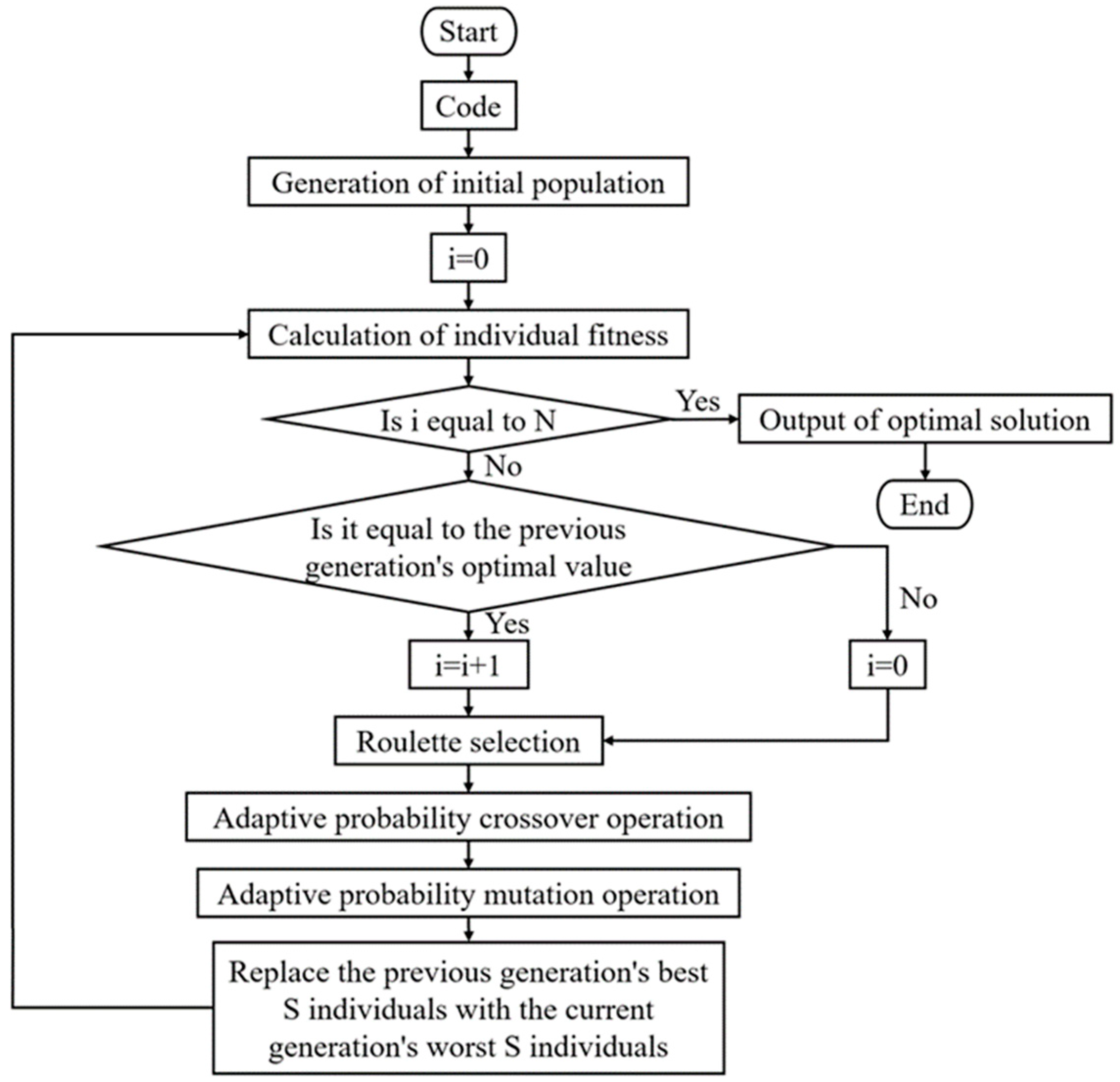
2.1. Design of Adaptive Genetic Algorithm

The canonical genetic algorithm (GA) framework comprises six fundamental operations: population initialization, fitness evaluation, selection, crossover, mutation, and generational replacement. The computational workflow initiates with the random generation of a population, where each individual solution is encoded as a chromosomal sequence. Subsequently, fitness values are calculated to quantify the solution quality. A selection operator identifies the high-fitness individuals as parental candidates for genetic recombination. The crossover operation probabilistically combines the parental chromosomes through simulated mating, generating novel offspring solutions. To enhance the population diversity, a mutation operator introduces stochastic gene-level modifications. The generational replacement phase then substitutes the parent population with the offspring cohort, completing one evolutionary cycle. This iterative process continues until the termination criteria are satisfied (e.g., maximum iterations or convergence of thresholds), progressively refining the solution quality. By emulating natural selection mechanisms, GAs effectively explore complex solution spaces. While standard GAs demonstrate multidisciplinary applicability, their inherent limitations include premature convergence to the local optima and computational inefficiency in the late-stage iterations. Contemporary research advancements have addressed these shortcomings through algorithmic enhancements, enabling broader theoretical and practical implementations across engineering domains [29,30].
This study proposes an improved adaptive genetic algorithm (IAGA) incorporating three key innovations: (1) dynamic probability adaptation, (2) an elitism strategy, and (3) convergence acceleration mechanisms, building upon the conventional genetic algorithm foundations. The validation through four benchmark function optimizations under identical computational conditions demonstrates that the IAGA effectively mitigates premature convergence, enhances the global search capability, and achieves accelerated convergence rates compared to standard genetic algorithms.
Compared to conventional adaptive probability strategies [31], the proposed enhancement introduces critical modifications to Equation (1), specifically incorporating a boundary condition when fmax = favg. This adaptation effectively prevents population homogeneity when implementing elitism strategies, thereby maintaining genetic diversity throughout the evolutionary iterations.
P c = k 1 , f m a x = f a v g k 2 f m a x f f m a x f a v g + k 3 , f , f a v g k 4 , f , = f a v g P m = k 5 , f m a x = f a v g k 6 f m a x f f m a x f a v g + k 7 , f f a v g k 8 , f = f a v g
In the equation, f′ represents the larger fitness value of the individuals to be crossed, fmax represents the maximum fitness value in the population, favg represents the average fitness value of the population, and f represents the fitness value of the mutated individual. The parameters k1, k2, k3, k4, k5, k6, k7, and k8 are all adaptive control parameters. The improved algorithm is shown in Figure 1.

2.2. Implementation of IAGA

As specialized seismic-resistant components, SSPSWs are typically integrated within structural frames, where stringent lateral stiffness requirements are relaxed. The inherent mechanical behavior of SSPSWs—whether configured with bilateral or quadrilateral connections—prioritizes ductility over lateral stiffness enhancement. Their fundamental functionality lies in stiffness modulation through slit parameterization while maintaining an exceptional energy dissipation capacity. Consequently, SSPSWs are predominantly employed as seismic dampers rather than primary lateral load-resisting elements. The optimization framework assumes that SSPSWs contribute minimally to global lateral stiffness while maximizing ductility performance. This ductility is quantified by the coefficient μ, defined in Equation (2), where higher μ values indicate superior deformation capacity.
m a x : μ = u m u y s . t . : s t i f f n e s s l i m i t
In the equation, um represents the ultimate displacement at the point of maximum load, and uy represents the yield displacement.
While the ductility coefficient μ is mathematically defined as the ratio of the ultimate displacement to yield displacement—establishing an inverse proportionality between μ and the yield displacement—high-ductility configurations typically exhibit a proportionally scaled yield and ultimate displacement magnitudes. Accordingly, this study employs the yield displacement as the fitness metric (Equation (3)). Concurrently, a stiffness contribution constraint mandates that the slotted steel plates provide at least 10% of the total system stiffness.
m a x : f i t n e s s = u y s . t . : s t i f f n e s s l i m i t
Notably, imposing stiffness thresholds as lower bounds proves counterproductive for SSPSW optimization. While enhanced ductility configurations typically exhibit reduced stiffness, the stiffness–ductility relationship manifests as a nonlinear interdependence rather than as a simplistic inverse proportionality. To holistically address this coupling, a penalty function (Equation (4)) is integrated into the fitness evaluation framework, enabling the simultaneous optimization of the stiffness and ductility objectives.
f i t n e s s = u y s t i f f n e s s l i m i t l i m i t × α
where α is a fixed coefficient used to adjust the penalty term to match with uy.
The proposed methodology integrates an ABAQUS finite element analysis with a PYTHON-implemented genetic algorithm for optimizing the SSPSW configurations. The optimization process is illustrated in Figure 2.

3. Optimization Analysis of SSPSWs

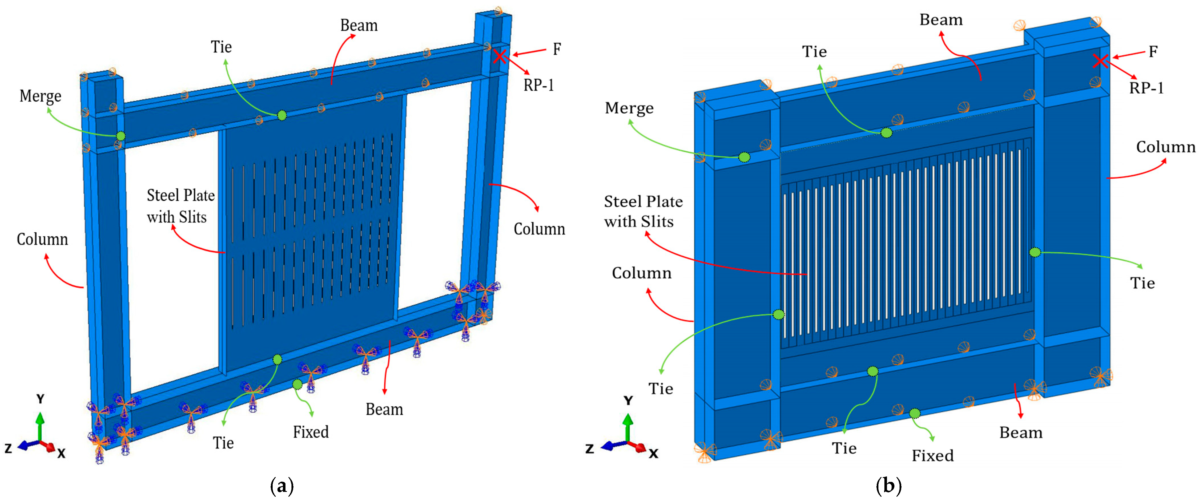
3.1. Experimental Design

The experimental steel frame–SSPSW model adopts the SF10S specimen configuration from Hitaka’s seminal work [1], with geometric parameters detailed in Figure 3. Key specimen specifications include the following: steel plate dimensions: 800 × 800 × 4.5 mm3 (SS400 steel grade); edge stiffener profile: 50 × 4.5 mm2; frame member sections: 100 × 100 × 6 × 8 mm4 (beams/columns); slot configuration: n = 17 slots arranged in m = 2 rows; inter-slot column dimensions: l = 235 mm, b = 42; and slot width: d = 3 mm. The test setup employs high-strength steel bar connections to reaction frame beams, incorporating lateral restraint devices to prevent out-of-plane displacements. Horizontal loading is applied via a hydraulic jack under displacement-controlled conditions, with inter-story displacement defined as the relative movement between base beam surfaces and specimen beam axes. The loading protocol initiates with a 0.25% drift cycle, followed by 0.5% incremental increases per cycle until achieving 5% drift capacity.

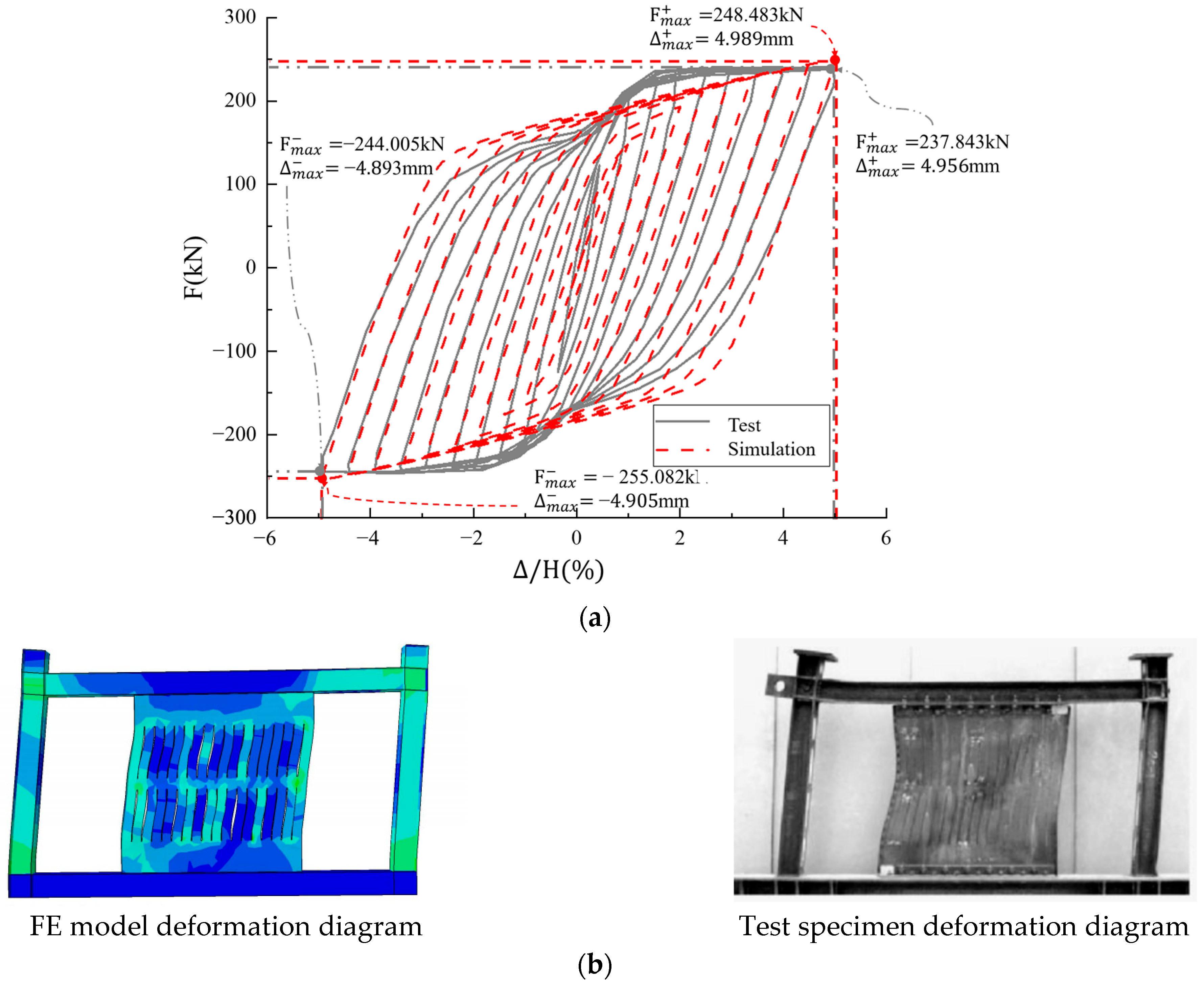
3.2. Modeling and Validation of the FE Model

The FE model in ABAQUS, as shown in Figure 4, incorporates SS400 steel material properties, defined as follows: elastic modulus, E 0 = 2.06 × 10 5   M P a ; yield stiffness,   E 1 = 0.01 E 0 ; Poisson’s ratio, μ = 0.3 , for steel SS400; yield strength σ y = 392   M P a ; and ultimate strength, σ u = 441   M P a . A tri-linear constitutive model is used to accurately simulate the steel’s material behavior, as shown in Figure 5. Von Mises yield criterion is adopted. An isotropic hardening model is used under monotonic loading conditions, and a kinematic hardening model considering the Bauschinger effect is applied for low-cycle cyclic loading. Four-node reduced-integration shell elements (S4Rs) employing hourglass control and hyperelastic formulation are used. A mesh size of 50 mm is adopted in the FE model. Boundary conditions enforce full fixity at column/beam bases and out-of-plane translational constraints at tops, while permitting free out-of-plane rotations at the frame apex. The assembly integrates beam–column nodal connections. For the bilateral-joined SSPSW, the slotted steel plates are tied to upper/lower beams. For the quadrilateral-joined SSPSW, all four edges of the slotted steel plate are tied to the beams and columns. Cyclic loading analysis executes 40 displacement-controlled steps, initiating at 0.25% inter-story drift with 0.5% incremental increases per cycle until 5% drift attainment, following the protocol in Figure 6.
Figure 7 compares experimental and finite FE-simulated hysteresis curves with deformation plots, demonstrating consistent cyclic behavior trends. The FE model predicts an ultimate load of 249 kN versus experimental measurements of 236 kN (5.2% deviation), while deformation patterns of slotted steel plates and frame components show close agreement with physical tests. These results validate the modeling approach’s capability to accurately replicate steel frame–SSPSW mechanical responses within acceptable error margins (≤5%), confirming its reliability for subsequent parametric optimization studies.

3.3. Optimization Scheme

The selected optimization parameters include slot quantity (n), inter-slot column height (l) and width (b), and slot width (d). Preliminary analyses identified plate thickness (t) as the dominant stiffness control variable, leading to its treatment as a fixed independent parameter. Frame aspect ratio effects are explicitly incorporated through bilateral (upper/lower beam only) and quadrilateral (beam–column) connection configurations. All beam and column sections maintain constant H-shaped profiles (H400 × 300 × 15 × 15 for beams, H500 × 350 × 15 × 15 for columns), with uniform 2400 mm column heights. Fourteen optimization models are established under the constraint of SSPSWs contributing 10% to total lateral stiffness, with initial stiffness amplified by 10% for design refinement. The comprehensive optimization framework is detailed in Table 1.

3.4. Optimization Results

For bilateral-joined SSPSW configurations (SPSW-TB12, SPSW-TF, SPSW-TB36, and SPSW-TB48) with varying frame aspect ratios, the optimization objective minimizes displacement at non-elastic dissipated energy (ALLPD), attaining target values of 8.55 mm, 9.13 mm, 10.23 mm, and 11.71 mm, respectively. Optimized parameters in Table 2 reveal minimal slotted plate width variation across frame aspect ratios. Ductility maximization necessitates full-frame utilization of slotted plates, with inter-slot column aspect ratios (l/b) exceeding critical thresholds to enhance deformability. However, increasing frame aspect ratios inversely reduces structural stiffness, constraining optimized plate widths within defined bounds. Consequently, SSPSW implementations in high-aspect-ratio frames require amplified stiffness contributions from slotted plates to compensate for inherent flexibility.
For SSPSW models with varying plate thicknesses (SPSW-TT8, SPSWTT10, SPSW-TF, and SPSW-TT14), optimization yields target displacements of 9.02 mm, 8.99 mm, 9.12 mm, and 8.97 mm, respectively. Table 2 summarizes optimized parameters, revealing a decreasing trend in inter-slot column width (b) with increasing plate thickness (t). Analysis demonstrates that thicker plates satisfy stiffness constraints more readily under equivalent requirements, inherently reducing slit configuration stiffness. Enhanced ductility correlates with higher inter-slot column aspect ratios (l/b) and lower width-to-thickness ratios (b/t), as evidenced by parametric optimization results. This inverse relationship between plate thickness and ductility underscores a critical design trade-off: while thicker plates improve stiffness by 12–15%, they reduce ductility capacity by 18–22%. Consequently, SSPSW design prioritizes thinner steel plates (t ≤ 12 mm) to balance stiffness demands with ductility performance requirements.
For quadrilateral-joined SSPSW configurations (SPSW-FB12, SPSW-FF, SPSW-FB36, and SPSW-FB48) with varying frame aspect ratios, optimization yields target displacements of 4.26 mm, 4.38 mm, 4.74 mm, and 5.28 mm, respectively. Optimized parameters in Table 2 demonstrate that lower-aspect-ratio frames with quadrilateral connections achieve 23–35% higher global stiffness compared to bilateral configurations, accompanied by increased slot widths. This enhanced stiffness performance necessitates proportionally higher stiffness contributions (18–22%) from slotted steel plates in quadrilateral-joined systems. In contrast to bilateral-joined configurations, quadrilateral implementations require prioritized optimization of slotted plate stiffness contributions to compensate for frame flexibility, particularly in high-aspect-ratio scenarios.
For quadrilateral-joined SSPSWs with varying plate thicknesses (SPSW-FT8, SPSW-FT10, SPSW-FF, and SPSW-FT14), optimization yields target displacements of 4.02 mm, 4.44 mm, 4.38 mm, and 4.20 mm, respectively. As detailed in Table 2, parametric trends mirror those of bilateral-joined configurations: increasing plate thickness inversely correlates with optimized ductility performance. This consistency across connection types validates the universal design principle of prioritizing thinner steel plates (t ≤ 12 mm) for slit configurations, as thickened plates detrimentally affect energy dissipation capacity while providing marginal stiffness gains (≤8%) in quadrilateral-joined systems.

4. Performance Analysis of SSPSWs

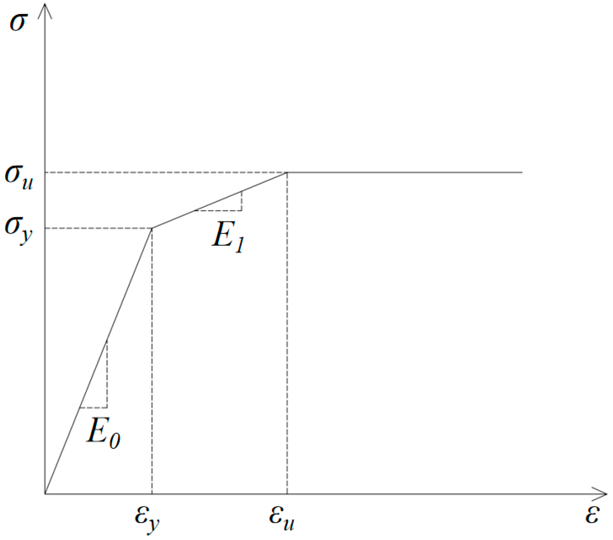
4.1. Indicator Calibration

The ductility coefficient μ, a critical metric for assessing the seismic deformation capacity of an SSPSW frame, is defined by Equation (5), where u m and u y denote the ultimate and yield displacements, respectively. The yield displacement determination follows the graphical method in Figure 8a: (1) construct a tangent through the origin intersecting the peak-load tangent at point A; (2) project vertically from A to intersect the load–displacement curve at B; (3) connect B to the origin, intersecting the peak-load tangent at C; (4) project vertically from C to the curve, defining yield point D. The displacement at D ( u y ) and the corresponding load ( F y ) establish the yield state, while the peak load displacement ( u m ) marks the ultimate deformation capacity.
μ = u m u y
The hysteresis energy dissipation capacity is quantified by the enclosed area of the hysteresis loop. The equivalent viscous damping ratio ζ , serving as the critical metric for assessing the energy dissipation performance, is calculated via Equation (6):
ζ = S A B C + A D C 2 π S E B O + O D F
where SABC+ADC represents the hysteresis loop area and S E B O + O D F denotes the combined triangular areas defined in Figure 8b.

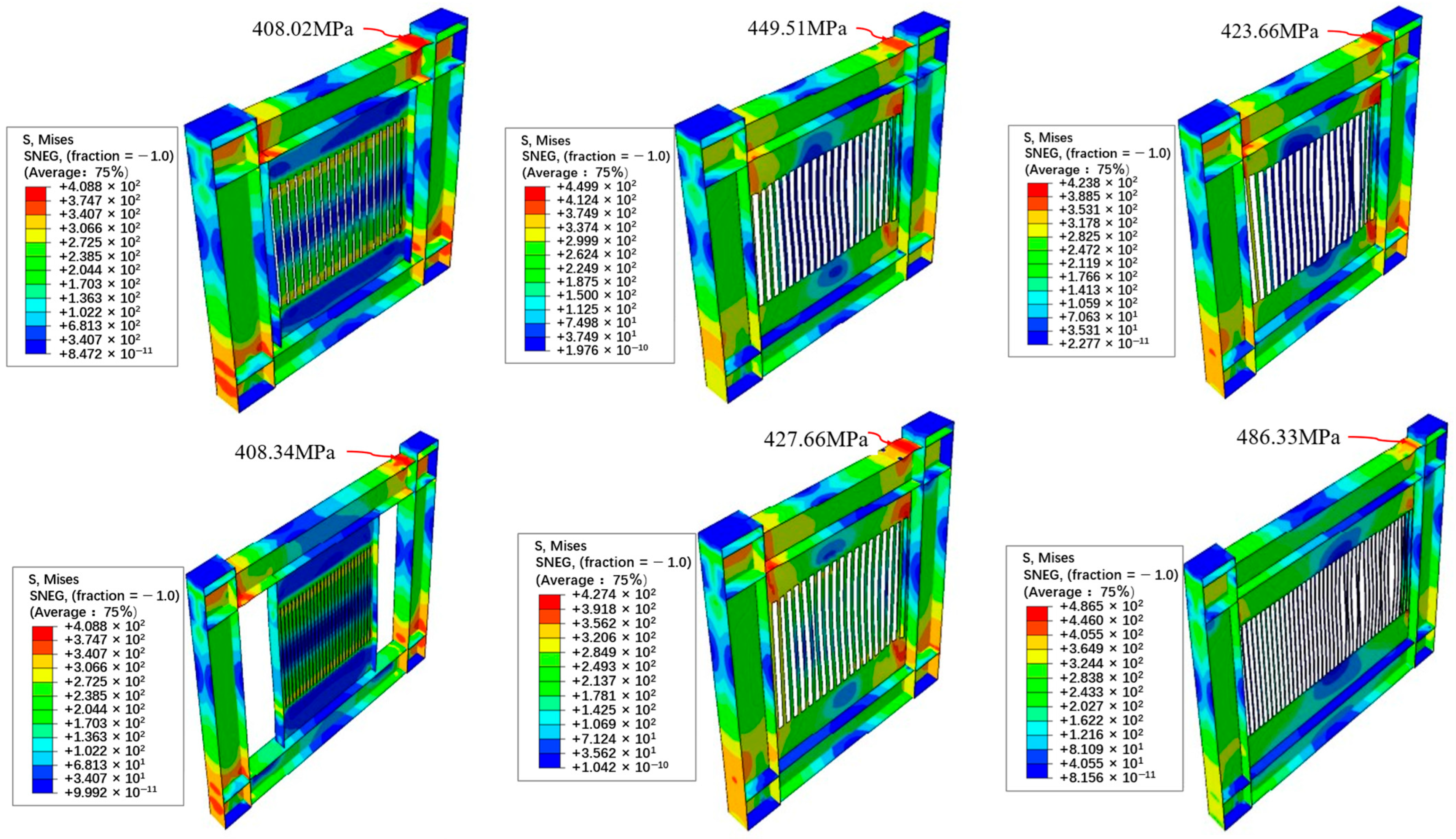
4.2. Elastic Buckling Performance

An elastic buckling analysis of the optimized SSPSWs was conducted via ABAQUS’s buckling module, revealing distinct failure modes across the connection types. The bilateral-joined configurations predominantly exhibited out-of-plane buckling in the steel plate’s right quadrant, involving 3–4 inter-slot columns (Figure 9a,b). The quadrilateral-joined systems demonstrated dual buckling mechanisms: Type I (SPSW-FF, SPSW-FT10, and SPSW-FT14) combined upper-left plate buckling with inter-slot-column lateral–torsional deformations (Figure 9c,d), while Type II (SPSW-FB12, SPSW-FB36, SPSW-FB48, and SPSW-FT8) manifested in-plane inter-slot-column flexural buckling (Figure 9e,f). As quantified in Table 3, the quadrilateral connections exhibited 18–25% lower critical buckling loads compared to their bilateral counterparts, necessitating the preferential adoption of bilateral configurations to ensure that yielding precedes instability.

4.3. Monotonic Loading Mechanical Performance

The bilateral-joined SSPSWs exhibited consistent stress distribution patterns, with pronounced stress concentrations at the slot ends, initiating yielding and plastic hinge formation (Figure 10a,b). This energy dissipation mechanism was facilitated by the sequential stress propagation from the slot termini toward the inter-slot column midspans. In contrast, the quadrilateral-joined configurations demonstrated holistic inter-slot column yielding, with bidirectional stress gradients from the edge to center regions (Figure 10c–f). Notably, models SPSW-FT8 and SPSW-FB36 revealed underutilized slit-adjacent columns exhibiting minimal stress concentrations, while the non-slit zones developed full sectional stresses. The absence of localized plastic hinges at the slot ends in quadrilateral systems fundamentally limits their ability to exploit the slotted-plate load-bearing mechanisms, thereby validating bilateral connection configurations as the optimal design strategy for SSPSWs.

4.4. Ductility Performance

A comparative analysis incorporating a non-slotted steel plate shear wall (SPSW) with identical framing (SPSW-TF) and 12 mm plate thickness revealed a distinctive ductility performance: the SSPSWs exhibited an average ductility coefficient μ = 8, substantially exceeding the SPSW’s μ = 3.44. This 57% enhancement in deformation capacity quantitatively demonstrates the SSPSWs’ superior energy dissipation characteristics over those of conventional solid-walled systems, as evidenced by the parametric comparison in Table 4.

4.5. Energy Dissipation Performance

The energy dissipation analysis revealed a direct correlation between the structural stiffness and energy absorption capacity across all the SSPSW models. The bilateral-joined configurations demonstrated superior ultimate displacement performance, maintaining elastic behavior up to a 5% inter-story drift (3% below the collapse thresholds), whereas the quadrilateral-joined systems exhibited a reduced energy dissipation capacity (15–18% lower than their bilateral counterparts). Notably, the non-slotted shear walls (SPSWs) reached their collapse limits at a 2% drift—60% earlier than the optimized SSPSWs. The quantitative comparisons of the equivalent viscous damping ratios and cumulative energy dissipation metrics are detailed in Table 5, conclusively validating the seismic performance advantages of slit-configuration designs.

5. Conclusions

This paper proposes an improved adaptive genetic algorithm (IAGA) that incorporates an elitism strategy to effectively address the local optimum problem inherent in basic genetic algorithms while accelerating the convergence speed. Utilizing the finite element analysis platform ABAQUS, the proposed IAGA was implemented to optimize the slit configurations in 14 steel frame-slotted steel plate shear wall systems. Subsequent numerical analyses were conducted to investigate the mechanical performance of the optimized systems, with a particular emphasis on identifying the optimal slit configuration that maximizes the ductility performance while maintaining the required lateral stiffness. The following key conclusions can be drawn:
(1)
The improved adaptive genetic algorithm demonstrates superior computational efficiency and significantly reduces the susceptibility to local optima entrapment, particularly advantageous for structural optimization applications. This enhanced algorithm offers adaptable parameter customization to accommodate diverse engineering requirements.
(2)
For slotted steel plate shear walls, two-side connection configurations with a reduced plate thickness (0.75–1.25 mm range) prove more mechanically favorable than thicker alternatives. In frames with aspect ratios below 2:1, the embedded slotted steel plates should account for 30–40% of the total lateral stiffness, with a particular emphasis on maintaining this proportion through proper slot geometry optimization.
(3)
Notable disparities exist in the post-buckling behavior and load-transfer mechanisms between the two-side and four-side connection configurations. The two-side connection enables controlled yielding and plastic hinge formation at the slot terminals, effectively leveraging the slotted configuration’s inherent deformation characteristics. While this design introduces an intentional stiffness reduction (approximately 15–20% compared to solid walls), it achieves remarkable displacement performance enhancements: a 35–50% increase in the yield displacement and a 60–75% improvement in the ultimate displacement. Furthermore, the system achieves 2–3 times higher ductility coefficients and demonstrates 120–150% greater energy dissipation capacity compared to its conventional non-slotted counterparts, serving as reliable energy-dissipating components in seismic-resistant systems.

Author Contributions

Methodology, J.H. (Jianian He); Validation, L.W. and J.H. (Jiajun Hu); Formal analysis, L.W. and Z.H.; Investigation, L.W.; Data curation, J.H. (Jiajun Hu); Writing—original draft, Z.H.; Supervision, S.C. and J.H. (Jianian He); Funding acquisition, J.H. (Jianian He). All authors have read and agreed to the published version of the manuscript.

Funding

This study was supported by the National Natural Science Foundation of China (Grant Nos. 51708226, 51638009, and 51808357), the Scientific Research Fund of the Institute of Engineering Mechanics, China Earthquake Administration [Grant No. 2023D13], and Guangdong Basic and Applied Basic Research Foundation [Grant No. 2023A1515110042].

Institutional Review Board Statement

Not applicable.

Data Availability Statement

The original contributions presented in this study are included in the article. Further inquiries can be directed to the corresponding author.

Conflicts of Interest

The authors declare no conflicts of interest.

References

  1. Hitaka, T.; Matsui, C.; Sakai, J. Cyclic Tests on Steel and Concrete-filled Tube Frames with Slit Walls. Earthq. Eng. Struct. Dyn. 2007, 36, 707–727. [Google Scholar] [CrossRef]
  2. Chen, L.; Jiang, Z.; Meng, Z.; Shu, W. Application and Design Research on Steel Frame Buckling-Restrained Steel Plate Shear Wall Structure. Build. Struct. 2021, 51, 77–82. [Google Scholar] [CrossRef]
  3. Zhang, H.X.; Peng, Q.; Zhao, L.X. The Statement of Research Progress in Embedded Steel Plate Shear Wall. Appl. Mech. Mater. 2014, 638–640, 287–291. [Google Scholar] [CrossRef]
  4. Hitaka, T.; Matsui, C. Experimental Study on Steel Shear Wall with Slits. J. Struct. Eng. 2003, 129, 586–595. [Google Scholar] [CrossRef]
  5. Hitaka, T.; Matsui, C.; Tsuda, K.; Sadakane, Y.; Imamura, T.; Hatato, T. Elastic-plastic behavior of building steel frame incorporationg steel bearing wall with slits. J. Struct. Constr. Eng. (Trans. AIJ) 2000, 65, 153–160. [Google Scholar] [CrossRef]
  6. Su, L. The Structural Analysis and Experimental Study of Steel Sheer Wall with Slit. Ph.D. Thesis, Wuhan University of Technology, Wuhan, China, 2004. [Google Scholar]
  7. Wang, P.; He, L. Analysis of Shear Resistance of Steel Silt Shear Walls. Build. Struct. 2018, 48, 550–554. [Google Scholar] [CrossRef]
  8. Wang, H. The Analysis on The Behaviors of Steel Shear Wall with Slits. Master’s Thesis, Xi’an University of Architecture and Technology, Xi’an, China, 2006. [Google Scholar]
  9. Wang, H.; Yu, A.; Hao, J. The Analysis on the Behaviors of Steel Shear Wall with Slits. Steel Struct. 2007, 22, 70–72+78. [Google Scholar] [CrossRef]
  10. He, L.; Chen, S.; Jiang, H. Study of a New Type of Steel Slit Shear Wall with Introduced Out-of-Plane Folding. Struct. Eng. Mech. 2020, 75, 229–237. [Google Scholar] [CrossRef]
  11. Cortes, G.; Liu, J. Analysis and Design of Steel Slit Panel Frames (SSPFs) for Seismic Areas. Eng. J. 2011, 48, 1–18. [Google Scholar] [CrossRef]
  12. Cortes, G.; Liu, J. Experimental Evaluation of Steel Slit Panel–Frames for Seismic Resistance. J. Constr. Steel Res. 2011, 67, 181–191. [Google Scholar] [CrossRef]
  13. Lu, J.; Qiao, X.; Liao, J.; Tang, Y. Experimental Study and Numerical Simulation on Steel Plate Shear Walls with Non-Uniform Spacing Slits. Int. J. Steel Struct. 2016, 16, 1373–1380. [Google Scholar] [CrossRef]
  14. Lu, J.; Yu, S.; Xia, J.; Qiao, X.; Tang, Y. Experimental Study on the Hysteretic Behavior of Steel Plate Shear Wall with Unequal Length Slits. J. Constr. Steel Res. 2018, 147, 477–487. [Google Scholar] [CrossRef]
  15. Wang, W.; Kong, J.; Zhang, Y.; Chu, G.; Chen, Y. Seismic Behavior of Self-Centering Modular Panel with Slit Steel Plate Shear Walls: Experimental Testing. J. Struct. Eng. 2018, 144, 04017179. [Google Scholar] [CrossRef]
  16. Hao, J.; Li, S.; Tian, W.; Wu, X. Seismic Performance of Coupled Steel Plate Shear Wall with Slits. J. Constr. Steel Res. 2023, 201, 107674. [Google Scholar] [CrossRef]
  17. Deng, R.; Ye, L.; Gao, Y.; Shi, Y.; Wang, Y. Behaviour of Cold-Formed Steel Framed Shear Walls with Slitted Sheathing under Lateral Loading. Thin-Walled Struct. 2023, 192, 111108. [Google Scholar] [CrossRef]
  18. Liang, W.; Wang, X.; Yang, B.; Xie, C.; Lu, W. Seismic Behavior of Self-Centering Concrete-Filled Square Steel Tubular Frame with Slit Steel Plate Shear Walls. J. Constr. Steel Res. 2023, 211, 108–212. [Google Scholar] [CrossRef]
  19. Zhao, R.R.; Chen, L.; Zhou, Y. Shear performance analysis of stiffened steel plate shear walls with slits. Ind. Constr. 2010, 40, 119–123. [Google Scholar] [CrossRef]
  20. Chen, L.; Zhao, R.R.; Zhou, Y. Research on shear performance of stiffened steel shear wall with slits. In Proceedings of the International Symposium on Structural Engineering, Guangzhou, China, 18–20 December 2010; Volume I & II, pp. 82–86. [Google Scholar]
  21. Jacobsen, A.; Hitaka, T.; Nakashima, M. Online Test of Building Frame with Slit-Wall Dampers Capable of Condition Assessment. J. Constr. Steel Res. 2010, 66, 1320–1329. [Google Scholar] [CrossRef]
  22. Li, F.; Li, S.; Wu, G.; Wang, D. Experimental Investigation on Four Types of Steel Plate Shear Walls. Appl. Mech. Mater. 2012, 166–169, 657–663. [Google Scholar] [CrossRef]
  23. Khatamirad, M.; Shariatmadar, H. Experimental and Analytical Study of Steel Slit Shear Wall. Steel Compos. Struct. 2017, 24, 741–751. [Google Scholar] [CrossRef]
  24. Jin, S.; Yang, S.; Bai, J. Numerical and Experimental Investigation of the Full-Scale Buckling-Restrained Steel Plate Shear Wall with Inclined Slots. Thin-Walled Struct. 2019, 144, 106362. [Google Scholar] [CrossRef]
  25. Tan, P.; Lin, Y.; Zhou, F. Mechanical Performance of Steel Plate Shear Wall with Diamond Openings. J. Build. Struct. 2016, 37, 117–125. [Google Scholar] [CrossRef]
  26. Zhao, X.; Tan, P.; Lin, Y.; Mercan, O.; Zhou, F.; Li, Y. Theoretical and Experimental Investigations of Steel Plate Shear Walls with Diamond Openings. Thin-Walled Struct. 2023, 189, 110838. [Google Scholar] [CrossRef]
  27. Zhang, Y.; Pang, Z.; Wu, B.; Wang, Y. Experimental study on prefabricated self-centeringsteel frames with slit steel plate shear walls. Eng. Mech. 2020, 37, 168–178. [Google Scholar] [CrossRef]
  28. Jin, S.; Du, H.; Bai, J. Seismic Performance Assessment of Steel Frame Structures Equipped with Buckling-Restrained Slotted Steel Plate Shear Walls. J. Constr. Steel Res. 2021, 182, 106699. [Google Scholar] [CrossRef]
  29. Lu, J.; Tokinaga, S. Analysis of Cluster Formations on Planer Cells Based on Genetic Programming. Comput. Math. Organ. Theory 2013, 19, 426–445. [Google Scholar] [CrossRef]
  30. Ali, J.; Saeed, M.; Tabassam, M.F.; Iqbal, S. Controlled Showering Optimization Algorithm: An Intelligent Tool for Decision Making in Global Optimization. Comput. Math. Organ. Theory 2019, 25, 132–164. [Google Scholar] [CrossRef]
  31. Srinivas, M.; Patnaik, L. Adaptive Probabilities of Crossover and Mutation in Genetic Algorithms. IEEE Trans. Syst. Man Cybern. 1994, 24, 656–667. [Google Scholar] [CrossRef]
Figure 1. Adaptive genetic algorithm flow chart.
Applsci 15 06088 g001
Figure 2. Flow chart of ABAQUS and PYTHON interactive analysis and optimization.
Applsci 15 06088 g002
Figure 3. SF specimen and test setup.
Applsci 15 06088 g003
Figure 4. FE model in ABAQUS. (a) Bilateral-joined SSPSW and (b) quadrilateral-joined SSPSW.
Applsci 15 06088 g004
Figure 5. Steel constitutive model.
Applsci 15 06088 g005
Figure 6. Loading history of frame fatigue test.
Applsci 15 06088 g006
Figure 7. Comparison of experiment and FE simulation: (a) cyclic loading response and (b) deformation patterns.
Applsci 15 06088 g007
Figure 8. Determination of (a) yield displacement and (b) equivalent viscous damping ratio.
Applsci 15 06088 g008
Figure 9. Buckling mode of SSPSWs: (a) SPSW-TF, (b) SPSW-TB36, (c) SPSW-FF, (d) SPSW-FT10, (e) SPSW-FT8, and (f) SPSW-FB36.
Applsci 15 06088 g009
Figure 10. Stress distribution of steel plate shear wall with slit: (a) SPSW-TF, (b) SPSW-TB36, (c) SPSW-FF, (d) SPSW-FT10, (e) SPSW-FT8, and (f) SPSW-FB36.
Applsci 15 06088 g010
Table 1. Optimization scheme of SPSWs.
No.Beam Length (mm)Plate Thickness (mm)Frame Stiffness (N/m)Optimized Stiffness (N/mm)
SPSW-TF (FF)24001289,76799,742
SPSW-TB12 (FB12)12001297,016107,795
SPSW-TB36 (FB36)36001282,67991,865
SPSW-TB48 (FB48)48001277,13185,701
SPSW-TT8 (FT8)2400889,76799,742
SPSW-TT10 (FT10)24001089,76799,742
SPSW-TT14 (FT14)24001489,76799,742
Notes: SPSW represents a steel plate shear wall with slits, with the initial letters T and F after “-” indicating that the connection forms are two-sided connection and four-sided connection, respectively. The frame stiffness is defined as the ratio of the force generated after applying displacement to the displacement itself, i.e., K = F/∆, where F is the force generated after applying displacement, and ∆ is the displacement applied to the frame.
Table 2. Design parameters: two- vs. four-side connections in slotted shear walls.
Frame ConfigurationNo.Variable ParametersSlot Quantity, nInter-Slot Column Height, lInter-Slot Column Width, bSlot Width, dPlate Thickness, tPlate Width, Bl/bb/t
B-JSPSW-TB12aspect ratio of frame51416.84119.2315.9112794.9311.889.94
SPSW-TF181527.7081.4127.79122047.0118.776.79
SPSW-TB36281434.3562.999.31122087.3922.775.25
SPSW-TB48241319.3159.905.29121624.4622.034.99
SPSW-TT8plate thickness151394.3591.9418.6581750.7915.1711.49
SPSW-TT10181383.3279.2522.29101906.9717.467.93
SPSW-TF181527.7081.4127.79122047.0118.776.79
SPSW-TT14211595.7177.775.07141817.4120.525.56
Q-JSPSW-FB12aspect ratio of frame121337.5441.9754.5312120031.873.50
SPSW-FF221468.4841.0566.1812240035.773.42
SPSW-FB36431477.4322.6060.5912360065.371.88
SPSW-FB48251502.0221.47169.6712480069.961.79
SPSW-FT8plate thickness211598.4543.2568.988240036.965.41
SPSW-FT10201545.9543.1374.7110240035.844.31
SPSW-FF221468.4841.0566.1812240035.773.42
SPSW-FT14161339.9737.65109.9914240035.592.69
Table 3. Buckling loads and displacements.
Frame ConfigurationNo.Buckling Load (N)Buckling
Displacment (mm)
Frame ConfigurationNo.Buckling Load (N)Buckling Displacement (mm)
B-JSPSW-TF1,753,15017.648Q-JSPSW-FF1,688,24010.489
SPSW-TB124,247,12039.689SPSW-FB121,347,0107.576
SPSW-TB362,020,08022.069SPSW-FB36932,0716.411
SPSW-TB482,659,40031.152SPSW-FB48478,8023.655
SPSW-TT82,332,96022.643SPSW-FT8493,3313.669
SPSW-TT101,337,54013.487SPSW-FT101,185,1108.017
SPSW-TT142,811,69028.27SPSW-FT142,194,36011.916
Table 4. Table of performance parameters.
Frame ConfigurationNo.Initial
Stiffness (kN/mm)
Yield
Displacement (mm)
Yield Load (kN)Ultimate Displacement (mm)Ultimate Load (kN)Ductility Coefficient
——SPSW641.2512.576095.3643.296901.263.44
B-JSPSW-TF99.3438.032180.39312.832791.578.22
SPSW-TB3691.5341.112150.25343.952761.548.37
Q-JSPSW-FF160.9527.462568.48258.893229.309.43
SPSW-FT8134.5829.212387.38278.332917.729.53
SPSW-FT10147.8229.412438.88263.763104.548.97
SPSW-FB36145.3829.312663.98250.143587.778.53
Table 5. Equivalent viscous damping ratios and energy consumption.
Story Drift (%)0.250.511.522.53
SPSWEquivalent Viscous Damping Ratio (%)0.018.0430.1730.6230.09--
Energy Consumption (kJ)0.0235.54283.15367.46488.47--
SPSW-TFEquivalent Viscous Damping Ratio (%)0.000.006.8017.1925.4830.6935.81
Energy Consumption (kJ)0.000.0119.6885.62188.25293.66439.91
SPSW-TB36Equivalent Viscous Damping Ratio (%)0.000.014.3515.1823.5029.2634.01
Energy Consumption (kJ)0.000.0111.3371.85165.72277.31410.87
SPSW-FFEquivalent Viscous Damping Ratio (%)0.172.3411.8721.1527.3430.7134.37
Energy Consumption (kJ)0.062.7744.23132.03247.53352.96488.22
SPSW-FT8Equivalent Viscous Damping Ratio (%)0.212.329.2618.8626.4030.8034.28
Energy Consumption (kJ)0.052.2728.08100.86212.07325.04444.42
SPSW-FT10Equivalent Viscous Damping Ratio (%)0.404.959.6118.7725.6630.7733.70
Energy Consumption (kJ)0.112.4330.62104.35210.70343.16451.31
SPSW-FB36Equivalent Viscous Damping Ratio (%)0.101.7210.4120.6326.1129.5432.93
Energy Consumption (kJ)0.031.9339.51130.73229.82334.17458.18
Disclaimer/Publisher’s Note: The statements, opinions and data contained in all publications are solely those of the individual author(s) and contributor(s) and not of MDPI and/or the editor(s). MDPI and/or the editor(s) disclaim responsibility for any injury to people or property resulting from any ideas, methods, instructions or products referred to in the content.

