1. Introduction
Geothermal energy, as a low-carbon and energy-saving renewable energy, can be developed and utilized in various fields all over the world. (Abas et al. [
1], 2015; De Moel et al. [
2], 2010). Energy piles represent an innovative technology that integrates ground-source heat pump systems with building pile foundations. By embedding heat exchange pipes within the pile foundation and circulating a heat transfer medium, this system utilizes the stable thermal properties of subsurface soil to provide building heating and cooling. Structurally, energy piles primarily consist of load-bearing piles, embedded heat exchange pipes, and a heat pump connection system. During operation, heat transfer occurs through the pipes into the surrounding soil, leading to temperature variations in the adjacent geomaterials. Additionally, the restraint imposed by the surrounding soil on pile deformation induces thermal stresses within the energy pile. This complicates the load-transfer mechanism between the pile and soil, ultimately altering the bearing behavior of energy piles (Brandl H. et al. [
3], 2006; Jiang Qiangqiang et al. [
4], 2019; YANG et al. [
5,
6], 2023). Therefore, it is necessary to study the influence of the coupling effect of temperature and force on the working characteristics of energy piles to ensure safe and sustainable operation.
At present, many researchers are devoted to the study of thermo-mechanical coupling characteristics of energy piles, and some scholars have conducted relevant field tests to investigate the effect of temperature on structural and load-bearing characteristics (Lu Hongwei [
7], 2017. Laloui L. [
8], 2005. Bourne-Webb P. [
9], 2009. Wang [
10], 2015). The field test results show that the change of temperature will lead to the change of pile shaft force, lateral resistance, and pile top settlement. In other words, the effect of temperature on energy piles is not negligible. Although the load test in the field presents a reliable method for observing and determining the thermal-mechanical behaviors of energy piles, it is manifestly both time-consuming and costly and requires numerical modeling approaches as more efficient alternatives. Some scholars have carried out research on the operating characteristics of energy piles by means of numerical simulation and theoretical analysis. (Wang et al. [
11], 2024; RAVERA et al. [
12], 2020; NAJMA et al. [
13], 2021; NAJMA et al. [
14], 2019).
Among the many methods, the load transfer method has received wide attention from scholars because of its simplicity and practicality of calculation and because the method requires only fundamental mechanical parameters (e.g., density and internal friction angle) that are routinely obtained through standard geotechnical investigations and geotechnical testing.
Knellowlf [
15] (2011) considered the effect of temperature on pile-soil action, and the first energy pile load transfer displacement coordination algorithm was established by using the static equilibrium condition at the neutral surface. The load-bearing characteristics of energy piles under the coupling effect of temperature and force were calculated by using a segmental linear load transfer model, and the reasonableness of the method was verified by comparing it with the field-measured data. Although the method achieves good computational results, it still has the following shortcomings. (1) When the top of the pile is not restrained, that is, the top of the pile is free, the pile top axial force calculation result is not zero; thus, it is considered that this method cannot accurately reflect the constraint at the top of the pile. (2) It is necessary to assume the location of the neutral point and calculate the relatively accurate location of the neutral point by iteration, and the calculation results may not necessarily converge. (3) The segmented linear model cannot accurately reflect the progressivity of the soil deformation trend. Plaseied [
16] (2012) continues to use Knellwolf’s method and improves the load transfer model so that the progressive nature of the deformation trend at the interface between pile and soil is taken into account. He makes an in-depth study of the thermal-force-coupled load-bearing characteristics of energy piles, but the calculation results of such a method still do not reflect the pile top constraint. Yinpei Huang [
17] (2019) used a load transfer model in the form of an exponential function to simulate the interaction between the pile and the surrounding soil and improved Knellwolf’s method to make the method perform better in terms of convergence, but still the calculation results do not correctly reflect the constraint at the top of the pile.
All the above scholars have improved the load transfer method of energy piles established by Knellwolf and have performed analytical studies on their load-carrying performance. However, it is found that this method cannot accurately reflect the constraint of the pile top, especially when the pile top is free; the pile top axial force obtained by this method is not zero, i.e., additional temperature stress is generated at the free pile top, and such calculation results cannot be explained. Therefore, this paper analyzes the reasons for this phenomenon and further improves the load transfer method for energy piles, which is called the iterative algorithm for the elimination of unbalanced forces at the pile top, so that the calculation results can more accurately reflect the load transfer mechanism of energy piles. Moreover, the improved method proposed in this study is universally applicable to energy piles of any configuration.
2. Materials and Methods
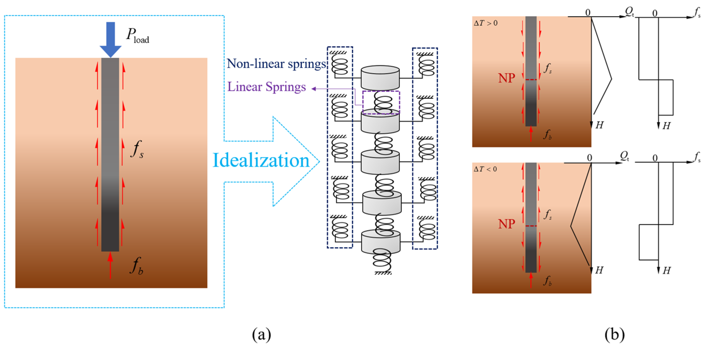
The load transfer method requires the pile body to be divided into several elastic units, and the contact between the pile side, the pile end, and the surrounding soil is replaced by nonlinear springs. Specifically, the relative displacement s of the pile-side and pile-tip resistances with respect to the surrounding soil can be represented by a load–transfer model. (He Huibin et al. [
18], 2008; Li Yonghui et al. [
19], 2011; Chen Min et al. [
20], 2016; SONG et al. [
21], 2023), as shown in
Figure 1a. To simplify the calculations, the following assumptions were made: First of all, the positive direction of displacement and force is made as follows: displacement downward is positive, strain and stress direction are the same, both are positive by pressure, and the positive direction of frictional force is upward. Secondly, it is assumed that the modulus of elasticity
E, thermal expansion coefficient α, and pile-soil interaction relationship are not affected by temperature. Lastly, considering that the radial dimension of the pile is much smaller than the axial dimension, the effect of temperature on the axial deformation of the pile is ignored.
When using the load transfer method of energy piles, it is necessary to determine the location of the neutral surface of the energy pile at first, so the definition of the neutral surface and the method of determining the location of the neutral surface are described next.
2.1. Neutral Surface Definition and Determination Method
According to the assumption that the energy pile can be regarded as a one-dimensional linear heat source. The change of pile temperature will lead to tensile or compressive deformation in the axial direction. Therefore, there must be a cross-section along the pile direction that does not generate strain; the cross-section is called the neutral surface, noted as NP. When the pile is not restrained, the temperature change will cause the pile to deform freely, and the neutral surface is located at the midpoint of the pile without additional temperature stress. In practical engineering applications, however, energy piles are embedded in soil masses and are constrained by both the surrounding soil and the pile-end bearing stratum, resulting in variations in the neutral plane position. As shown in
Figure 1b, when only the effect of temperature is considered, the energy pile is compressed and has the maximum axial force at the neutral surface when the temperature rises, and the upper part of the pile generates negative frictional resistance; when the temperature decreases, the energy pile is pulled and has the maximum axial force at the neutral surface, and the lower part of the pile generates negative frictional resistance.
Where is the mechanical load acting on the top of the pile; and represent the lateral resistance and end resistance of the pile respectively; is the axial force of the pile; is the variable of the temperature; and H is the depth of pile.
Firstly, the location of the neutral plane needs to be determined when exploring the thermomechanical coupling properties of energy piles using the load transfer method. It is worth noting that the mechanical equilibrium conditions for the neutral plane should satisfy the following equation.
where
is the lateral frictional resistance of unit
i of the pile;
is the end resistance; and
represents the vertical structural load (Knellwolf et al. [
15], 2011).
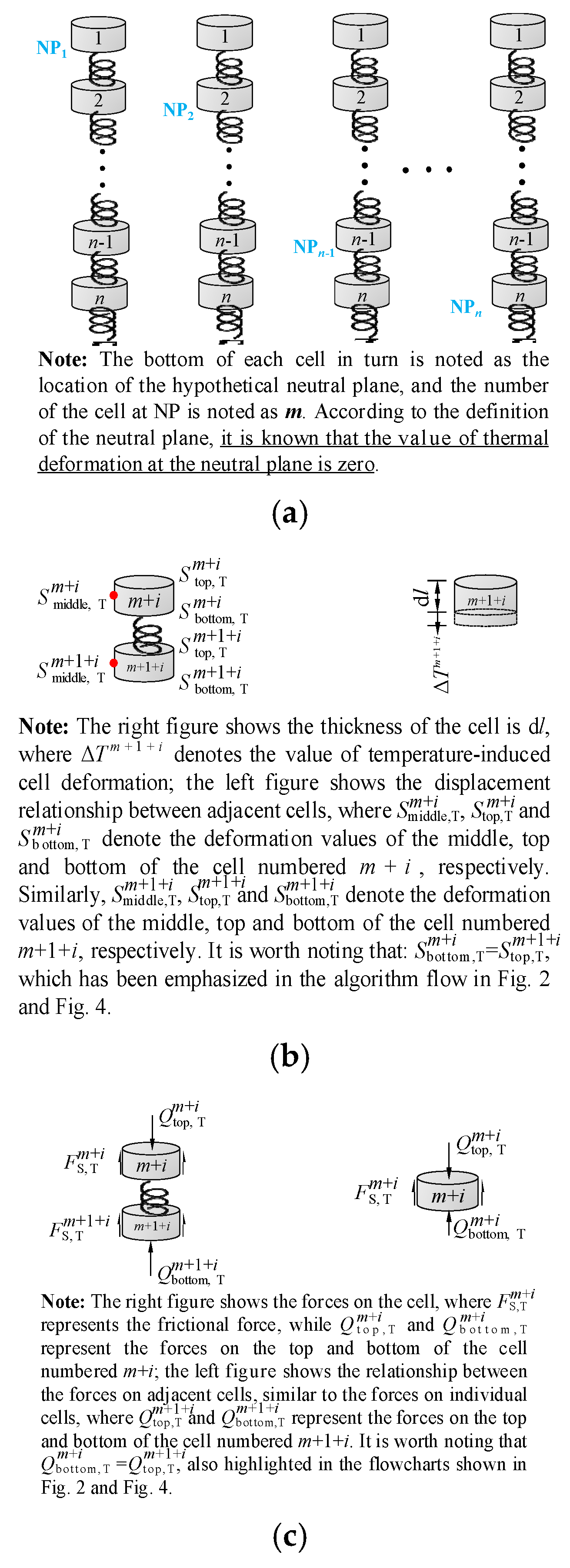
When the pile is discretized into a number of elasticities, the neutral surface can only exist on the face where the unit nodes are located. Therefore, the nodes of the pile are assumed to be the neutral surface in turn from top to bottom, and the combined force at the neutral surface is calculated according to Equation (1). The hypothetical neutral surface that makes the combined force minimum is approximated as the actual neutral surface, i.e., the mechanical equilibrium condition at the neutral surface when using the load transfer method for energy piles should satisfy Equation (2) (Knellwolf et al. [
15], 2011).
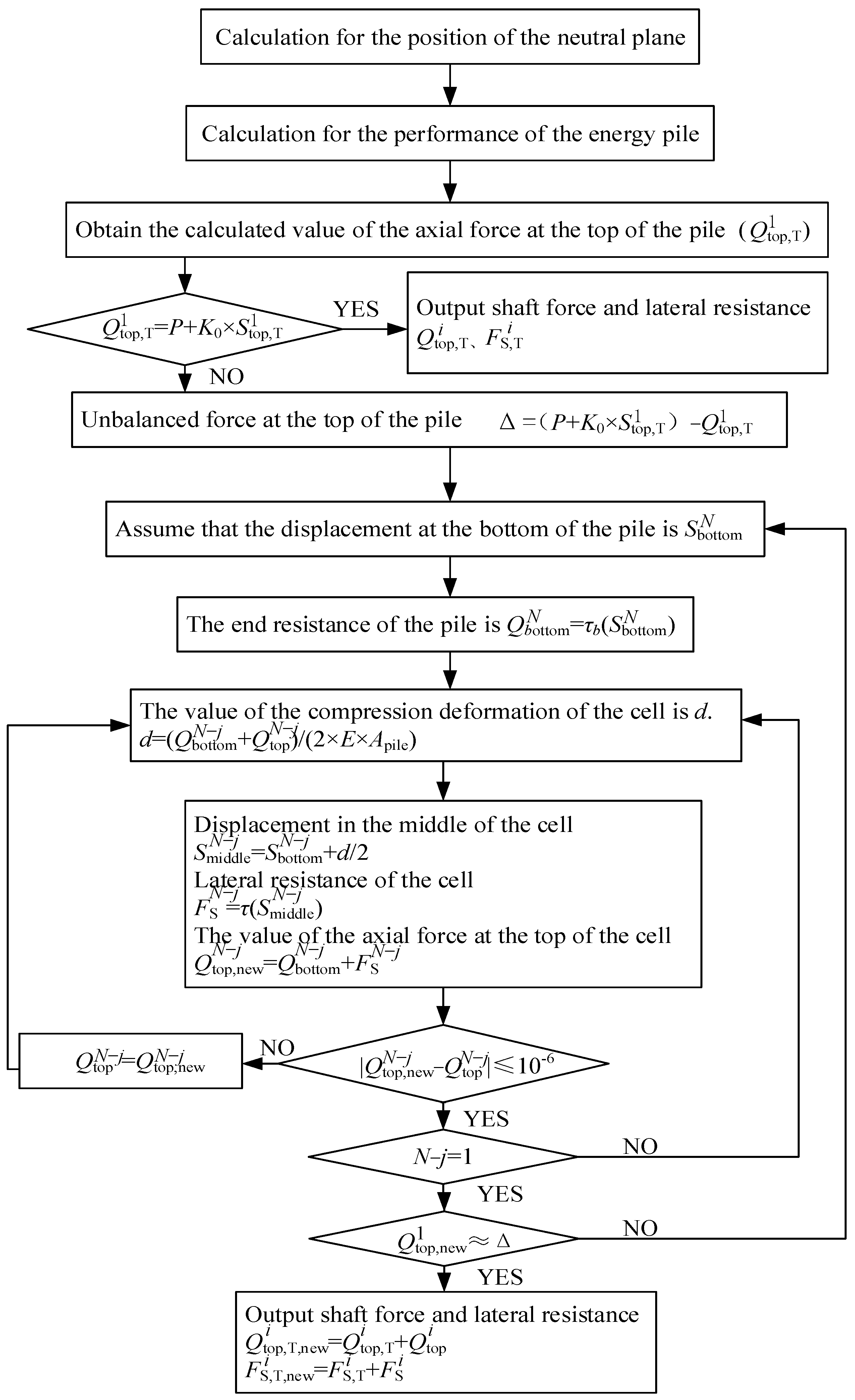
Then, the deformation due to temperature change at the location of the neutral surface is zero as a known condition, and the axial force and strain values of the pile due to temperature are calculated from the node location of the neutral surface to both sides, respectively. Therefore, when using the load transfer method to explore the thermal-mechanical coupling bearing characteristics of the energy pile, it is first necessary to determine the displacement where the neutral surface of the energy pile is located. The definition and determination method of the neutral surface have been explained in detail above, and the flow chart of the algorithm for determining the neutral surface is shown below. The meaning of the equations designed into the flow chart (
Figure 2) is shown in
Figure 3, which shows the process of determining the neutral surface more graphically through the form of a schematic diagram.
2.2. Load Transfer Methods for Energy Piles
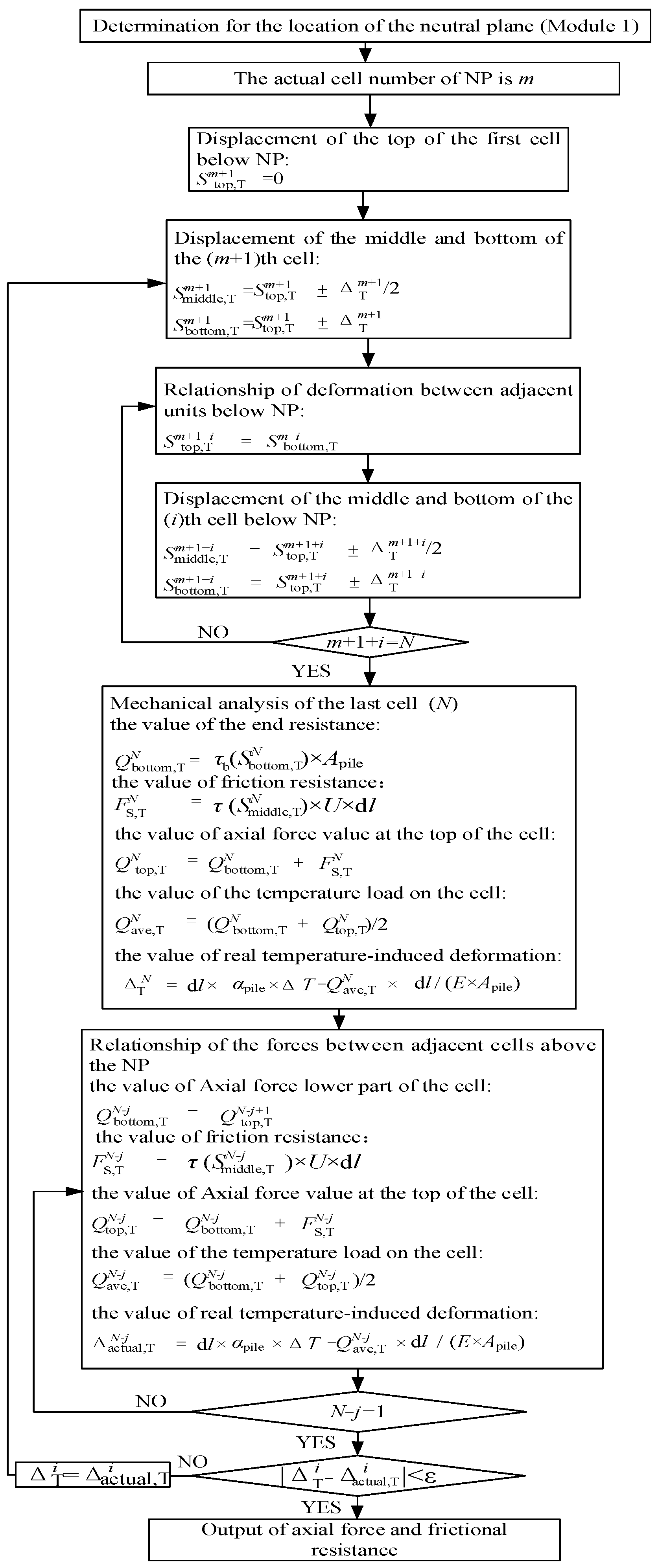
The location where the longitudinal deformation of the energy pile is zero after the temperature influence on the pile, i.e., the location of the neutral surface, can be found by following the method shown in
Figure 2. This is also a prerequisite for using the load transfer method. Once the location of the neutral surface is found, the second module of the load transfer method, i.e., the module for calculating the performance of the energy pile, can be applied, and the corresponding calculation process is shown in
Figure 4.
2.3. Improvement of Load Transfer Method for Energy Piles
2.3.1. Find the Problem
Figure 2,
Figure 3 and
Figure 4 show the algorithm of the coupled thermo-mechanical analysis method for the energy piles established by Knellwolf [
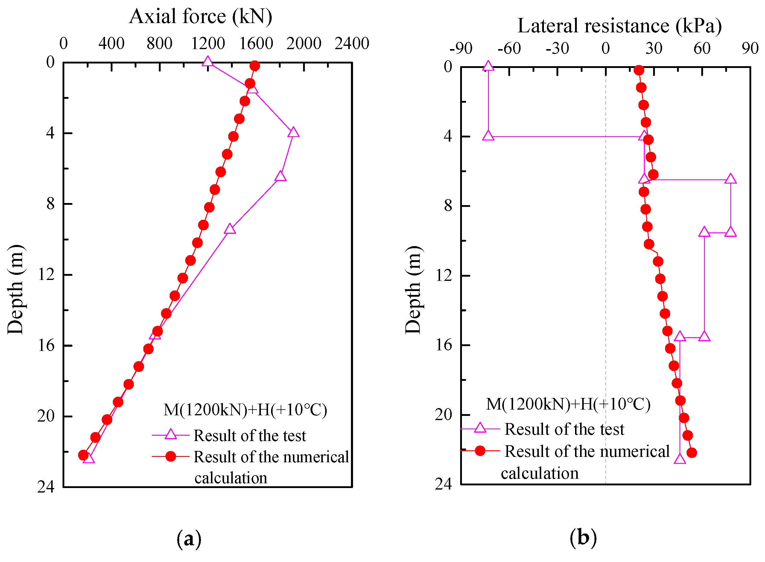
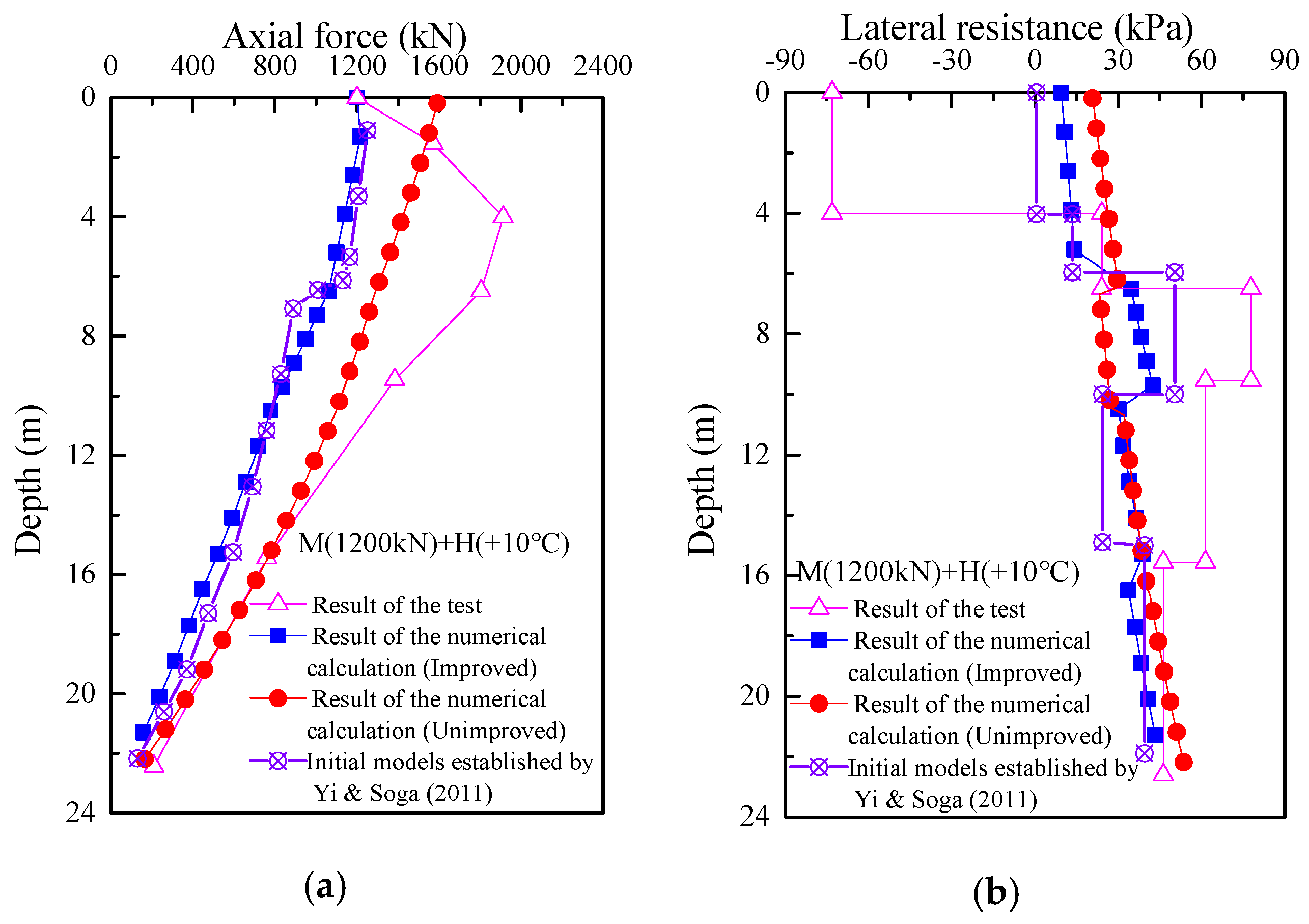
15] (2011), and now the London energy pile in-situ test is investigated using the adapted method. The pile used in this test has a diameter that is 0.6 m, a length that is 22.5 m, a modulus that is 40 GPa, and a coefficient of thermal expansion that is 8.5 × 10
−6 °C
−1. The parameters of the physical and mechanical indexes of the soil layer in this test are shown in
Table 1. While the static load test is in effect, the energy pile heat transfer test is conducted through the heat transfer tube, and the force on the top of the energy pile is controlled to be constant, i.e., the load is maintained at 1200 kN during the test so as to obtain the load transfer characteristics of the energy pile under the coupled thermo-mechanical action, and the field test and calculation results are shown below. A comparison of the calculated results with the field test results is shown in
Figure 5. It can be found that the calculated top loading of the pile is 1591.46 kN, while the actual loading is 1200 kN, a difference of 391.46 kN, i.e., the error between the calculated and actual loading is 32%, so it can be considered that the load transfer characteristics of the energy pile under the coupled thermo-mechanical action cannot be accurately calculated by the above method.
2.3.2. Analyze the Cause
The analysis shows that both the size of the cells and the equilibrium condition of the neutral surface may lead to the phenomenon that the calculated axial force does not match the actual loading condition at the top of the pile. This is due to the mismatch between the unit size and the calculation tolerance error. Therefore, the matching degree of the cell’s size and the calculation tolerance of the error will lead to the non-convergence of the calculation results, so the matching problem between the size of the cell and the calculation tolerance of the error in the load transfer method is also the difficulty of the method. Therefore, the problem of matching the cell size and the computational tolerance of the error in the load transfer method is also a difficult point in the promotion of the method, which will not be discussed too much in this paper. In the following, the reasons for the mismatch between the axial force calculated from the neutral plane equilibrium condition and the actual load at the top of the pile will be discussed, the iterative method to eliminate the unbalanced force at the top of the pile will be used, and an iterative algorithm to eliminate the unbalanced force at the top of the pile will be proposed so that the load transfer displacement coordination method can accurately reflect the load transfer characteristics of energy piles coupled under thermodynamic action.
2.3.3. Improve the Method
It has been mentioned above that the calculated results of the load transfer method established by Knellwolf [
15] (2011) applied to the study of energy piles showed large deviations between the calculated axial force values at the top of the pile and the actual loading. After analysis, it is known that this is caused by using
instead of
in determining the neutral surface. Although this method can determine the approximate location of the neutral plane, it also brings a large error to the calculation results of the pile top, which can be recorded as the pile top unbalance force. The iterative algorithm for pile top unbalance force elimination established in this paper can well solve the pile top error brought by the above problem, and the specific steps are as follows.
Step 1: The approximate location of the neutral surface is determined according to the algorithm shown in
Figure 2.
Step 2: The distribution of the axial force, strain, and lateral resistance of the energy pile along the pile is determined according to the algorithm shown in
Figure 4.
Step 3: The value of the loading at the top of the pile is known and is denoted as P. The calculated axial force at the top of the pile is denoted as . The difference between them is calculated as the unbalanced force at the top of the pile.
Step 4: The unbalanced force at the top of the pile obtained from the calculation is added back to the top of the pile, and the axial force, strain, and displacement due to the unbalanced force are obtained using the load transfer method.
Step 5: The axial forces, strains, and displacements due to unbalanced forces are superimposed on the results calculated by the algorithms shown in
Figure 2 and
Figure 4, thus updating the results of the axial force, strain, and displacement distribution of the pile.
The flow chart of the iterative algorithm for the unbalanced force at the top of the pile is shown below.
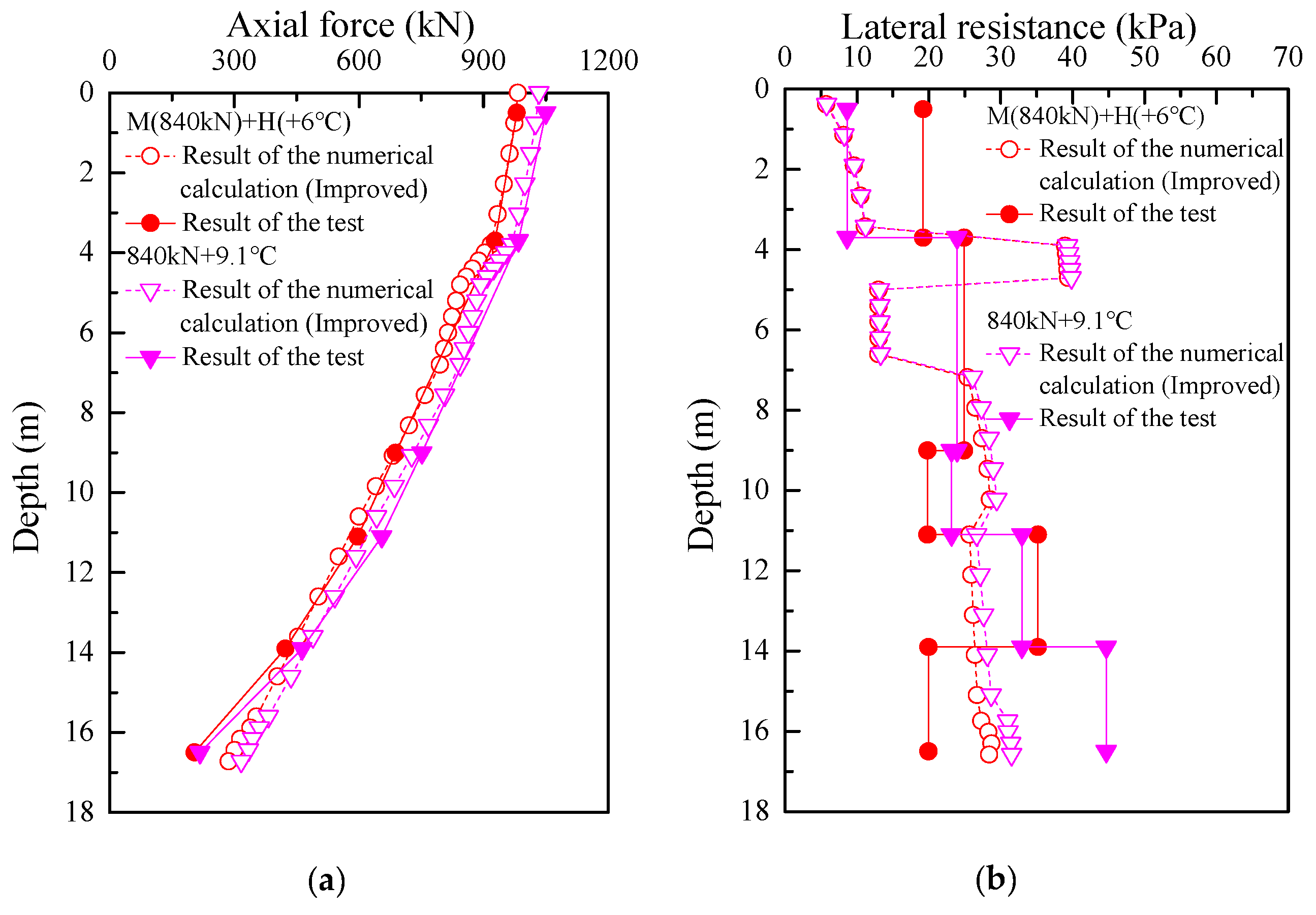
The test conditions shown in
Figure 6 were calculated and analyzed according to the iterative algorithm for the elimination of the unbalanced forces at the top of the pile. The calculated results were also compared with the results of the load transfer method established by Knellwolf, the test results, and the matrix displacement method constructed by Ouyang et al. [
22], as shown in
Figure 7. It can be found that the axial force at the top of the pile calculated by the improved method is consistent with the value of the actual loading at the top of the pile, and the results of the axial force and lateral resistance distribution along the pile body obtained by the method are consistent with the pattern of the experimental values, and the results are similar, which can better reflect the effect of thermo- mechanical coupling on the performance of energy piles.


