Article

Fracture Evolution Mechanisms and Roof Failure Assessment in Shallow-Buried Soft Coal Seams Under Fully Mechanized Caving Mining

Key Laboratory of In-Situ Modified Mining, Ministry of Education, Taiyuan University of Technology, Taiyuan 030024, China
*
Author to whom correspondence should be addressed.
Appl. Sci. 2025, 15(11), 6036; https://doi.org/10.3390/app15116036
Submission received: 26 February 2025 / Revised: 21 May 2025 / Accepted: 26 May 2025 / Published: 27 May 2025
(This article belongs to the Special Issue Technologies and Methods for Exploitation of Geological Resources)

Abstract

To address the challenges in the collaborative control of strong mine pressure and surface damage during fully mechanized shallow soft coal seam top-coal caving mining, this study takes the 22,031 working face of Xindeng (Zhengzhou, China) Coal Mine as the research background. By combining analytical modeling and discrete-element granular flow simulation, this research elucidates how overburden fractures evolve and how the ground surface responds throughout the mining of shallow, soft coal seams. This research shows that the mechanical model analysis based on plate theory indicates that the first fracture of the immediate roof occurs 0.5 m from the goaf side of the mined-out area. Numerical simulations demonstrate that when the working face advances 80 m, the mining-induced influence extends to the surface. The displacement field of the overburden undergoes a dynamic temporal evolution law following the sequence of “rectangle–trapezoid” → “hyperbola-like” → “trapezoid”. During the advancement of the working face, the fracture pattern of the overburden evolves from “rectangle–trapezoid” to “trapezoid”, and the affected range on the surface transforms from an “inverted trapezoid” to a “trapezoid”. This study ultimately clarifies the dynamic law of collaborative deformation between the overburden and the surface, providing a theoretical basis for the safe mining of shallow coal seams, the prevention of roof accidents, and the optimization of mining technology.

1. Introduction

At present, there are still a large number of coal seams with shallow burial depths in China. However, due to the fact that coal seams with shallow burial depths usually have a single structural feature, the overlying rock movement and mine pressure characteristics are also relatively obvious. During coal seam mining, upon goaf formation, the roof is subjected to stripping forces and gradually subsides [1,2]. The subsidence of the roof leads to the redistribution of the pressure in the goaf, and the ground pressure is transmitted to the boundary rock mass, causing the deformation and stress relaxation of the boundary rock mass, which will have a certain impact on the stability of the surrounding rock. The study of the movement law of the overlying rock of the working face after coal seam mining is of great significance for coal mine safety and mining efficiency [3].
To achieve safe mining in weak coal seams with fully mechanized caving faces, it is crucial to have a correct understanding of the evolutionary law of overlying rock movement and fracture in the stope. In recent years, numerous researchers have conducted extensive studies on the laws of overlying rock movement under various stope and geological conditions. Wang et al. [4] confirmed the significant role of the “masonry beam” structure in mining pressure control and mining-induced stress distribution through in-depth research on the “masonry beam” mechanical model of stope ground pressure. Kwasniewski M. et al. [5,6] constructed large-scale two-dimensional models through integrated theoretical analysis and UDEC numerical simulations, revealing the dynamic evolution mechanisms of mining-induced fracture networks and determining the optimal advancement rate and support specifications. Sun et al. [7] investigated the full-cycle multi-physical response characteristics of rock strata deformation and fracturing collapse under extra-thick coal seam conditions through similarity simulation tests combined with an independently developed optoelectronic multi-parameter distributed sensing system. Sun et al. [8] analyzed the full-cycle overlying rock movement laws in high-stage fully mechanized caving faces of steeply dipping extra-thick coal seam groups by collecting surface displacement data and mapping displacement programs using MATLAB, revealing the relationship between stope pressure and overlying rock movement. Chang et al. [9] studied the roof weighting and overlying rock movement characteristics in shallow-buried thick coal seams with fully mechanized caving faces. Results showed that key stratum fracture causes violent overlying rock movement, with goaf overlying strata collapsing upward in regular arcs and failure often exhibiting a “saddle” morphology. Li et al. [10] established a “masonry beam” mechanical model for mining slopes and revealed the dynamic evolution law of the “masonry beam” structure and the impact of key rock block B rotation on slope instability through physical/numerical simulation and mechanical analysis of overlying rock movement in side-slope coal mine stopes. Li et al. [11] compared overlying rock movement/fracture and surface damage characteristics between pillarless mining and coal pillar mining in shallow-buried ultra-thin coal seams using 3DEC numerical simulation and field tests. Based on the key stratum theory, they derived a critical formula for hard rock collapse height. Wang et al. [12] studied the overlying rock movement laws in steeply dipping coal seam stops under dip-gravity field effects through combined physical similarity simulation, numerical simulation, and theoretical analysis. Nan et al. [13] identified the roof weighting sources and determined support load calculation methods for fully mechanized caving faces under upper coal seam disturbance using theoretical analysis and similarity simulation, revealing the overlying rock movement laws in disturbed conditions. For shallow coal mines, researchers have also conducted studies on dynamic pressure loading, overburden migration patterns, and surface crack development [14,15,16,17].
On this basis, there is limited research on the overlying rock fracture laws in weak coal seams in fully mechanized caving faces under atypical shallow burial depth characteristics. Taking Henan Xindeng (Zhengzhou, China) Coal Mine as the engineering background, this study combines theoretical analysis with discrete element particle flow numerical simulation to investigate roof fracture location and patterns, the time evolution law of vertical displacement, surface subsidence characteristics, and evolutionary stages of overlying rock fractures. The research results provide significant guidance for safe production in working faces by revealing the dynamic mechanical behavior of overlying strata under complex geological conditions.

2. Materials and Methods

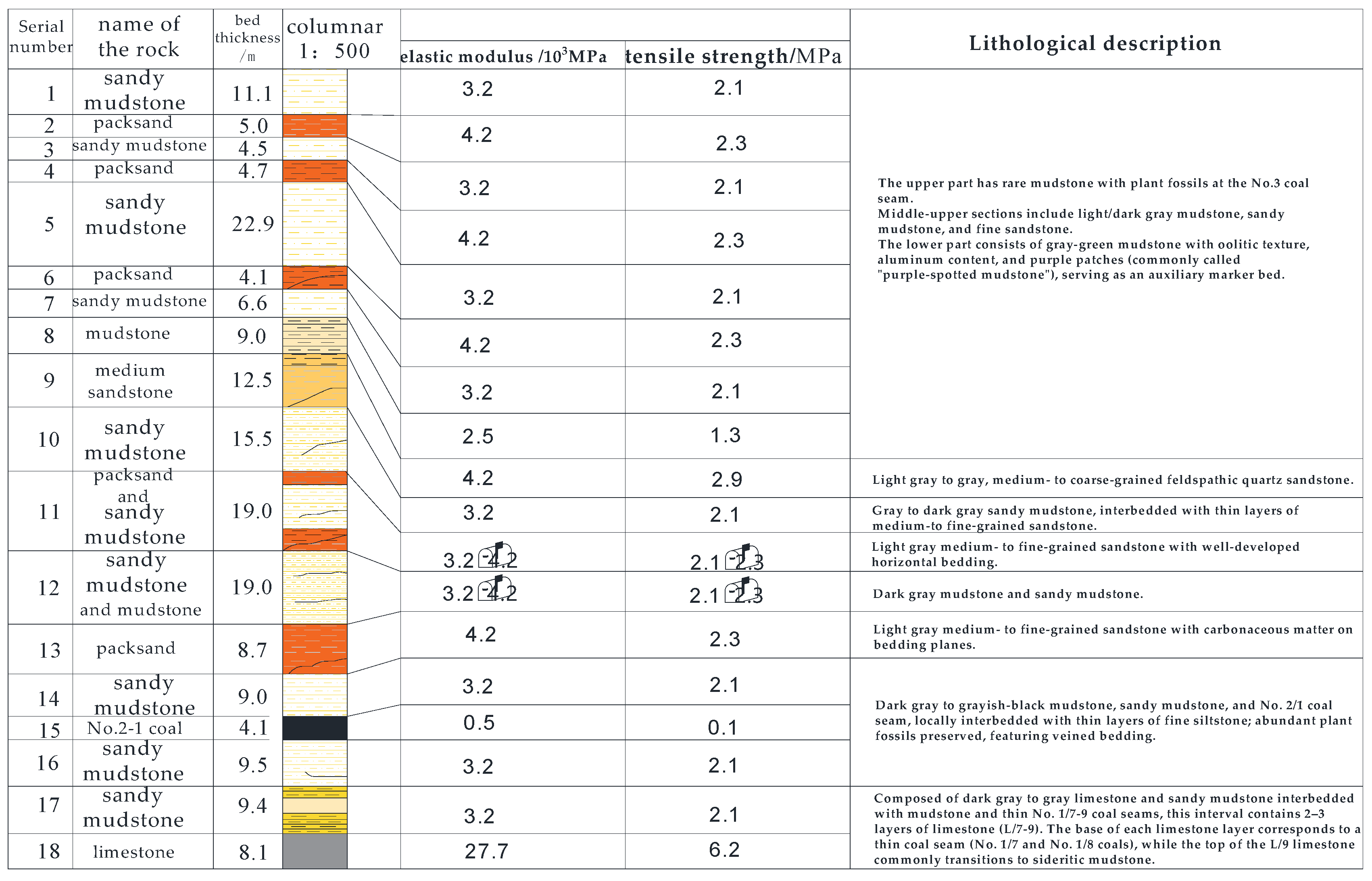
2.1. General Situation of the Project

The 22,031 working face of Xindeng (Zhengzhou, China) Coal Mine mainly mines the 2-1 coal seam, with a vertical distance from the surface ranging between 120 and 150 m. These data are provided by Xindeng (Zhengzhou, China) Coal Industry based on on-site measured data obtained through geological surveys of the actual geological conditions in the working face. The comprehensive coal-rock column diagram is shown in Figure 1. The coal seam exhibits an average dip angle of 8°, thereby classifying it as a gently inclined seam. The burial depth is 120–150 m, the working face length is 119 m, the mining length is 560 m, and the mining area reaches 66,640 square meters. No gangue interlayers are found in the coal seam, so the structure of the 2-1 coal seam in the working face is relatively simple. Experimental data show that the rock mass integrity coefficient for this seam corresponds to Class III–IV fractured coal. Broadly speaking, the coal seam at the 22,031 face is weak, and its roof and floor layers are soft, with a thick immediate roof that will collapse during the extraction process.
In order to maintain safe production on site and enable the smooth execution of gob-side entry retaining techniques in this working face, it becomes necessary to study the dynamic laws of overlying rock strata and the failure modes of the roof structure. As the working face advances, the exposed length of the roof gradually increases. If a fracture occurs in the unsupported area, it is highly likely to trigger a roof fall accident. According to the analysis results of the mechanical model based on thin plate theory, the initial fracture of the immediate roof occurs 0.5 m away from the lateral side of the goaf. Studying the relationship between the fracture position and the advancing step distance can optimize the support timing and effectively prevent roof collapse. Hence, via the combination of field monitoring and numerical simulation to trace real-time roof fracture dynamics and compare theoretical analysis outcomes with practical data, the roof support strategy can be enhanced, furnishing a reliable reference for the safe and high-efficiency application of gob-side entry retaining technology.

2.2. Mechanical Model and Fracture Analysis of the Roof After Coal Seam Mining

2.2.1. Basic Assumptions

During the mining of the No. 2-1 coal seam, the immediate roof experiences sudden caving, which leads to the main roof above the goaf being sustained in an equilibrium state of suspension. The suspended main roof is constrained between the overlying and underlying rock layers, with the stiffness of these adjacent strata being lower than that of the main roof itself. Under this mechanical configuration, an elastic foundation boundary model can be developed on the premise that the main roof is bounded by elastic strata both above and below, accompanied by the following fundamental assumptions:
(1)
Given that the length of the main roof’s suspended section along the working face direction surpasses 13 times its thickness, it is reasonable to model this structural element as a 1 m wide beam element aligned with the working face direction.
(2)
The strata above and below the main roof are regarded as elastic foundation layers conforming to the Winkler elastic foundation theory, while the main roof is modeled as a beam element supported by this dual elastic foundation framework.
(3)
It is assumed in the model that deformation compatibility exists without shear displacement at the interface between the main roof and the elastic foundation. This assumption specifically addresses scenarios with significant stiffness contrasts between the primary roof and the overlying/underlying weak strata (immediate roof/coal seam) in the study area. In practical conditions where weak interlayers exist, shear slippage may induce stress concentration at the roof edges, potentially exacerbating fracture risks.
(4)
The overburden load is simplified as a uniformly distributed stress field, omitting the mining-induced stress arching effect. This simplification is valid for shallow-buried coal seams (burial depth: 120–150 m, where stress arching remains underdeveloped) but requires modification for deep mining applications. Given this study’s focus on shallow-buried, weakly cemented strata, the uniform loading assumption satisfies engineering accuracy requirements. The stress arching effect will be explicitly addressed in subsequent comparative studies of deep versus shallow coal seam mechanics.

2.2.2. Establishment and Solution of the Mechanical Model

Based on the mining geological conditions of the 22,031 working face in XinDeng (Zhengzhou, China) Coal Mine, to simplify the calculation process, the load acting on the main roof is idealized as a uniformly distributed load, and the effect of plastic deformation failure in the underlying strata on elastic foundation parameters is not considered. Selecting the section at a certain distance behind the working face as the research object, a mechanical model is developed to characterize the interaction between the roof and underlying coal-rock strata following coal seam extraction, as shown in Figure 2. In this notation, q represents the load exerted by the overlying strata on the main roof; k signifies the Winkler elastic foundation coefficient; h denotes the main roof thickness; L indicates the exposed length of the main roof along the working face direction; and D stands for the flexural rigidity of the main roof.
(1)
Differential Equation of Main Roof Deflection
For the main roof above the goaf, the differential equation of roof deflection is
D j d 4 ω 1 d x 4 = q
In the equation, ω(x) denotes the deflection of the main roof, while q(x) represents the load imposed by the overlying strata.
For the main roof sections flanking the gob area, the differential equation governing roof deflection is
D j d 4 ω 2 d x 4 + K d 2 w 2 d x 2 = q
In the equation, ω 2 x is the vertical deflection within the support area; the extra term K d 2 ω 2 / d x 2 represents the restoring force of the Winkler spring.
(2)
Model Boundary Conditions
In the far-field region away from the gob area, the main roof is subject to a fixed constraint between the overlying and underlying strata, where both the deflection and rotation angle of the main roof remain zero. At the boundary of the gob area, the main roof exhibits continuity in deflection, rotation angle, bending moment, and shear force.
(3)
Model Solution Process
The model depicted in Figure 2 is axisymmetric with respect to the o-z axis, so only the left half of the main roof’s deflection equation requires a solution. The general solution forms of Equations (1) and (2) are derived as follows:
ω 1 ( x ) = q 24 D j + C 1 x 3 + C 2 x 2 + C 3 x + C 4
ω 2 ( x ) = e α x C 5 sin ( α x ) + C 6 cos ( α x ) + e α x C 7 sin ( α x ) + C 8 cos ( α x )
In the equation, C 1 ~ C 8 are unknown coefficients; α = K D j 4 .
Based on the model’s boundary conditions, the following equations can be derived:
lim x ω 1 x = 0 , lim x ω 1 x = 0
ω 1 0 = ω 2 0 ω 1 0 = ω 2 0 ω 1 0 = ω 2 0 ω 1 0 = ω 2 0
Given that the rotation angle and shear force at the central axis of the model vary, the following equations can be derived:
ω 2 ( L ) = 0 ω 1 ( L ) = 0
By substituting the above conditions into the general solutions (1)–(2), the constants C 1 to C 1 can be determined in sequence:
C 2 = q k 2 L 2 + 2 k L + 4 D j 24 D j k L + 2 D j
C 4 = q k 2 L 3 k L + 2 D j 384 D j k L + 2 D j
C 5 ,   C 6 ,   C 7 ,   C 8
In the equation, D = E j h j 3 12 1 v j 2 .

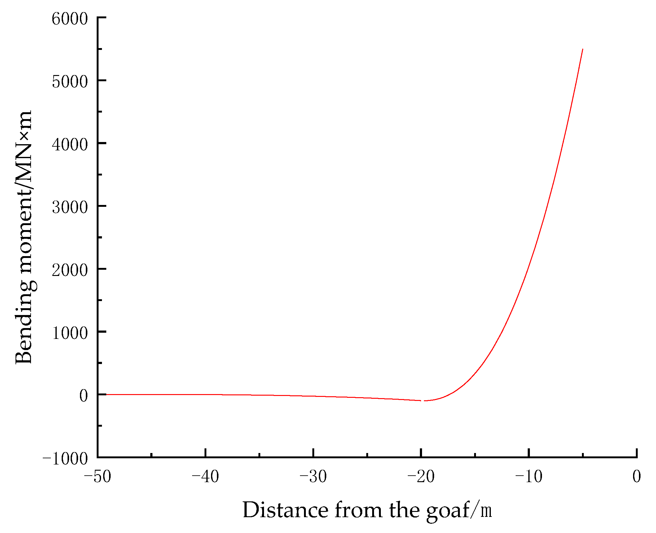
2.2.3. Analysis of the Roof Fracture Location

In engineering and physics, the bending moment of a beam refers to the bending moment caused by external forces at a certain section of the beam. The bending moment exhibits an intimate connection with the beam’s cracking site, a relationship that can be interpreted via stress analysis of the beam. Typically, the main roof failure occurs at the position of maximum bending moment, more precisely on its upper and lower surfaces. This is because at this position, the transverse stress of the main roof reaches the maximum value, exceeding the tensile strength of the rock material, resulting in failure. Therefore, the correlation between the bending moment and the main roof’s fracture location can be synthesized as follows: the position with the peak bending moment typically serves as the primary fracture site of the main roof. Through analyzing the bending moment distribution of the main roof, the failure position of the main roof can be predicted, and a reasonable support design can be carried out [18].
The calculation formula of the bending moment of the main roof is as follows:
M = E j h j 3 12 ω 2 x
When the geological data and mining parameters of XinDeng (Zhengzhou, China) Coal Mine’s 22,031 working face are plugged into Equation (10), the derived bending moment curve of the main roof is depicted in Figure 3. It can be seen from the figure that after the No. 2-1 coal seam is mined, under the action of the overlying strata load and the support of the underlying coal and rock strata, bending tensile stress appears in the main roof. The position with the largest bending moment is near the goaf, about 0.5 m away from the edge of the goaf, indicating that if the main roof fractures, the fracture position is about 0.5 m away from the edge of the goaf.

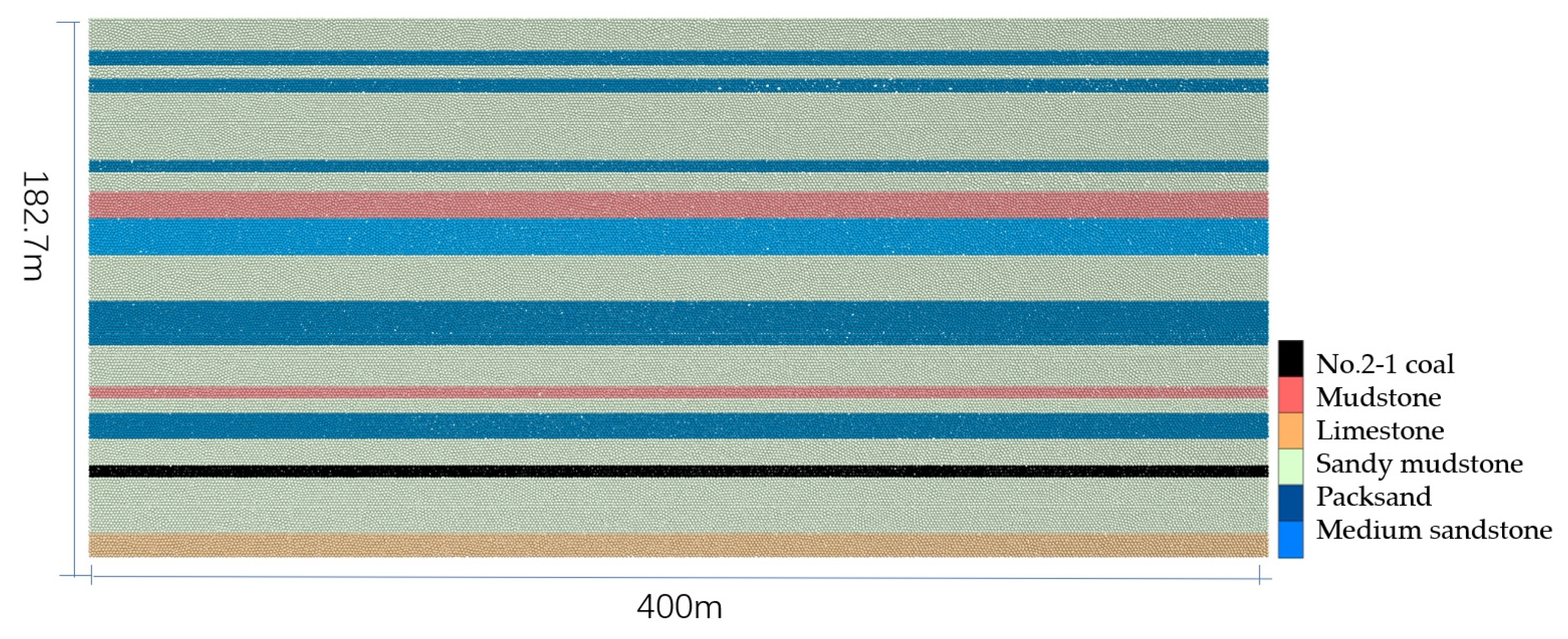
2.3. Establishment of the Numerical Model

The Particle Flow Code (PFC 2D) v7.0, developed by Itasca, is a discrete element analysis software that is widely used in the field of geotechnical engineering to simulate the mechanical behavior and interactions of granular media. Based on the actual geological conditions of the 22,031 working face of XinDeng (Zhengzhou, China) Coal Mine, a particle flow numerical calculation model of overburden rock migration during working face mining is established as shown in Figure 4. The size is 400 m × 1 m × 182.7 m (length × width × height). The left and right boundaries constrain the horizontal lateral displacement, the bottom is fixed, and a uniform load of 2.7 MPa is applied on the top. When simulating the working face mining, the No. 2-1 coal is mined with a 10 m advancing step each time. The physical and mechanical parameters of each rock layer are taken from Table 1. The model is generated by the extrusion exclusion method. After the model is assembled, the initial ground stress is applied. Among them, the load layer is directly converted into a force load and applied to the top particles of the model. After the model reaches equilibrium under the initial ground stress, the working face advancement simulation is carried out. The model is shown in Figure 4.

3. Results and Discussion

3.1. The Fracture Law of the Overlying Rock

The caving of the immediate roof is shown in Figure 5, which illustrates the strata-caving conditions when the working face is advanced by 40 m and 50 m. Due to its low strength and the softness of the rock strata, during the early stage of the working face advancement, the phenomenon of caving as the coal is mined occurs. The immediate roof, with a relatively large thickness, can effectively fill the goaf after caving, which is conducive to the formation of a stable structure in the overlying rock strata.
When the working face advanced to the critical position of 70 m, the primary roof experienced its initial fracture instability. As shown in Figure 5, illustrating overburden movement, distinct stratification occurred in the upper strata, with the main roof reaching its critical span and initiating collapse. The fracture location demonstrated minimal relative error compared with theoretical calculations, validating the computational rationality. The analysis of fracture position proves crucial for understanding intense strata pressure manifestations post-fracture. The observed fracture occurring on the goaf side effectively reduced the probability of severe ground pressure disasters, providing significant guidance for safe mining practices [19]. Moreover, the substantial thickness of the immediate roof provided partial backfilling in the mined-out area, restricting sufficient rotational space. Temporary V-shaped articulated structures formed after preliminary contact between collapsed roof strata and gangue. The overlying strata subsequently collapsed with asynchronous settlement, creating bed separation fractures. The measured initial weighting interval of 70 m showed 7.9% deviation from field observations, demonstrating reasonable agreement with actual mining conditions.
As advancement continued to 80 m, the fractured main roof fully compacted with goaf gangue, forming a stable V-shaped articulated structure exhibiting remarkable mechanical stability during strata movement.
At 90 m advancement, the first periodic weighting occurred, accompanied by distinct bed separation between collapsed strata and key stratum, while only minor fractures developed in the key stratum without evident collapse. The overburden collapse configuration transitioned to trapezoidal morphology, with central strata gradually compacting and expanding along both advancing and vertical directions. The third periodic weighting at 120 m advancement witnessed vertical fracture propagation reaching maximum height, with Figure 5 illustrating final collapse morphology at 250 m advancement.
Upon reaching the 100 m critical position, the principal key stratum underwent initial fracture instability with subtle yet measurable subsidence, as shown in Figure 6. Subsequent advancement triggered complete rupture of the principal key stratum, fundamentally altering load transfer mechanisms within the overburden and inducing progressive instability that ultimately manifested as surface subsidence. The collapse patterns of overlying strata were predominantly governed by fracture characteristics of both the main roof and key strata.
When the working face is advanced to 90 m, the first periodic weighting occurs at the working face. After the rock strata cave in and break, obvious separation cracks form between them and the key stratum. At this moment, there are a few slight cracks in the key stratum, but there are no obvious signs of caving. The overall caving of the overlying rock strata presents a “trapezoid” shape. The rock strata in the middle gradually evolve towards compaction, and with the advancement of the working face, they gradually expand in the advancing and vertical directions. When the working face is advanced to 120 m, the third periodic weighting of the main roof occurs, and the cracks vertically extend to the maximum height. As shown in the figure, the final caving shape of the overlying rock strata is presented when the working face is advanced to 250 m.

3.2. The Time Evolution Law of Vertical Displacement of Overlying Rock Strata

During the coal-mining process, the overlying rock strata will be broken, subside, and become unstable. This will inevitably lead to the horizontal dislocation and the change in vertical displacement in the overlying rock strata [20]. To further analyze the movement state of the overlying rock strata during the mining of the working face of the shallow-buried soft coal seam, this paper mainly studies and analyzes the vertical displacement. Since the horizontal displacement is relatively small, it will not be analyzed here.
When the working face is advanced to 60 m, as shown in Figure 7, in addition to the immediate roof, a small amount of displacement also begins to appear in the main roof. When the working face is advanced to 70 m, as shown in the figure, with the continuous advancement, the main roof reaches its ultimate span, and obvious displacement changes occur in the main roof above the entire goaf. The overall displacement trend gradually decreases from the middle of the working face to both sides. The maximum subsidence value in the middle of the working face is 2.99 m. This indicates that the middle area of the overlying rock strata is greatly affected by the mining, but it has no impact on the rock strata above the key stratum. At this moment, the overall displacement field exhibits a “rectangle–trapezoid” configuration. The displacement of the overlying rock strata of the working face is symmetrically distributed along the middle.
When the working face is advanced to 80 m, as shown in Figure 7, the displacement gradually expands upward. The displacement in the middle area of the overlying rock strata has expanded to the ground, and the overall subsidence of the upper rock strata is 0.67 m. The change is not obvious, but a certain trend has been shown. With the fracture of the key stratum, the overlying rock strata it bears will show obvious caving and subsidence phenomena. When the working face is advanced to 100 m, the key stratum has begun to cave and subside, the range of the displacement area in the middle of the overlying rock strata is expanding, and obvious settlement appears on the ground surface. Until the working face is advanced to 250 m and the mining is completed, the movement area of the overlying rock strata continues to expand along the advancing direction. Finally, in the vertical direction, there is a negative correlation between the height of the overlying rock strata and the subsidence amount; in the horizontal direction, the displacement gradually decreases from the area near the middle to both sides. Due to the different mechanical properties and the degrees of influence by mining of the overlying rock strata at different layers, the magnitude and distribution of their displacements will also be different. Therefore, the displacement of the upper overlying rock strata is relatively small, and the displacement of the lower overlying rock strata is relatively large, showing that the movement of the overlying rock strata has a certain stratification. The shape of the overall displacement field evolves from the “rectangle–trapezoid” (the formed rectangle has a length of 60.6 m and a width of 17 m; the trapezoid features a top base of 63.1 m, a bottom base of 80 m, and a height of 30.5 m) shape in the early stage to the “hyperbola-like” shape in the middle stage and finally evolves into a “trapezoid” shape (the formed trapezoid features a top base of 214.9 m, a bottom base of 250 m, and a height of 154 m).
As the working face advances, the displacement of the overlying rock strata gradually increases. The middle area of the overlying rock strata is always the area most affected by mining, and the area with larger displacement will gradually expand, showing a certain time evolution trend. In addition, it can also be seen that from the initial stage of mining, the overlying rock strata may first generate small displacements in local areas. With the progress of mining, the displacements gradually expand around, forming a certain displacement propagation path and range, and finally reaching a relatively stable state. The movement of the overlying rock strata shows a dynamically stable process.

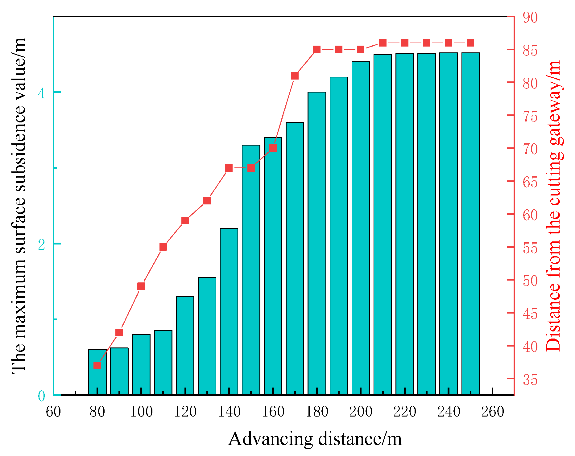
3.3. Analysis of Ground Surface Subsidence

Due to its special geological conditions, with a shallow burial depth and weak rock strength, when the working face is advanced to 80 m, the overlying rock strata are affected by mining activities, and the movement of the rock strata spreads to the ground surface. At this moment, the amount of subsidence is small and not obvious. As the working face continues to advance, the overlying rock strata above the goaf lose their original support, and the stress equilibrium state is broken. Figure 8 is a schematic diagram of the ground surface subsidence. Under the action of gravity, the overlying rock strata begin to move and deform towards the goaf. Due to the different mechanical properties and thicknesses of the key stratum and the lower rock strata, during the movement of the rock strata, relative displacements and uncoordinated bending deformations occur between adjacent strata, resulting in the generation of separation cracks between the key stratum and the lower rock strata and the emergence of a caving and subsidence space. After the key stratum breaks, the upper rock strata it bears also cave in and subside accordingly until it affects the ground surface, and an obvious subsidence basin appears on the ground surface, with the maximum subsidence value being 4.57 m.
As can be seen from Figure 9, starting from when the working face is advanced to 80 m until the end of the working face mining, the maximum subsidence value of the ground surface steadily increases in the early and middle stages and gradually stabilizes in the later stage.
Certainly, for the phenomenon of overburden subsidence caused by mining activities, the value of overburden subsidence can also be calculated through formulas, which can, to a certain extent, predict the disasters of ground surface damage and subsidence. This formula integrates the ideas of the stratification method, the probability integral method, and the curve method. It is assumed that under the conditions of multi-seam coalmining or complex geological conditions, for the ground surface subsidence value at a certain coordinate point x , y , it is W t , based on the idea of the stratified summation method, and represents the sum of the ground surface subsidence values caused by each stratum or various factors [21]:
W t = i = 1 n W i
For the ground surface subsidence value W j of each layer i , integrate the probability integral method and the curve method, then W i can be expressed as
W i = W max i × F i x , y
Here, W max i = m i × q i × cos α i , m i represents the mining thickness of the coal seam, q i is the subsidence coefficient, and α is the dip angle of the coal seam. F i x , y is the comprehensive influence coefficient. Then it follows that
F i x , y = ω i e π x 2 r i 2 + y 2 r i 2 + 1 ω i f i x
Therefore, the surface subsidence value is
W t = i = 1 n m i q i cos α i ω i e π x 2 r i 2 + y 2 r i 2 + 1 ω i f i x
Here, ω i is the weight coefficient, and the value range is 0 , 1 . In the region where the geological conditions are relatively uniform, that is, the lithology, mechanical properties, etc., within the mining area change slightly, and the dip angle of the coal seam is small ( α 15 ° ), a relatively large value can be taken for ω i . When the geological conditions in the mining area are relatively stable, and the geological conditions of the predicted area are similar to those of the measured data on which the existing typical curves are based, a relatively small value can be taken for ω i . r i = H i tan β i is the main influence radius.

3.4. Stage Evolution of Overlying Rock Fracture

During the advancement process of the working face, the fracture process of the overlying rock can be generally summarized into three stages in total.
In the first stage, as shown in Figure 10a, fractures begin to occur, which affect the migration and change in the structural layers of the overlying rock. The basic roof fractures, and the first weighting of the working face occurs. The key stratum is not affected by the mining activities. The overall fracture pattern of the overlying rock in the goaf presents a shape of “rectangle–isosceles trapezoid”. The lower part of the goaf is a trapezoidal caving area, and above the caving area is a “V”-shaped hinged structure. As the working face continues to advance, the cracks continue to expand in the advancing and vertical directions, and an obvious delamination phenomenon appears below the key stratum.
In the second stage, as shown in Figure 10b, the key stratum fractures, and the overall fracture pattern of the overlying rock evolves into a trapezoidal shape. The delamination cracks obviously develop upward, and the affected area of the upper rock stratum caused by the mining activities presents a shape of “inverted trapezoid–trapezoid”. At this moment, the migration pattern of the entire overlying rock is similar to a hyperbola. After the key stratum fractures, the displacement field changes quite violently, and the mining influence begins to affect the surface relatively early, indicating that a compacted area starts to appear in the middle of the overlying rock, and the affected height of the caving area decreases to some extent.
In the third stage, as shown in Figure 10c, the entire working face is fully mined, and the influence on the surface has reached the maximum. There is an obvious subsidence on the ground, and a large-scale basin appears. Compared with the previous stage, the ground influence angle reaches the minimum value. Compaction overload occurs in the middle of the overlying rock in the goaf, and the delamination cracks disappear in a large range. However, due to the relatively soft rock stratum, there are still many longitudinal cracks. As the working face continues to advance, the horizontal range of the fracture field of the overlying rock increases, and the pattern evolves into a trapezoid.
Through the establishment of a particle flow model for overlying strata fracture evolution during working face advancement using PFC, this study complements previous research by quantitatively characterizing the three-stage development pattern of displacement fields in shallow-buried soft coal conditions: “rectangle–trapezoid → hyperbola-like → trapezoid”. It addresses the missing details in simulating particle bonding failure mechanisms during the modeling of low-strength, high-plasticity rock strata in prior studies.

4. Conclusions

(1)
Based on the actual mining situation, assuming the main roof is fixed by the upper and lower elastic rock layers, an elastic foundation boundary model is established for this mechanical configuration. A section behind the working face is selected as the research object. A mechanical model of the action of the roof on the underlying coal and rock strata after coal seam mining is established. Through analysis, it is concluded that the fracture position of the main roof is at a location 0.5 m away from the edge of the goaf.
(2)
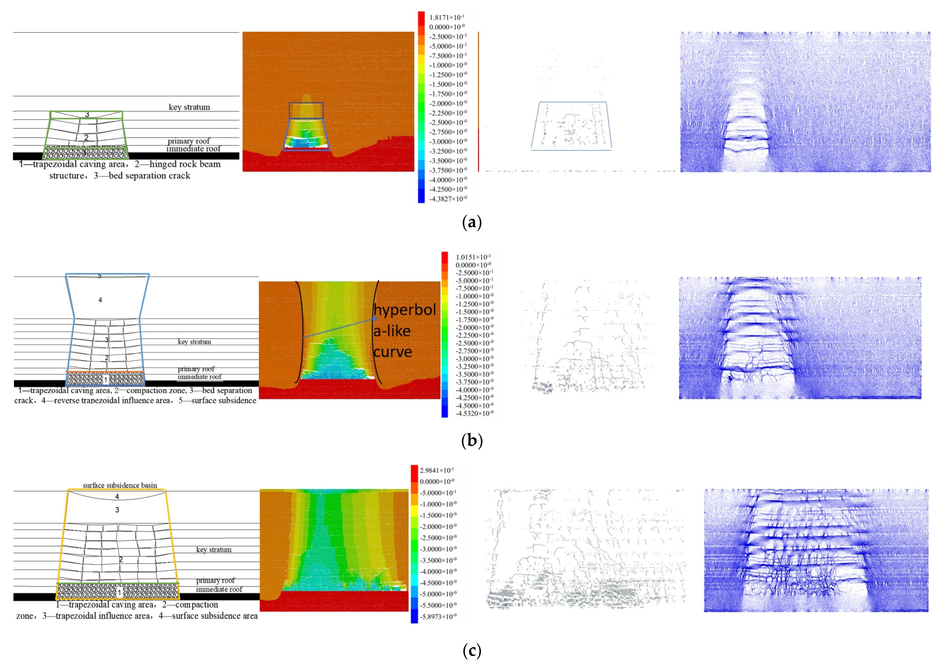
During the entire process of advancing the working face, the time evolution law of vertical displacement exhibits three distinct configurations: evolving from an early-stage “rectangle–trapezoid” distribution, transitioning to a quasi-hyperbolic pattern, and finally forming a trapezoidal field upon reaching the surface influence threshold, which tends to stabilize when the advancement reaches 250 m.
(3)
Surface subsidence characteristics initiate when the working face advances to 80 m, consistent with field observations; the subsidence basin develops smoothly into a trapezoidal shape, with maximum displacement of 4.57 m and an influence radius approximately twice the mining height.
(4)
This study demonstrates that in shallowly buried weak rock strata scenarios, surface impacts manifest with accelerated temporal characteristics owing to enhanced strata–ground coupling. The rapid goaf backfilling process effectively reduces peak subsidence magnitudes through timely stress redistribution. Roof fracturing initiates overburden delamination and collapse, establishing direct correlations between surface settlement patterns and the spatial extent of overlying strata failure along the advancement direction. Numerical simulation of progressive roof fracturing mechanisms enables predictive modeling of subsidence trough morphology, providing critical guidance for surface infrastructure protection strategies. Analysis of roof bending moment distributions under varying advancement step distances facilitates optimization of mining parameters, achieving equilibrium between operational safety and extraction efficiency. Notable limitations arise from the PFC model’s simplification of material heterogeneity—actual geological sequences containing interbedded weak layers may significantly alter fracture propagation pathways. Future investigations should incorporate stochastic mechanical parameter distributions and validate numerical predictions through field monitoring data integration, particularly regarding time-dependent deformation characteristics and fracture network evolution patterns.

Author Contributions

Conceptualization, Y.Y. and X.F.; software, G.H. and X.F.; validation, X.F., G.H., S.L. and K.Z.; formal analysis, Y.Y. and X.F.; data curation, Y.Y., X.F., G.H., S.L. and K.Z.; writing—original draft preparation, G.H., Y.Y. and X.F.; writing—review and editing, Y.Y. and X.F.; funding acquisition, Y.Y. All authors have read and agreed to the published version of the manuscript.

Funding

This work was supported by the National Natural Science Foundation of China (Grant Nos. 51404167, 42302202), the General Project of the Applied Basic Research Program of Shanxi Province (202303021211057), and the Teaching Reform and Innovation Project of Higher Education Institutions in Shanxi Province (J2019055).

Institutional Review Board Statement

Not applicable.

Informed Consent Statement

Not applicable.

Data Availability Statement

The data used to support the findings of this study are included within this article.

Conflicts of Interest

The authors declare no conflicts of interest.

References

  1. Kang, H.; Xu, G.; Wang, B.; Wu, Y.; Jiang, P.; Pan, J.; Ren, H.; Zhang, Y.; Pang, Y. Forty years of development and prospects of underground coal mining and strata control technologies in China. J. Min. Strat. Control. Eng. 2019, 1, 013501. [Google Scholar] [CrossRef]
  2. Zhang, J.; Liu, Q.; Sun, Y.; Cai, W.; Zhang, J.; Chen, C. Analysis of the stability of the surrounding rock structure in gob-side entry driving in shallow buried and thin bedrock. J. Min. Saf. Eng. 2020, 37, 647–654. [Google Scholar] [CrossRef]
  3. Yang, J.; Wu, Z.; Li, H.; Zhang, B.; Ji, W. Simulation test of water and sand burst in shallow and thin bedrock face and analysis of influencing factors. Coal Sci. Technol. 2021, 49, 1–8. [Google Scholar] [CrossRef]
  4. Wang, J.; Xu, J.; Yang, S.; Wang, Z. Development of strata movement and its control in underground mining: In memory of 40 years of Voussoir Beam Theory proposed by Academician Minggao Qian. Coal Sci. Technol. 2023, 51, 80–94. [Google Scholar] [CrossRef]
  5. Kwasniewski, M.; Lasek, S. Numerical analysis of methane migration from floor strata to a longwall face. Gór. Geoinżynieria 2007, 31, 307–322. [Google Scholar]
  6. Tomiczek, K. A brief analysis of behaviour possibility of a jointed rock mass near to longwall excavation face simulation using Distinct Elements Method (DEM) in the context of the Beam on Elastic Foundation (BEF) theory. In Proceedings of the 5th International Scientific Conference on Civil Engineering-Infrastructure-Mining, Cracow, Poland, 17–18 January 2019; Volume 106. [Google Scholar] [CrossRef]
  7. Sun, B.; Yuan, L.; Zhang, P.; Wu, R. Experimental study on photoelectric sensing of overburden movement and separation evolution in the stope under massive thick conglomerate. J. China Univ. Min. Technol. 2024, 53, 977–992. [Google Scholar] [CrossRef]
  8. Sun, J.; Cao, Z.; Wang, H.; Sun, B.; Li, Z. Full—Cycle overburden movement law of high—Stage fully—Mechanized top—Coal caving face in steeply inclined and extra—Thick coal seam. Min. Res. Dev. 2024, 44, 56–63. [Google Scholar] [CrossRef]
  9. Chang, Y.; Xue, J.; Zheng, L.; Ma, J.; Gao, X.; Zhu, Y. Research on the movement and failure laws of overlying strata in a fully—Mechanized top—Coal caving face with shallow—Buried, thick and hard bedrock. Coal Eng. 2024, 56, 144–151. [Google Scholar]
  10. Li, J.; Wang, W.; Wang, C.; Wu, X. Research on the mechanism and control of slope instability and sliding induced by overburden movement during side—Coal mining. Coal Sci. Technol. 2025, 53, 127–143. Available online: http://kns.cnki.net/kcms/detail/11.2402.td.20240407.1606.001.html (accessed on 13 February 2025).
  11. Li, B.; Chen, J.; He, B.; Pi, G. Research on the overburden movement and surface damag e characteristics of pillarless mining in shallow—Buried ultra—Thin coal seams. Coal Eng. 2024, 56, 104–111. [Google Scholar]
  12. Wang, D.; Zhang, Y.; Xie, P.; Huang, B.; Qu, L.; Wu, S.; Lin, W.; Yang, H. Research on the overburden movement law in the pseudo—Inclined stope of steeply inclined medium—Thick coal seams. Coal Eng. 2023, 55, 76–80. [Google Scholar]
  13. Nan, H.; Wang, Z. Research on the overburden movement and mine pressure behavior law of the fully—Mechanized top—Coal caving face under the disturbance of the upper coal seam. Saf. Coal Mines 2023, 54, 133–141. [Google Scholar] [CrossRef]
  14. Wu, Z.; Sun, Q.; Wang, Y. Evolution Laws of Water-Flowing Fracture Zone and Mine Pressure in Mining Shallow-Buried, Hard, and Extra-Thick Coal Seams. Appl. Sci. 2024, 14, 2915. [Google Scholar] [CrossRef]
  15. Wang, S.R.; Wu, X.G.; Zhao, Y.H.; Hagan, P. Mechanical Performances of Pressure Arch in Thick Bedrock during Shallow Coal Mining. Geofluids 2018, 2018, 2419659. [Google Scholar] [CrossRef]
  16. Xu, Z.H.; Li, Q.S.; Li, X.B. Overburden Migration and Failure Characteristics in Mining Shallow Buried Coal Seam with Thick Loose Layer. Adv. Mater. Sci. Eng. 2020, 2020, 9024751. [Google Scholar] [CrossRef]
  17. Huang, Q.; Du, J.; Hou, E.; Yang, F. Research on overburden and ground surface cracks distribution and formation mechanism in shallow coal seams group mining. Caikuang Yu Anquan Gongcheng Xuebao/J. Min. Saf. Eng. 2019, 36, 7–15. [Google Scholar]
  18. Zheng, J.; Tian, L.; Li, Y.; Xu, L.; Li, X.; Yu, F.; Wu, Z.; Sun, S. Research on the stability of composite roof in shallow -buried fully—Mechanized mining face and key monitoring technologies. Coal Eng. 2024, 56, 46–54. [Google Scholar]
  19. Lv, K.; He, F.; Xu, X.; Zhai, W.; Qin, B. Fracture characteristics and stability analysis of the main roof structure with special—Shaped load—Elastic foundation. Chin. J. Rock Mech. Eng. 2023, 42, 930–947. [Google Scholar] [CrossRef]
  20. Liu, H.; Luo, Z.; Han, Z.; Han, Z.; Chen, X.; Peng, J. Study on evolution law of overburden fracture in fully-mechanized top-coal caving face with large mining height in thick coal seam. Coal Sci. Technol. 2024, 52, 1–12. [Google Scholar] [CrossRef]
  21. Jiao, F.; Zhang, X.; Fan, Y. Research on the law of surface movement and deformation in layered paste backfill mining of thick coal seams. Coal Technol. 2024, 43, 24–28. [Google Scholar] [CrossRef]
Figure 1. Integrated rock layer bar graph.
Applsci 15 06036 g001
Figure 2. Roof stress analysis diagram.
Applsci 15 06036 g002
Figure 3. The basic top bending moment curve.
Applsci 15 06036 g003
Figure 4. Schematic diagram of the model.
Applsci 15 06036 g004
Figure 5. Early collapse diagram.
Applsci 15 06036 g005
Figure 6. Overburden rock caving process diagram.
Applsci 15 06036 g006
Figure 7. Temporal evolution of displacement.
Applsci 15 06036 g007
Figure 8. Surface subsidence diagram.
Applsci 15 06036 g008
Figure 9. Dynamic evolution diagram of maximum surface subsidence value.
Applsci 15 06036 g009
Figure 10. Evolution diagram of the overburden rock fracture stage: (a) the initial stage; (b) the intermediate stage; (c) the final stage.
Applsci 15 06036 g010
Table 1. Mechanical parameters of overburden rock.
LithologyElastic Modulus /GPaTensile
Strength
/MPa
Cohesion
/MPa
Internal Friction Angle
Poisson Ratio
Sandy mudstone3.22.13.5250.31
Packsand4.22.34.4220.24
Mudstone2.51.32.2240.17
Medium sandstone4.22.95.9260.27
No. 2-1 coal0.50.11.5220.24
Limestone27.76.245.812.60.3
Disclaimer/Publisher’s Note: The statements, opinions and data contained in all publications are solely those of the individual author(s) and contributor(s) and not of MDPI and/or the editor(s). MDPI and/or the editor(s) disclaim responsibility for any injury to people or property resulting from any ideas, methods, instructions or products referred to in the content.

