Abstract
Curved-spoke wheels have been proposed as an effective way to overcome stair-like obstacles with smooth, rotation-only motion. However, when the wheel’s contact point shifts, discontinuous changes in its radius of curvature cause abrupt drops in the robot’s linear speed, often leading to reduced payload stability and slip. As a result, maintaining reliable stair climbing becomes more difficult. At higher speeds, these sudden changes become stronger, further reducing dynamic stability. To address these issues, we propose a passive Compliant Spiral Torsional Suspension (C-STS) attached to the wheel’s drive axis. Through camera-based marker tracking, we analyzed wheel trajectories under various stiffness and speed conditions. In particular, we define the deceleration caused by the velocity drop during contact transitions as our dynamic stability metric and demonstrate that the C-STS significantly reduces this deceleration across low-, medium-, and high-speed climbing, based on comparisons both with and without the suspension. It also raises the average velocity, likely due to a brief release of stored elastic energy, and lowers the net torque requirement. Our findings show that the proposed C-STS greatly improves dynamic stability and suggest its potential for enhancing stair-climbing performance in curved-wheel-based robotic systems. Furthermore, our approach may extend to other reconfigurable wheels facing similar instabilities.
1. Introduction
Service robots play an increasingly vital role in various applications, from domestic assistance to industrial logistics. For these robots to perform a wide range of tasks, they must be capable of negotiating everyday obstacles, among which stairs pose one of the most challenging barriers. Researchers have long sought ways to enable reliable stair climbing, leading to diverse approaches that balance stability, complexity, and versatility.
A track-based system [1,2,3,4,5,6] is a commonly adopted approach to negotiate rough or soft terrain. Its wide contact area allows the robot to move over loose or uneven surfaces with relative ease, distributing weight to reduce sinking and maintain traction. However, tracked platforms are often bulky and heavy, making them cumbersome to maneuver in confined indoor spaces. Furthermore, their reliance on skid steering can damage floor surfaces and is generally unsuitable for precise navigation, especially in narrow corridors or tight corners.
In contrast, legged robots [7,8,9,10,11,12,13] can navigate a wide range of terrains by mimicking biological locomotion. Their multi-jointed limbs enable them to step over obstacles and maintain balance on uneven ground. Yet, this versatility comes at the cost of increased mechanical complexity and demanding control algorithms. As a result, the number of actuators and sensors required for smooth-legged motion can drive up both cost and system fragility.
Another line of research, the wheel-linkage mechanism [14,15,16,17,18,19], attaches linkages to circular wheels to effectively overcome certain obstacles by distributing loads. While promising, its performance on stairs can be heavily influenced by the shape of the stair’s vertical face. Moreover, it depends strongly on friction, often causing slip during ascent or descent.
Curved-spoke wheels [20,21,22,23,24,25] have been proposed as a simpler alternative, where a specially contoured wheel can ascend stairs using only rotational motion. In previous studies [21], mechanical stoppers were introduced to address slip issues at the instant the contact point shifts from one step to the next. While these measures showed partial success, they did not fully resolve the underlying dynamic effects, such as abrupt velocity fluctuations due to the changing radius of curvature.
Although curved wheels can generate a smooth center-of-rotation (COR) path, the linear velocity of the robot body tends to fluctuate. This fluctuation arises from the abrupt changes in the radius of the curvature, especially at the exact moment the contact point shifts from one part of the wheel to another. In practice, these discontinuities can lead to instability of any payload carried by the robot, making reliable stair climbing difficult. The situation worsens at higher speeds, where the dynamic impact of these abrupt changes is amplified, further compromising the robot’s stability on the stairs.
In addition to purely mechanical approaches, some researchers have attempted to reduce fluctuations in the wheel’s COR linear velocity by calculating the required wheel rotation speed in reverse and then applying active velocity control [25]. Although this method can stabilize stair climbing to some degree, its effectiveness has been demonstrated only at extremely low speeds—around 0.01 m/s—due to control-cycle constraints and limited motor output. Such a slow speed is impractical for most real-world scenarios that demand more agile stair-climbing performance. Consequently, an alternative strategy that does not rely solely on low-speed control is needed to ensure dynamic stability and efficient climbing.
Motivated by the need to improve dynamic stability during stair climbing, this work presents a Passive Compliant Spiral Torsional Suspension (C-STS) for curved-spoke wheels (Figure 1). The suspension stores energy during ground rolling and releases it at the critical moment of contact transition, assisting the wheel’s ascent and mitigating abrupt deceleration. In addition, by introducing compliance between the motor and wheel axes, it also helps the robot’s main body preserve its inertia, thereby improving the system’s dynamic stability.

Figure 1.
Conceptual overview of the proposed passive compliant spiral torsional suspension (C-STS) applied to a curved-spoke wheel. Blue arrows indicate changes in velocity before and after the climbing transition.
The remainder of this paper presents a kinematic analysis of curved wheels to investigate their dynamic effects, describes the design of the proposed suspension, details the experimental setup used to evaluate its performance across various stiffness and speed conditions, and explores how this approach can address key challenges in curved-wheel stair climbing. By offering a solution that does not depend solely on low-speed control, our work lays the groundwork for more robust and efficient stair-climbing mechanisms in real-world applications.
2. Kinematic Analysis of Curved-Spoke Wheel
2.1. Definition of the Curved-Spoke Wheel
Figure 2 illustrates the geometry of the curved-spoke wheel and shows how it climbs from step to step on a stair with tread width and riser height . As shown, the wheel consists of three curved spokes, each defined as a segment of an arc with a radius and a central angle . In addition, the shape of the curved-spoke wheel is characterized by two parameters, and .
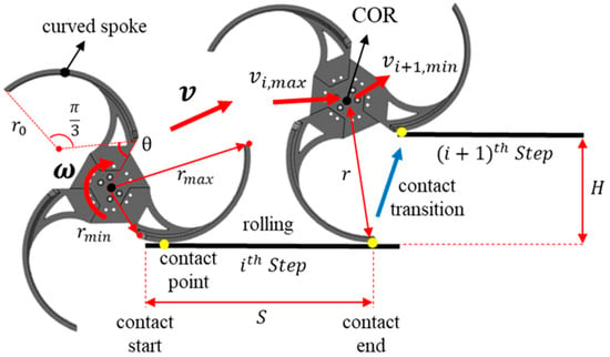
Figure 2.
Configuration and rolling motion of curved-spoke wheel while climbing the stair from step to step The red arrow labeled indicates the CoR’s general velocity vector, while denotes the peak velocity just before contact transition and the minimum velocity after transition.
The curved-spoke wheel moves by rolling on the ground. If we define the instantaneous curvature radius (i.e., the effective radius) as the distance between the wheel’s CoR and the spoke–ground contact point, then increases continuously from to during rolling. Once the curvature radius reaches its maximum, the wheel makes a contact transition to the next stair step. By repeating this process, it progresses up the stairs.
2.2. MATLAB Simulation on Curved-Spoke Wheel
Using MATLAB R2023a we conducted a kinematic analysis and simulation of the curved-spoke wheel climbing a representative stair. The stair dimensions were chosen as , which are commonly found in everyday environments. Consequently, under a constant angular velocity, the CoR’s linear velocity for the curved-spoke wheel follows the trend shown in Figure 3. The wheel’s rotational speed and the CoR’s linear velocity exhibit a nonlinear, discontinuous relationship. Over the course of stair climbing, changes in the CoR’s linear velocity can be broadly divided into two phases. The first phase, continuous contact state (CCS, (2)→(3)), occurs as increases continuously from to while the wheel rolls forward. The second phase, discontinuous contact state (DCS, (3)→(4)), takes place momentarily when the contact point shifts to the next step, causing to drop abruptly from to .
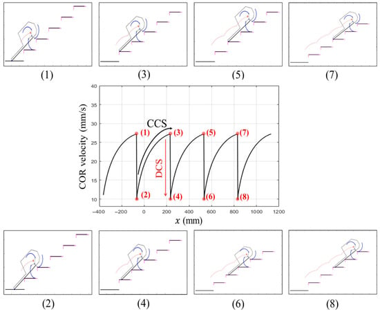
Figure 3.
Simulation snapshots illustrating the stair-climbing dynamics. Each ascending phase ((1), (3), (5), and (7)) features a maximum rotational radius, while the subsequent frames ((2), (4), (6), and (8)) demonstrate the abrupt decrease in radius due to discontinuous radius of curvature of the spoke. The continuous contact state (CCS) refers to the wheel rolling smoothly from to , whereas the discontinuous contact state (DCS) occurs momentarily at the contact transition, leading to a sudden velocity drop.
During the continuous contact state (CCS), as increases continuously, the CoR’s linear velocity likewise rises in a smooth manner. In contrast, during the discontinuous contact state (DCS), abruptly drops from to , causing the wheel’s linear velocity to plunge from its pre-transition peak to . The drop in velocity at this point is given by . Consequently, when the curved-spoke wheel climbs the stairs, a discontinuity in the curvature radius arises precisely at the instant the contact point transitions, and the CoR’s linear velocity decreases discontinuously. In reality, however, due to inertia, the CoR cannot instantaneously slowdown, which can lead to payload instability or slip at the floor–wheel interface.
To examine how the magnitude of this velocity discontinuity depends on the wheel’s speed and stair dimensions, we compared —the discontinuity occurring during the transition from one stair step to the next—under various rotation speeds and stair sizes. Table 1 summarizes the conditions tested: Condition 1 (C1) increases the wheel’s angular velocity while keeping the stair dimensions fixed, whereas Condition 2 (C2) modifies the stair height while holding the wheel’s angular velocity constant. The resulting trends in the CoR’s linear velocity for each condition are shown in Figure 4 and Table 2.

Table 1.
Two conditions of the simulation.
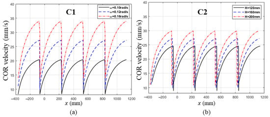
Figure 4.
Simulation results of CoR velocity. (a) Velocity profiles at different drive angular velocities (ω = 0.10, 0.12, and 0.16 rad/s) with a fixed stair dimension ( × = 300 mm × 160 mm). (b) Velocity profiles for different stair heights ( = 120, 160, and 200 mm) under a fixed drive angular velocity (ω = 0.12 rad/s). C1 refers to changing the wheel’s angular velocity while fixing the stair dimensions, and C2 refers to varying the stair height under a constant angular velocity.

Table 2.
The velocity decrease during DCS obtained from C1 and C2.
From C1, we observe that when the wheel’s angular velocity increases at a fixed stair size, the velocity decrease during the DCS phase also rises. Notably, as increases, not only does grow but also both the minimum and maximum velocities increase, as shown in Figure 4a. The C2 results, presented in Figure 4b, indicate that at a fixed angular velocity, grows larger when the stair height is increased. These findings demonstrate that the nonlinear relationship between the wheel’s rotation speed and the CoR’s linear velocity becomes more pronounced—and thus more destabilizing—when angular velocity or obstacle size increases. In the following section, we introduce a compliant torsional suspension designed to mitigate these adverse dynamic effects.
3. Design of Passive Torsional Compliant Suspension
3.1. Dynamic Stability Metrics for Curved-Spoke Wheel
As introduced in Section 2.2 (Figure 3), the theoretical analysis suggests that the wheel’s center of rotation (CoR) can drop from its maximum to minimum velocity instantaneously during the DCS interval, resulting in an infinite deceleration. However, in real-world conditions, inertia and friction cause the velocity to decrease over a finite duration, producing a finite deceleration (Figure 5). This deceleration imposes inertial forces on the robot’s main body and payload, which in turn can undermine dynamic stability.
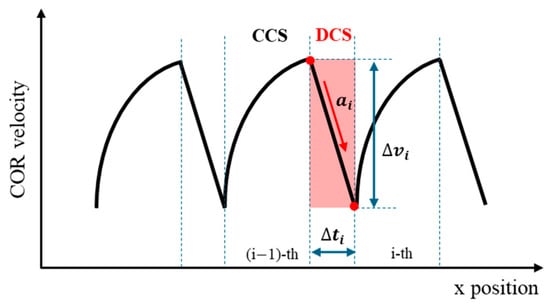
Figure 5.
Illustrative depiction of a real-world CoR velocity profile showing DCS interval and key stability metrics. The red-shaded region highlights the DCS phase, where indicates the duration, the velocity drop, and the deceleration magnitude.
Because acceleration (or deceleration) naturally captures the rate at which velocity changes—and has long served as a standard performance metric for dynamic stability in robots and vehicles [26,27,28]—we adopt it here as our primary measure of stability during the DCS phase. This straightforward approach aligns well with how abrupt deceleration spikes can undermine control and increase the risk of slip or rollover, especially on uneven terrain. Thus, we define the deceleration in the DCS interval to quantify how severely the CoR velocity is forced to drop, which we regard as a direct indicator of dynamic instability.
The slope of the velocity profile during the DCS phase, reflecting how quickly the velocity changes.
Where and are defined as follows:
The duration over which the CoR velocity rapidly decreases during the DCS phase.
The total velocity drop from the previous step(i − 1)’s maximum to the current step(i)’s minimum.
In addition, while the robot ascends N steps, we track the CoR’s mean velocity and standard deviation as supplementary metrics to compare overall climbing performance. A higher mean velocity with lower variability implies faster and more stable stair-climbing behavior.
Average CoR velocity during -step climbing.
The degree of how tightly the CoR velocity is clustered around the mean velocity during steps.
3.2. Concept of Compliant Spiral Torsional Suspension (C-STS)
The curved-spoke wheel undergoes sudden deceleration whenever its contact point transitions to a new step. As discussed earlier, this abrupt velocity change at the wheel’s center of rotation (CoR) can compromise dynamic stability, particularly because the effective mass M concentrated at the CoR attempts to maintain its inertia. Figure 6 contrasts the conventional wheel (a1–a3)—which experiences abrupt deceleration—with the proposed wheel equipped with a torsional spring (b1–b3) that deforms to mitigate such instability.
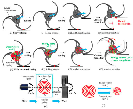
Figure 6.
Illustration of the proposed torsional suspension’s working principle and design space. (a) Conventional curved-spoke wheel (a1–a3): During obstacle climbing and contact transitions, the wheel’s center of rotation (CoR) experiences an abrupt deceleration, potentially causing instability. (b) Curved-spoke wheel with torsional spring (b1–b3): At the moment of contact transition, the torsional spring deforms to mitigate sudden deceleration and improve dynamic stability. (c) Simplified schematic of the spiral suspension mechanism: The difference in angular displacement between the motor ) and the wheel ) is absorbed by the spiral spring. (d) Energy storage and release through In addition, the blue arrow at the CoR denotes the velocity’s magnitude and direction, while the green arrow in (b,b1,b3) indicates the torsional spring’s deflection direction.
To reduce these nonlinear velocity fluctuations, we introduce torsional compliance between the motor shaft () and the wheel shaft (). During normal rolling on the ground, the spiral spring (see Figure 6c) deflects as the wheel rotates relative to the motor, thereby storing energy. When the contact point shifts, the wheel would otherwise decelerate instantly, but here, it is free to rotate slightly further relative to the motor. This motion releases a portion of the stored spring energy (Figure 6d), helping to propel the wheel upward and maintain the CoR’s inertia.
For this study, we focus on the magnitude of the CoR’s velocity, treating its trajectory as if it were nearly linear. In reality, the velocity’s direction also changes abruptly at contact transitions. However, we assume these directional changes are relatively small or gradual compared to the dominant effect of speed reduction. Since the CoR moves in a direction that increases the wheel’s potential energy, the spiral spring’s torque input is crucial for compensating this energy requirement.
By design, the C-STS is deformed during rolling (increasing ) and then returns some of that energy when the wheel attempts to decelerate more than the motor shaft. In other words:
- Energy Storage: As the motor rotates further or faster than the wheel, increases, and the spring deflects, storing energy.
- Energy Release: When contact transitions occur, the wheel can briefly rotate relative to the motor shaft in the opposite direction, reducing and releasing stored elastic energy.
- Maintaining Inertia: By allowing the wheel to rotate somewhat independently of the motor shaft, the compliance helps the CoR preserve part of its original velocity, avoiding an extreme deceleration spike and thus improving dynamic stability.
Hence, C-STS functions by absorbing sudden rotational differences between the motor and the wheel, and then releasing that energy at critical moments, softening the rapid velocity drop that would otherwise destabilize the system.
A compliant spiral mechanism was selected as an alternative due to its distinct advantages. First, by forming the entire mechanism as a single compliant structure, it replaces multiple hinges, links, and bearings, thereby reducing component count and minimizing friction or backlash. In addition, the spiral geometry facilitates a gradual elastic deformation under external loads, providing enhanced energy absorption and dispersion. Moreover, it is well-suited for additive manufacturing processes such as 3D printing, allowing for simplified design modifications and fabrication. Taken together, these benefits make the compliant spiral mechanism an effective choice for achieving both the required strength and flexibility, particularly in applications involving rotational or torsional motions.
3.3. Design of Compliant Spiral Torsional Suspension
An exploded view of the C-STS mechanism developed in this study is shown in Figure 7. It primarily consists of the motor, the compliant spiral suspension module, the wheel, and a set of connecting components. As illustrated in Figure 8a, the compliant spiral suspension is composed of two main parts: an inner ring and an outer ring. The inner ring features a slot (Figure 8b) where the inner shaft holder is attached, which—together with a key—links the motor shaft to the suspension. Thus, the inner ring receives torque directly from the motor. The outer ring has six holes (Figure 8a), three of which are used to connect it to the outer hub, which in turn is fastened to the wheel hub via the outer shaft holder. In other words, the outer ring interfaces with the wheel, transmitting external loads to the suspension.
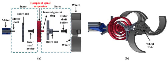
Figure 7.
Configuration of the compliant spiral suspension system. (a) Exploded top view. (b) Exploded side view.
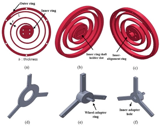
Figure 8.
Configurations of key components of the suspension system. (a) Front view of the compliant spiral suspension. (b) Front side view of the suspension. (c) Back side view of the suspension. (d) Inner hub. (e) Front side view of the outer hub (f) Back side view of the outer hub.
To prevent deformations in any direction other than the torsional axis, two additional design features were implemented. First, to keep the inner ring from deforming radially, an inner-alignment ring was added to the rear of the inner ring (Figure 8c), and an inner-adapter hole (Figure 8f) was added to the rear of the outer hub. These two parts fit loosely together, allowing relative rotational motion between the compliant spiral suspension and the hub assembly. Second, to constrain deformation along the motor’s rotational axis, an inner hub was attached to the suspension’s face that couples with the motor, thereby blocking the inner ring from moving axially. As a result, the compliant spiral suspension is free to deform primarily in the torsional direction.
In this study, we used PLA (polylactic acid) as the primary material, with an elastic modulus of . Our goal was to support a 6 kg curved-wheel robot, which requires an estimated 0.76 N·m of static torque under worst-case stair-climbing conditions. To ensure safety, we set a factor of safety of five relative to the PLA’s bending strength (. This guided the initial geometry for our spiral spring, characterized by three key parameters: thickness t, length L, and width b.
From practical trial-and-error, we identified a baseline that effectively moderated velocity fluctuations: t = 5 mm, L = 827.28 mm, and b = 15 mm. We used the classic flat spiral spring stiffness formula,
We calculated a theoretical stiffness of approximately 0.661 . Two other variants were defined by modifying the thickness while keeping b = 15 mm and L = 1136.2 mm:
Low-stiffness suspension: t = 4 mm,
High-stiffness suspension: t = 6 mm,
All three designs respected the safety margin criteria for a 6 kg load, with the intention of comparing different levels of torsional compliance.
To confirm the actual stiffness, we measured the angular deflection by applying a 1–2 kg load at a radius of 0.11 m from the spiral spring’s center. We then derived the experimental from the resulting torque–angle relationship. For instance, the baseline suspension (t = 5 mm, L = 827.28 mm) yielded an empirical stiffness of , notably less than the theoretical . Similarly, the low-stiffness and high-stiffness versions measured at and , respectively, again falling below their corresponding theoretical values.
We attribute the lower-than-expected stiffness primarily to two factors. First, even with 100% infill, small voids or imperfections can appear within the PLA structure, reducing its effective strength and stiffness and causing the actual stiffness to fall short of the theoretical value, which assumes a perfectly solid, isotropic beam. Second, a classic spiral spring formula presumes a continuous rectangular cross-section throughout, whereas our C-STS diverges from this ideal shape—for instance, the central region includes a ϕ30 mm circular slot for the inner shaft holder, deviating significantly from a flat rectangular beam. Moving forward, we plan to develop a large-deformation analysis using a pseudo-rigid-body model to better capture the compliant aspects of the C-STS’s geometry, incorporating the actual cross-sectional profile and 3D-printed structure to derive a more robust theoretical stiffness value that closely matches real-world measurements.
Although these factors largely concern the spiral portion of the suspension, the wheel’s spokes could also introduce additional compliance. To verify the effect of spoke compliance, we performed a SolidWorks 2024 simulation (Figure 9) in which the wheel’s center of rotation (CoR) was fixed and a 20 N normal load was applied at three radial points (P1, P2, and P3) on the spoke. Using polylactic acid (PLA) properties, by measuring the resulting deformation, we derived the spoke’s torsional stiffness ( at each point and combined it with that of the spiral spring to obtain the total stiffness (. Table 3 compares to the spiral spring stiffness . Our results indicate that, at most, the spoke contributed only 1.7% to the overall torsional stiffness—becoming even less significant under typical loading conditions. In particular, P3 (corresponding to the contact location at transition) exhibited a slightly higher stiffness than P1 or P2, yet its effect remained negligible compared to the spiral spring. Consequently, assuming a rigid spoke in our primary model does not compromise accuracy.
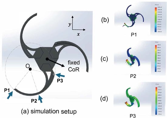
Figure 9.
Stiffness simulation setup and results: (a) simulation setup showing the wheel’s CoR fixed and a 20 N normal load applied, (b) P1, (c) P2, and (d) P3 represent the three radial points on the spoke where the load is applied.

Table 3.
Spoke torsional stiffness calculation based on SolidWorks simulation.
4. Experiments
4.1. Experimental Setup
4.1.1. Experimental Equipment
To evaluate the performance of the proposed C-STS mechanism, we integrated it into a curved-spoke wheel and constructed a test platform, as shown in Figure 10b. For comparison, a platform without the suspension was also built (Figure 10a). The curved-spoke wheel geometry used in the experiment was defined by and Both platforms share a symmetrical design, featuring two DC motors, motor drivers, a single MCU, a Li-Po battery, and a joystick controller. The test stairway consists of four steps, each measuring , as shown in Figure 10c. To ensure that only the effect of the C-STS mechanism on climbing performance is observed, the platform’s tail was extended to 1200 mm, preventing it from contacting the steps during ascent. A marker was attached to the wheel’s center of rotation (CoR), and 4K video at 60 fps was recorded for trajectory analysis. Table 4 summarizes the specifications and equipment used in these experiments.
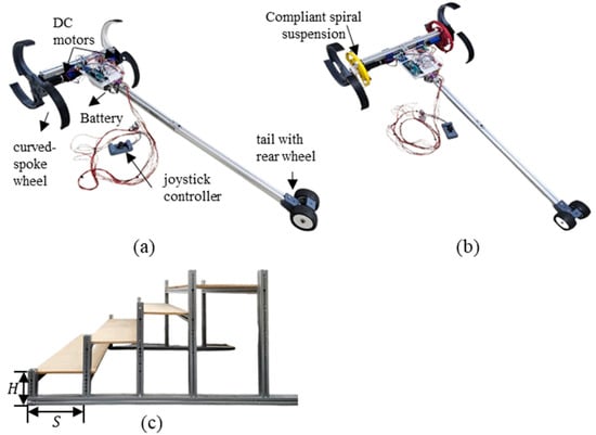
Figure 10.
Experimental equipment. (a) Basic (without suspension) platform configuration. (b) Compliant (with suspension) platform configuration. (c) Stair used on the experiment ().

Table 4.
Experimental equipment and specifications.
4.1.2. Experimental Scenarios
The primary objective of this study is to determine how the proposed C-STS mechanism affects the stair-climbing performance of a curved-spoke wheel and to validate its effectiveness in mitigating abrupt deceleration during the DCS phase. To that end, we measured the wheel’s CoR linear velocity through video capture and subsequent trajectory analysis, comparing the results for both the suspension-equipped platform and the one without it. In all tests, the platform remained stationary at a point away from the first step, ensuring the wheel’s center of rotation started from a consistent initial position.
In this experiment, we used three different suspensions with torsional stiffness values of , , and . For convenience, we refer to them as the low-k suspension, middle-k suspension, and high-k suspension, while the configuration without a suspension is labeled basic. Table 5 summarizes the experimental scenarios: S1 involves a robot without any suspension (basic) climbing the stairs at low, medium, and high speeds. S2, S3, and S4 use the low-k, middle-k, and high-k suspensions, respectively, under the same three speed conditions. These different speeds were achieved by adjusting the PWM inputs to the motor driver. To ensure consistent data across all scenarios, each case was repeated three times, yielding a total of 36 stair-climbing trials.

Table 5.
Four Stiffness and three drive angular velocity conditions.
4.1.3. Systematic Workflow for Data Acquisition and Processing
In each trial, we recorded the stair-climbing motion of the robot—fitted with a marker on the wheel’s CoR—using a video camera. We then processed every dataset according to the workflow illustrated in Figure 11.
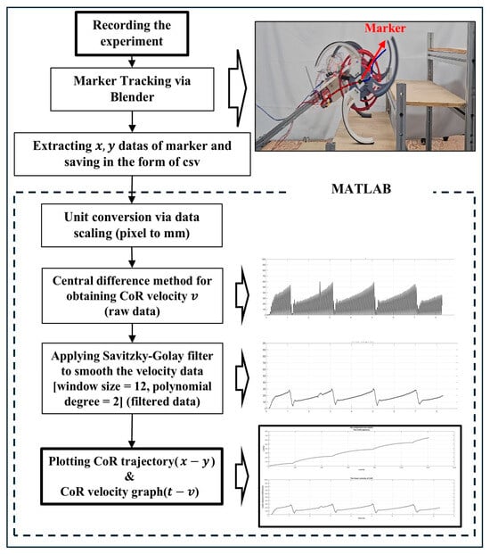
Figure 11.
Data processing pipeline for extracting CoR trajectory and velocity from marker tracking.
First, each trial was recorded on video as the robot ascended the stairs, and the video file was saved. Next, we used Blender 4.3 software to track the marker placed on the wheel’s CoR through marker tracking techniques, extracting the position data for each tracked frame and saving them to a CSV file. We then imported these pixel-based data into MATLAB, where they were scaled to millimeters by leveraging the periodicity of the wheel’s trajectory. To compute the velocity from these scaled discrete points, we performed numerical differentiation using a forward finite-difference method, yielding the raw velocity data as described below.
Since the video was recorded at 60 frames per second (FPS), the sampling time was . Due to the nature of finite differences, performing numerical differentiation at a sampling rate of 60 fps (about 0.016 s) can produce velocity data that appear noisy. To mitigate this, a filter must be applied to smooth the data. Among various filtering techniques, we selected the Savitzky–Golay filter because it preserves the original trend of the data while preventing large deviations from the actual values. After these processing steps, each experiment yielded two final outputs: an trajectory graph of the wheel’s CoR and a corresponding time–velocity plot.
Meanwhile, the process shown in Figure 11 can be viewed as converting pixel-based image coordinates into real-world coordinates measured in millimeters. However, camera-based image analysis inherently involves distortion errors, because lens-induced effects prevent perfect alignment between image coordinates and physical coordinates. Normally, correcting these errors requires determining the camera parameters and performing a camera calibration procedure.
In this experiment, however, the robot was filmed from a distance of about 2 m, capturing its 2D motion. As summarized in Table 4, the camera used had a field of view (FOV) of , and the robot’s motion remained within roughly of the center of the frame. Under such conditions—even with a moderately wide-angle lens—lens distortion errors typically remain below 2%. Consequently, a dedicated camera calibration was deemed unnecessary, and we were able to achieve sufficiently meaningful results without additional distortion compensation.
To verify that the error is indeed negligible, we compared the marker-tracked CoR trajectory with the simulated CoR trajectory of the curved-spoke wheel ascending the stairs, as shown in Figure 12. The mean error in the -direction between the two trajectories was 5.96 , with an RMS error of 7.08 . Over the 0–585 mm range of motion in the -direction, these values correspond to error rates of approximately 1.02%, respectively. This minor discrepancy may arise from slight lens distortion, minor inaccuracies in marker placement, or the purely kinematic assumptions of the simulation—excluding inertia, friction, and motor torque variations. Nonetheless, we considered the error sufficiently small for evaluating the suspension’s impact and performance.
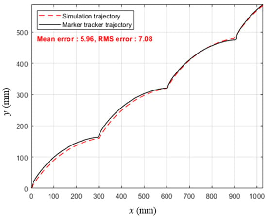
Figure 12.
Trajectory comparison of the wheel CoR between simulation and marker tracking data.
4.2. Experimental Results
A total of 36 stair-climbing experiments were conducted, repeating the low-, medium-, and high-speed scenarios three times each, as outlined in Table 5. Figure 13 shows representative images from the basic and high-k configurations (S1 and S4). Below, Figure 14 shows the wheel’s CoR trajectory and its velocity profile for each scenario at different operating speeds. Each scenario was tested three times, and representative graphs are presented here. For PWM duty ratios of 20%, 40%, and 60%, the measured average angular velocities during a single-step climb were 3.2, 8.5, and 13 rad/s, respectively.
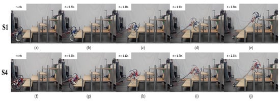
Figure 13.
Stair-climbing experiments for scenarios S1 (a–e) and S4 (f–j).
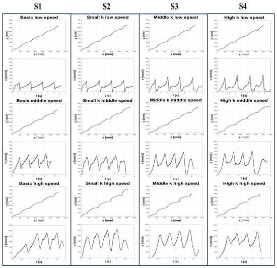
Figure 14.
Representative CoR trajectories and linear velocity profiles for four Scenarios (S1–S4). Each was repeated three times. (Low speed: ω = 3.2 rad/s, middle speed: ω = 8.5 rad/s, high speed: ω = 13 rad/s, low k: kt = 0.206 N∙m/rad, middle k: kt = 0.547 N∙m/rad, high k: kt = 0.909 N∙m/rad).
In the simulation, the DCS appeared as an abrupt velocity drop, but the experimental data in Figure 14 show—consistent with Figure 5—that it unfolds over a finite time and maintains a relatively steady slope. This observation supports defining dynamic stability in the DCS phase by using the acceleration , as it directly reflects how rapidly the velocity changes under inertial forces, providing a clear indicator of the system’s ability to cope with sudden transitions.
For each DCS interval, one value each of is obtained. Because the robot passes through three steps (steps 1, 2, and 3), three sets of these parameters are collected, one for each DCS period. The average value is then defined as the mean of the three corresponding values from steps 1, 2, and 3. Table 6, Table 7 and Table 8 summarize the time interval, velocity gap magnitude, and acceleration for all four scenarios (basic, low-k, middle-k, and high-k suspensions) under low-speed, medium-speed, and high-speed conditions, respectively. Figure 15 presents bar charts of the average values for , and across all four stiffness levels under each speed condition.

Table 6.
Measured values of time interval, velocity gap magnitude, and acceleration for low speed and each step under four stiffness conditions.

Table 7.
Measured values of time interval, velocity gap magnitude, and acceleration for middle speed and each step under four stiffness conditions.

Table 8.
Measured values of time interval, velocity gap magnitude, and acceleration for high speed and each step under four stiffness conditions.
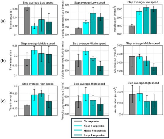
Figure 15.
Average values of time interval, velocity gap magnitude, and acceleration during contact transition in DCS for scenarios S1–S4. (a) Low-speed (rad/s) results. (b) Middle-speed ( rad/s) results. (c) High-speed ( rad/s) results.
Table 9 summarizes the average velocity and standard deviation across all speed conditions and scenarios. Figure 16 and Figure 17 present these results in bar-chart form.

Table 9.
Values of mean velocity and standard deviation of velocity for three drive speeds and scenarios S1–S4.
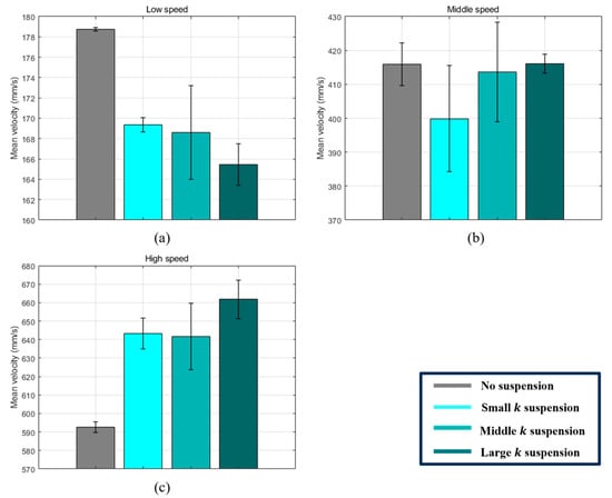
Figure 16.
Graphs of mean velocity values calculated from the first to third DCS intervals (S1–S4) (a) Low speed. (b) Middle speed. (c) High speed.
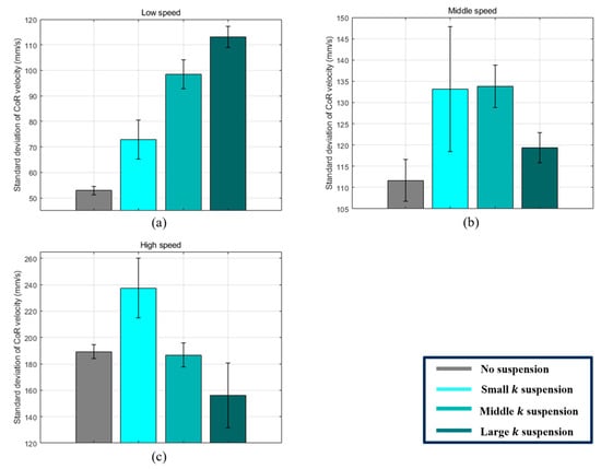
Figure 17.
Graphs of standard deviation of CoR velocity values calculated from the first to third DCS intervals (S1–S4) (a) Low speed. (b) Middle speed. (c) High speed.
5. Analysis and Discussion
This study defines abrupt deceleration at the contact transition (DCS) as a primary metric of dynamic stability for a curved-spoke wheel. Our passive spiral torsional suspension (C-STS) aims to store and release energy between the motor shaft and the wheel shaft, thereby mitigating sudden velocity drops. Below, Section 5.1 addresses DCS-specific stability, while Section 5.2 discusses overall climbing performance metrics.
5.1. DCS-Related Dynamic Stability
- (1)
- Reduced Deceleration at Medium/High Speeds
The experimental results in Figure 15b,c and Table 7 and Table 8 show that, under medium- and high-speed conditions, a higher suspension stiffness consistently led to a noticeable reduction in deceleration during the DCS phase—for example, middle-k and high-k achieved average decreases of 9.17% and 22.12% at mid-speed and 23.74% and 21.8% at high speed, respectively, compared to the basic configuration. Notably, middle-k sometimes matched or surpassed high-k at higher speeds, suggesting that an overly stiff spring may release its energy at a slightly off-peak timing, whereas a moderate stiffness better aligns with the wheel’s inertia and the contact transition moment. Consequently, the spiral spring can significantly counteract sudden velocity drops during the DCS interval, provided the spring stiffness, speed, and other conditions in a curved-spoke wheel are well matched. We hypothesize that this arises because the spring’s deformation and release timing coincide more effectively with the required torque and inertial forces, though further studies would be needed to confirm the exact mechanism.
- (2)
- Limited Benefits of Low-k
Under the same mid/high-speed conditions, the low-k suspension produced deceleration values comparable to basic (ranging from −1.94% to +0.43%). Our preliminary evaluation of and suggests that the velocity gap may either grow while the transition extends, or vice versa, effectively canceling out in terms of overall deceleration. This phenomenon likely arises because low stiffness cannot provide sufficient torque offset at the critical instant when the CoR velocity needs support, leading to only minimal net improvement in dynamic stability.
- (3)
- Negative Effects at Low Speeds
Table 6 shows that low-k, middle-k, and high-k each produced deceleration values 30–37% higher than basic at low speeds, indicating that stiffer springs paradoxically worsened dynamic stability in this regime. A key factor appears to be premature spring “unwinding” when the wheel rotates slowly, briefly accelerating the CoR before the actual contact transition. During the rolling process (Figure 18a,b)), the required torque typically rises and then falls, and at low speeds, this fluctuation can trigger undesirable energy release just prior to contact transition—especially for stiffer springs that store more energy under the same angular displacement (Figure 14 shows that lower-speed runs with higher stiffness often reach a larger maximum velocity). As a result, the CoR velocity spikes at the wrong moment, and little or no energy remains to cushion the actual DCS. We occasionally observed short stops at the next stair edge (S2–S4, Figure 14), suggesting the wheel momentarily loses forward motion when it lacks sufficient to deliver the needed torque for climbing.
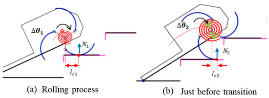
Figure 18.
Comparison of required torque and spring deflection during the curved-spoke wheel’s climbing process. Here, and denote the distances from the contact point to the wheel’s CoR, while and represent the normal forces acting on the wheel at each contact point.
By contrast, faster rotation shortens the window in which the spring can misfire its energy, making compliance more beneficial at higher speeds (as evidenced by Figure 15c, where low stiffness was not detrimental in mid/high-speed scenarios). Moreover, at higher speeds, inertia helps the wheel bypass such stalls, and the spring’s compliance more effectively reduces deceleration ().
5.2. Overall Performance and Mean Value Comparison
As shown in Table 9, the mean velocity under low-speed conditions was highest in the basic configuration (i.e., without a suspension). This outcome aligns with the earlier observation that, at low speeds, the wheel tends to momentarily stop when its spoke contacts the next step edge, because the suspension fails to release energy in time. These brief stops ultimately lower the overall average velocity.
Under medium-speed conditions, except for the low-k case, the mean velocities of the basic and suspension-equipped platforms were fairly similar. In contrast, at high speeds, all suspensions delivered mean velocities about 10% higher than those of basic; notably, the high-k suspension exceeded basic by 11.6%. This result suggests that, at sufficiently high speeds, a high-stiffness spiral suspension can both increase climbing speed and improve dynamic stability compared to basic.
Next, the standard deviation of velocity indicates how tightly the CoR velocity is clustered around the mean. A smaller reflects less fluctuation and thus higher dynamic stability. According to Table 9, basic had the smallest standard deviation at low and medium speeds, but under high-speed conditions, the high-k suspension showed a 17.5% reduction in compared to basic. This finding suggests that, at higher speeds, increasing suspension stiffness yields a more stable velocity distribution. In summary, a high-stiffness suspension at high speeds can achieve both a higher average velocity and a lower velocity fluctuation, leading to improved dynamic stability overall.
5.3. Qualitative Hypotheses and Future Work
Although slip was not observed in our experiments, the measured reduction in DCS deceleration suggests that conditions leading to slip (i.e., abrupt velocity changes) are effectively mitigated. While Section 3.1 and Section 3.2 primarily introduce the conceptual design principles of the C-STS rather than a purely theoretical model, they still elucidate how lowering deceleration in the DCS phase can lessen the likelihood of exceeding friction limits and hence reduce the risk of slip.
While our explanations are consistent with general mechanical principles—concerning inertia, timing, and torque demands—they remain qualitative. More rigorous validation, possibly involving multi-body simulations, torque-sensor data, or additional sensor instrumentation, would help quantify each proposed factor. Nevertheless, the recurring improvement observed in mid/high-speed conditions under C-STS, alongside its apparent drawbacks at low speed, provides critical insight for future design refinements. For instance, if one seeks to harness C-STS effectively at low speeds, it may be necessary to ensure that torque demand remains high enough prior to contact transition, or to implement a variable-stiffness mechanism that dynamically adjusts spring behavior. Moreover, certain simplifying assumptions—such as ignoring directional changes in the CoR trajectory or assuming minimal torque needs in flat rolling—should be revisited with advanced dynamic modeling and experimental measurements, potentially leading to more robust and versatile solutions.
6. Conclusions
This study investigated the dynamic instability of a stair-climbing robot equipped with a curved-spoke wheel design and introduced a compliant spiral torsional suspension (C-STS) to address abrupt velocity drops—which lead to increased acceleration and inertial forces in the main body, thereby undermining stability—during the discontinuous contact state (DCS). Simulation analyses revealed that higher angular velocity or taller stair height tend to magnify the velocity loss () in the DCS phase, thereby reducing the overall stability. To alleviate this issue, we placed a spiral suspension between the motor shaft and the wheel shaft, with the aim of absorbing and releasing torsional energy during contact transitions so that the robot retains more of its body inertia, thereby reducing deceleration and ultimately enhancing the dynamic stability of both the chassis and its payload.
Experimental findings confirm that C-STS significantly improves dynamic stability, but only above a certain angular velocity threshold. At medium- and high-speed conditions, suspensions with higher stiffness yielded meaningful reductions in deceleration (). For instance, at high speeds, the high-k suspension reduced by 23.7% relative to the basic setup, demonstrating notable performance gains. In addition, global metrics showed an 11.6% rise in mean velocity and a 17.5% drop in velocity standard deviation . In contrast, low-speed scenarios limited the kinetic energy and hindered effective energy release, sometimes causing lower wheel velocities or brief stalls—indicating that C-STS requires a minimum rotational speed (around 8.5 rad/s) to function properly.
While the proposed spiral suspension thus enhances dynamic stability under mid- to high-speed conditions, it provides limited benefits at low speeds. Future work will aim to optimize the suspension’s structure and stiffness to support a broader range of speeds and varying load conditions. Strategies may include multi-modal suspensions capable of deforming in multiple directions or actively tuning stiffness in real time, ensuring robust stair-climbing performances even when the robot faces changing loads or operates at lower speeds.
Author Contributions
Conceptualization: S.J. and Y.K.; Methodology: S.J.; Software: S.J.; Validation: S.J. and Y.K.; Formal Analysis: S.J.; Investigation: S.J.; Resources: Y.K.; Data Curation: S.J.; Writing—Original Draft Preparation: S.J.; Writing—Review & Editing: Y.K.; Visualization: S.J.; Supervision: Y.K.; Project Administration: Y.K.; Funding Acquisition: Y.K. All authors have read and agreed to the published version of the manuscript.
Funding
This research was supported by the National Research Foundation (NRF) of Korea grant funded by the Korea government (MSIT) (RS-2024-00359219).
Data Availability Statement
All data generated or analyzed during this study are available from the corresponding author upon reasonable request.
Conflicts of Interest
The authors declare no conflict of interest.
Abbreviations
The following abbreviations are used in this manuscript:
| C-STS | Compliant Spiral Torsional Suspension |
| CCS | Continuous Contact State |
| DCS | Discontinuous Contact State |
| COR | Center-of-Rotation |
References
- Tao, W.; Ou, Y.; Feng, H. Research on dynamics and stability in the stair-climbing of a tracked mobile robot. Int. J. Adv. Robot. Syst. 2012, 9, 146. [Google Scholar] [CrossRef]
- Yoneda, K.; Ota, Y.; Hirose, S. High-grip Stair Climber with Powder-filled Belts. Int. J. Robot. Res. 2009, 28, 81–89. [Google Scholar] [CrossRef]
- Ohno, K.; Morimura, S.; Tadokoro, S.; Koyanagi, E.; Yoshida, T. Semiautonomous control of 6-DOF crawler robot having flippers for getting over unknown-steps. In Proceedings of the 2007 IEEE/RSJ International Conference on Intelligent Robots and Systems, San Diego, CA, USA, 29 October–2 November 2007; pp. 2559–2560. [Google Scholar]
- Shang, L.; Wang, H.; Si, H.; Li, Y.; Pan, T. Investigating the Obstacle Climbing Ability of a Coal Mine Search-and-Rescue Robot with a Hydraulic Mechanism. Appl. Sci. 2022, 12, 10485. [Google Scholar] [CrossRef]
- Yoneda, K.; Ota, Y.; Hirose, S. IR Climbing Robots and High-Grip Crawler; Climbing and Walking Robots: Louisville, KY, USA, 2010. [Google Scholar]
- Li, R.; Zhang, X.; Hu, S.; Wu, J.; Feng, Y.; Yao, Y.-A. Design and Analysis of an Adaptive Obstacle-Overcoming Tracked Robot with Passive Swing Arms. Machines 2023, 11, 1051. [Google Scholar] [CrossRef]
- Ren, J.; Yang, S.; Gu, Z.; Choset, H. Trajectory Optimization for Legged Systems; Carnegie Mellon Univ.: Pittsburgh, PA, USA, 2020. [Google Scholar] [CrossRef]
- Fadini, G.; Flayols, T.; Del Prete, A.; Mansard, N.; Souères, P. Computational design of energy-efficient legged robots: Optimizing for size and actuators. In Proceedings of the 2021 IEEE International Conference on Robotics and Automation (ICRA), Xi’an, China, 30 May–5 June 2021; pp. 9898–9904. [Google Scholar] [CrossRef]
- Koutsoukis, K.; Papadopoulos, E. On the Effect of Robotic Leg Design on Energy Efficiency. In Proceedings of the 2021 IEEE International Conference on Robotics and Automation (ICRA), Xi’an, China, 30 May–5 June 2021; pp. 9905–9911. [Google Scholar] [CrossRef]
- Siegwart, R.; Lamon, P.; Estier, T.; Lauria, M.; Piguet, R. Innovative design for wheeled locomotion in rough terrain. Robot. Auton. Syst. 2002, 40, 151–162. [Google Scholar] [CrossRef]
- Qi, S.; Lin, W.; Hong, Z.; Chen, H.; Zhang, W. Perceptive autonomous stair climbing for quadrupedal robots. In Proceedings of the In 2021 IEEE/RSJ International Conference on Intelligent Robots and Systems (IROS), Prague, Czech Republic, 27 September–1 October 2021; pp. 2313–2320. [Google Scholar]
- Faraji, S.; Pouya, S.; Atkeson, C.G.; Ijspeert, A.J. Versatile and robust 3D walking with a simulated humanoid robot (Atlas): A model predictive control approach. In Proceedings of the 2014 IEEE International Conference on Robotics and Automation (ICRA), Hong Kong, China, 31 May–7 June 2014; pp. 1943–1950. [Google Scholar]
- Seok, S.; Wang, A.; Chuah, M.Y.; Otten, D.; Lang, J.; Kim, S. Design principles for highly efficient quadrupeds and implementation on the MIT Cheetah robot. In Proceedings of the 2013 IEEE International Conference on Robotics and Automation (ICRA), Karlsruhe, Germany, 6–10 May 2013; pp. 3307–3312. [Google Scholar]
- Kim, D.; Hong, H.; Kim, H.S.; Kim, J. Optimal design and kinetic analysis of a stair-climbing mobile robot with rocker-bogie mechanism. Mech. Mach. Theory 2012, 50, 90–108. [Google Scholar] [CrossRef]
- Wei, Y.; Lee, K. CLAW: Cycloidal Legs-Augmented Wheels for Stair and Obstacle Climbing in Mobile Robots. IEEE/ASME Trans. Mechatron. 2025, 30, 1536–1546. [Google Scholar] [CrossRef]
- Bhole, A.; Turlapati, S.H.; Dixit, J.; Shah, S.V.; Krishna, K.M. Design of a robust stair-climbing compliant modular robot to tackle overhang on stairs. Robotica 2019, 37, 428–444. [Google Scholar] [CrossRef]
- Tian, Y.; Gao, F. Efficient motion generation for a six-legged robot walking on irregular terrain via integrated foothold selection and optimization-based whole-body planning. Robotica 2018, 36, 333–352. [Google Scholar] [CrossRef]
- Lawn, M.J.; Ishimatsu, T. Modeling of a stair-climbing wheelchair mechanism with high single-step capability. IEEE Trans. Neural Syst. Rehabil. Eng. 2003, 11, 323–332. [Google Scholar] [CrossRef] [PubMed]
- Wu, G.; Wu, L.; Wang, H.; Yang, W.; Wang, Z.; Zhang, Z.; Shen, T. Design and Study of a Stair Climbing Robots with Two Wheels and a “4R+2P” Pattern. Machines 2022, 10, 631. [Google Scholar] [CrossRef]
- Shin, J.; Kim, Y.; Kim, D.Y.; Yoon, G.H.; Seo, T. Parametric Design Optimization of a Tail Mechanism Based on Tri-Wheels for Curved Spoke-Based Stair-Climbing Robots. Int. J. Precis. Eng. Manuf. 2023, 24, 1205–1220. [Google Scholar] [CrossRef]
- Kim, Y.; Kim, J.; Kim, H.S.; Seo, T. Curved-Spoke Tri-Wheel Mechanism for Fast Stair-Climbing. IEEE Access 2019, 7, 173766–173773. [Google Scholar] [CrossRef]
- Agrawal, S.P.; Dagale, H.; Mohan, N.; Umanand, L. IONS: A quadruped robot for multi-terrain applications. Int. J. Mater. Mech. Manuf. 2016, 4, 84–88. [Google Scholar] [CrossRef]
- Chou, Y.-C.; Yu, W.-S.; Huang, K.-J.; Lin, P.-C. Bio-inspired stepclimbing in a hexapod robot. Bioinspir. Biomim. 2012, 7, 036008. [Google Scholar] [CrossRef] [PubMed]
- Moore, E.Z.; Buehler, M. Stable stair climbing in s simple hexapod robot. In Proceedings of the 4th International Conference of Climbing and Walking Robots, Karlsruhe, Germany, 24–26 September 2001; pp. 603–610. [Google Scholar]
- Krys, V.; Bobovský, Z.; Kot, T.; Marek, J. Synthesis of action variable for motor controllers of a mobile system with special wheels for movement on stairs. Perspect. Sci. 2016, 7, 329–332. [Google Scholar] [CrossRef][Green Version]
- Singh, A.K.; Krishna, K.M. Feasible acceleration count: A novel dynamic stability metric and its use in incremental motion planning on uneven terrain. Robot. Auton. Syst. 2016, 79, 156–171. [Google Scholar] [CrossRef]
- Shin, D.; Woo, S.; Park, M. Rollover Index for Rollover Mitigation Function of Intelligent Commercial Vehicle’s Electronic Stability Control. Electronics 2021, 10, 2605. [Google Scholar] [CrossRef]
- Song, Y.; Luchtenburg, D. Using compliant leg design for impact attenuation of airdrop landings of quadruped robots. In Proceedings of the 2017 IEEE International Conference on Robotics and Automation (ICRA), Singapore, 29 May–3 June 2017; pp. 3708–3713. [Google Scholar]
Disclaimer/Publisher’s Note: The statements, opinions and data contained in all publications are solely those of the individual author(s) and contributor(s) and not of MDPI and/or the editor(s). MDPI and/or the editor(s) disclaim responsibility for any injury to people or property resulting from any ideas, methods, instructions or products referred to in the content. |
© 2025 by the authors. Licensee MDPI, Basel, Switzerland. This article is an open access article distributed under the terms and conditions of the Creative Commons Attribution (CC BY) license (https://creativecommons.org/licenses/by/4.0/).