Article

Strain Rate Effect on Artificially Cemented Clay with Fully Developed and Developing Structure

1
State Key Laboratory of Intelligent Geotechnics and Tunnelling, Shenzhen University, Shenzhen 518060, China
2
College of Civil and Transportation Engineering, Shenzhen University, Shenzhen 518060, China
3
Department of Civil, Environmental & Geomatic Engineering, University College London, London WC1E 6BT, UK
4
School of Mechanics and Civil Engineering, China University of Mining and Technology-Beijing, Beijing 100083, China
*
Author to whom correspondence should be addressed.
Appl. Sci. 2025, 15(11), 5839; https://doi.org/10.3390/app15115839
Submission received: 13 March 2025 / Revised: 15 April 2025 / Accepted: 20 May 2025 / Published: 22 May 2025
(This article belongs to the Section Civil Engineering)

Abstract

:
The rapid expansion of land reclamation necessitates a fundamental understanding of the strain rate effects on structured clays. While the rate effect has been widely studied in various soils, the interplay between bond structure and strain rate sensitivity remains unclear. This study investigates these mechanisms using artificially cemented kaolin (ACK) with controlled curing periods (2 and 30 days) to simulate naturally bonded clays. A series of undrained triaxial tests was conducted under low (100 kPa) and high (600 kPa) confining stresses, employing constant strain rates (0.01–5%/h) pre-peak and stepwise rate changes post-peak. The results reveal that the strain rate effects are governed by the bond structure maturity and drainage mechanisms. For the 30-day curing ACK, the pre-peak strength under low confining stress shows minimal rate sensitivity due to the rigid bond, while high confining stress induces a “negative” rate effect attributed to localised drainage along shear planes. The post-peak behaviour consistently exhibits a positive isotach-type rate effect (+3%/log-cycle) driven by viscous sliding. In contrast, the 2-day curing ACK displays negative rate effects pre-peak influenced by ongoing curing and post-peak strength reductions (−8%/log-cycle) linked to stick-slip dynamics. These findings establish a framework for predicting rate-dependent behaviour in structured clays, offering insights into land reclamation and subsequent construction work.

1. Introduction

Land reclamation projects have been increasingly developed in China for transportation infrastructure [1,2], and the main works are ground treatment with natural structured clay (e.g., deep cement mixing [3,4,5]), backfill works, and imposition of surcharge loads on the treated clay. Consequently, the construction rate is a pivotal determinant influencing the deformation characteristics of reclaimed land featuring structured clay substrates [3,6]. It is critical to systematically investigate the rate-dependent behaviour and strength properties of both structured and destructed clays in the context of engineering design and analysis.
The rate effects on various structured soils have been investigated comprehensively through a series of laboratory experiments [7,8,9] and numerical simulations [10,11], however, the effect of shear rates on clay with varying structural states remains controversial [12,13,14]. Especially, the relationship between soil structure and rate sensitivity is still not fully understood. The effect of strain rate on undrained shear strength was previously believed to result from a higher excess pore pressure. However, this explanation is only applicable to normally consolidated or less-structured soils and is only one of the contributing factors. Torisu et al. [15] investigated the diverse pore pressure responses to strain rate in intact deep marine clays and their constitutive state. For the intact specimen, a higher strain rate caused a higher pore pressure, while a contrary trend was found in the reconstituted specimen. In contrast, Asaoka et al. [16] suggested that in drained conditions, any rate effect arises from the resistance of pore water to escape from the soil element, while Oka et al. [17] concluded from numerical studies that rate sensitivity is influenced not only by the viscous nature of the soil but also by strain localisation and migration of the pore water within the specimen. Han et al. [18] investigated the strain rate effects on natural stiff clay with adhesive-bonded structures. Compared to the reconstituted clay, the rate dependency was higher due to the interparticle bonding. However, the evolution of excess pore pressure was independent of the strain rate in the undrained triaxial shearing process.
Extensive research has been conducted on the rate effects on residual strength (with a well-formed shear plane) using a ring shear apparatus [19,20,21]. The causes of positive rate effects have been attributed to factors such as inherent clay viscosity [22], turbulent shear patterns [23], and particle breakage [24]. Conversely, the negative rate effect can be attributed to the healing stage [25], bond restoration among clay particles [26], and delayed dissipation of excess pore water pressure [27].
The effects of soil structure on the viscous response are not easily defined in natural clays [14,28], and there are still gaps in the understanding of the rate sensitivity of simpler-structured clays, such as cemented clays [29,30]. Wu et al. [31] revealed that the alcium silicate hydrates (C-S-H) and calcium aluminate hydrates (C-A-H) were the major reaction product (bond structures) for the mixture of cement and kaolinite clay, and the released oxide colloids and the associated secondary products accumulate at the interface between the primary cementitious paste and clay particles, forming a soft porous phase.
This paper aims to investigate the effect of bond structure on the time-dependent behaviour of artificially cemented clays with different curing times. This material serves as a suitable model for simulating natural cemented soil, allowing for controlled experiments to obtain repeatable and reliable results, leading to the establishment of a unified framework. Additionally, this research has practical applications in predicting the behaviour of soil in the field following improvement measures like cement grouting. Various triaxial undrained shear tests were carried out, examining both the pre-peak and post-peak stage behaviour to analyse the mechanism of the rate effect from the initiation of the shear plane with an intact bond structure to the residual shear on the shear plane with broken bonds.

2. Materials and Methods

The tests were carried out using commercial kaolin (47% silicon dioxide and 38% aluminium oxide), and the sample preparation was the same as that adopted by Li and Baudet [12]. The plastic limit was determined as 35% and the liquid limit as 75%. To prepare the artificially structured clays, cement and kaolin were initially mixed in a dry state. Water was then added in proportions of two times the liquid limit, followed by the addition of 3% ordinary Portland cement. The artificially cemented kaolin (ACK) specimens were left to cure in the consolidometer under a vertical stress of 100 kPa for a duration of either 2 days (young ACK) or 30 days (old ACK) before being transferred to the triaxial cell.
The investigation of the rate effects on these specimens was divided into a pre-peak stage and a post-peak stage. In the pre-peak stage, different constant strain rates (CRS) were applied to three identical specimens consolidated to the same stress level. As shear planes developed in all specimens, the control of the strain rate changed stepwise (SRS). All tests performed are listed in Table 1.

3. Results

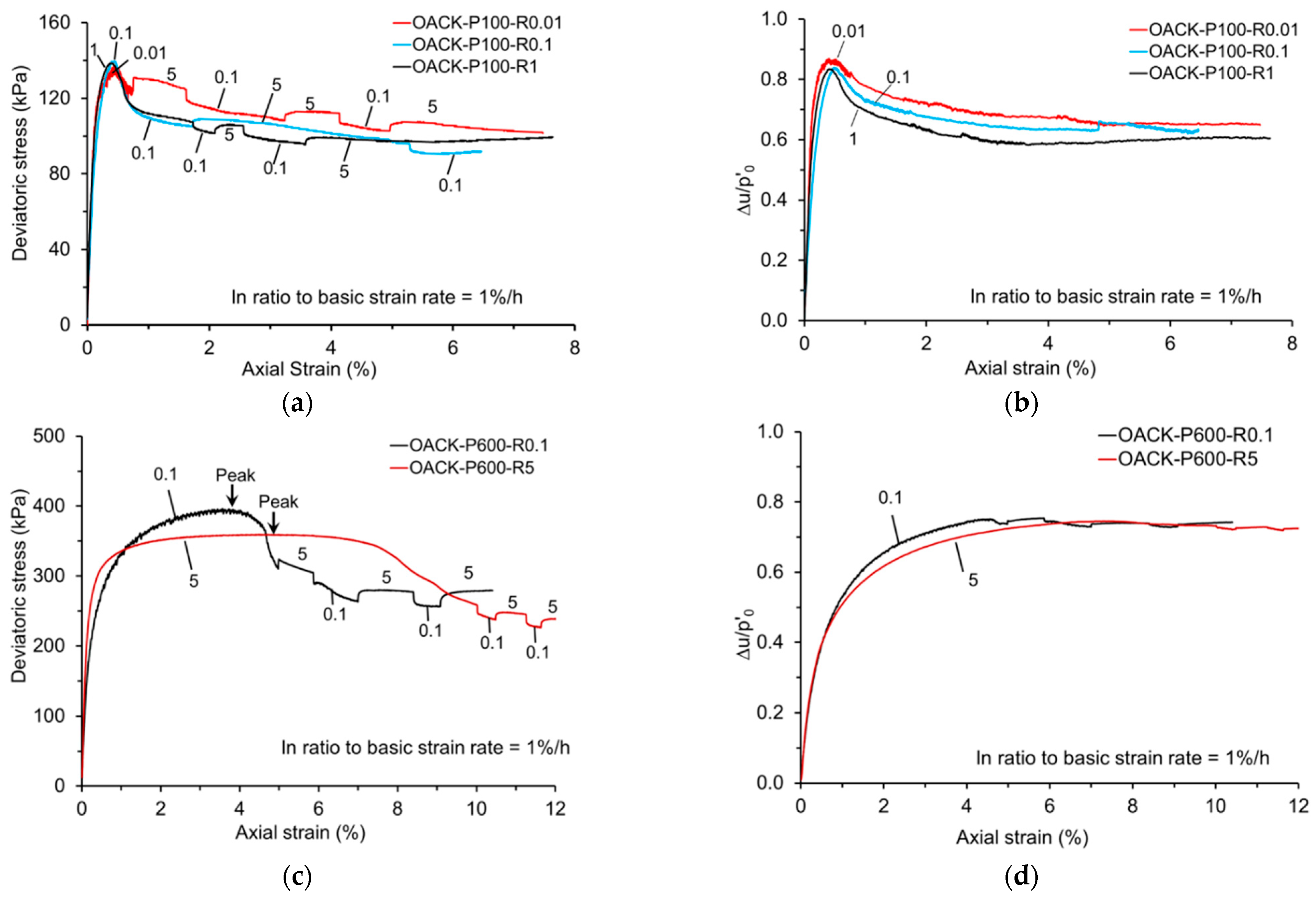
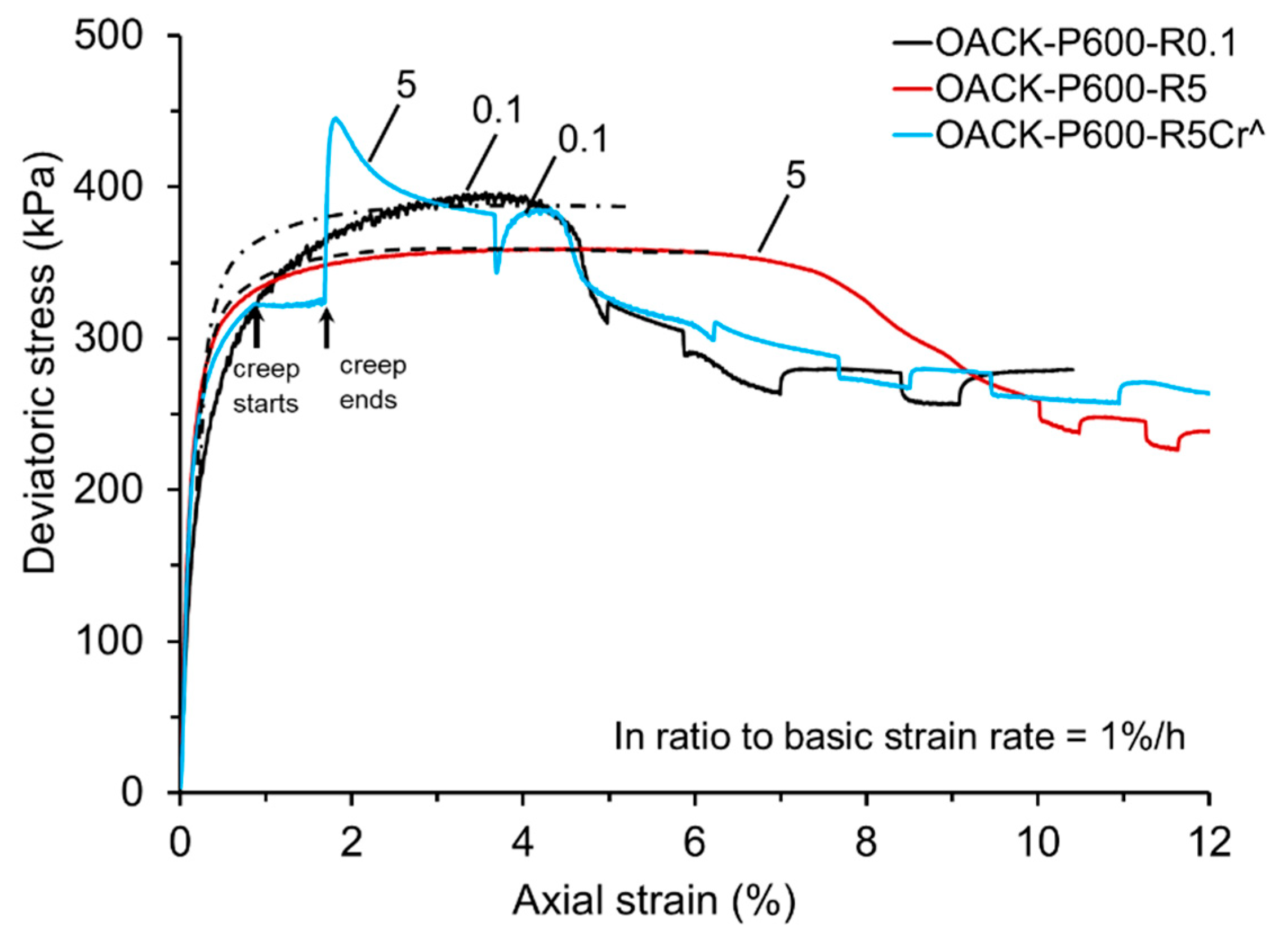
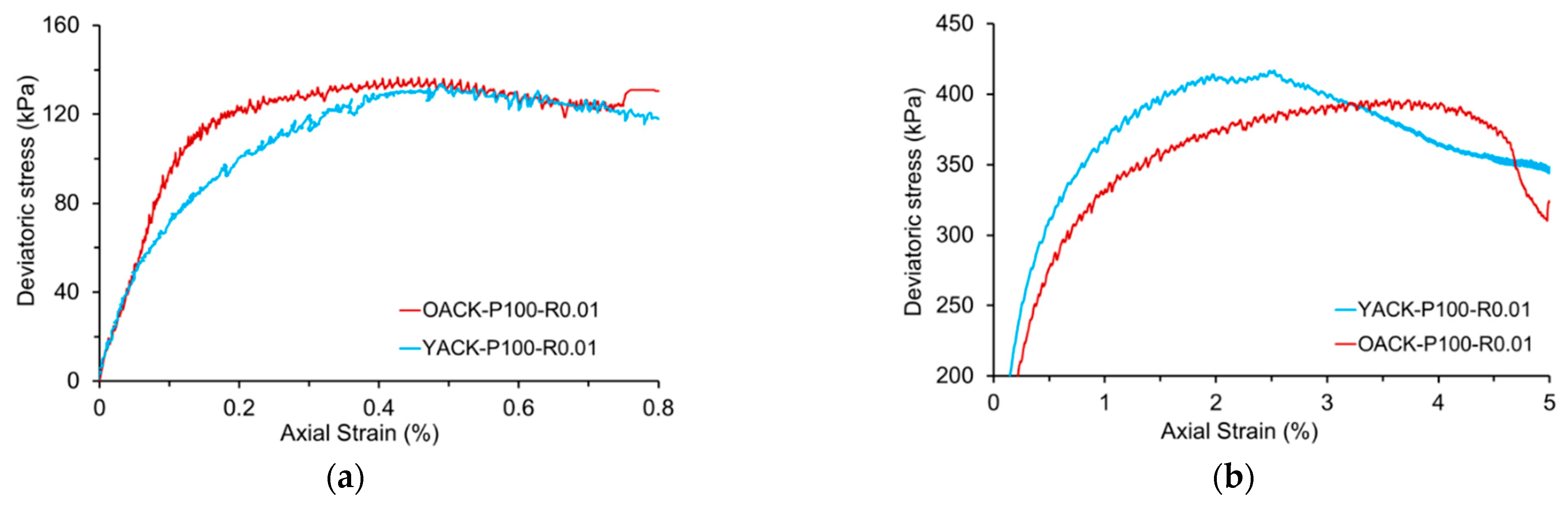
3.1. Rate Effect on Developed Structured Clay

Figure 1a shows the general stress-strain behaviour of old artificially cemented kaolin (OACK) specimens prepared with the same developed bond structures, and tested under the same low confining pressure of 100 kPa, applying different constant strain rates (0.01, 0.1, and 1%/h) during the pre-peak stage. The stress-strain behaviour exhibits a highly brittle nature, with coinciding curves up to the peak, while the excess pore pressure shows minor differences.
The rate sensitivity of the peak strength and the strain at the peak strength are insignificant. This trend is similar to the previous results for cemented kaolin conducted by Suzuki et al. [32], which suggests that 4% cement kaolin shows an insignificant effect of fast shearing on the peak and residual strength. However, this outcome deviates from the rate effect on natural cemented soils [8], where an obvious ‘positive’ rate effect on the peak strength was found. This discrepancy may arise from differences in bond composition: artificial bonds in ACK are significantly stronger than those in the base clay, whereas natural clay bonds exhibit similar strength to the base material. Consequently, the behaviour of Leda clay was predominantly influenced by the deformation of both the bonds and the base clay, whereas in ACK, the pre-peak stage behaviour was primarily governed by the bonds alone, whose strength and deformation were insensitive to the strain rate.
In order to investigate the rate effect on clay with ruptured bond structures, two specimens were tested under a higher confining stress of 600 kPa. In contrast to the response observed in pure kaolin (PK) and OACK under low confining stress, a “negative” rate effect on the peak strength was observed (Figure 1c), while the pore water pressure response shows minimal sensitivity to the strain rate (Figure 1d). This may be attributed to local drainage from the shear plane to the outside area, and the contractive behaviour results in a drier (denser) state on the shear plane. This localised drainage-induced increase in shear resistance outweighs the positive viscous effect, resulting in a “negative” rate effect. This phenomenon is further elucidated through the stress path and v-lnp’ spaces shown in Figure 2. Local drainage in non-structured PK results in a new stress path from B to F rather than the traditional path from B to E, while local drainage in the structured ACK results in a stress path from G to H to F rather than from G to I to F. The mechanics based on strain localisation and local drainage can also explain the more ‘ductile’ behaviour under high strain rates, as shown in Figure 1c.
An additional test was carried out to investigate the negative rate effect during the pre-peak stage, as shown in Figure 3. In this test, the specimen was initially subjected to a strain rate of 5%/h until the deviator stress reached approximately 90% of the peak strength. Subsequently, the test was transitioned from strain control to stress control by maintaining the deviator stress constant. This undrained creep stage lasted for nearly 40 h, which was the duration required for the specimen subjected to the slower straining of 0.1%/h to reach its peak state. Following the creep stage, a strain rate of 5%/h was resumed, and the specimen was sheared until failure.
The test performed at 5%/h with the inclusion of the creep interval reaches a higher peak strength than the test with the same strain rate without the creep stage. It is interesting to note that the peak strength achieved in the test with creep coincided with that attained in the test conducted at the slower rate of 0.1%/h. Considering that the specimens were cured for periods exceeding 28 days, it is unlikely that the 10% difference in peak strength is due to further curing. Instead, it is suggested that the duration of the test contributes as much to this apparent ageing effect, particularly when the strain rate is sufficiently low to allow for more local drainage within and outside the potential shear plane. After deceleration to the lower strain rate of 0.1%/h, the stress-strain curve is seen to rejoin the curve corresponding to that specific rate.
During the post-peak stage, the response exhibits a pronounced and persistent isotach viscous pattern, regardless of the applied confining stress (both low and high). The positive rate effect on the strength of structured clay observed in this study is in good agreement with the results of previous studies. The shear plane developed and was fully completed at approximately 1% axial strain after reaching the peak. Consequently, the dominant mechanics shift entirely towards the sliding of two relatively rigid blocks. The behaviour was more like shearing in a direct shear box, but with an inclined pre-existing shear plane. However, the pore pressure remained insensitive to the strain rate, as shown in Figure 1b,d. Therefore, the persistent stress jump observed could not be caused by a change in the excess pore water pressure. The stress jumps between the stress and strain curves with a logarithmic increase in the axial strain rate were quantified using parameter γ, where the jump in deviatoric stress, Δq, is normalised by the value at failure, qf (accounting for the initial state and confining stress level). The average rate effects show a consistent value of approximately 3%, as illustrated in Figure 4.
γ = q / q f l o g ε ˙ a f t e r / ε ˙ p r e v i o u s ,

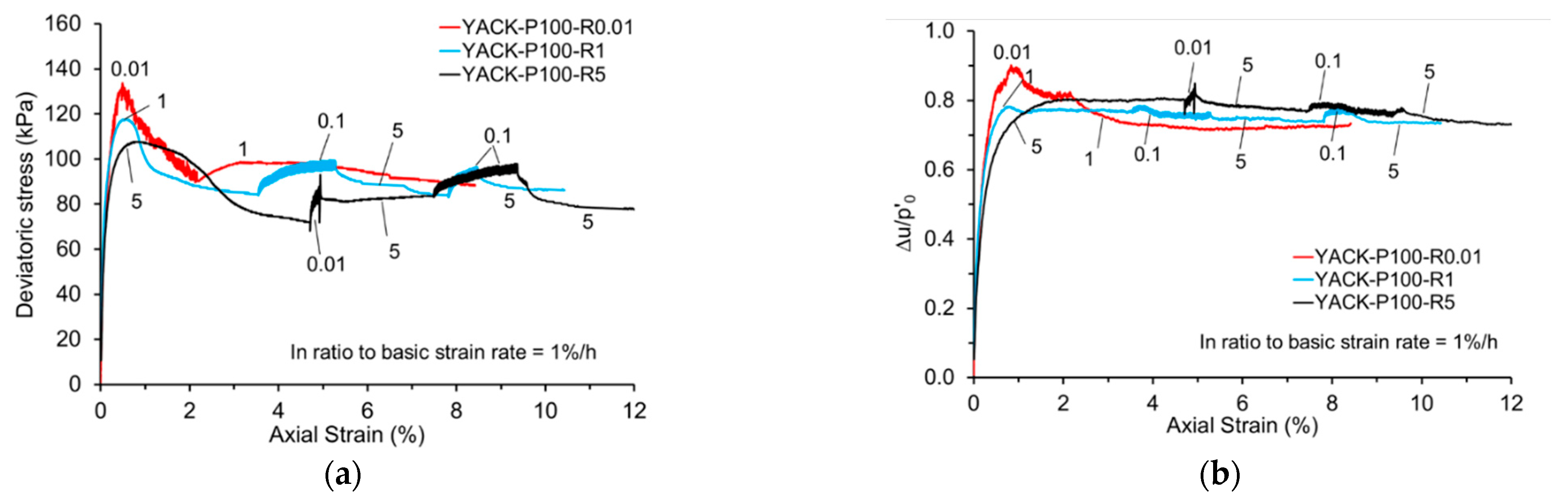
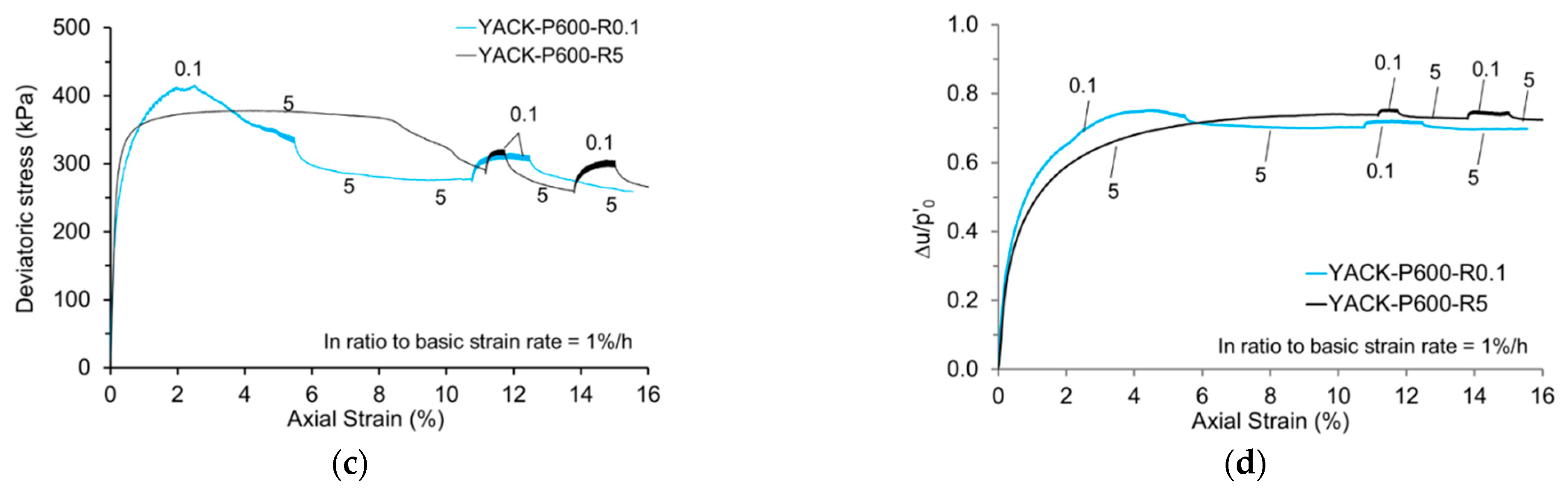
3.2. Rate Effect on Developing Structured Clay

Figure 5a shows the general stress-strain behaviour of young ACK specimens (curing for 2 days) under three different constant strain rates and a low confining stress. During the pre-peak shear stage, it is evident that slower strain rates result in higher peak strengths due to the longer curing time. Additionally, the axial strain at peak strength was slightly delayed with higher strain rates, specifically εpeak = 0.48%, 0.53%, 0.9% under 0.01%/h, 1%/h, and 5%/h, respectively. Notably, a lower strain rate resulted in a higher shear strength and more brittle behaviour, which has been found in OACK and was attributed to local drainage.
Similar results were obtained under high confining stress, as shown in Figure 5c. Comparing these results to tests conducted on OACK, it appears that the additional curing time effect due to lower strain rates is not as pronounced under such a high confining stress. Again, the volumetric change in soil dominates the behaviour of the young ACK specimen, rather than any bond structure. Furthermore, the additional strength value obtained was approximately 37.3 kPa at a slower strain rate of 0.1%/h, which closely aligns with the value observed in OACK at 37 kPa.
Figure 5b,d show the development of excess pore pressure during undrained shearing at different strain rates. In the case of OACK specimens whose structure was much stronger before peak, the pore pressure development appeared to be independent of the strain rate. Conversely, in young ACK specimens, a lower strain rate led to higher shear resistance and greater excess pore pressure. However, after reaching the peak, a relatively stable pore pressure was obtained. Furthermore, the axial strain at the peak excess pore pressure exhibits a slight delay compared to the axial strain at the peak strength.
In the post-peak shear stage, a negative rate effect was observed, accompanied by a more pronounced and regular “stick-slip” pattern [33] when the shear plane is well formed. It is important to note that the mechanism behind the negative rate effects differs significantly from that of the pre-peak shear stage: the immediate stress jump was still positive due to the rate acceleration, but it was almost overshadowed by the subsequent negative effect resulting from a combination of curing and stick-slip behaviour. Throughout the undrained shear process, the young ACK specimens continued curing and strengthening. Therefore, a slower strain rate allowed for more curing time, which led to increased shear resistance. Simultaneously, as the shear plane had already been initiated, the roughness of the surface was higher than that of the shear plane formed in OACK. This increased roughness was a consequence of clay aggregate breakage, resulting in intensified “stick-slip” behaviour associated with higher shear resistance. The rate effects were also quantified using the same method mentioned above, and the average value was around −8%, as shown in Figure 6. It is worth mentioning that since the roughness of the shear plane was determined by the entire history of post-peak shear stages, this negative rate effect was more random than the positive rate effect.

4. Discussion

According to the aforementioned test results, the strain-rate-dependent behaviour of clay, especially with bond structures, was found to be influenced by the presence and patterns of bond structures, inherent viscosity, local drainage during shear plane formation, and roughness of the shear plane. Table 2 summarises previous investigations on the effect of the rate of triaxial shearing on the strength of different types of soil with various soil structure statuses. The positive rate effect on the strength of the OACK observed in this study is in good agreement with the results of previous studies.
Since the shear behaviour was dominated by different factors during the pre-peak and post-peak shear stages, after the formation of the shear band on the specimen, it is worth comparing it with the shear behaviour under ring shear. Table 3 summarises previous studies on the rate effect of cohesive soils on residual strength. The reasons for the negative effect observed in the present study during the pre-peak stage are similar, i.e., partially/locally drained, resulting in a ‘denser’ soil status.
The Scanning Electron Microscope (S-4800, manufactured by Hitachi, Tokyo, Japan) tests have been carried out in order to investigate the microstructure of pure kaolin and cemented kaolin. The samples were collected from the shear band area of the specimens after triaxial shearing. The results indicate that the incorporation of cement leads to the formation of a flocculated and aggregated structure, which consequently results in an increase in both the pore size and particle size. Figure 7a clearly illustrates the platy nature of the kaolin particles, with their orientations being randomly distributed. Figure 7b shows the SEM images of the ACK specimens under low confining stress; the platy particles were loosely stacked with larger pores, showing lower compaction, less fragmentation, and no preferred orientation. These characteristics indicate a relatively brittle and sliding shear. In contrast, Figure 7c shows that high pressure leads to tighter particle packing, reduced porosity, increased fragmentation, and slight particle alignment along the shear direction. The shear patterns are more frictional. Additionally, the pore structures evolve from dispersed and larger pores under low pressure to compressed microcracks and sealed pores under high pressure, thereby reducing the permeability.
Furthermore, it is worth mentioning that two types of stick-slip (SS) shear patterns were observed during the entire undrained shear process, i.e., random SS during pre-peak stage for both YACK and OACK samples, and intense SS during the post-peak stage for YACK samples. Figure 8a,b show the stress-strain curves of both YACK and OACK during the pre-peak stage in undrained shearing. The ‘saw-tooth’ shape disturbance of the stress-strain curves was only present when the critical threshold strain rate associated with the confining stress was reached. For a low confining stress of 100 kPa, the critical rate was found to be as low as 0.01%/h, while for a higher confining stress of 600 kPa, the critical rate could be 0.1%/h. Additionally, the fluctuation of stresses was quite regular in OACK, whose bond structure was completely developed. The intensity of the fluctuation increased as the axial strain approached the peak. In contrast, in YACK, the fluctuations were more random, occurring both in the vertical (stress) axis and the horizontal (strain) axis. This randomness indicates the immature nature of the cementitious bonds in YACK; in other words, the bonds were simultaneously gaining strength due to curing and losing strength due to shearing, resulting in a coupling between the slow rate of shearing and the curing time effects.
Figure 9a shows the stress-strain curve of YACK during the post-peak stage of undrained shearing. According to the theory of stick-slip, under the same shear rate and roughness of the shear plane, the stick-slip effect could be manifested by the normal force on the sliding shear plane, which could be quantified by the bandwidth of the saw-tooth- shaped shear stress curve. The results indicated bandwidth values of 3.1 kPa, 4.4 kPa, 7.9 kPa, and 9.2 kPa under confining stresses 100 kPa and 600 kPa, respectively. It is observed that there exists a noticeable linear relationship between confining stress and the quantified stick-slip effect, as shown in Figure 9b.

5. Conclusions

This paper focused on the mechanism of rate effect on clayey soil with different structural states. Specifically, the artificially cemented kaolin with different curing times and confining stresses was tested at a constant strain rate at the pre-peak stage and a stepwise changed strain rate at the post-peak stage using a triaxial shear apparatus.
(1)
The fully developed ACK exhibited a shearing behaviour primarily governed by the proportion of intact bonds under low confining stresses, making it insensitive to strain rate. In contrast, under a large confining stress, the cementing bonds are significantly destroyed during isotropic compression, and a negative rate effect is observed due to local drainage at a slow rate of shearing. During the post-peak stage, the shear behaviour of the fully developed ACK switched to a pure isotach with a well-formed shear plane owing to its inherent viscosity.
(2)
The ACK with a developing structure shows a slight negative effect during the pre-peak stage under both low and high confining stresses, resulting from the combined effect of curing time and local drainage. In the post-peak stage, the presence of an intense stick-slip shear pattern and increased bond breakage at a well-formed shear plane results in an increase in shear resistance, i.e., a negative rate effect.
(3)
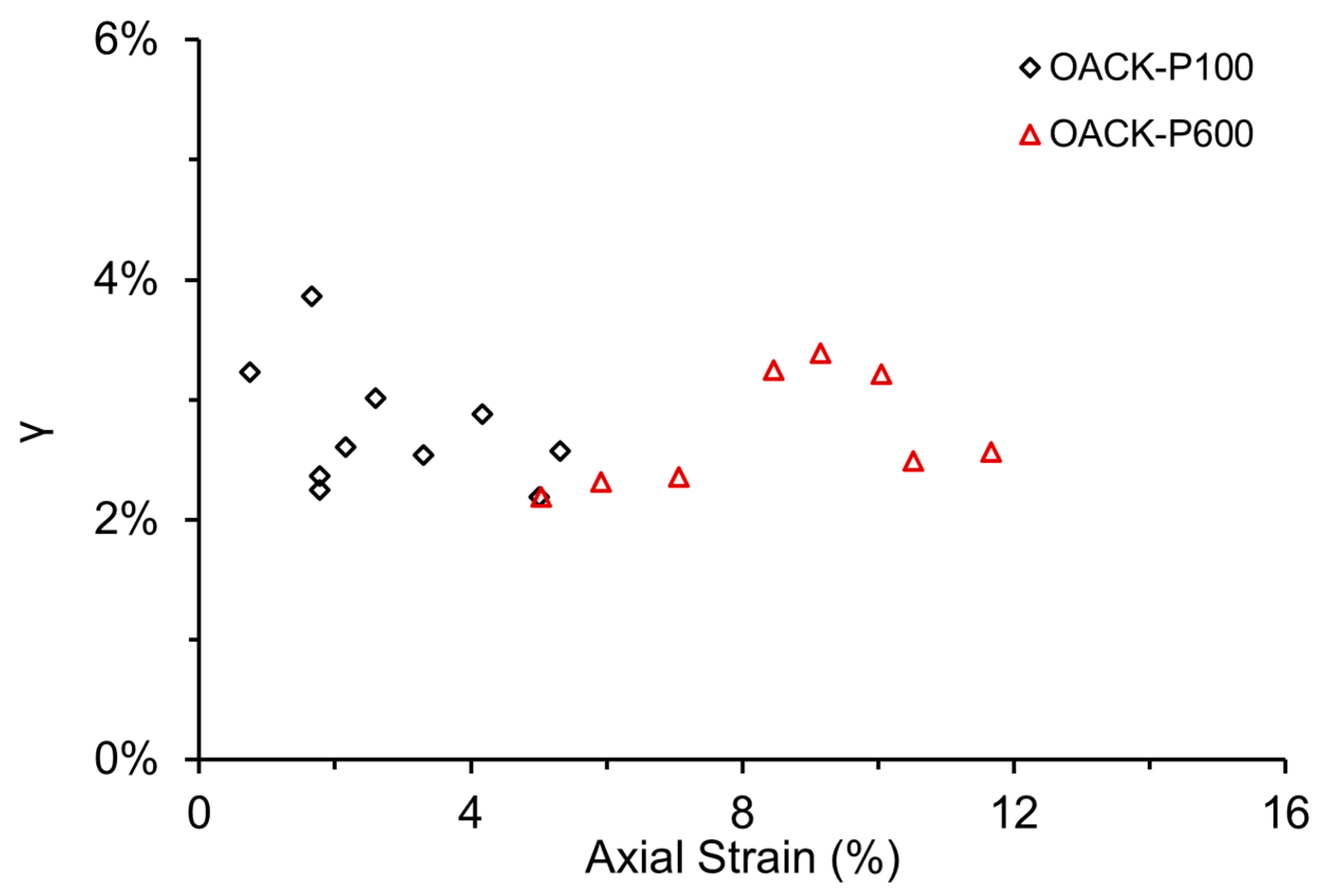
Two types of stick-slip shear patterns were observed during the undrained shearing of ACK with a developing structure. Both types of stick-slip only occurred with a critical threshold strain rate associated with the confining stress. The stick-slip effect at the post-peak stage could be manifested by the normal force on the sliding shear plane, and a linear relationship was found

Author Contributions

Conceptualisation, Q.L. and B.A.B.; methodology, Q.L. and B.A.B.; formal analysis, Q.L., X.Z. and B.A.B.; writing—original draft preparation, Q.L., X.Z. and B.A.B.; writing—review and editing, Q.L., X.Z. and B.A.B.; supervision, B.A.B.; funding acquisition, Q.L. and X.Z. All authors have read and agreed to the published version of the manuscript.

Funding

This research was funded by the National Key R&D Program of China (grant no.: 2023YFC3009300), Stable Support Plan for Colleges and Universities of Shenzhen (grant no.: 20220810151354002), and National Natural Science Foundation of China (grant no.: 52211530088, 52178375).

Institutional Review Board Statement

Not applicable.

Informed Consent Statement

Not applicable.

Data Availability Statement

The data presented in this study are available on request from the corresponding author. The data are not publicly available due to privacy.

Conflicts of Interest

No potential conflicts of interest were reported by the authors.

Abbreviations

The following abbreviations are used in this manuscript:
ACKArtificially Cemented Kaolin
YACKYoung Artificially Cemented Kaolin
OACKOld Artificially Cemented Kaolin
CRSConstant Rate of Strain
SRSStepwise change Rate of Strain
PWPPore Water Pressure
OCOvercosolidated
NCNormal Consolidated
CFClay Fraction
Recon.Reconstituted Soil
SEMScanning Electron Microscope

References

  1. Indraratna, B.; Korkitsuntornsan, W.; Nguyen, T.T. Influence of kaolin content on the cyclic loading response of railway subgrade. Transp. Geotech. 2020, 22, 100319. [Google Scholar] [CrossRef]
  2. Jiang, S.; Xu, N.; Li, Z.C. Satellite derived coastal reclamation expansion in China since the 21st century. Glob. Ecol. Conserv. 2021, 30, e01797. [Google Scholar] [CrossRef]
  3. Yapage, N.N.S.; Liyanapathirana, D.S.; Kelly, R.B. Numerical modeling of an embankment over soft ground improved with deep cement mixed columns: Case history. J. Geotech. Geoenviron. Eng. 2014, 140, 04014062. [Google Scholar] [CrossRef]
  4. Yin, J.H.; Fang, Z. Physical modeling of a footing on soft soil ground with deep cement mixed soil columns under vertical loading. Mar. Georesour. Geotec. 2010, 28, 173–188. [Google Scholar] [CrossRef]
  5. Yin, K.S.; Zhang, L.M.; Zou, H.F. Key factors for deep cement mixing construction for undredged offshore land reclamation. J. Geotech. Geoenviron. Eng. 2022, 148, 04022063. [Google Scholar] [CrossRef]
  6. Yin, Z.Y.; Zhu, Q.Y.; Zhang, D.M. Comparison of two creep degradation modeling approaches for soft structured soils. Acta Geotech. 2017, 12, 1395–1413. [Google Scholar] [CrossRef]
  7. Burland, J.B. On the compressibility and shear strength of natural clays. Géotechnique 1990, 40, 329–378. [Google Scholar] [CrossRef]
  8. Graham, J.; Crooks, J.H.A.; Bell, A.L. Time effects on the stress-strain behavior of natural soft clays. Géotechnique 1983, 33, 327–340. [Google Scholar] [CrossRef]
  9. Soga, K.; Mitchell, J.K. Rate-dependent deformation of structured natural clays. In Measuring and Modeling Time Dependent Soil Behavior; ASCE Geotechnical Special Publication: Reston, VA, USA, 1996; Volume 61. [Google Scholar]
  10. Sadeghi-Chahardeh, A.; Mollaabbasi, R.; Picard, D.; Taghavi, S.M.; Alamdari, H. Discrete Element Method Modeling for the Failure Analysis of Dry Mono-Size Coke Aggregates. Materials 2021, 14, 2174. [Google Scholar] [CrossRef]
  11. Sadeghi-Chahardeh, A.; Mollaabbasi, R.; Picard, D.; Taghavi, S.M.; Alamdari, H. Effect of Particle Size Distributions and Shapes on the Failure Behavior of Dry Coke Aggregates. Materials 2021, 14, 5558. [Google Scholar] [CrossRef]
  12. Li, P.Q.; Baudet, B.A. Strain rate dependence of the critical state line of reconstituted clays. Géotech. Lett. 2016, 6, 66–71. [Google Scholar] [CrossRef]
  13. Li, X.M.; Jia, Y.L.; Wang, Z.L. Step-changed strain rate effect on the mechanical properties of undisturbed expansive clay. Eur. J. Environ. Civ. Eng. 2024, 28, 38–52. [Google Scholar] [CrossRef]
  14. Sorensen, K.K.; Baudet, B.A.; Simpson, B. Influence of structure on the time-dependent behaviour of a stiff sedimentary clay. Géotechnique 2007, 57, 113–124. [Google Scholar] [CrossRef]
  15. Torisu, S.S.; Pereira, J.M.; De Gennaro, V. Strain-rate effects in deep marine clays from the Gulf of Guinea. Géotechnique 2012, 62, 767–775. [Google Scholar] [CrossRef]
  16. Asaoka, A.; Nakano, M.; Noda, T. Delayed compression/consolidation of natural clay due to degradation of soil structure. Soils Found. 2000, 40, 75–85. [Google Scholar] [CrossRef]
  17. Oka, F.; Kodaka, T.; Kimoto, S. Step-changed strain rate effect on the stress-strain relations of clay and a constitutive modeling. Soils Found. 2003, 43, 189–202. [Google Scholar] [CrossRef]
  18. Han, J.; Yin, Z.Y.; Dano, C. Effect of strain rate on the adhesive bond shearing resistance of stiff clay. Transp. Geotech. 2021, 27, 100479. [Google Scholar] [CrossRef]
  19. Li, Y.R.; Wen, B.P.; Aydin, A. Ring shear tests on slip zone soils of three giant landslides in the Three Gorges Project area. Eng. Geol. 2013, 154, 106–115. [Google Scholar] [CrossRef]
  20. Sassa, K.; Wang, G.; Fukuoka, H. Landslide risk evaluation and hazard zoning for rapid and long-travel landslides in urban development areas. Landslides 2004, 1, 221–235. [Google Scholar] [CrossRef]
  21. Wang, L.; Han, J.; Liu, S. Variation in shearing rate effect on residual strength of slip zone soils due to test conditions. Geotech. Geol. Eng. 2020, 38, 2773–2785. [Google Scholar] [CrossRef]
  22. Tika, T.E.; Vaughan, P.R.; Lemos, L.J.L. Fast shearing of pre-existing shear zones in soils. Géotechnique 1996, 46, 197–233. [Google Scholar] [CrossRef]
  23. Bhat, D.R. Effect of shearing rate on residual strength of kaolin clay. Electron. J. Geotech. Eng. 2013, 18, 1387–1396. [Google Scholar]
  24. Li, D.; Yin, K.; Glade, T. Effect of over-consolidation and shear rate on the residual strength of soils of silty sand in the Three Gorges Reservoir. Sci. Rep. 2017, 7, 5503. [Google Scholar] [CrossRef]
  25. Stark, T.D.; Hussain, M. Shear strength in preexisting landslides. J. Geotech. Geoenviron. Eng. 2010, 136, 957–962. [Google Scholar] [CrossRef]
  26. Gratchev, I.B.; Sassa, K. Shear strength of clay at different shear rates. J. Geotech. Geoenviron. Eng. 2015, 141, 06015002. [Google Scholar] [CrossRef]
  27. Duong, N.T.; Suzuki, M.; Van Hai, N. Rate and acceleration effects on residual strength of kaolin and kaolin–bentonite mixtures in ring shearing. Soils Found. 2018, 58, 1153–1172. [Google Scholar] [CrossRef]
  28. Delage, P. A microstructure approach to the sensitivity and compressibility of some eastern Canada sensitive clays. Géotechnique 2010, 60, 353–368. [Google Scholar] [CrossRef]
  29. Horpibulsuk, S.; Miura, N.; Nagaraj, T.S. Assessment of strength development in cement-admixed high-water content clays with Abrams’ law as a basis. Géotechnique 2003, 53, 439–444. [Google Scholar] [CrossRef]
  30. Jiang, Y.; Wang, D.; Di, S. On the compression behavior of remolded cement-admixed soft clay. Mar. Georesour. Geotec. 2017, 36, 323–330. [Google Scholar] [CrossRef]
  31. Wu, J.; Liu, S.Y.; Deng, Y.F. Microscopic phase identification of cement-stabilized clay by nanoindentation and statistical analytics. Appl. Clay Sci. 2022, 224, 106531. [Google Scholar] [CrossRef]
  32. Suzuki, M.; Hai, N.V.; Yamamoto, T. Ring shear characteristics of discontinuous plane. Soils Found. 2017, 57, 1–22. [Google Scholar] [CrossRef]
  33. Berthoud, P.; Baumberger, I. Physical analysis of the state-and rate-dependent friction law: Static friction. Phys. Rev. B 1999, 59, 14313–14327. [Google Scholar] [CrossRef]
  34. Zhu, J.G.; Yin, J.H. Strain-rate-dependent stress–strain behavior of overconsolidated Hong Kong marine clay. Can. Geotech. J. 2000, 37, 1272–1282. [Google Scholar] [CrossRef]
  35. Cheng, C.M.; Yin, J.H. Strain-Rate Dependent Stress-Strain Behavior of Undisturbed Hong Kong Marine Deposits under Oedometric and Triaxial Stress States. Mar. Georesour. Geot. 2005, 23, 61–92. [Google Scholar] [CrossRef]
  36. Scaringi, G.; Di Maio, C. Influence of displacement rate on residual shear strength of clays. Procedia Earth Planet. Sci. 2016, 16, 137–145. [Google Scholar] [CrossRef]
Figure 1. Test results on OACK at low and high confining stress: (a,c) deviatoric stress versus axial strain; (b,d) normalised pore pressure response.
Applsci 15 05839 g001
Figure 2. Illustration of local drainage and its ‘negative rate effect’ during undrained shear on OACK: (a) stress space; (b) water content and effective confining stress space.
Applsci 15 05839 g002
Figure 3. Additional Creep test of OACK at pre-peak shearing stage. ^ means test with creep stage.
Applsci 15 05839 g003
Figure 4. Positive rate effect of OACK during the post-peak shearing stage.
Applsci 15 05839 g004
Figure 5. Test results on YACK at low and high confining stresses: (a,c) deviatoric stress versus axial strain; (b,d) normalised pore pressure response.
Applsci 15 05839 g005aApplsci 15 05839 g005b
Figure 6. Negative rate effect of YACK during post-peak shearing stage.
Applsci 15 05839 g006
Figure 7. SEM images of the shearing specimens: (a) pure kaolin after shearing; (b) cemented kaolin after shearing at a low confining stress of 100 kPa; (c) cemented kaolin after shearing at a high confining stress of 600 kPa.
Applsci 15 05839 g007
Figure 8. Stick-slip shear pattern observed in the pre-peak shearing stage of both YACK and OACK: (a) shearing at a low confining stress of 100 kPa; (b) shearing at a high confining stress of 600 kPa.
Applsci 15 05839 g008
Figure 9. Stick-slip shear pattern observed in the post-peak shearing stage of YACK: (a) under different confining stresses (50, 100, 300, and 600 kPa) and (b) Quantified stick-slip effect.
Applsci 15 05839 g009
Table 1. Summary of triaxial tests on ACK specimens.
Test
Name
Curing &
Consolidation
Stress (kPa)
Curing Time (Days)p’0Pre-Peak
Strain Rate (%/h)
Post-Peak
Strain Rate (%/h)
OACK-P100-R0.01100301000.010.1/5
OACK-P100-R0.10.10.1/5
OACK-P100-R110.1/5
OACK-P600-R0.16000.10.1/5
OACK-P600-R550.1/5
OACK-P600-R5Cr ^5 + creep0.1/5
YACK-P100-R0.0110021000.010.1/5
YACK-P100-R110.1/5
YACK-P100-R550.1/5
YACK-P600-R0.16000.10.1/5
YACK-P600-R550.1/5
Notes: OACK means Old ACK cured for 30 days, YACK means Young ACK cured for 2 days; P100 means the confining stress equal to 100 kPa; R0.01 means the strain rate is 0.01%/h during the pre-peak shearing stage. ^ Test with undrained creep shear during pre-peak stage.
Table 2. Rate effect of clayey soils under triaxial shearing.
Type of SoilSoil Structure StatusShearing ProcedureShear Rate
(%/h)
Rate EffectMechanismReference
Pre-Peak/Small StrainPost-Peak /Large Strain
Belfast clayOC UndisturbedTriaxial
SRS
0.05-0.5-5PositivePositiveShear viscosityGraham et al. [8]
Hong Kong Marine clayNC + OC Recon.Triaxial
CRS
0.15-1.5-15PositivePositiveShear viscosityZhu & Yin [34]
OC UndisturbedTriaxial
SRS
0.2-2-20PositivePositiveShear viscosity and smaller excess PWP at a higher rateCheng & Yin [35]
London clayNC + OC Recon.Triaxial
SRS
0.007-0.05-0.5PositiveInsensitiveShear viscosity and decaying isotach at large strainSorensen et al. [14]
OC UndisturbedTriaxial
SRS
0.05-0.2-0.8PositivePositiveRate dependence of post-sedimentation structure
Merville stiff clayNC + OC Recon.Triaxial
CRS
0.26-2.6-26.0PositivePositiveShear viscosityHan et al. [18]
OC UndisturbedTriaxial
CRS
0.26-2.6-26.0PositiveInsensitiveRate dependence of interparticle debonding
Pure Kaolin clayNC + OC Recon.Triaxial
SRS
0.1-0.5-2-10PositivePositiveShear viscosityLi & Baudet [12]
Artificial cemented Kaolin clayOACK at low p’Triaxial
CRS + SRS
0.01-0.1-1-5InsensitivePositiveStiff bonds at pre-peak; shear mode change at post-peakThis study
OACK at high p’Triaxial
CRS + SRS
0.1-5NegativePositiveBonds broken and local drainage near shear plane;
YACK at low p’Triaxial
CRS + SRS
0.01-1-5NegativeNegativeCombined curing effect and stick-slip
YACK at high p’Triaxial
CRS + SRS
0.1-5NegativeNegativeCombined curing effect and stick-slip
OC—Overconsolidated; NC—Normal Consolidated; CRS—Constant Rate of Strain; SRS—Stepwise change Rate of Strain; PWP—Pore Water Pressure.
Table 3. Rate effect of 11 clayey soils under ring shearing.
Type of SoilSoil Structure StatusShearing ProcedureShear Rate (mm/min)Rate Effect on
Residual Strength
MechanismReference
Kaolin clayRecon.
CF = 74%
Ring shear0.013-0.13-1.12-9.9-90.8-230PositiveShear viscosity; sliding to turbulent shear with a higher rateTika et al. [22]
ClaystoneRecon.
CF = 52%
Ring shear0.05-0.92-10-100-400-6000NegativeSoils with transitional shear
Amber clayRecon.
CF = 66%
Ring shear12-60-120-300NegativeHealing, broken bonds restoration at a lower rateGratchev & Sassa [26]
Brown clayRecon.
CF = 19%
Ring shear12-60-120-300NegativeHealing, broken bonds restoration at a lower rate
Kaolin clayRecon.
CF = 100%
Direct shear3.6-36-360NegativeLarger excess PWP with a higher rateLi et al. [19]
Kaolin clayRecon.
CF = 74%
Ring shear0.09-0.6-1-11.1PositiveShear viscosity; Only significant v > 0.5 mm/minScaringi & Di Maio [36]
Kualiangzi landslideRecon.
CF = 74%
Ring shear0.002-0.6-1-120PositiveShear viscosity; only positive v > 3 mm/min
Kaolin clayRecon.
CF = 74%
Ring shear0.02-0.1-0.2-1-10PositiveShear viscosity; Only significant v > 0.1 mm/minSuzuki et al. [32]
4% Cemented Kaolin clayRecon.Ring shear0.02-0.1-0.2-1-10Insensitiveundulating shear behaviour
Kaolin clayRecon.
CF = 46%
Ring shear0.02-0.2-2-20PositiveShear viscosity; sliding to turbulent shear;Duong et al. [27]
Kaolin + Bentonite clayRecon.
CF = 50.8%
Ring shear0.02-0.2-2-20NegativeLarger excess PWP and finer particles at the shear zone with a higher rate
Recon.—Reconstituted Soil; CF—Clay Fraction; PWP—Pore Water Pressure.
Disclaimer/Publisher’s Note: The statements, opinions and data contained in all publications are solely those of the individual author(s) and contributor(s) and not of MDPI and/or the editor(s). MDPI and/or the editor(s) disclaim responsibility for any injury to people or property resulting from any ideas, methods, instructions or products referred to in the content.

