1. Introduction
The accurate detection and mapping of subsurface utilities are essential for ensuring safety and operational efficiency in excavation and construction projects. This is especially important in urban areas where underground infrastructure is highly dense and often undocumented. Failure to identify subsurface utilities can result in serious accidents, economic losses, and project delays. A notable example is the 2003 Daegu subway fire disaster in South Korea, which led to over 100 fatalities and widespread damage, emphasizing the importance of reliable underground utility detection [
1,
2,
3,
4].
To address such risks, non-destructive geophysical methods have been widely adopted, with Ground-Penetrating Radar (GPR) being one of the most commonly used techniques. GPR operates by emitting high-frequency electromagnetic waves and analyzing their reflections from subsurface features with differing dielectric properties [
5,
6]. While GPR is capable of detecting both metallic and non-metallic utilities under favorable conditions, its performance is highly affected by soil conductivity, water content, and material type. Ground-Penetrating Radar (GPR) has been widely used for subsurface detection; however, its effectiveness diminishes in complex soil conditions, such as heterogeneous compositions or high moisture content. Ref. [
7] reviewed the application of GPR in agricultural settings and noted challenges in accurately sensing subsurface features under such conditions. Furthermore, ref. [
8] highlighted the limitations of electromagnetic methods like GPR, particularly in detecting non-metallic pipelines such as PVC or PE, and emphasized the potential of acoustic-based techniques as alternative solutions. Ref. [
9] proposed an improved GPR data processing approach tailored to subsurface utility detection in urban environments, demonstrating a higher detection accuracy even under complex underground conditions.
To overcome these constraints, the All Materials Locator (AML) has emerged as a promising alternative. Unlike GPR, AML integrates ultra-high-frequency electromagnetic sensing and acoustic/ultrasonic detection to identify subsurface anomalies based on variations in material density and structure. This hybrid approach makes AML less dependent on the electromagnetic properties of surrounding soils, allowing for more consistent detection of both metallic and non-metallic utilities. Preliminary studies suggest that AML offers greater depth penetration and an improved accuracy across diverse soil conditions [
10,
11].
Recent developments in subsurface utility detection have also emphasized the effectiveness of hybrid systems that combine electromagnetic and acoustic sensing approaches, demonstrating an improved performance under variable soil and infrastructure conditions [
12].
However, AML systems may still be influenced by environmental variability, operator technique, and site-specific conditions such as soil heterogeneity—factors that necessitate systematic field validation.
This study aims to systematically evaluate the performance of the AML system using a nationally certified underground utility test site operated by Sungkyunkwan University. By employing standardized testbeds with both metallic and non-metallic pipelines buried at depths up to 3 m, the study goes beyond manufacturer-driven validations to provide field-based evidence of AML’s detection accuracy under regulatory conditions. The findings highlight the system’s potential as a reliable alternative to conventional GPR, particularly in detecting deeply buried non-metallic utilities—an area where traditional technologies often fall short.
2. Materials and Methods
2.1. Ground-Penetrating Radar
Ground-Penetrating Radar (GPR) is a non-destructive geophysical method that emits high-frequency electromagnetic (EM) waves to generate images of subsurface structures and buried utilities [
5]. The effectiveness of GPR is based on variations in the physical and electrical properties of subsurface materials, which influence the propagation and reflection of EM waves [
13].
GPR typically operates within a frequency range of 10 MHz to 1000 MHz. Higher frequencies provide finer resolution but limited penetration depth, while lower frequencies penetrate deeper but offer lower resolution [
9]. When EM waves encounter interfaces between materials with different dielectric constants, a portion of the wave is reflected back to the receiver, and the remainder continues to travel deeper into the subsurface [
5,
6].
The strength of these reflections and the velocity of wave propagation are governed by the dielectric contrast between the layers. By analyzing the time delay of the returned signals, it becomes possible to estimate the depth, thickness, and geometry of features such as layers, fractures, and voids [
9,
12]. This capability makes GPR a widely applied tool for detecting both metallic and non-metallic objects embedded in materials such as soil, rock, and concrete [
12].
As illustrated in
Figure 1, when EM waves encounter boundaries between materials with differing dielectric properties, the reflected signals generate a time delay profile. These profiles can then be processed to produce detailed cross-sectional images of subsurface structures [
14].
The reflection strength and wave velocity are governed by the contrast in dielectric properties, and by measuring the time delay of returned signals, it is possible to estimate the depth, thickness, and spatial distribution of subsurface features such as layers, fractures, and voids. This makes GPR a widely used non-destructive method for locating both metallic and non-metallic objects buried within soil, rock, or other opaque media [
15,
16,
17,
18,
19,
20,
21,
22]. As illustrated in
Figure 1, when electromagnetic waves encounter interfaces between materials with different dielectric properties, a portion of the signal is reflected back to the receiver while the remainder continues to propagate through the medium. This interaction generates a time delay profile that enables the visualization of subsurface structures, as described by [
14].
Recent developments have focused on improving the detection of buried non-metallic pipelines using advanced signal processing and hybrid sensing methods. For instance, ref. [
23] proposed a GPR-based technique specifically tailored for fiber-reinforced polymer (FRP) and non-metallic pipe detection. Ref. [
8] offered a comprehensive review of acoustic-based methods, highlighting their integration potential with GPR systems. Refs. [
24,
25] introduced wavelet cross-correlation and acoustic attenuation models for localizing polyethylene (PE) pipelines, demonstrating an enhanced accuracy under complex subsurface conditions. Furthermore, ref. [
26] applied an elliptical inversion model to estimate pipe direction and curvature from GPR imagery, representing a novel approach to the spatial interpretation of buried infrastructure.
2.2. GPR Performance Under Identical Site Conditions
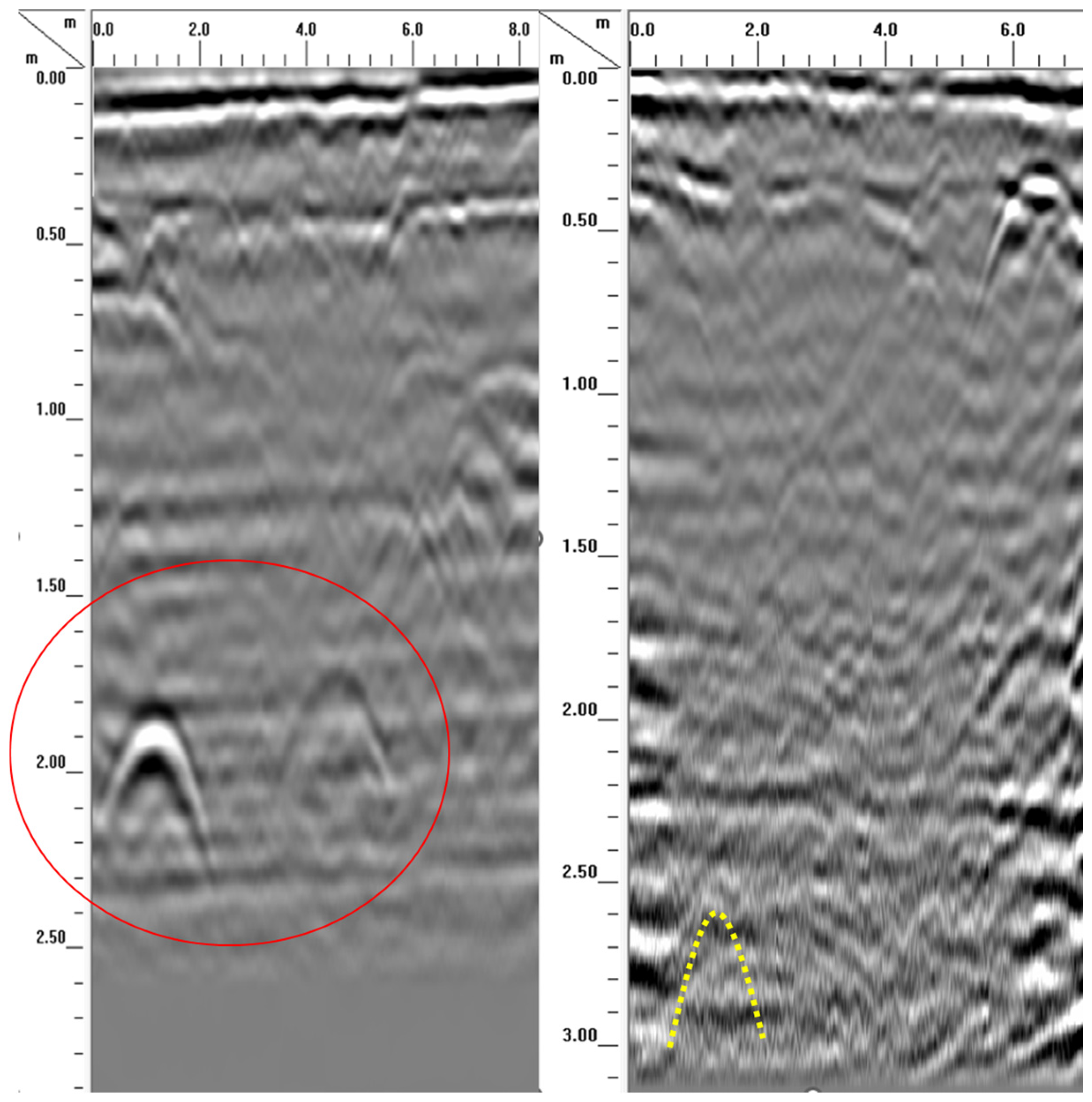
To enable a direct performance comparison with the AML system, Ground-Penetrating Radar (GPR) tests were conducted at the same certified underground utility test site, under identical environmental and operational conditions. Two representative GPR B-scan images were selected to demonstrate the detection capabilities at different burial depths of non-metallic pipelines.
As shown in the left panel of
Figure 2, a pipeline buried at a depth of 2.0 m produced a distinct hyperbolic reflection pattern, highlighted by a red circle. This reflection indicates successful detection of the buried target and confirms that GPR is capable of identifying subsurface utilities at moderate depths under favorable soil conditions. However, the signal clarity rapidly degrades beyond the 2.0 m mark, with a diminished reflection amplitude and increased noise, suggesting a reduction in effective penetration depth.
In contrast, the right panel of
Figure 2 illustrates a GPR scan of the same site where a polyethylene (PE) pipeline is known to be buried at a depth of 3.0 m. The area corresponding to the expected pipe location is marked with a yellow dashed box. Despite multiple scans, varying antenna frequencies, and signal processing enhancements, no discernible reflection pattern was observed at or near the 3.0 m depth. The loss of coherence and absence of hyperbolic signatures in this zone indicates that the GPR system was unable to detect the deeply buried non-metallic target under the given soil conditions.
These results empirically support previous studies reporting the limitations of GPR in detecting deep, non-metallic utilities [
9,
13]. The primary contributing factors include signal attenuation in decomposed granite soil and the low dielectric contrast between PE materials and their surrounding medium. Such conditions result in weak or undetectable reflections, particularly at depths beyond 2.5 m.
In comparison, the AML system, tested under the same conditions, successfully detected the same 3.0 m deep PE pipeline with high accuracy and consistency across 32 trials, as described in
Section 3.1. This performance contrast demonstrates AML’s superior capability for deeper and more reliable detection of non-metallic subsurface utilities, especially in scenarios where traditional GPR techniques are prone to failure.
2.3. AML System
The All Materials Locator (AML) is a handheld subsurface utility detection device that utilizes modulated ultra-high radio frequencies (UHRF) to detect variations in subsurface density. This technology is particularly effective in identifying underground structures by analyzing contrasts in material composition and density, making it well suited for detecting linear features such as pipelines, cables, and other buried infrastructure [
27].
According to the manufacturer, the AML Pro™, SubSurface Instruments, Inc. (De Pere, WI, USA) employs ultra-high radio frequency technology to locate buried PVC and other plastic pipes using GPS and advanced patented digital signal processing. Additionally, the AML Pro™ is capable of detecting subsurface materials of various compositions—plastic, metal, wood, cable, or pipe—and functions effectively under challenging field conditions, including clay, wet soil, snow, and even standing water [
27,
28,
29].
These capabilities and application ranges of the AML device are consistently documented in the manufacturer’s specifications and product manuals, as well as in third-party technical reports that assess its performance under various field conditions [
27,
28,
29].
One major advantage of ultrasonic-based detection systems like the AML is that they do not require direct physical contact with the target. Instead, they rely on wave propagation and reflection to detect and localize subsurface objects. Unlike traditional electromagnetic or Ground-Penetrating Radar (GPR) systems, ultrasonic-based methods are less sensitive to the electromagnetic properties of surrounding materials, allowing for greater adaptability across varying soil types and moisture conditions [
30,
31].
The detection process of the All Materials Locator (AML) begins when the device emits high-frequency acoustic- or radio-frequency waves into the ground. These waves propagate through multiple subsurface layers and interact with embedded materials or voids that differ in density. When such discontinuities are encountered, a portion of the wave energy is reflected, while the remaining energy continues to propagate deeper. The reflected signals are received and analyzed to calculate the time delay between emission and reception, which is subsequently used to determine the depth and location of buried objects. The acquired data are then processed using computational algorithms to generate visual representations of the subsurface structure [
11,
23].
The fundamental principle of this method—based on time-of-flight measurement and reflection of wave energy—has been widely adopted in recent ultrasonic detection research. For instance, ref. [
32] developed a positioning algorithm for buried polyethylene pipelines by considering acoustic attenuation properties in heterogeneous soil environments. Similarly, ref. [
33] proposed an ultrasonic array tomography approach to accurately reconstruct subsurface images and detect cracks within reinforced concrete structures. Ref. [
34] demonstrated that real-time signal processing techniques embedded in ultrasonic visualization frameworks can significantly improve defect localization accuracy. In another study, ref. [
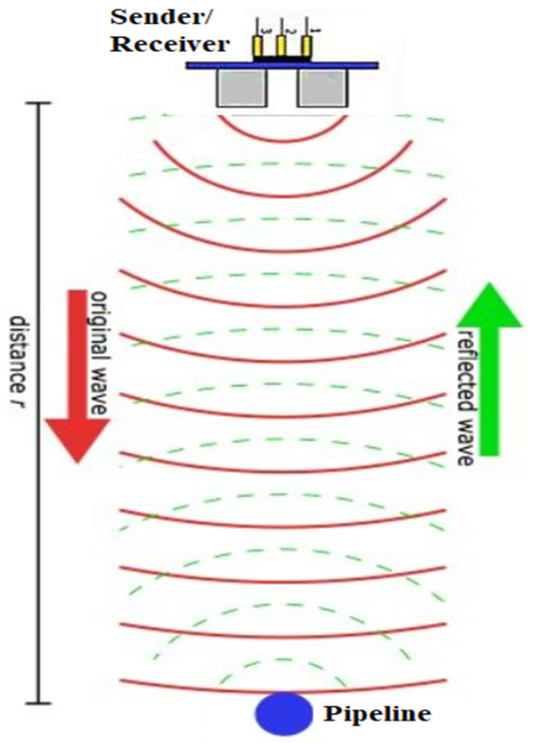
35] numerically compared physics-based and machine learning approaches applied to Ground-Penetrating Radar (GPR) data for underground utility network characterization. Their results confirmed the effectiveness of signal interpretation methods, particularly travel time analysis, for determining the depth and geometry of buried infrastructure. These findings are consistent with the operational principles of All Materials Locator (AML) devices and further support their applicability in various geotechnical and infrastructure monitoring contexts. As illustrated in
Figure 3, the fundamental principle of this method relies on the time-of-flight of transmitted and reflected waves, a concept similar to that used in ultrasonic detection and widely applied in recent subsurface sensing studies.
The All Materials Locator (AML) is a handheld utility detection device that operates based on ultra-high radio frequency (UHRF) sensing technology. Rather than relying on conductivity or acoustic propagation, the AML system detects subsurface objects by identifying differences in material density through modulated UHRF signals. These signals interact with buried structures that present dielectric contrasts, and the reflected signals are analyzed using proprietary digital signal processing algorithms to determine the location and depth of the target.
While the AML system operates using ultra-high radio frequency (UHRF) sensing and not acoustic wave propagation, insights from previous ultrasonic detection studies are useful for understanding the broader challenges and principles of non-contact subsurface sensing. For instance, ref. [
36] demonstrated that pulse–echo ultrasonic monitoring could evaluate sediment buildup along the interior walls of PVC pipelines with less than 2.5% error. Similarly, ref. [
37] proposed a machine learning-based ultrasonic-guided wave technique to detect subsurface cracks in polyethylene pipes. Although these studies involve fundamentally different detection mechanisms, they illustrate the importance of density-related sensing in locating non-metallic underground utilities without requiring direct access.
Ultrasonic-based detection systems have long been studied in the field of non-destructive testing (NDT). These systems offer high-resolution measurements and are capable of identifying structural anomalies in non-metallic infrastructure, such as PVC, PE, and fiber-optic cables [
38,
39]. However, they also face notable limitations, including a reduced penetration depth in moist or heterogeneous soils and susceptibility to wave scattering, which can result in false positives or inaccurate localization [
40,
41,
42].
These challenges underscore the advantage of UHRF-based devices like AML, which are not constrained by the acoustic properties of the surrounding medium. By relying on the electromagnetic density contrast rather than the wave velocity or attenuation, AML provides a robust alternative for detecting deeply buried non-metallic utilities, especially under complex soil conditions where acoustic methods struggle.
Similar operational considerations for acoustic detection devices have been addressed in recent field-based evaluations, which emphasize the role of user technique and environmental variables in determining measurement accuracy [
43]. A representative example of this process is illustrated in
Figure 4, which demonstrates a step-by-step method for estimating pipe depth using the AML device at a 45° angle (SubSurface Instruments, 2024 [
27]).
2.4. Establishment of the Performance Test Site
Since 2010, the Sungkyunkwan University Geospatial Technology Center has operated a certified test site dedicated to the evaluation of underground utility detection systems. The facility serves as a standardized environment for validating the depth range, positional accuracy, and detection reliability of various sensing technologies. The 25 m × 25 m testbed is systematically organized into two zones: one comprising metallic conduits and the other composed of non-metallic lines such as PVC and PE pipelines.
Although no globally standardized depth is universally enforced, underground utilities are typically installed at approximately 3 m. To simulate a range of real-world field conditions, additional test lines were installed at a depth of 2 m for research and calibration purposes. The conduits were constructed in accordance with national specifications regarding diameter, wall thickness, and material classification.
The backfill consisted of a 30 cm thick layer of compacted decomposed granite soil, selected for its favorable wave transmission characteristics. This layer was then covered with 5 cm of asphalt to replicate typical urban pavement conditions. To ensure accurate spatial referencing, a total station was used to measure and record the three-dimensional coordinates of each buried conduit. The resulting dataset enables the precise assessment of detection accuracy, allowing for consistent comparisons between different types of utility detection equipment.
In addition, the testbed includes features such as conductive tracer wires along metallic pipelines and high-contrast positioning for non-metallic lines. These components enhance the reproducibility and repeatability of detection scenarios, providing a standardized environment for validating the performance of GPR, AML, and other smart locator technologies.
According to [
44] well-defined test environments are essential for evaluating the positional accuracy and detection reliability of underground utility sensing systems using GPR and similar technologies. Similarly, ref. [
45] emphasized the importance of structured testing environments in assessing the performance of underground utility detection equipment. Furthermore, ref. [
46] highlighted that integrating AR and GIS technologies can significantly enhance the visualization and mapping of underground utilities, facilitating real-time data sharing and improving communication among stakeholders. The testbed was constructed with various underground utilities, including metallic and non-metallic pipes, as shown in
Figure 5.
To ensure procedural consistency across the two-year testing period, all 32 AML measurements were conducted by the same operator under dry environmental conditions, with no rainfall occurring for at least three days prior to each trial. Pre-calibration of the AML device was performed before each measurement session, and no drift or recalibration adjustments were necessary throughout the experimental timeline. This methodological consistency helped mitigate operator-induced variability and environmental influences, thereby enhancing the reliability and reproducibility of the recorded results.
2.5. Testing of Various Instruments
We tested the performance of both GPR and AML systems at the certified underground utility detection test site operated by Sungkyunkwan University. This site provides a standardized environment for evaluating whether detection systems comply with South Korea’s regulatory standards, including minimum detection depth, horizontal and vertical accuracy, and object classification capability.
GPR (Ground-Penetrating Radar) is a non-destructive testing method that transmits high-frequency electromagnetic waves through the ground using transmitting and receiving antennas. These waves interact with subsurface structures, allowing for the detection of buried objects based on signal reflection and time delay. GPR has been widely adopted for applications such as utility mapping, tunnel inspection, and structural health monitoring due to its rapid data acquisition, high precision, ease of deployment, and cost efficiency [
9,
13].
The Sungkyunkwan University Geospatial Technology Center has operated its certified performance evaluation site since 2010. The 25 m by 25 m testbed is divided into two dedicated zones: one for metallic conduits and another for non-metallic conduits, including PVC and PE pipes. This configuration enables comprehensive testing under realistic underground conditions [
13].
In accordance with national standards, the standard depth for conduit installation is 3 m. To simulate varying site conditions, additional conduits have been installed at a depth of 2 m. All pipelines were constructed in compliance with legal specifications, including pipe diameter, wall thickness, and material type. The backfill material consists of a 30 cm layer of compacted decomposed granite soil, known for its favorable electromagnetic and acoustic transmission characteristics. A 5 cm asphalt overlay simulates urban pavement environments.
To ensure the accurate spatial positioning of test targets, a total station was used to record the horizontal and vertical coordinates of each conduit, generating a 3D reference model. This allows for reliable comparison between the different types of detection equipment and facilitates precise accuracy evaluation.
Figure 6 presents the experimental flowchart for subsurface utility detection using AML measurements and subsequent data analysis.
3. Results
3.1. Summary of Field Test Results
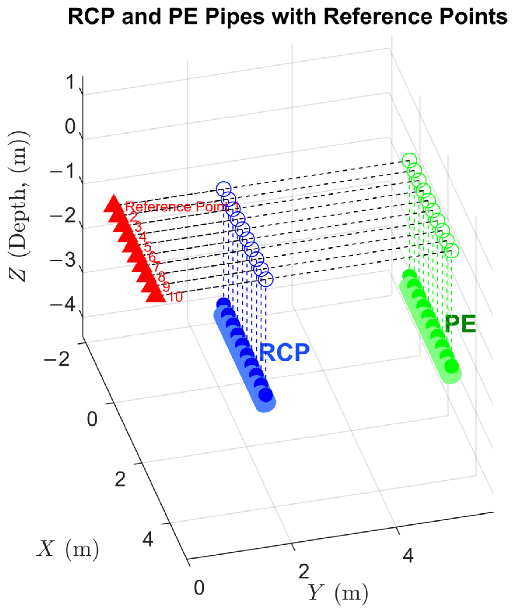
Field evaluations of the All Materials Locator (AML) system were conducted at a certified underground utility testbed designed to simulate standardized detection conditions. The facility includes both metallic and non-metallic pipelines, notably Reinforced Concrete Pipes (RCP) and polyethylene (PE) pipes, installed horizontally at controlled depths of 2 m and 3 m.
This study focuses on the 3 m deep non-metallic targets. To evaluate detection accuracy, each pipeline was conceptually divided into 10 equal segments along its longitudinal axis. The vertical depth of each corresponding surface point, as well as its horizontal distance from a reference point (placed above ground), was recorded. The geometric layout of the subsurface pipelines and the vertical projection of measurement points onto the surface are visualized in
Figure 7. This illustration helps clarify the spatial relationships between the pipelines and the surface reference points used during testing.
Table 1 presents the measured results for both RCP and PE pipelines buried at 3 m depth. Each row shows the horizontal surface position and vertical depth of each target segment, along with the horizontal distance between the surface point and the reference point above ground.
The AML system demonstrated consistent detection capabilities under these controlled conditions. All 10 points on each pipeline were successfully detected. The average depth of the detected signals for RCP and PE pipelines was approximately 2.630 m and 2.524 m, respectively, with minimal variation across repeated measurements. The horizontal distance from the reference point averaged approximately 2.18 m for RCP and 5.75 m for PE pipelines. These results confirm the device’s ability to detect non-metallic utilities with high positional accuracy and repeatability in favorable soil conditions.
3.2. Quantitative Assessment of AML Accuracy in Meeting Korean Depth and Positioning Regulations
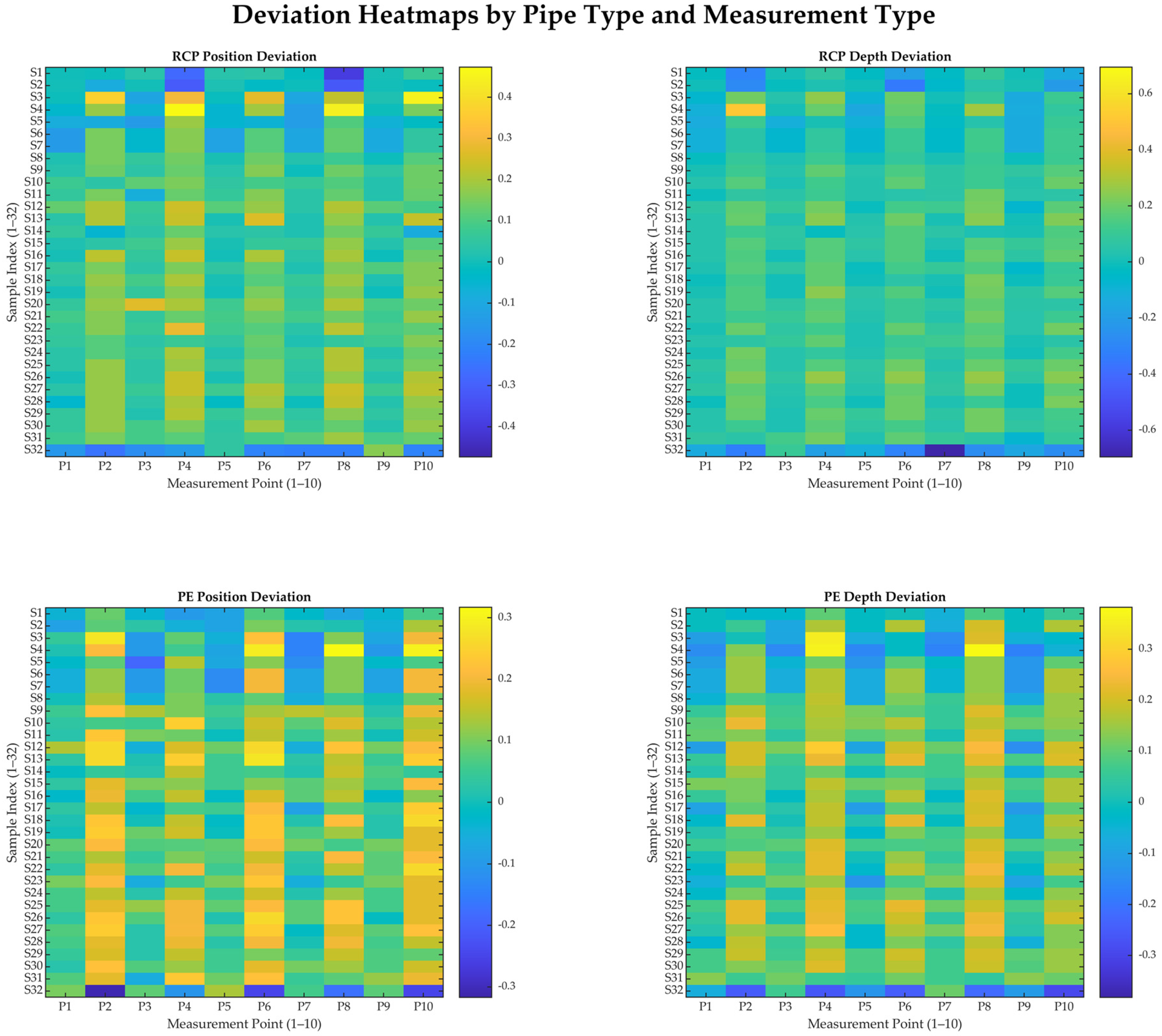
In South Korea, the regulatory standards for underground utility detection require a minimum detection depth of 3 m and mandate that both horizontal (position) and vertical (depth) deviations remain within ±0.30 m for metallic and non-metallic pipelines. To assess the compliance of the All Materials Locator (AML) system with these standards, field observations were collected across 32 samples, each containing 10 measurement points for both RCP (Reinforced Concrete Pipe) and PE (polyethylene) conduits.
The deviation values were derived by subtracting the standard reference values presented in
Table 1 (see
Section 3.1) from the actual measured values. Each measurement yielded four types of deviation values per point: ΔRCP Position, ΔRCP Depth, ΔPE Position, and ΔPE Depth. These were then aggregated across all 10 points and summarized for each sample.
Across the full dataset (32 samples × 10 points), the AML system demonstrated consistently high accuracy. The average horizontal deviation for RCP pipelines was +0.0161 m, with a standard deviation of ±0.0584 m, while the vertical deviation averaged +0.0822 m, with a standard deviation of ±0.1213 m. For PE pipelines, the average horizontal deviation was +0.0029 m (SD ± 0.0619 m), and the average vertical deviation was +0.0975 m (SD ± 0.1154 m). All deviation values fell within the allowable ±0.30 m margin.
To highlight the variability among different samples and points,
Table 2 shows paired deviation values from selected samples. This compact representation underscores the range of AML measurements and supports the broader statistical trends.
In addition,
Figure 8 presents heatmaps of the horizontal and vertical deviations for both RCP and PE pipelines across all 32 samples and 10 measurement points. These visualizations provide a spatial overview of the AML system’s performance, with color gradients centered around zero to emphasize deviation magnitudes and directionality. The consistent color distributions observed in all four heatmaps support the statistical findings and visually confirm the stability, symmetry, and reliability of the AML measurements across different material types and measurement conditions.
These results confirm that the AML system successfully satisfies the regulatory requirements in both depth and positioning for non-metallic pipeline detection. While minor fluctuations were observed due to differences in soil moisture, pipe material, and depth, the deviations remained well below the regulatory thresholds. The device also showed robust repeatability across varied field conditions, indicating its suitability for field deployment in compliance-critical applications such as utility mapping, excavation safety, and public infrastructure monitoring.
3.3. Statistical Analysis of AML Precision and Reliability
To evaluate the measurement precision and statistical reliability of the AML system, a comprehensive analysis was conducted using deviation data obtained from 32 samples, each comprising 10 measurement points. As described in
Section 3.2, each point includes 4 types of deviation values: ΔRCP Position, ΔRCP Depth, ΔPE Position, and ΔPE Depth. These data were subjected to a statistical assessment in terms of distribution symmetry, spread, and presence of outliers.
Histogram-based analyses were performed to visualize the frequency distribution of the deviation values across all measurement points (
n = 320 per type).
Figure 8 presents the histograms for each deviation category, annotated with the mean and ±1σ intervals.
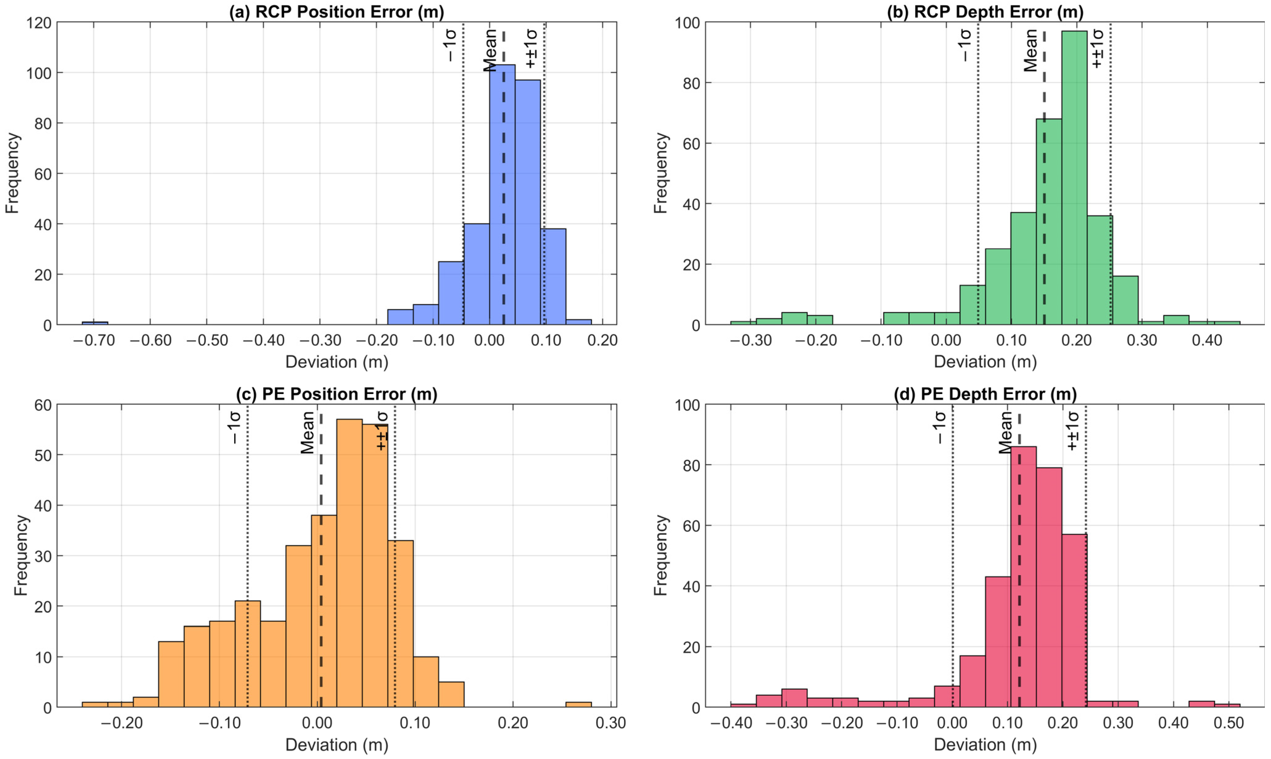
The RCP Position deviation (
Figure 9a) exhibited a tight concentration around the mean value of +0.0161 m with a standard deviation of ±0.0584 m, indicating high consistency in horizontal localization. The RCP Depth deviation (
Figure 9b) showed a slightly broader distribution with a mean of +0.0822 m and a standard deviation of ±0.1213 m, suggesting slightly greater variability in vertical measurements, which is often influenced by soil compaction and the subsurface conditions.
Despite their non-metallic nature and increased detection complexity, the detection of PE pipelines still exhibited excellent precision. The PE Position deviation (
Figure 9c) had a near-zero mean of +0.0029 m with a standard deviation of ±0.0619 m, confirming reliable horizontal detection. Similarly, the PE Depth deviation (
Figure 9d) showed a mean of +0.0975 m and a standard deviation of ±0.1154 m.
These distributions approximate Gaussian behavior, implying that the AML’s error characteristics are random and not skewed by systematic bias. This statistical stability enhances confidence in the reproducibility of the measurements and supports robust integration into field operations.
In addition to visual analysis, root mean square error (RMSE) values were computed to quantify overall measurement accuracy, yielding 0.0602 m for RCP Position, 0.1268 m for RCP Depth, 0.0616 m for PE Position, and 0.1229 m for PE Depth. These low RMSE values reaffirm the AML’s suitability for high-precision detection under regulatory constraints and fall well within the Korean legal tolerances specified in
Table 3.
From a practical perspective, the performance of the AML system reflects not only compliance with regulatory requirements but also technological innovation in subsurface utility detection. The system is capable of identifying both metallic and non-metallic utilities with sub-decimeter accuracy, making it a viable alternative to traditional Ground-Penetrating Radar (GPR) or Electromagnetic Induction (EMI) devices. In particular, the AML system can detect buried utilities at depths reaching up to 3 m, significantly surpassing the typical ~2 m effective detection range of most GPR systems under standard field conditions. Due to signal attenuation and limited penetration capability in real-world soils, GPR systems generally struggle to detect non-metallic utilities at depths exceeding 3 m, making them insufficient for applications requiring compliance with South Korean regulatory standards. Additionally, the AML device has demonstrated consistent performance in detecting both metallic and non-metallic utilities across a variety of environmental and installation scenarios, underscoring its robustness and operational reliability.
4. Discussion
The present study provides a field-based validation of the All Materials Locator (AML) system’s performance in detecting non-metallic pipelines under standardized testbed conditions. In contrast to previous studies focused on metallic utilities or shallow installations, the AML system demonstrated robust accuracy in locating deeply buried polyethylene (PE) pipelines at a 3 m depth—a scenario traditionally problematic for electromagnetic-based methods such as GPR. This outcome underscores the AML’s potential as a regulatory-compliant alternative for subsurface utility detection in challenging environments.
Unlike Ground-Penetrating Radar (GPR), which is sensitive to soil moisture and material conductivity, the AML system demonstrated stable signal acquisition through ultra-high-frequency signal processing based on subsurface density variations. Across 32 repeated trials, the system consistently detected all 10 designated points along the 3 m deep pipelines, with an average vertical depth of 2.524 m for PE and a horizontal reference distance averaging 5.75 m. The low root mean square errors (RMSE) of 0.0616 m for position and 0.1229 m for depth confirm the system’s precision under favorable field conditions.
Histograms and deviation analyses further showed that the measurement errors followed near-Gaussian distributions, indicating random noise characteristics rather than systematic bias. This supports the system’s statistical stability and field reliability. Moreover, the compact, handheld nature of the AML device, combined with real-time visual feedback, enhances its usability in urban construction environments where space and time constraints are common. However, the AML system lacks a visual scanning interface such as the B-scan provided by GPR systems (see
Figure 2). Although no false positives or spurious detections were observed during the trials, the absence of real-time visual feedback made it more challenging to identify the initial scanning area, particularly in zones without surface indicators. In addition, while the AML device includes GPS functionality, post-processing is required to convert the recorded measurements into usable geospatial formats compatible with GIS platforms.
The ability of the AML system to detect non-metallic utilities at depths up to 3 m using a portable platform represents a substantial advancement in underground utility mapping. It offers a promising alternative or complement to GPR- and EMI-based technologies, particularly for infrastructure maintenance, excavation safety, and pre-construction planning.
However, it is important to acknowledge that the field experiments in this study were conducted in decomposed granite soil, which is known to have favorable transmission characteristics. As such, the results represent an ideal-case scenario and may not fully generalize to more complex or adverse soil environments. In real-world scenarios, soils with higher clay content, water saturation, or heterogeneous backfill materials can significantly alter signal propagation, potentially reducing the system’s accuracy and detection range.
To address this limitation, future research should include systematic evaluations across a range of geotechnical conditions, including clayey, silty, and waterlogged soils. These expanded trials will be critical for assessing the AML system’s robustness and validating its broader applicability in urban and non-urban contexts alike.
While the present study focused on detection performance up to the 3 m depth specified by South Korean regulations, the testbed used does not contain buried utilities at depths greater than 3 m. As a result, a sensitivity analysis or success/failure rate assessment beyond this depth could not be performed. Future studies should include extended depth scenarios to evaluate the system’s effectiveness in detecting deeply buried utilities, particularly in contexts where the infrastructure may exceed standard installation depths.
In addition, the integration of AML-derived data with spatial information systems and smart infrastructure frameworks holds significant potential. Recent studies have demonstrated the feasibility of implementing digital twin models for underground utility tunnels using multimodal sensors and BIM–GIS integration [
47]. Similarly, methodologies for geospatial data acquisition and real-time service modeling in digital twin environments have shown that such integration can enhance utility monitoring and operational management [
48]. Future studies should also consider adopting objective performance evaluation methods for underground sensing technologies, as discussed by [
49]. Such standardized frameworks would support the comparison of different detection systems under varied environmental conditions, contributing to more reliable deployment in practice.
5. Conclusions
This study demonstrates the technological innovation of the All Materials Locator (AML) system in the field of underground utility detection. Unlike conventional Ground-Penetrating Radar (GPR) systems, which are often constrained by limited detection depth and material sensitivity—particularly in identifying non-metallic pipelines such as PVC or PE—the AML system employs high-frequency signal analysis to detect subsurface density variations. This novel approach significantly enhances its versatility and detection capacity.
Field evaluations focused on 3 m deep non-metallic pipelines, specifically polyethylene (PE) conduits. The AML system successfully detected all 10 measurement points along each target, with an average depth reading of approximately 2.524 m and a horizontal position averaging 5.75 m from the reference line. Deviation analysis across 32 sample sets confirmed high accuracy: horizontal and vertical deviations for PE pipelines averaged +0.0029 m and +0.0975 m, respectively, with standard deviations well within acceptable tolerance ranges (±0.30 m). The computed RMSE values—0.0616 m for position and 0.1229 m for depth—further reinforced the system’s reliability and measurement consistency.
In addition, histogram-based statistical assessments showed that the deviation distributions closely followed Gaussian behavior, indicating random error characteristics with no systematic bias. These results confirm that the AML system not only provides sub-decimeter accuracy but also offers robust reproducibility in controlled environments, even under the complex detection conditions associated with non-metallic utilities.
The device’s compact, user-friendly design and real-time feedback interface also enhanced field operability, positioning the AML as a practical and efficient alternative to traditional GPR- and EMI-based methods. These findings suggest that the AML system represents a forward-looking advancement in underground utility detection, with significant potential to improve excavation safety, reduce infrastructure damage, and support digital asset management.
Future research should extend these findings by applying the AML system in diverse soil conditions and mixed-utility environments, and by exploring its integration with AI-assisted detection platforms, spatial databases, and digital twin systems to support next-generation smart infrastructure planning.
Author Contributions
Conceptualization, S.-J.L. and H.-S.Y.; methodology, S.-J.L.; software, S.-J.L.; validation, S.-J.L. and H.-S.Y.; formal analysis, S.-J.L.; investigation, S.-J.L.; resources, S.-J.L.; data curation, S.-J.L.; writing—original draft preparation, S.-J.L.; writing—review and editing, H.-S.Y.; visualization, S.-J.L.; supervision, H.-S.Y.; project administration, H.-S.Y.; funding acquisition, H.-S.Y. All authors have read and agreed to the published version of the manuscript.
Funding
This work was supported by the National Research Foundation of Korea (NRF) grant funded by the Korean government (MSIT) (RS-2021-NR059478).
Institutional Review Board Statement
Not applicable.
Informed Consent Statement
Not applicable.
Data Availability Statement
The original contributions presented in this study are included in this article, and further inquiries can be directed to the corresponding authors.
Conflicts of Interest
The authors declare no conflicts of interest.
Correction Statement
This article has been republished with a minor correction to resolve spelling errors. This change does not affect the scientific content of the article.
References
- Park, D.K.; Park, K.H.; Ko, J.S.; Kim, Y.S.; Chung, N.E.; Ahn, Y.W.; Han, S.H. The role of forensic anthropology in the examination of the Daegu subway disaster (2003, Korea). J. Forensic Sci. 2009, 54, 513–518. [Google Scholar] [CrossRef] [PubMed]
- Jeon, G.; Hong, W. Characteristic features of the behavior and perception of evacuees from the Daegu subway fire and safety measures in an underground fire. J. Asian Archit. Build. Eng. 2009, 8, 123–130. [Google Scholar] [CrossRef]
- Lee, E.; Kim, H.; Kim, J. Effectiveness of downward evacuation in a large-scale subway fire disaster: A case study of the Daegu subway fire. Tunn. Undergr. Space Technol. 2011, 26, 133–139. [Google Scholar] [CrossRef]
- Marlair, G.; Le Coze, J.C.; Kim, W.H. The Daegu Metro Fire: A Review of Technical and Organisational Issues, INERIS Technical Report; Institut National de l’Environnement Industriel et des Risques (INERIS): Paris, France, 2004; Available online: https://ineris.hal.science/ineris-00970056 (accessed on 17 April 2025).
- Daniels, D.J. Ground Penetrating Radar, 2nd ed.; The Institution of Engineering and Technology: London, UK, 2004. [Google Scholar] [CrossRef]
- Rasol, M.; Pérez-Gracia, V.; Fernandes, F.M.; Pais, J.C.; Santos-Assunçao, S.; Roberts, J.S. Ground penetrating radar system: Principles. In Handbook of Cultural Heritage Analysis; D’Amico, S., Venuti, V., Eds.; Springer: Cham, Switzerland, 2022; pp. 705–738. [Google Scholar] [CrossRef]
- Liu, X.; Dong, X.; Leskovar, D.I. Ground penetrating radar for underground sensing in agriculture: A review. Int. Agrophys. 2016, 30, 533–543. [Google Scholar] [CrossRef]
- Liu, Y.; Habibi, D.; Chai, D.; Wang, X.; Chen, H.; Gao, Y.; Li, S. A comprehensive review of acoustic methods for locating underground pipelines. Appl. Sci. 2020, 10, 1031. [Google Scholar] [CrossRef]
- Ghanbari, S.; Hafizi, M.K.; Bano, M.; Ebrahimi, A.; Hosseinzadeh, N. An enhanced GPR-based data processing approach for detecting subsurface utilities in urban distribution networks. J. Appl. Geophys. 2022, 206, 104831. [Google Scholar] [CrossRef]
- SSI Locators. All Materials Locator (AML) Product Information. 2024. Available online: https://www.ssilocators.com/product/aml-plus/ (accessed on 17 April 2025).
- Patil, S.; Banerjee, S.; Tallur, S. Smart structural health monitoring (SHM) system for on-board localization of defects in pipes using torsional ultrasonic guided waves. Sci. Rep. 2024, 14, 24455. [Google Scholar] [CrossRef]
- Azhari, H.; Salim, A.; Nour, M.; Hajjar, Y. Investigating New Underground Utility Location Technologies and Their Integration with Existing Systems; University of Pittsburgh: Pittsburgh, PA, USA, 2022; Available online: https://www.engineering.pitt.edu/contentassets/e9b3db3b2163488aaf2e4c50a2f6c640/undeground-utilities-final-report_mod.pdf (accessed on 17 April 2025).
- Kim, K.; Park, D.H.; Lee, J.; Lee, I. Underground facility monitoring services for detecting road subsidence. In Proceedings of the SERVICE COMPUTATION: The Ninth International Conferences on Advanced Service Computing, Athens, Greece, 19–23 February 2017; pp. 32–37. Available online: https://personales.upv.es/thinkmind/dl/conferences/servicecomputation/service_computation_2017/service_computation_2017_2_30_10020.pdf (accessed on 17 April 2025).
- Ge, L.; Zhang, C.; Tian, G.; Xiao, X.; Ahmed, J.; Wei, G.; Hu, Z.; Xiang, J.; Robinson, M. Current trends and perspectives of detection and location for buried non-metallic pipelines. Chin. J. Mech. Eng. 2021, 34, 113. [Google Scholar] [CrossRef]
- Al-Nuaimy, W.; Huang, Y.; Nakhkash, M.; Fang, M.T.C.; Nguyen, V.T.; Eriksen, A. Automatic detection of buried utilities and solid objects with GPR using neural networks and pattern recognition. J. Appl. Geophys. 2000, 43, 157–165. [Google Scholar] [CrossRef]
- Annan, A.P. Chapter 1—Electromagnetic principles of ground penetrating radar. In Ground Penetrating Radar: Theory and Applications, 1st ed.; Jol, H.M., Ed.; Elsevier: Amsterdam, The Netherlands, 2009; pp. 3–40. [Google Scholar] [CrossRef]
- Pringle, J.K.; Stimpson, I.G.; Toon, S.M.; Caunt, S.; Lane, V.S.; Husband, C.R.; Jones, G.M.; Cassidy, N.J.; Styles, P. Geophysical characterization of derelict coalmine workings and mineshaft detection: A case study from Shrewsbury, United Kingdom. Near Surf. Geophys. 2008, 6, 185–194. [Google Scholar] [CrossRef]
- Davis, J.L.; Annan, A.P. Ground-penetrating radar for high-resolution mapping of soil and rock stratigraphy. Geophys. Prospect. 1989, 37, 531–551. [Google Scholar] [CrossRef]
- Annan, A.P. Ground Penetrating Radar Principles, Procedures and Applications; Sensors & Software Inc.: Mississauga, ON, Canada, 2005; Available online: https://geolportal.sdsu.edu/jiracek/sage/documents/Sensors%20and%20Software%20GPR%20Manual.pdf (accessed on 17 April 2025).
- Shamir, O.; Goldshleger, N.; Basson, U.; Reshef, M. Laboratory Measurements of Subsurface Spatial Moisture Content by Ground-Penetrating Radar (GPR) Diffraction and Reflection Imaging of Agricultural Soils. Remote Sens. 2018, 10, 1667. [Google Scholar] [CrossRef]
- Cassidy, N.J. Electrical and Magnetic Properties of Rocks, Soils and Fluids. In Ground Penetrating Radar Theory and Applications; Harry, M.J., Ed.; Elsevier: Amsterdam, The Netherlands, 2009; Chapter 2; pp. 41–72. [Google Scholar] [CrossRef]
- Bano, M.; Dupuis, J.C. GPR signal interpretation in heterogeneous media: Challenges and practical solutions. Near Surf. Geophys. 2017, 15, 577–589. [Google Scholar] [CrossRef]
- Kavi, J.; Halabe, U.B. An approach for easy detection of buried FRP composite/non-metallic pipes using ground-penetrating radar. Sensors 2023, 23, 8465. [Google Scholar] [CrossRef]
- Li, Y.; Zhang, H.; Xu, Z.; Zhang, A.; Liu, X.; Sun, P.; Sun, X. Buried PE pipeline location method based on double-tree complex wavelet cross-correlation delay. Sensors 2024, 24, 7310. [Google Scholar] [CrossRef]
- Li, Y.; Zhang, H.; Xu, Z.; Zhang, A.; Liu, X.; Sun, P.; Sun, X. Location method of buried polyethylene gas pipeline based on acoustic wave attenuation characteristics. Sensors 2024, 24, 7302. [Google Scholar] [CrossRef]
- Zhou, X.; Chen, Q.; Lyu, S.; Chen, H. Estimating the direction and radius of pipe from GPR image by ellipse inversion model. arXiv 2022. [Google Scholar] [CrossRef]
- SubSurface Instruments. All Materials Locator (AML) Product Manual; SubSurface Instruments, Inc.: De Pere, WI, USA, 2024; Available online: https://instecorp.com/catalogs/subsurface-instruments/aml-pro-operators-manual.pdf (accessed on 17 April 2025).
- Instrument Technology Corporation. AML Pro Pipe and Cable Locator. In Technical Brochure; CIGRE: Paris, France, 2024; Available online: https://instecorp.com/catalogs/subsurface-instruments/aml-product-information.pdf?utm_source=chatgpt.com (accessed on 17 April 2025).
- PVC Pipe Locators. AML Pro—PVC Pipe Detector Product Page; PVC Pipe Locators Website: Kingwood, TX, USA, 2024; Available online: https://www.pvcpipelocators.com/finding-pvc-pipes/ (accessed on 17 April 2025).
- Flyability. Ultrasonic Testing: Enhancing Industrial Inspections. Flyability Blog. 2024. Available online: https://www.flyability.com/blog/ultrasonic-testing (accessed on 17 April 2025).
- Sonatest. Principles of Ultrasonic Testing. Sonatest NDT Guide. 2023. Available online: https://sonatest.com (accessed on 17 April 2025).
- Zhang, A.; Zhong, D.; Xu, Z.; Zhang, H. Research on the positioning of buried polyethylene pipelines considering the acoustic attenuation characteristics. Sci. Rep. 2025, 15, 5826. [Google Scholar] [CrossRef]
- Li, X.; Chen, Y.; Zhao, Q. Ultrasonic array tomography-oriented subsurface crack recognition and pixel-wise cross-section image reconstruction for RC structures. NDT E Int. 2023, 135, 102399. [Google Scholar] [CrossRef]
- Wang, L.; Zhou, M.; Li, D. An efficient algorithm embedded in an ultrasonic visualization technique for damage inspection using the AE sensor excitation method. Sensors 2024, 14, 20439. [Google Scholar] [CrossRef]
- Jaufer, R.M.; Ihamouten, A.; Goyat, Y.; Todkar, S.S.; Guilbert, D.; Assaf, A.; Dérobert, X. A preliminary numerical study to compare the physical method and machine learning methods applied to GPR data for underground utility network characterization. Remote Sens. 2022, 14, 1047. [Google Scholar] [CrossRef]
- Seo, H.; Kim, J.; Lee, S. In-line ultrasonic monitoring for sediments stuck on inner wall of a polyvinyl chloride pipe. Sensors 2014, 14, 15813–15826. [Google Scholar] [CrossRef] [PubMed]
- El-Hawwat, S.; Shah, J.K.; Wang, H. Machine learning supported ultrasonic testing for characterization of cracks in polyethylene pipes. Measurement 2025, 213, 112345. [Google Scholar] [CrossRef]
- Yu, Y.; Safari, A.; Niu, X.; Drinkwater, B.; Horoshenkov, K.V. Acoustic and ultrasonic techniques for defect detection and condition monitoring in water and sewerage pipes: A review. Appl. Acoust. 2021, 183, 108282. [Google Scholar] [CrossRef]
- Shah, J.; El-Hawwat, S.; Wang, H. Guided Wave Ultrasonic Testing for Crack Detection in Polyethylene Pipes: Laboratory Experiments and Numerical Modeling. Sensors 2023, 23, 5131. [Google Scholar] [CrossRef]
- Woo, D.K.; Do, W.; Hong, J.; Choi, H. A novel and non-invasive approach to evaluating soil moisture without soil disturbances: Contactless ultrasonic system. Sensors 2022, 22, 7450. [Google Scholar] [CrossRef]
- Shuvalov, A.N.; Lapshinov, A.E.; Zheletdinov, R.R.; Zerkal, E.O. Comparison of ultrasonic and GPR methods for investigation of reinforced concrete columns. BIO Web Conf. 2024, 107, 06016. [Google Scholar] [CrossRef]
- Lin, L. Comparative analysis of ultrasonic testing and ground penetrating radar (GPR) for concrete structure evaluation. Appl. Comput. Eng. 2023, 26, 271–274. [Google Scholar] [CrossRef]
- Long, M.; Jordaan, A.; Castro-Santos, T. Environmental factors influencing detection efficiency of an acoustic telemetry array and consequences for data interpretation. Anim. Biotelemetry 2023, 11, 18. [Google Scholar] [CrossRef]
- Karsznia, K.; Onyszko, K.; Borkowska, S. Accuracy tests and precision assessment of localizing underground utilities using GPR detection. Sensors 2021, 21, 6765. [Google Scholar] [CrossRef]
- Hoon, O.L.L.; Saifuddin, K.; Othman, A.N.; Razali, M.H.; Khalid, N. Accuracy assessment on underground utility equipment. Built Environ. J. 2020, 17, 57–66. [Google Scholar]
- Fenais, A.; Ariaratnam, S.T.; Ayer, S.K.; Smilovsky, N. Integrating geographic information systems and augmented reality for mapping underground utilities. Infrastructures 2019, 4, 60. [Google Scholar] [CrossRef]
- Lee, J.; Lee, Y.; Park, S.; Hong, C. Implementing a digital twin of an underground utility tunnel for geospatial feature extraction using a multimodal image sensor. Appl. Sci. 2023, 13, 9137. [Google Scholar] [CrossRef]
- Lee, J.; Kim, H. Development of geospatial data acquisition, modeling, and service methodology for underground utility tunnels using digital twin technology. Appl. Sci. 2023, 13, 4343. [Google Scholar] [CrossRef]
- Lee, Y.H.; Bae, S.J.; Jung, W.; Cho, J.Y.; Hong, S.H.; Nam, W.S.; Kim, Y.M.; Kim, J.Y. Performance evaluation method for facility inspection and diagnostic technologies. J. Soc. Disaster Inf. 2020, 16, 178–191. [Google Scholar] [CrossRef]
Figure 1.
Principle of GPR.
Figure 1.
Principle of GPR.
Figure 2.
Comparison of GPR B-scan results: (left) Detection of a pipeline buried at 2.0 m, clearly indicated by a hyperbolic reflection pattern within the red circle; (right) No discernible reflection detected at the known location of a polyethylene (PE) pipeline at 3.0 m, highlighted by the yellow dashed box. These results indicate that GPR has limitations in detecting subsurface utilities deeper than 2.0 m under the given soil conditions.
Figure 3.
Schematic illustration of the time-of-flight principle used in subsurface detection. The red solid lines represent the original transmitted wave paths, and the green dashed lines indicate the reflected wave paths from a buried pipeline. This method operates based on the travel time difference between transmitted and reflected signals, similar to the working principle of ultrasonic detection systems.
Figure 4.
Determination of depth with AML equipment.
Figure 4.
Determination of depth with AML equipment.
Figure 5.
Underground utility performance test site and the locations of the installed utilities.
Figure 5.
Underground utility performance test site and the locations of the installed utilities.
Figure 6.
Experimental flowchart of AML-based subsurface utility detection and analysis.
Figure 6.
Experimental flowchart of AML-based subsurface utility detection and analysis.
Figure 7.
Spatial configuration of the underground pipelines and measurement reference points.
Figure 7.
Spatial configuration of the underground pipelines and measurement reference points.
Figure 8.
Heatmaps of AML measurement deviations for RCP and PE pipelines by position and depth, showing 32 samples × 10 points with color intensity centered at zero to illustrate spatial accuracy and consistency.
Figure 8.
Heatmaps of AML measurement deviations for RCP and PE pipelines by position and depth, showing 32 samples × 10 points with color intensity centered at zero to illustrate spatial accuracy and consistency.
Figure 9.
Histograms of AML deviation values: (a) RCP Position, (b) RCP Depth, (c) PE Position, (d) PE Depth. The dashed vertical line indicates the mean, while dotted lines show ±1σ intervals.
Figure 9.
Histograms of AML deviation values: (a) RCP Position, (b) RCP Depth, (c) PE Position, (d) PE Depth. The dashed vertical line indicates the mean, while dotted lines show ±1σ intervals.
Table 1.
Surface projection distances and depths of RCP and PE pipeline targets buried at 3 m.
Table 1.
Surface projection distances and depths of RCP and PE pipeline targets buried at 3 m.
| No. | RCP (3 m)
Position (m) | RCP (3 m)
Depth (m) | PE Pipe (3 m)
Position (m) | PE Pipe (3 m) Depth (m) |
|---|
| 1 | 2.154 | 2.630 | 5.651 | 2.407 |
| 2 | 2.159 | 2.630 | 5.675 | 2.433 |
| 3 | 2.165 | 2.630 | 5.698 | 2.459 |
| 4 | 2.170 | 2.629 | 5.722 | 2.485 |
| 5 | 2.175 | 2.629 | 5.746 | 2.511 |
| 6 | 2.180 | 2.629 | 5.769 | 2.537 |
| 7 | 2.816 | 2.629 | 5.793 | 2.563 |
| 8 | 2.191 | 2.628 | 5.817 | 2.589 |
| 9 | 2.196 | 2.628 | 5.840 | 2.615 |
| 10 | 2.202 | 2.628 | 5.864 | 2.6115 |
Table 2.
Paired deviation values across selected samples for RCP and PE pipelines. Each cell shows the deviation values (in meters) of 2 representative samples among the 32 total samples, illustrating variation in AML measurement performance across different pipeline types and depths.
Table 2.
Paired deviation values across selected samples for RCP and PE pipelines. Each cell shows the deviation values (in meters) of 2 representative samples among the 32 total samples, illustrating variation in AML measurement performance across different pipeline types and depths.
| No. | ΔRCP Position (m) | ΔRCP Depth (m) | ΔPE Position (m) | ΔPE Depth (m) |
|---|
| 1 | −0.001/0.002 | −0.006/−0.086 | 0.031/0.001 | −0.274/−0.314 |
| 2 | 0.032/0.013 | 0.037/−0.023 | −0.017/−0.007 | −0.395/−0.315 |
| ⋮ | ⋮ | ⋮ | ⋮ | ⋮ |
| 10 | −0.058/−0.068 | 0.08/0.2 | −0.014/−0.014 | 0.057/0.167 |
Table 3.
GPR equipment performance evaluation criteria as defined by South Korean regulations.
Table 3.
GPR equipment performance evaluation criteria as defined by South Korean regulations.
| Measuring Equipment | Performance Specification | Remarks |
|---|
| Metallic and Non-metallic Pipeline Detectors | Horizontal Position: ±20 cm | Applicable to pipelines buried at 3 m depth |
| Depth Accuracy: ±30 cm |
| Disclaimer/Publisher’s Note: The statements, opinions and data contained in all publications are solely those of the individual author(s) and contributor(s) and not of MDPI and/or the editor(s). MDPI and/or the editor(s) disclaim responsibility for any injury to people or property resulting from any ideas, methods, instructions or products referred to in the content. |
© 2025 by the authors. Licensee MDPI, Basel, Switzerland. This article is an open access article distributed under the terms and conditions of the Creative Commons Attribution (CC BY) license (https://creativecommons.org/licenses/by/4.0/).


