Article

The Effects of Cutting Pick Parameters on Cutting Head Performance in Tunneling–Bolting Combined Machines

by
Bo Ning
,
Mingzhu Li
and
Jinhua Zhang
*
School of Mechanical and Electrical Engineering, Guangzhou University, Guangzhou 510006, China
*
Author to whom correspondence should be addressed.
Appl. Sci. 2025, 15(10), 5746; https://doi.org/10.3390/app15105746
Submission received: 19 April 2025 / Revised: 18 May 2025 / Accepted: 19 May 2025 / Published: 21 May 2025

Abstract

This paper studies the influence of the pick structure on the cutting characteristics of the cutting head when cutting rocks with a tunneling–bolting combined machine. A simulated model of the breaking of soft rock with a cutting pick was established. Dynamic simulation of the cutting head during the cutting process enabled the force characteristics to be obtained. The validity of the simulation was verified by carrying out cutting experiments. A numerical simulation of the pick parameters made it possible to analyze the influence of the pick’s included angle, taper angle, and established angle on the cutting performance. The results showed that the average values for the cutting resistance and traction resistance when the cutting head cut rocks were 14.21 kN and 7.19 kN, respectively. An included angle of between 70° and 75° was found to be most suitable. Within a specific range, the cutting force was found to increase with an increase in the taper angle. An established angle between 40° and 45° proved to have the highest cutting efficiency. At present, the results have been applied to the Shendong Coalmine. Thus, the proposed model provides a sound theoretical basis for the optimal design of the cutting head.

1. Introduction

Rapid excavation and safe, efficient anchoring support are key preconditions in modern underground space engineering. In the past, tunneling and anchoring were handled separately [1,2]. Now, in order to improve efficiency, tunneling–bolting combined machines have begun to attract significant attention in research and look set to become an important aspect of the development of modern mining technology. However, due to the technical difficulty and expense of constructing such machines, only a very small number of manufacturers are currently able to produce them. As a result, there are very few studies regarding tunneling–bolting combined machines, and geotechnical cutting theory relating to their cutting heads is still in its infancy [3,4,5].
As coal mining machines and anchoring machines bear certain similarities regarding their cutter arrangement and the movement of their roller picks [6,7], some of the theoretical analysis relating to coal mining machines can be used to study the mechanical behavior of the drum cutter in tunneling–bolting combined machines [8,9]. In this regard, Fu, Zhao, and Liu have studied the load characteristics of the shearer picks in coal mining machines [10,11,12]. Liu has established a specific energy consumption model based on the resistance spectrum of shearer picks [13]. Prokopenko has studied the wear characteristics of shearer picks [14]. Liu and Qiao have studied the effect of the pick arrangement on the load, reliability, and likely life-span of shearers [15,16]. Qin studied the influence of housing topological optimization on the dynamic characteristics of the drum driving system [17]. Zeng studied the cutting strategy to lower the influence of cutting forces on the shearer and its drum [18]. Ordin found that in order to improve coal sizing and reduce methane release in the longwall face, as well as for the uniform distribution of loads on picks, the picks should be arranged on the drum at unequal spacing in accordance with the exponential law [19]. Gao has explored the influence of factors such as the helix angle of the shearer cutting head [20,21]. Qin [22], meanwhile, has studied the influence of bit motion parameters on cutting performance. Unlike traditional coal mining machines, there is no helical blade in the cutting head of a tunneling–bolting combined machine, and the fragmentation and mode of conveyance are different, as shown in Figure 1. As a result, the force of the cutting head differs significantly from that of a helical drum during the cutting process.
Rock breaking is a complex and cumulative process, with non-equilibrium and nonlinear characteristics. The main reason that a rock can be broken with a pick lies in its compressive effect on the rock. Specifically, the compressive stress generated in front of the blade quickly destroys the weak connections inside the rock, with the damage gradually accumulating. A constitutive model of this type of damage was proposed by Holmquist, Johnson, and Cook in 1993 (hereinafter referred to as the HJC model). This describes the nonlinear deformation, breakage, and damage of materials like concrete and rock. It also considers the pressure correlation, strain rate effect, and damage softening effect of the material’s compressive strength, which is consistent with the fragmentation characteristics for coal and rock. The HJC model was used by Xia to simulate the process of breaking rock with a cutter [23]. Fang later explored ways of determining its parameters [24]. Li subsequently revised these parameters on the basis of a split Hopkinson pressure bar (SHPB) experiment, so as to make it better-suited to coal and rock [25].
In this paper, a finite element model of cutting rock with the cutting head of a tunneling–bolting combined machine is presented. This model incorporates a constitutive model of rock dynamic compression damage based on a double-failure criterion. Explicit dynamics analysis software was used to simulate the cutting process so as to be able to study the influence of different parameters of the pick on the cutting performance. We analyzed the changes in stress experienced by the tool during the rock-breaking process and identified its optimal characteristics and how the cutting mode and pick structure might therefore be improved.

2. Finite Element Modeling of the Cutting Head Cutting Rock

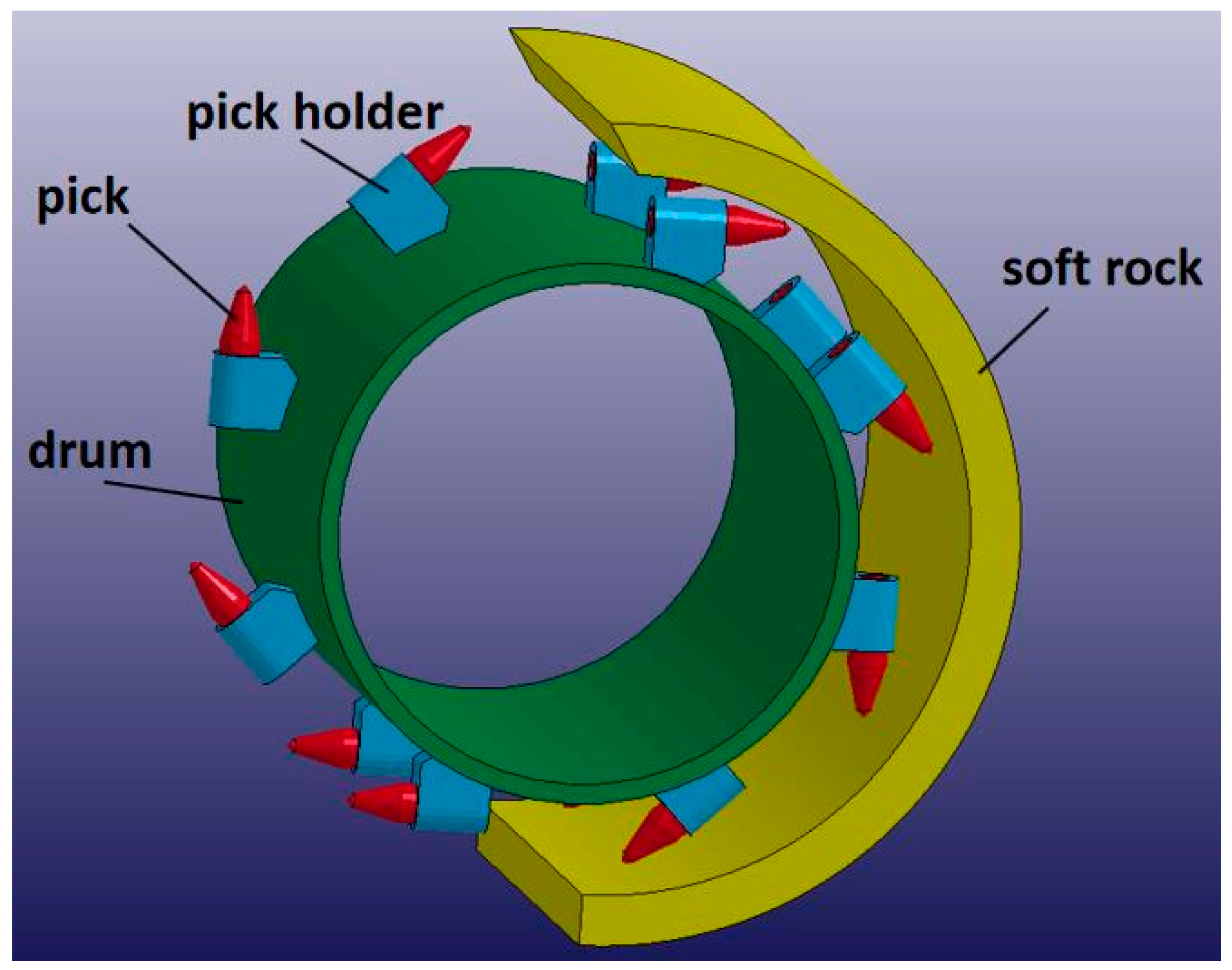
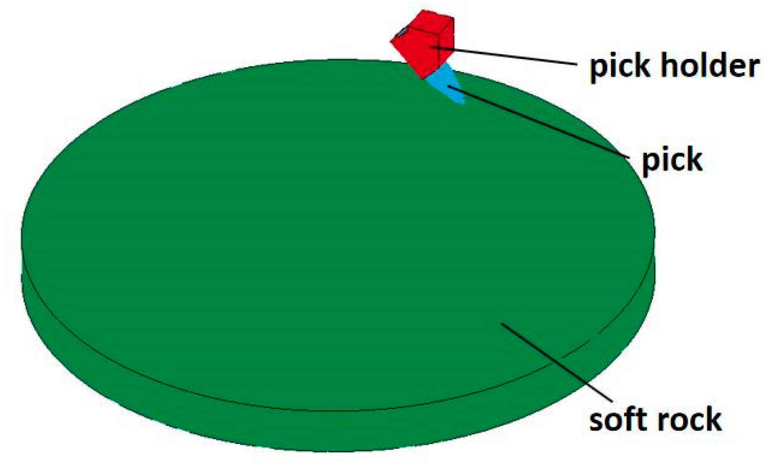
2.1. Establishment of the Model

When a tunneling–bolting combined machine is in operation, the cutting head either moves forward, which is called a translational movement, or it rotates around an axis, which is called a rotational movement. During this process, the trajectory of the pick approximates a helical curve. After the rock is broken, the rock in front of the cutting head is arc-shaped. To study the force of the pick during the cutting process, the rock model was, therefore, designed as an arc. The three-dimensional model is shown in Figure 2.
The cutter consists of a cemented carbide-tipped head and a tool base. The head is brazed to the tool base. As these two components are brazed together, they are also integrated into the model. By defining the picks, pick holder, and drum as rigid materials, the model can be simplified. This saves computation time and has minimal impact on the results. The model uses an eight-node SOLID164 unit and a default constant stress unit formula to define the type of contact between the tool and the soft rock (erosive contact).

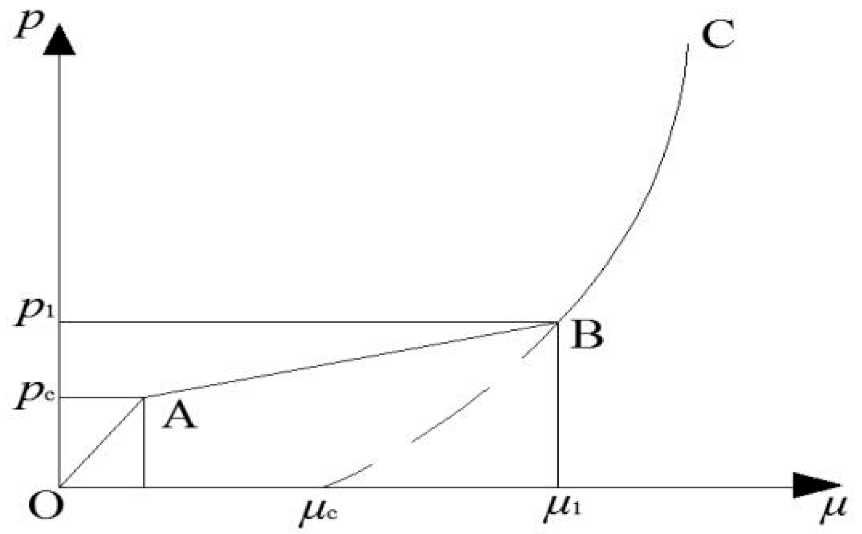
2.2. Determination of the Material Parameters

Drawing upon rock-breaking theory and the principles of explicit dynamic analysis, a finite element model of the soft rock, pick, pick holder, and drum was established. The soft rock was based on the HJC constitutive model of coal and rock. It can be seen from Figure 3 that the compressive deformation of coal can be divided into three stages: elastic deformation (O-A), plastic deformation (A-B), and compaction deformation (B-C). In Figure 3, p refers to the pressure and μ is the volumetric strain.
  • Elastic deformation (0 ≤ μ ≤ μc):
P = ,
K = Pc/μc,
where K is the elastic bulk modulus of the rock, Pc is the crushing pressure of the rock, and μc, is the volume strain of the rock.
2.
Plastic deformation (μcμμ1):
During this stage, the pores in the rock are broken, and the structure of the rock starts to become damaged, but it is not completely broken. Cracks appear in the rock.
Loading process:
P = Pc + K1 (μμc)
K1 = (PcP1)/(μcμ1),
In the above formula, K1 is the plastic bulk modulus of the rock, P1 is the compaction pressure of the rock, and μ1, is the compacted volume strain of the rock.
Unloading process:
P = P0 + [(1 − F) K + FK1] (μμ0),
F = (μ0μc)/(μ1μc),
P0, here, refers to the maximum pressure before the rock is unloaded, and μ0 is the maximum volume strain before the rock is unloaded.
3.
Compaction deformation (μμ1):
At this stage, the rock is completely crushed and compacted.
Loading process:
P = k 1 μ ¯ + k 2 μ ¯ 2 + k 3 μ ¯ 3 ,
μ ¯ = ( μ μ 1 ) / ( 1 + μ c ) ,
k1, k2 and k3 are the pressure coefficients.
Unloading process:
P = k 1 μ ¯ ,
The HJC-based numerical simulation parameters are shown in Table 1. In this paper, the rock samples are taken from a certain engineering site, and all parameters required for simulation are obtained through experiments and literature reviews [26].

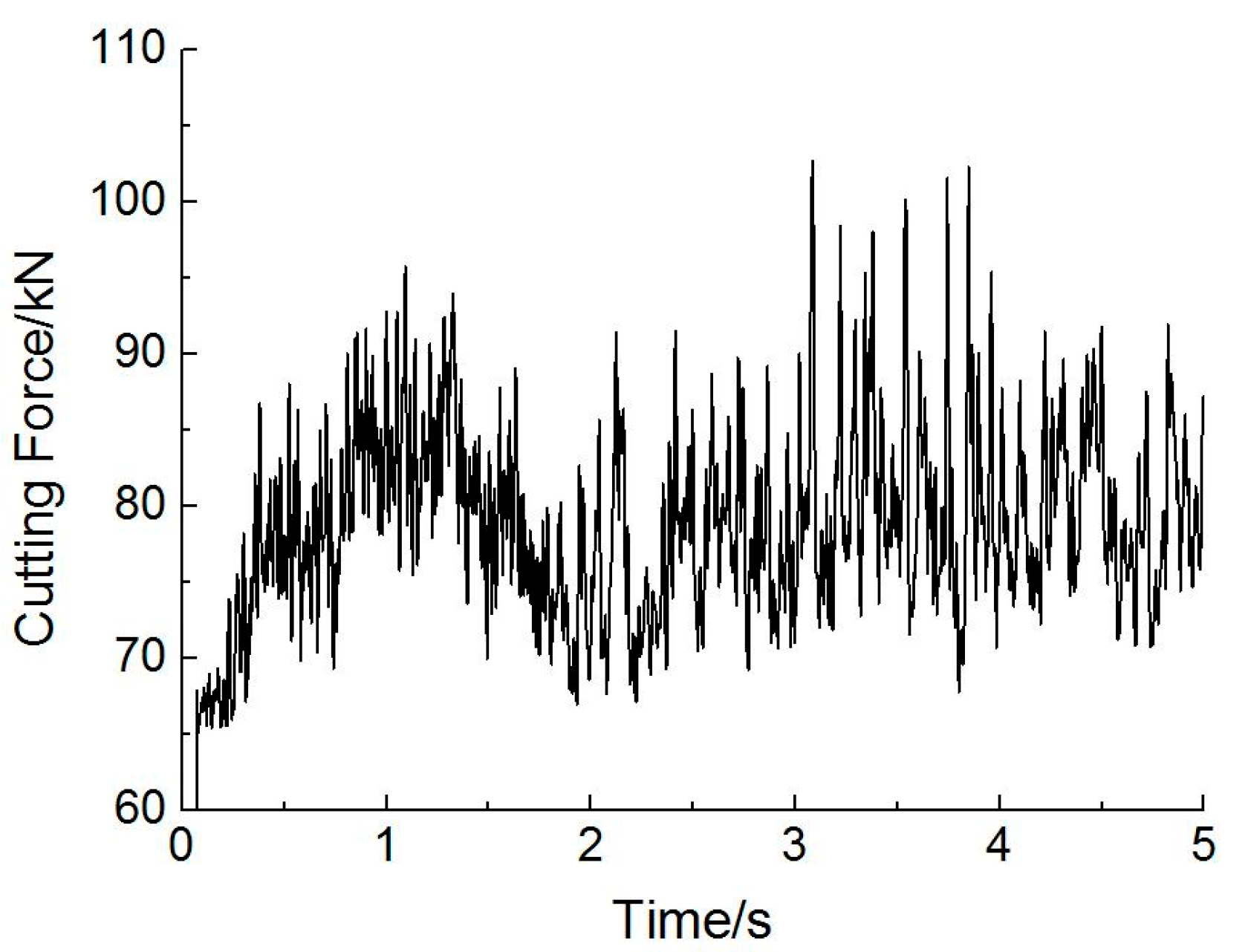
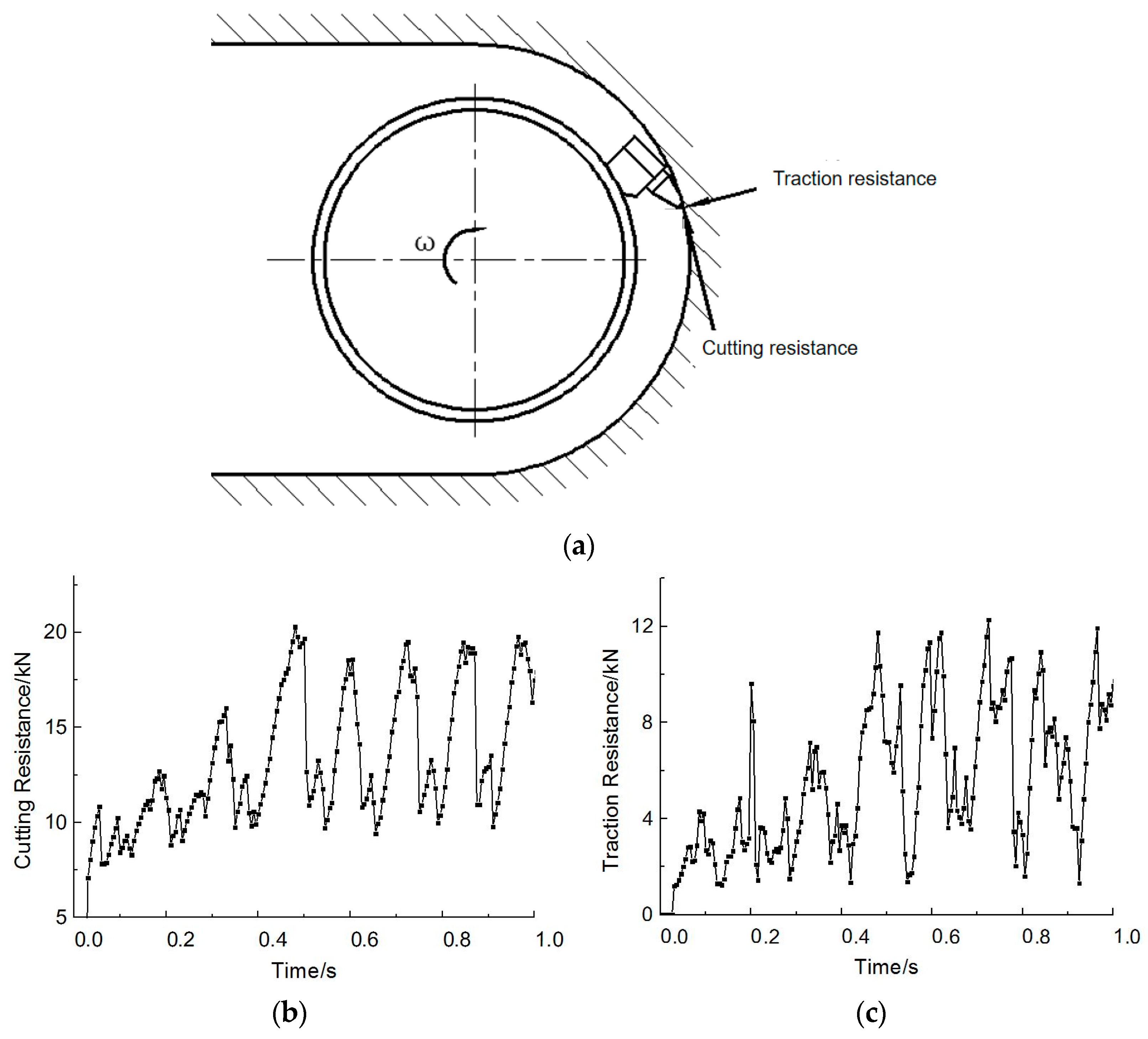
2.3. Simulation Results

The cutting force of the cutting head during rock breaking is shown in Figure 4. It can be seen that the cutting force fluctuates macroscopically during the cutting process because the number of picks acting on the rock is different at different time periods. At 1 s or so, there were six picks cutting the rock at the same time, so the load was relatively large. Only four picks were simultaneously cutting the rock at about 2 s, so the load was relatively small. As the cutting head is subject to vibration because of microscopic fluctuations in the cutting force, a further analysis regarding the fatigue strength of the pick, pick holder, and drum is needed.
As shown in Figure 5, during the rock cutting process, the load exerted by the rock on the cutting pick along the tangential direction of the pick is defined as the cutting resistance, while the load acting along the radial direction toward the center of the drum is defined as the traction resistance. The cutting resistance, traction resistance, and lateral force of a single pick on the cutting head change over time during the rock-breaking process. It can be seen that, during the cutting process, the cutting resistance and the traction resistance fluctuate up and down. This is a basic feature of the cutting force for brittle materials. The force of the cutting head increases noticeably and fluctuates significantly when it first touches the rock. This is because the tool has an existing loading speed during dynamic cutting, and when it touches the rock, it produces a large impact. This results in the pick having a plastic deformation compaction field, and there is a sudden increase in load. At the beginning of the cutting process, both the depth and the applied cutting force are small, so initially, only small pieces of rock are cut. As the cutting head continues to move forward, the cutting depth and the load continue to increase. Similar conclusions can also be found in other studies to support the data presented in this paper [27]. The lateral force is basically balanced by the interaction with the rock on each side of the cutter. According to the fluctuation curve for the cutting resistance and traction resistance obtained by the simulation, the average values for the cutting resistance and traction resistance were 14.21 kN and 7.19 kN, respectively.
The cutting force is one of the most important physical parameters in the cutting process. It determines the amount of power consumed during rock breaking and the fatigue life of the tool. The cutting force also directly affects the heat generated by friction with the rock and the abrasion, breakage, and durability of the tool. The specific energy relating to the cutting process can also indirectly reflect the rock-breaking efficiency of a tunneling–bolting combined machine. The smaller the amount of energy consumed and the larger the area of rock broken, the higher the machine’s rock-breaking efficiency. Thus, properly defining the laws pertaining to variations in the cutting force and the specific energy consumption during cutting will substantially help with the analysis of the rock-breaking process and the selection of appropriate geometric parameters for the picks, all of which are important for guiding the conduct of practical work.

3. Experimental Verification of the Modeling Method and Parameter Settings

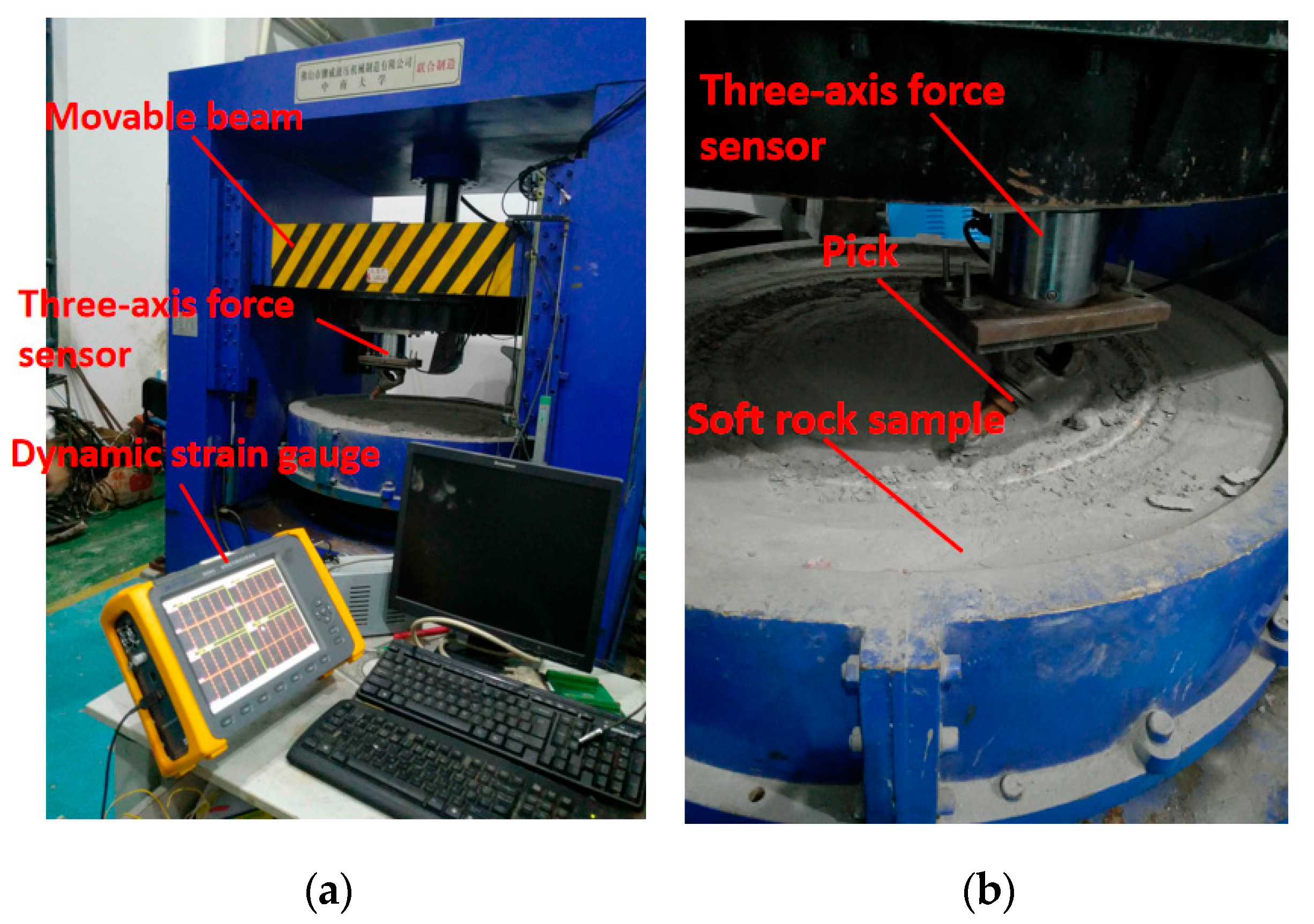
3.1. Experimental Devices

In order to verify the effectiveness of the numerical simulation, an experiment involving the cutting of soft rock was conducted on a workshop-developed rotary cutting experiment bench, as shown in Figure 6. Real-time data relating to the three-axis force of the pick were measured by a three-dimensional force sensor and recorded by a DH5925 dynamic strainmeter(manufactured by DONGHUA, Taizhou, China). The sensor had a range of 0 kN to 60 kN, and the sampling frequency was kept at 200 Hz.

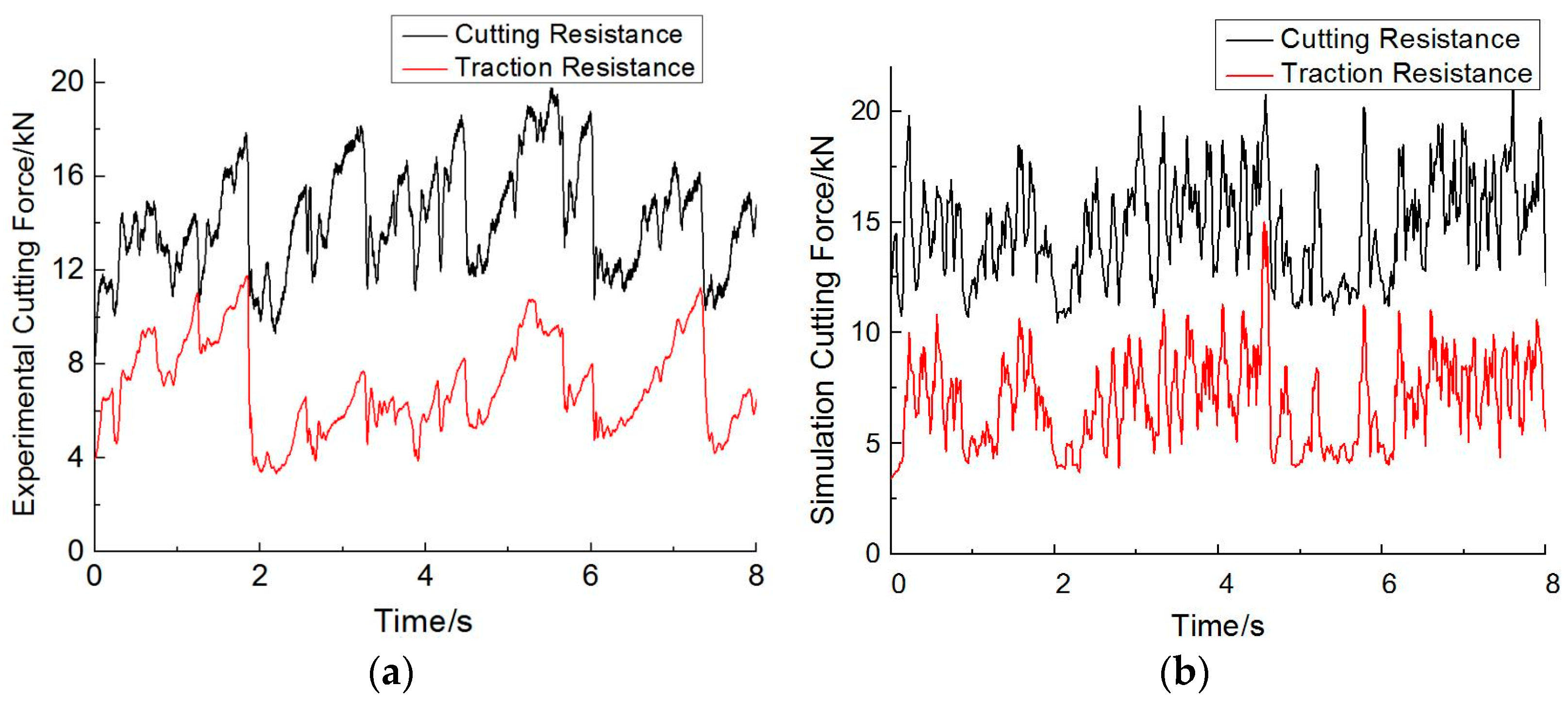
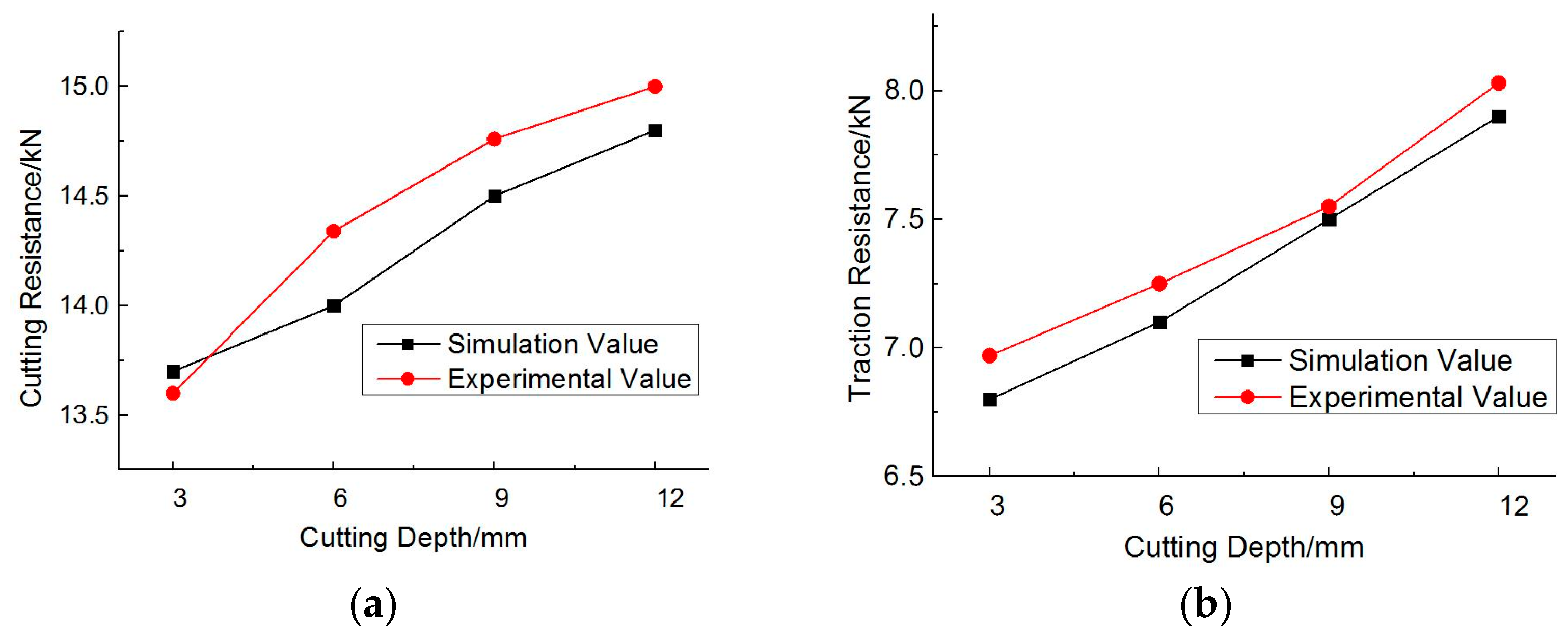
3.2. Comparative Analysis of the Experimental Results

Due to the limitations of the experimental equipment, it was impossible to carry out a complete experiment with the cutting head cutting soft rock. A finite element simulation using the same constitutive model was therefore undertaken, as shown in Figure 7. This enabled us to verify the validity of the simulated model by comparing the experimental results with those generated by the simulation.
The cutting force curves, according to different cutting depths for the physical experiment and the simulation, are shown in Figure 8, respectively. By comparing the two, it can be seen that both cutting force curves have a step change and maintain much the same amplitude, as shown in Figure 9. On top of this, it can be seen from Figure 9 that the average values for the cutting resistance and traction resistance display the same trends. Thus, the simulation results are consistent with the experimental ones. The maximum error between the two sets of results occurred when the cutting depth was 6 mm. At this point, the cutting resistance values for the physical experiment and the simulation were 14.5 kN and 13.9 kN, respectively. However, this difference is still less than 5%. Therefore, the experiment proved the effectiveness of the approach to simulation and the accuracy of the simulated model, allowing for a minimal error tolerance.

4. Influence of the Pick Parameters on the Cutting Force

An analysis of the results suggested that the main geometric parameters that affect the cutting force of the pick are the pick’s included angle, its taper angle, and its established angle, as shown in Figure 10. To assess the effect of these various factors on the cutting force, a numerical simulation was carried out using the parameter values shown in Table 2.

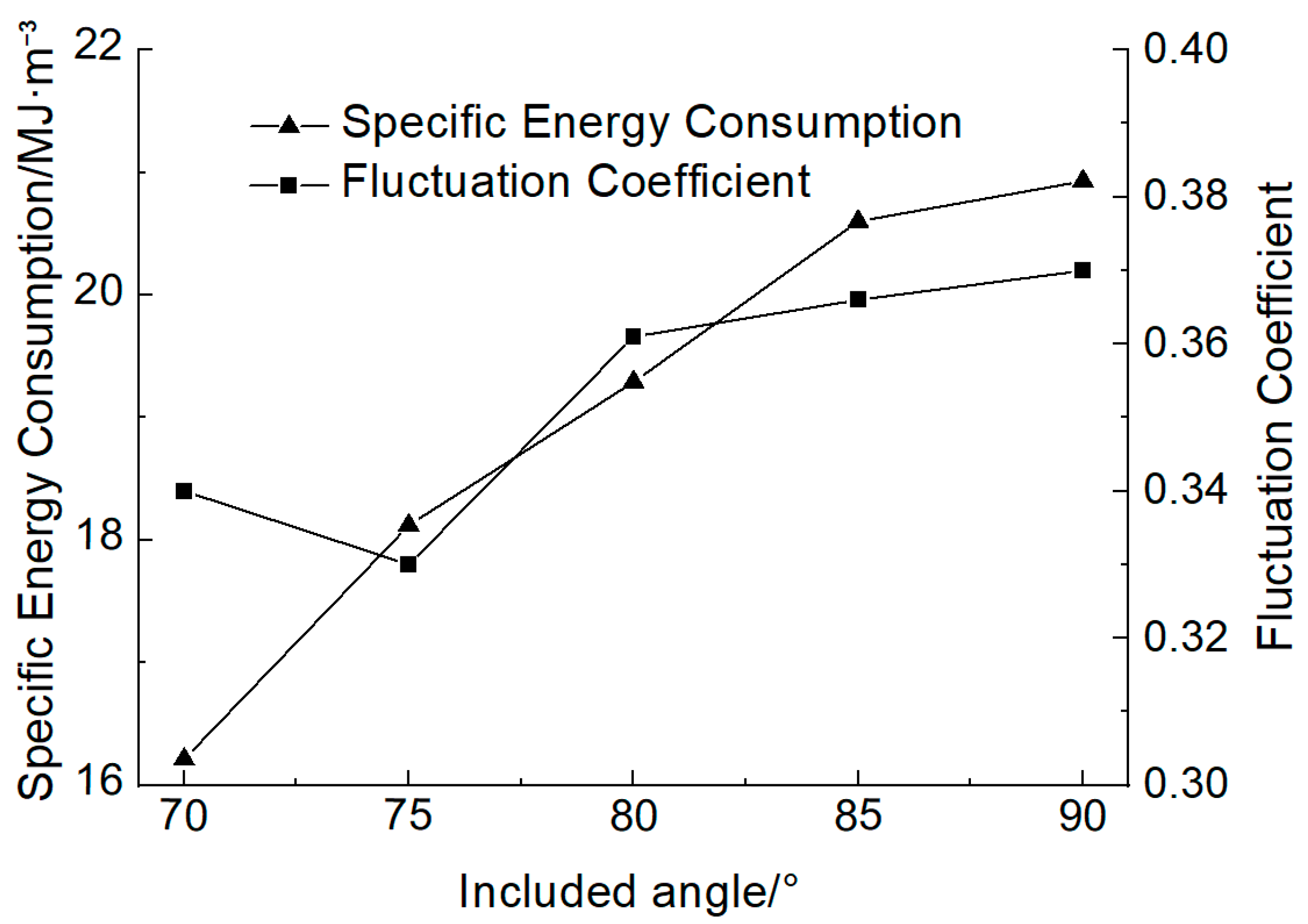
4.1. Influence of the Included Angle on the Cutting Force

The curve for changes in the cutting force relating to the pick’s included angle, based on the above simulation parameters, is shown in Figure 11. It can be seen that as the pick’s included angle increased, the cutting force also increased. This is because the larger the included angle, the greater the contact area between the tool and the rock, resulting in less pressure on the rock per unit area. Therefore, a bigger cutting force is needed to break the rock. However, the pick strength decreases with any decrease in the included angle, so there is a trade-off between the tool strength and minimizing the included angle. The fluctuation coefficient affects the fatigue wear of the pick, so that a smaller fluctuation coefficient can reduce the fatigue wear. Figure 12 shows that when the pick’s included angle was 75°, the fluctuation coefficient of the tool was at its minimum. At the same time, the specific energy consumption of the pick increases as the included angle increases. Taking the cutting force, fatigue wear, and fluctuation coefficient into consideration, the included angle of the pick should be in the range of 70° to 75°.

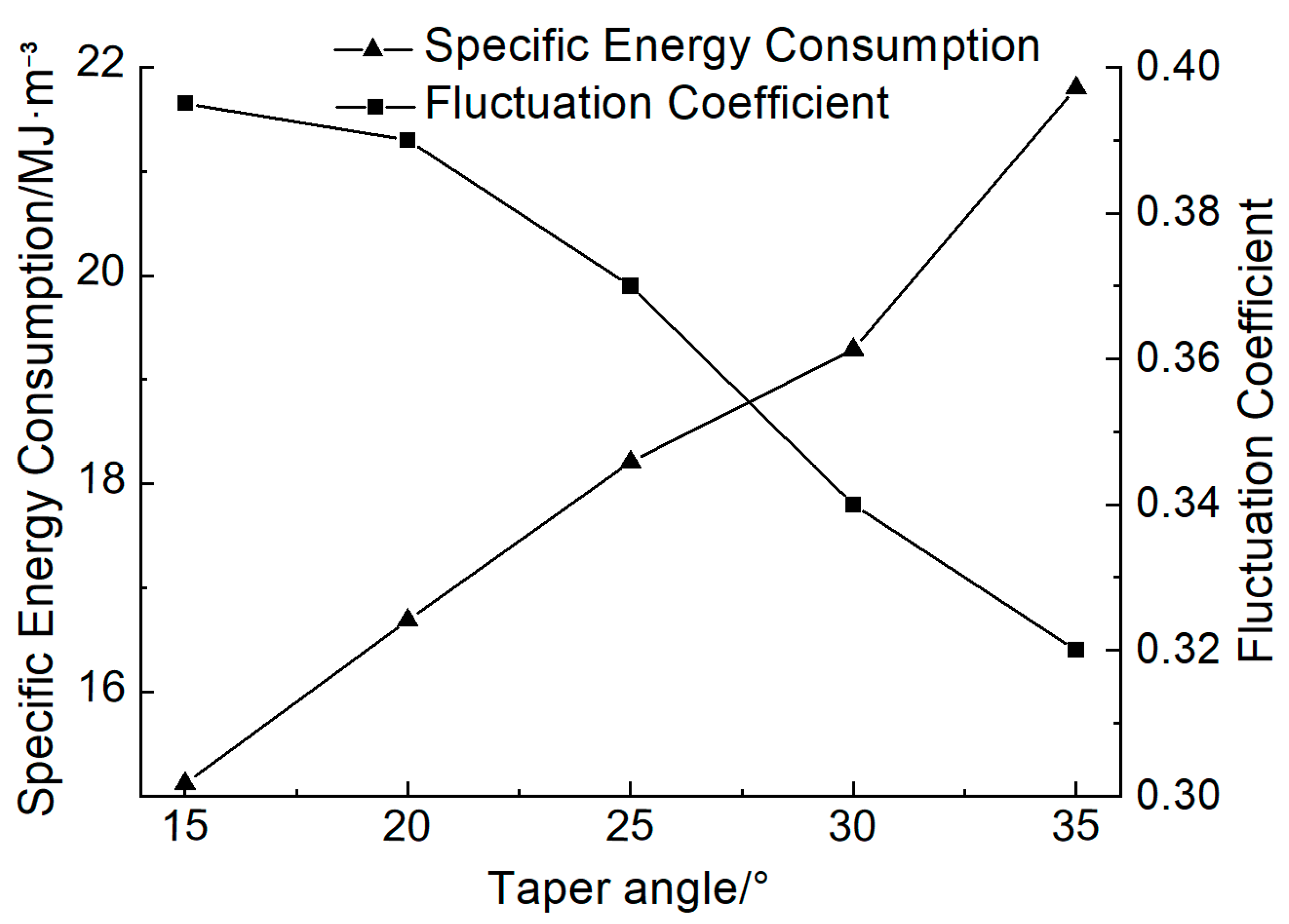
4.2. The Influence of the Taper Angle on the Cutting Force

The simulation parameters from Table 2 can be used to obtain the curve for the changes in cutting force according to the different pick taper angles, as shown in Figure 13. It can be seen that as the taper angle increases, the average and maximum value of the cutting force increases, but the fluctuation coefficient decreases. Thus, increases in the taper angle have a negative effect upon the cutter being able to break into the rock, but help to increase the stability of the process. Figure 14 shows the changes in the specific energy consumption and fluctuation coefficient according to the taper angle. Both the cutting force and fluctuation coefficient need to be carefully considered for tool design. On the basis of these two factors, the taper angle of the pick needs to be in the range of 25° to 30°.

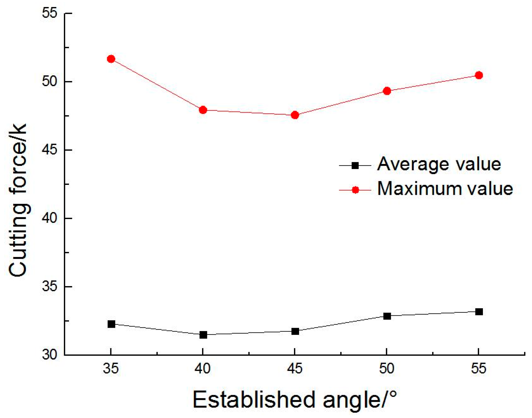
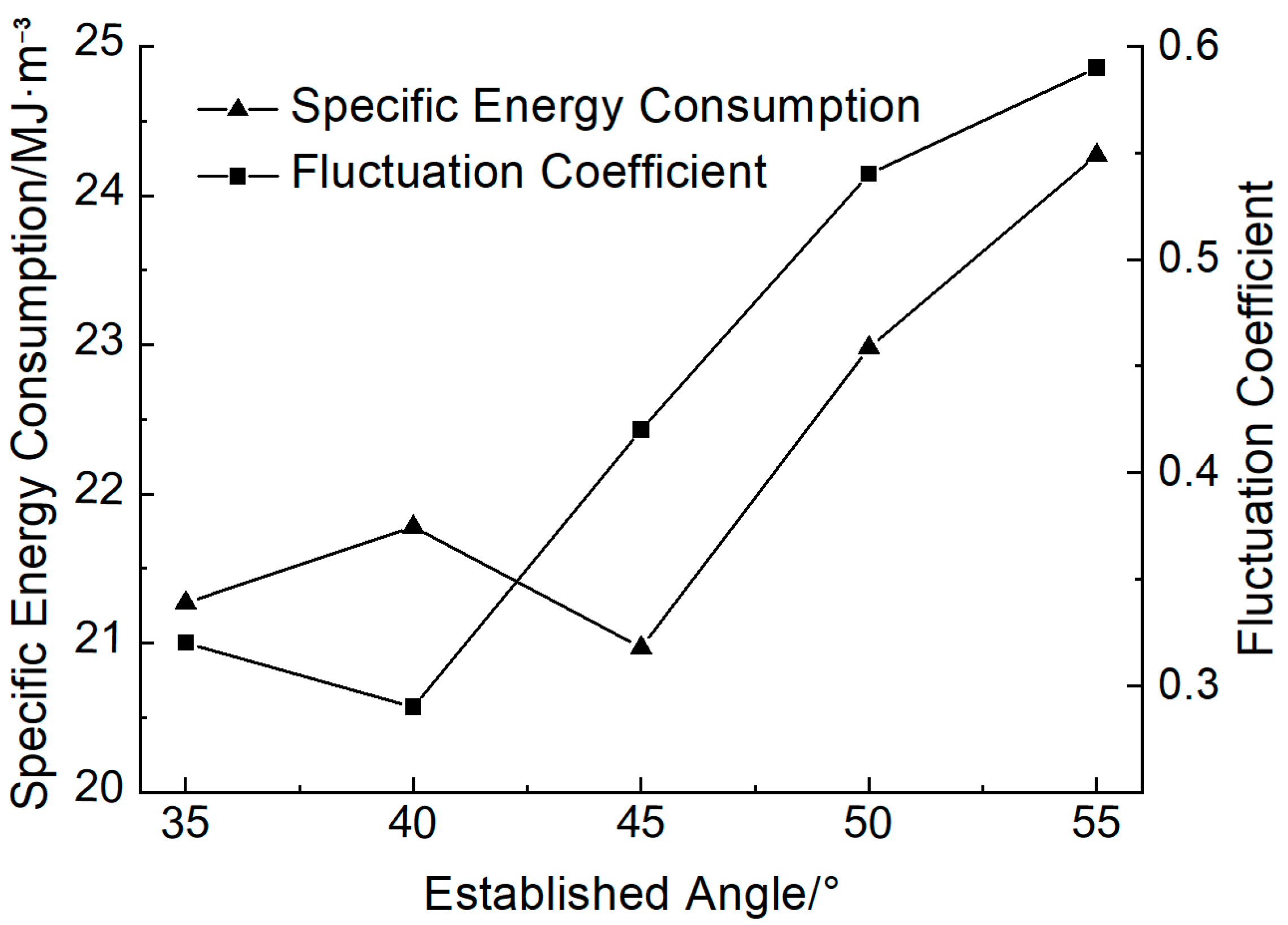
4.3. The Influence of the Established Angle on the Cutting Force

By using the simulation parameters from Table 2, the curve representing the changes in the cutting force according to the established angle can be obtained, as shown in Figure 15. In this case, as the established angle increases, the cutting force initially decreases, then increases, with the minimum value remaining between 40° and 45°. This is because the larger the established angle, the greater the angle between the cutter axis and the rock, which hinders the cutter from breaking into the rock. At the same time, the smaller the established angle, the bigger the contact area between the flank and the rock, leading to more friction. As shown in Figure 16, when the established angle reaches 45°, the pick has the lowest specific energy consumption, and when the established angle is 40°, the fluctuation coefficient reaches its minimum. It can be deduced from this that the optimal value of the established angle will fall within the range of 40° to 45°.

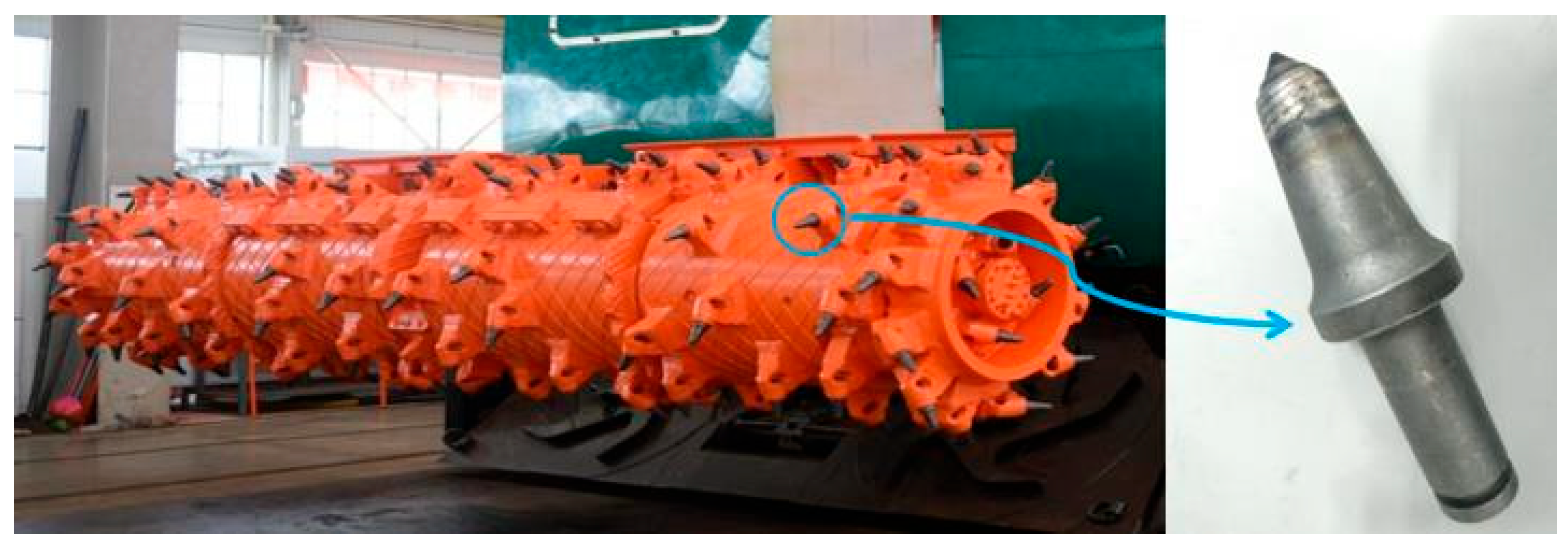
5. Engineering Application

As shown in Figure 17, the structural parameters of the pick equipped with the tunneling–bolting combined machines are the included angle of 75°, the taper angle of 25°, and the established angle of 45°. At present, the tunneling–bolting combined machines have been operating in a certain coal mine in China. During the tunneling process, the cutting head uses a 1 m cycle, the advancing speed can be adjusted for the whole load, and the actual operating speed of the machinery does not exceed 8 m/min. The monthly advancement reaches 3600 m. The machinery operates well, and its crushing capability is good. The results indicate that the finite element models based on the double-failure criterion can effectively predict the cutting head performance and provide a sound theoretical basis for the optimal design of the cutting head.

6. Conclusions

1. In this paper, a constitutive model for the dynamic compression damage of soft rock has been proposed that is based on a double-failure criterion. The model accurately reflects the failure mechanism for coal during the cutting process. Curves depicting the cutting resistance and traction resistance were obtained by means of an FEM simulation. These revealed fluctuations up and down. It was found that the variations in the applied forces are consistent with the theory of rock breaking using picks.
2. By analyzing the influence of a pick’s geometric parameters on the cutting force, we found that the included angle is proportional to the cutting force. Thus, the cutting force increases as the included angle increases. However, the pick’s included angle also needs to be considered. Here, it was found that the pick is more likely to suffer wear with a smaller included angle. An included angle of between 70° and 75° proved to be optimal when taking the influence of the fluctuation coefficient into account. The pick’s taper angle is also directly proportional to the cutting force, with any increase in the angle provoking an increase in the cutting force. The effect of the fluctuation coefficient of the taper angle was also considered, and it was found that a taper angle of between 25° and 30° is best. Finally, as the established angle increases, there is an initial increase in cutting force that is followed by a decrease. The minimum value of the cutting force appeared when the established angle was within the range of 40° to 45°.
3. The laws describing the influence of each of the parameters on the cutting force that were obtained through a simulation of the cutting process provide an effective resource for the rational selection of the optimal geometric and structural parameters when designing future picks for rock breaking.

Author Contributions

B.N.: Writing—original draft, Writing—review and editing, Software, Funding acquisition, Conceptualization, Methodology, and Data curation. M.L.: Investigation, Data curation, Software, and Formal analysis. J.Z.: Writing—review and editing, Investigation, Conceptualization, Methodology, Validation, and Formal analysis. All authors have read and agreed to the published version of the manuscript.

Funding

This study was supported by the National Natural Science Foundation of China (grant number 52304128), the Guangdong Basic and Applied Basic Research Foundation (grant number 2023A1515011821), and the Guangzhou Basic and Applied Basic Research Project (grant number 2024A04J3446).

Data Availability Statement

The original contributions presented in this study are included in the article. Further inquiries can be directed to the corresponding author.

Conflicts of Interest

The authors declare no conflicts of interest.

References

  1. Bertingnoll, H. Alpine bolter miner Austrian technology for rapid roadway development. Min. Technol. 1995, 77, 163–165. [Google Scholar]
  2. Vierhaus, R.; Terbach, G. Development of a high-performance drivage by “Bolter-Miner” technology. Gluckauf Die Fachzeitschrift fur Rohstoff Bergbau und Energie 2002, 138, 425–429. [Google Scholar]
  3. Baldwin, J. Innovation in roofbolted development roadways the Voest Alpine ABM 20 continuous miner bolter. CIM Bull. 1996, 89, 40–45. [Google Scholar]
  4. Leeming, J.J.; Flook, S.D.; Altounyan, P. Bolter miners for longwall development. Gluckauf Die Fachzeitschrift fur Rohstoff Bergbau und Energie 2001, 137, 633–637. [Google Scholar]
  5. Mogk, E.; Eberhard, M.; Kulassek, M.; Michael, A.C. Bolter miner operation at Walsum colliery. Gluckauf Die Fachzeitschrift fur Rohstoff Bergbau und Energie 2002, 138, 436–440. [Google Scholar]
  6. Shao, W.; Li, X.; Sun, Y.; Huang, H. Parametric study of rock cutting with SMART*CUT picks. Tunn. Undergr. Space Technol. Inc. Trenchless Technol. Res. 2017, 61, 134–144. [Google Scholar] [CrossRef]
  7. Yasar, S.; Yilmaz, A.O. A Novel Mobile Testing Equipment for Rock Cuttability Assessment: Vertical Rock Cutting Rig (VRCR). Rock Mech. Rock Eng. 2017, 50, 857–869. [Google Scholar] [CrossRef]
  8. Balci, C.; Bilgin, N. Correlative study of linear small and full-scale rock cutting tests to select mechanized excavation machines. Int. J. Rock Mech. Min. Sci. 2007, 44, 468–476. [Google Scholar] [CrossRef]
  9. Bilgin, N.; Demircin, M.A.; Copur, H.; Balci, C.; Tuncdemir, H.; Akcin, N. Dominant rock properties affecting the performance of conical picks and the comparison of some experimental and theoretical results. Int. J. Rock Mech. Min. Sci. 2006, 43, 139–156. [Google Scholar] [CrossRef]
  10. Fu, L.; Du, C.L.; Liu, S.Y.; Luo, C.X. Research on load characteristics of picks on auger drill miner’s aiguille. China Mech. Eng. 2013, 24, 2021–2024. [Google Scholar]
  11. Zhao, L.J.; He, J.J.; Li, F.Q. Numerical simulation of coal breaking process of plow bit. J. China Coal Soc. 2012, 37, 878–883. [Google Scholar]
  12. Liu, S.Y. Method to determine installing angle of conical point attack pick. J. Cent. South Univ. 2012, 18, 1994–2000. [Google Scholar] [CrossRef]
  13. Liu, C.S.; Wang, Q.H.; Li, D. Fractal characteristic and specific energy model of conical picks cutting resistance spectrum. J. China Coal Soc. 2015, 40, 2623–2628. [Google Scholar]
  14. Prokopenko, S.A.; Ludzish, V.S.; Kurzina, I.A. Improvement of picks to enhance performance of heading machines in rocks. J. Min. Sci. 2016, 52, 153–159. [Google Scholar] [CrossRef]
  15. Liu, S.Y.; Du, C.L.; Cui, X.X. Experimental research on picks arrangement of shearer drum. J. Cent. South Univ. 2009, 40, 1281–1287. [Google Scholar]
  16. Qiao, S.; Xia, Y.M.; Liu, Z.Z.; Liu, J.S.; Ning, B.; Wang, A.L. Performance evaluation of bolter miner cutting head by using multicriteria decision-making approaches. J. Adv. Mech. Des. Syst. Manuf. 2017, 11, 59. [Google Scholar] [CrossRef]
  17. Qin, D.T.; Jia, H.J. Hybrid dynamic modeling of shearer’s drum driving system and the influence of housing topological optimization on the dynamic characteristics of gears. J. Adv. Mech. Des. Syst. Manuf. 2018, 12, 20–29. [Google Scholar] [CrossRef]
  18. Zeng, Q.L.; Jiang, K.; Gao, K.D.; Wan, L.R. Dynamic characteristics analysis on shearer drum in condition of cutting coal with different distributed rocks. J. Vibroeng. 2018, 20, 2796–2809. [Google Scholar] [CrossRef]
  19. Ordin, A.A.; Nikol’sky, A.M. Optimizing Cutting Width and Capacity of Shearer Loaders in Longwall Mining of Gently Dipping Coal Seams. Sci. Min. Mach. 2018, 54, 69–76. [Google Scholar] [CrossRef]
  20. Gao, K.D. Model test of helical angle effect on coal loading performance of shear drum. Int. J. Min. Sci. Technol. 2012, 22, 165–168. [Google Scholar]
  21. Gao, K.D.; Du, C.L.; Liu, S.Y.; Fu, L. Analysis on significance of the factors influencing shearer drum cutting performance. Int. J. Oil Gas Coal Technol. 2014, 7, 386–398. [Google Scholar] [CrossRef]
  22. Qin, D.T.; Wang, Z.; Hu, M.H.; Liu, C.; Ge, S.S. Dynamic matching of optimal drum movement parameters of shearer based on multi-objective optimization. J. China Coal Soc. 2015, 40, 532–538. [Google Scholar]
  23. Xia, Y.M.; Xue, J.; Zhou, X.W. 3-D dimensional numerical simulation of soft rock cutting process. J. Chang Univ. 2010, 30, 102–106. [Google Scholar]
  24. Fang, Q.; Kong, X.-Z.; Wu, H.; Gong, Z. Determination of Holmquist-Johnson-Cook consitiutive model parameters of rock. Eng. Mech. 2014, 31, 179–204. [Google Scholar]
  25. Li, C.W.; Wang, J.G.; Xie, B.J. Numerical simulation of SHPB tests for coal by using HJC model. J. Min. Saf. Eng. 2016, 33, 158–164. [Google Scholar]
  26. Hanchak, S.J.; Forrestal, M.J.; Young, E.R.; Ehrgott, J.Q. Perforation of concrete slabs with 48 MPa (7 ksi) and 140 MPa (20 ksi) unconfined compressive strengths. Int. J. Impact Eng. 1992, 12, 1–7. [Google Scholar] [CrossRef]
  27. Alexis, K.; Gilles, P.; Shehab, A. Experimental investigation of the rock cutting process and derivation of the 3D spatial distribution of the formation strength using in-cutter sensing. J. Pet. Explor. Prod. Technol. 2024, 14, 365–380. [Google Scholar]
Figure 1. Cutting head of a tunneling–bolting combined machine.
Applsci 15 05746 g001
Figure 2. Three-dimensional model.
Applsci 15 05746 g002
Figure 3. HJC model-based pressure–volume strain curve.
Applsci 15 05746 g003
Figure 4. Force curve for the drum.
Applsci 15 05746 g004
Figure 5. Variation in the cutting force of the cutting head over time with regard to (a) the force diagram, (b) the cutting resistance and (c) traction resistance.
Applsci 15 05746 g005
Figure 6. Rotary cutting test bed: (a) The overall structure of the experiment bench, and (b) the rock-breaking part of the experimental bench.
Applsci 15 05746 g006
Figure 7. Experimental verification of the finite element simulation.
Applsci 15 05746 g007
Figure 8. Rock breaking load according to (a) the physical experiment and (b) the simulated mode.
Applsci 15 05746 g008
Figure 9. Comparison of the cutting force curves for the experiment and the simulated model: (a) cutting resistance and (b) traction resistance.
Applsci 15 05746 g009
Figure 10. Geometric parameters for the pick: (a) the included angle, (b) the taper angle, and (c) the established angle.
Applsci 15 05746 g010
Figure 11. Variations in the cutting force according to different pick angles.
Applsci 15 05746 g011
Figure 12. Differences in the pick’s specific energy consumption and fluctuation coefficient according to the included angle.
Applsci 15 05746 g012
Figure 13. Variations in the cutting force according to the taper angle.
Applsci 15 05746 g013
Figure 14. Differences in the specific energy consumption and fluctuation coefficient according to the taper angle.
Applsci 15 05746 g014
Figure 15. Cutting force for different established angles.
Applsci 15 05746 g015
Figure 16. Specific energy consumption and fluctuation coefficient according to the established angle.
Applsci 15 05746 g016
Figure 17. The cutting head used in Shendong Coalmine.
Applsci 15 05746 g017
Table 1. HJC numerical simulation parameters.
ParametersValueParametersValue
ρ (kg/m3)1594 ε f min 0.01
G (Pa)5.8 × 10⁸T (Pa)1.86 × 10⁶
Fc (Pa)9 × 10⁶Pcrush (Pa)3 × 10⁶
A0.4 μ c r u s h 8 × 10⁻⁴
B0.7Plock (Pa)1 × 10⁹
C0.005 μ l o c k 0.12
N0.5k1 (Pa)8.5 × 1010
Smax7k2 (Pa)−1.7 × 10⁻¹¹
D10.0031k3 (Pa)2.08 × 10¹¹
D21EPSO60
In the above table: ρ is the density of the rock; G is the shear modulus of the rock; Fc is the static yield strength of the rock (compressive strength); Smax is the maximum dimensionless strength; A is the dimensionless viscosity constant; B is the dimensionless pressure enhancement coefficient; C is the strain rate coefficient; N is the dimensionless pressure hardening exponent; D1, D2, and ε f min are the material damage constants; k1, k2, and k3 are pressure coefficients; Pcrush, and μ c r u s h are the pressure and volume strain at the crushing point; Plock and μ l o c k are the pressure and volume strain at the compaction point of the material; T is the pressure constant (tensile strength).
Table 2. Simulation of cutting parameter values.
Pick Simulation ParametersParameter Values
Included angle/(°)70, 75, 80, 85, 90
Taper angle/(°)15, 20, 25, 30, 35
Established angle/(°)35, 40, 45, 50, 55
Disclaimer/Publisher’s Note: The statements, opinions and data contained in all publications are solely those of the individual author(s) and contributor(s) and not of MDPI and/or the editor(s). MDPI and/or the editor(s) disclaim responsibility for any injury to people or property resulting from any ideas, methods, instructions or products referred to in the content.

