

Pore-Scale Gas–Water Two-Phase Flow Mechanisms for Underground Hydrogen Storage: A Mini Review of Theory, Experiment, and Simulation


Abstract
1. Introduction
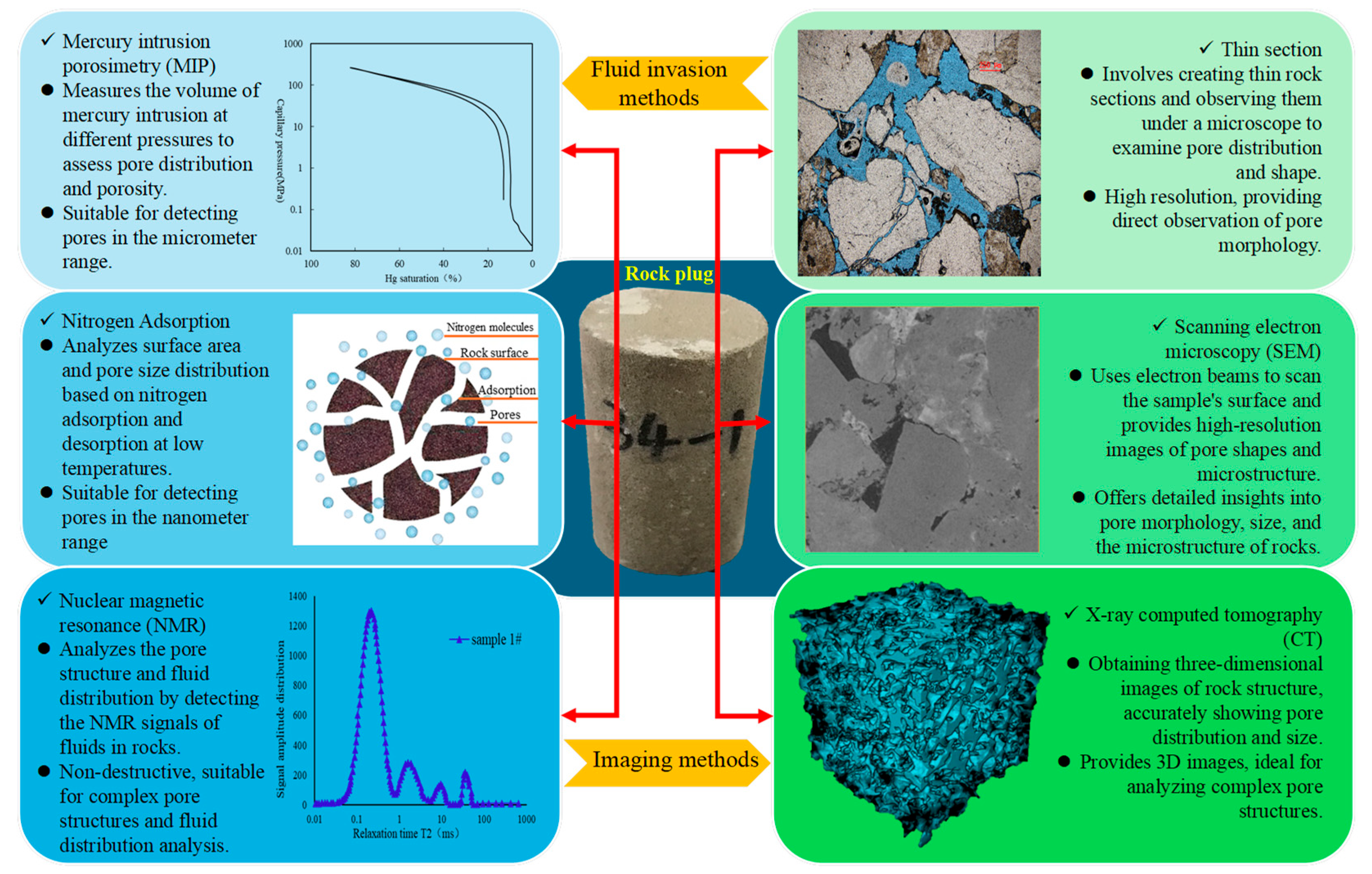
2. Acquisition and Characterization of Pore Structure
2.1. Mercury Intrusion Porosimetry
2.2. Nitrogen Adsorption
2.3. Nuclear Magnetic Resonance
2.4. Thin Section
2.5. SEM
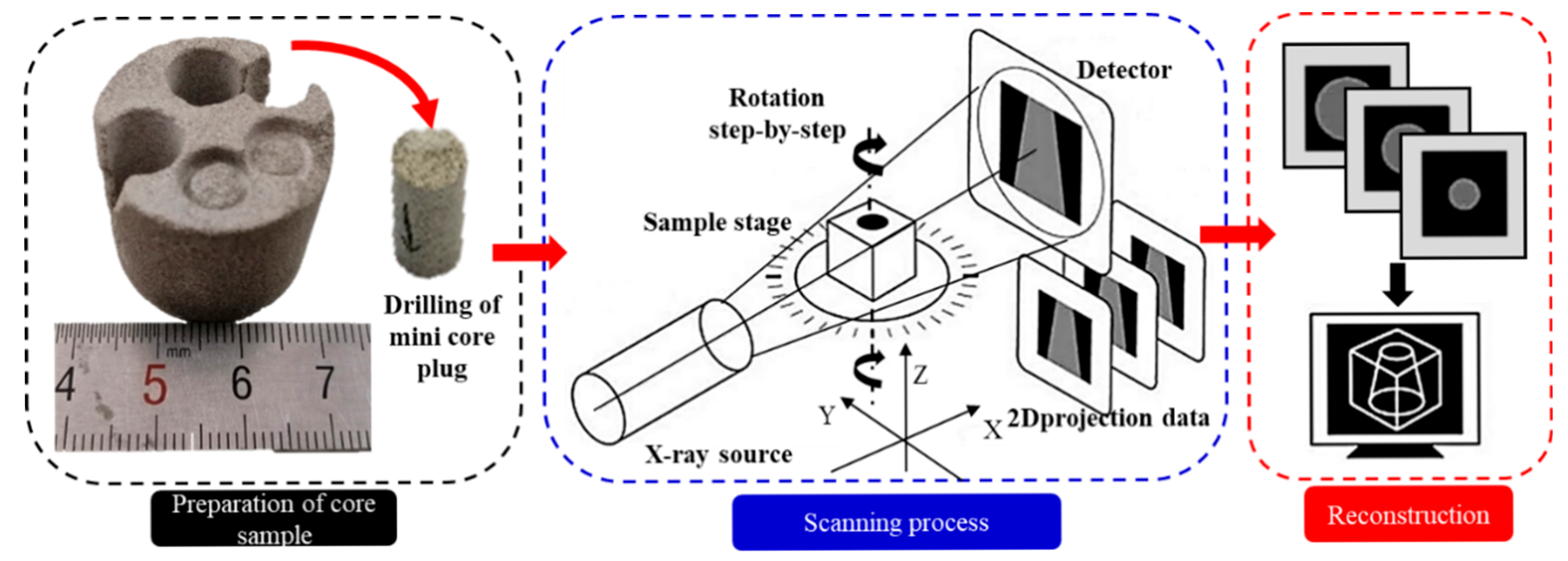
2.6. CT Scanning
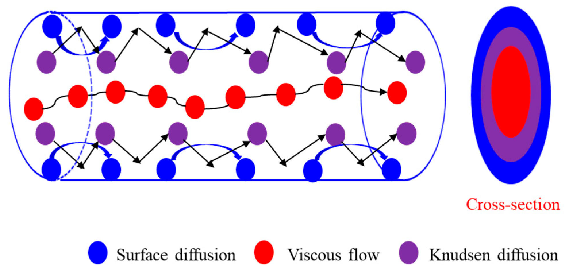
3. Theoretical Model of Fluid Flow in Porous Media
4. Pore-Scale Visualized Experiments for Two-Phase Flow
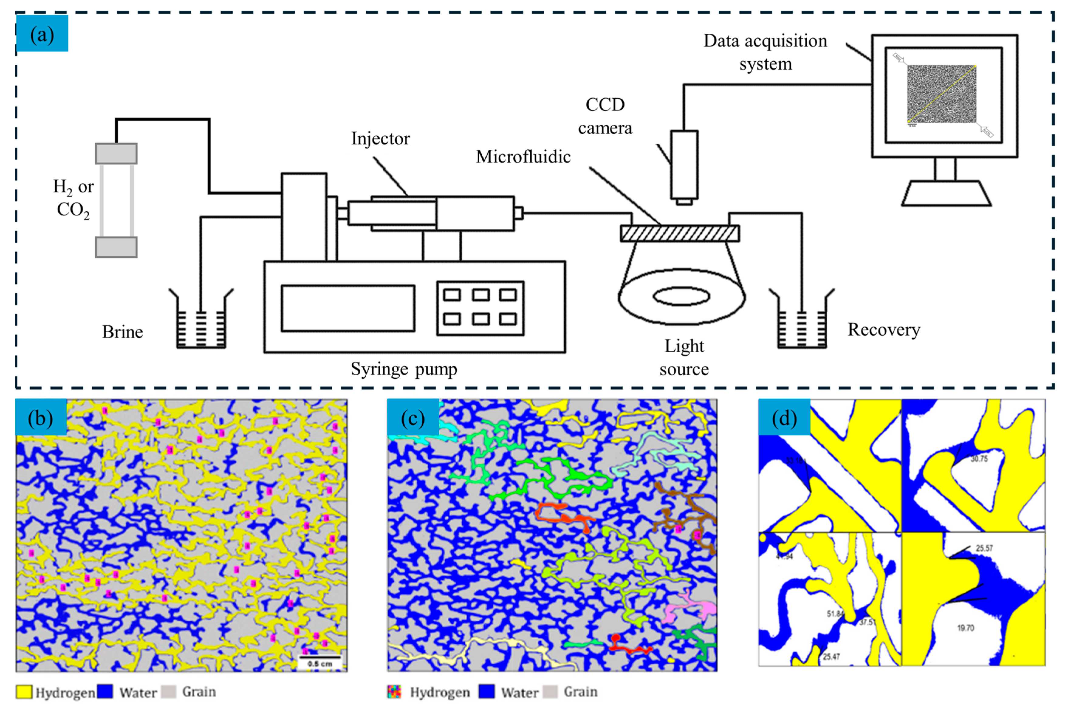
4.1. Microfluidic-Based Visualized Experiment
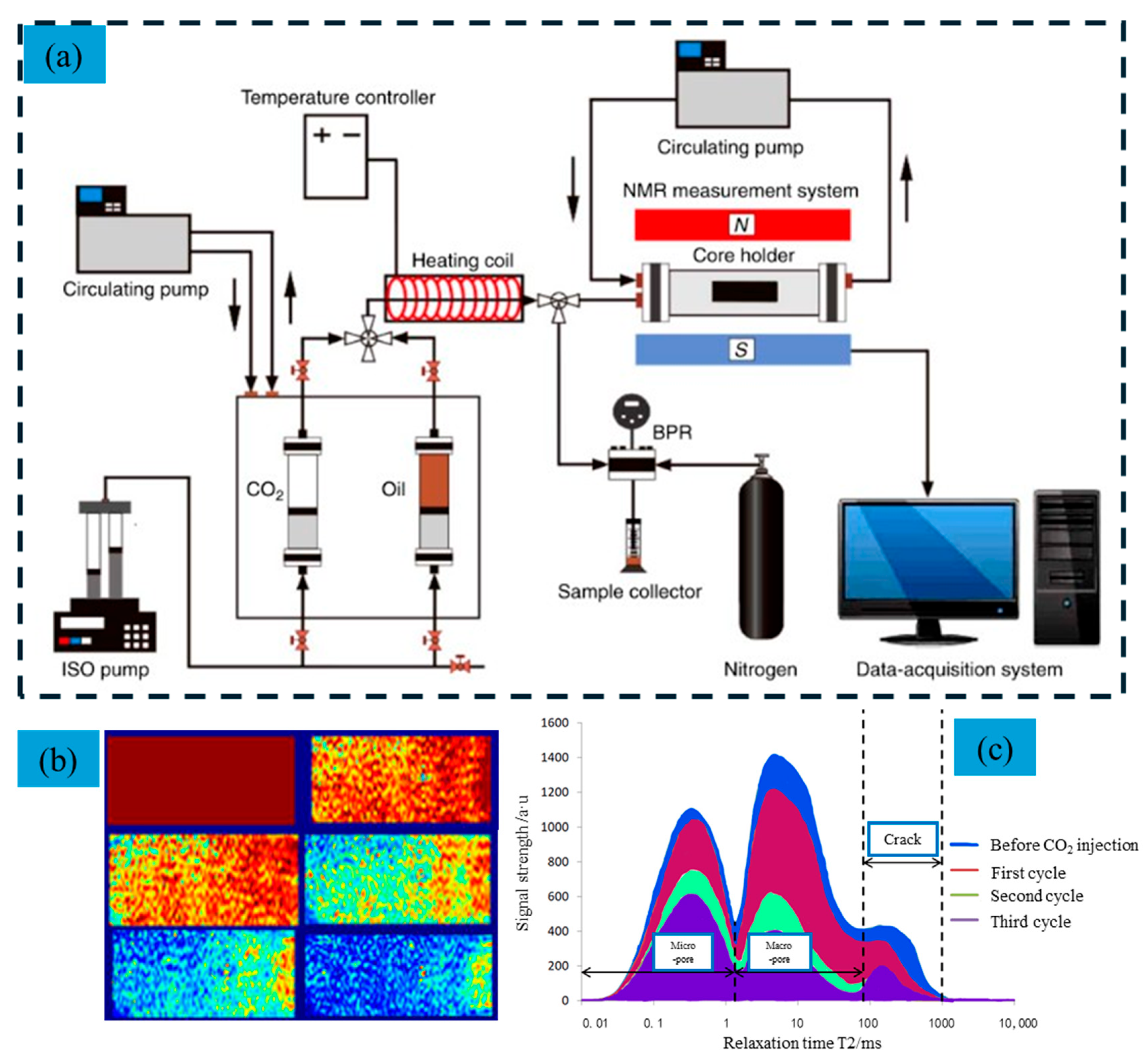
4.2. NMR-Based Visualized Experiment
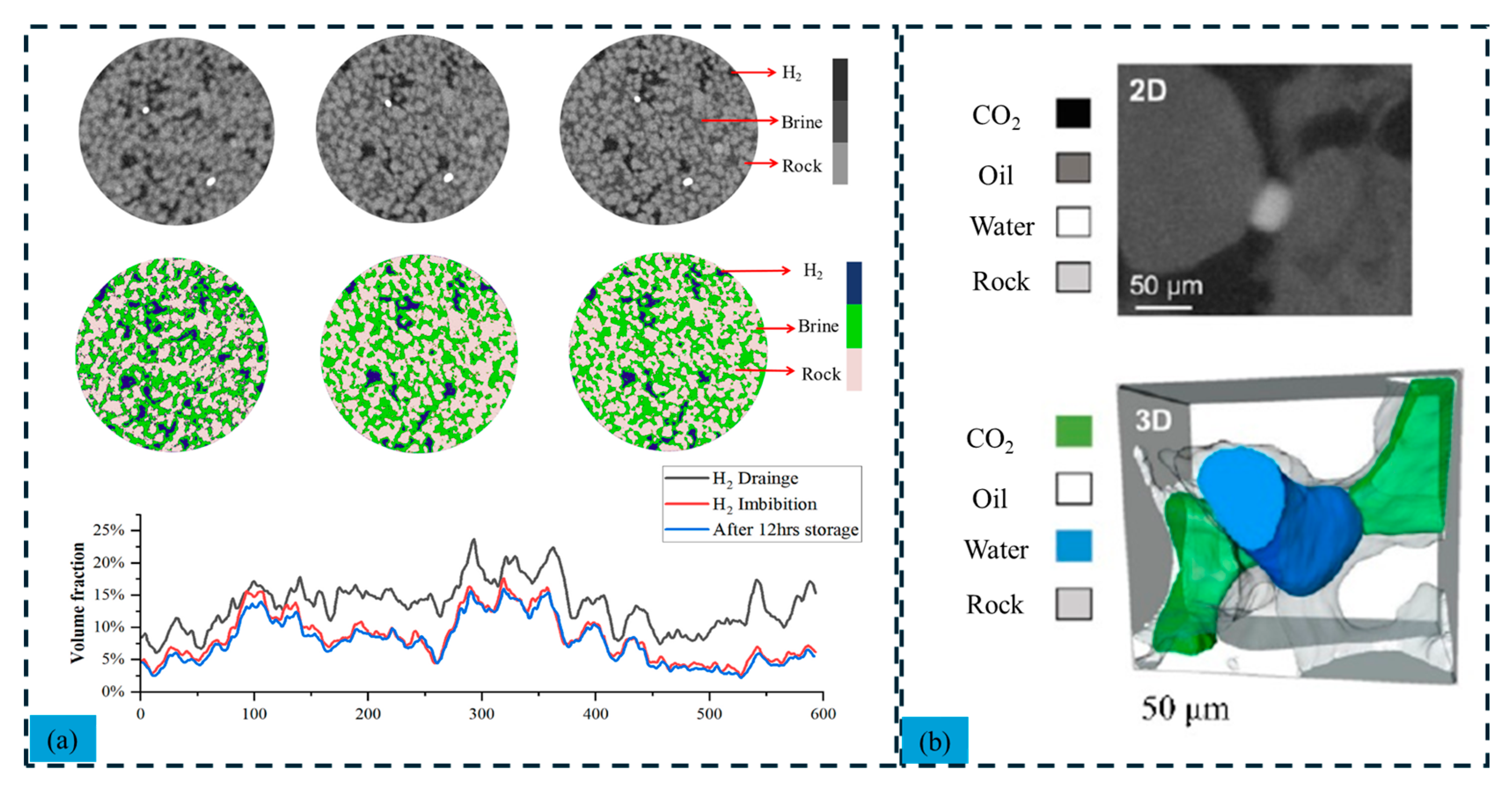
4.3. CT-Based Visualized Experiment
5. Comparison of Interface Tracking Methods in Pore-Scale Two-Phase Flow Simulation
6. Conclusions and Prospects
- (1)
- Accurate characterization of the pore structure in porous media is essential for predicting rock properties and fluid transport behavior. Various testing methods offer qualitative, semi-quantitative, or quantitative insights into the micro-pore structure, but each has limitations. A multi-technique integrated approach is crucial for a more comprehensive and precise analysis of rock properties and fluid flow within porous media.
- (2)
- Microscopic seepage experiments using visualization methods provide insights into fluid flow and pore-scale mechanics. Micro-seepage models quantify gas–water two-phase flow, optimizing conditions for improved production. These models aid in studying complex flow phenomena and, combined with 3D simulations, enhance understanding of reservoir seepage patterns and recovery factor research.
- (3)
- Recent advances in digital core technology and computational fluid dynamics have improved pore-scale two-phase flow simulations. Eulerian methods like VOF, level set, and phase field track phase interfaces but face challenges in mass conservation and accuracy. Integrating Eulerian and Lagrangian methods and enhancing computational efficiency will benefit applications in oil recovery, carbon sequestration, and hydrogen storage.
Author Contributions
Funding
Conflicts of Interest
References
- Zhao, Y.; Jiang, W.; Liu, Y. Current status and future prospects of hydrogen energy industry development. Saf. Health Environ. 2023, 23, 1–12. [Google Scholar]
- Bade, S.O.; Taiwo, K.; Ndulue, U.F.; Tomomewo, O.S.; Oni, B.A. A Review of Underground Hydrogen Storage Systems: Current Status, Modeling Approaches, Challenges, and Future Prospects. Int. J. Hydrogen Energy 2024, 80, 449–474. [Google Scholar] [CrossRef]
- Wang, L.; Jin, Z.; Lyu, Z.; Su, Y. Research progress and prospects of underground hydrogen storage. Earth Sci. 2024, 49, 2044–2057. [Google Scholar]
- Wei, X.; Shi, X.; Li, Y.; Li, P.; Ban, S.; Xue, T.; Zhu, S.; Liu, H.; Yang, C. Field experimental and theoretical research on creep shrinkage mechanism of ultra-deep energy storage salt cavern. Rock Mech. Rock Eng. 2024, 57, 287–305. [Google Scholar] [CrossRef]
- Li, X.; Huo, T.; Wei, K.; Yan, Z.; Zhu, L.; Xue, Q. The feasibility of hydrogen storage in aquifers: A molecular dynamics simulation. Fuel 2024, 367, 131469. [Google Scholar] [CrossRef]
- Zeng, L.; Sarmadivaleh, M.; Saeedi, A.; Chen, Y.; Zhong, Z.; Xie, Q. Storage integrity during underground hydrogen storage in depleted gas reservoirs. Earth-Sci. Rev. 2023, 247, 104625. [Google Scholar] [CrossRef]
- Bahrami, M.; Mahani, H.; Zivar, D.; Ayatollahi, S. Microfluidic investigation of pore-scale flow behavior and hysteresis in underground hydrogen storage in sandstones. J. Energy Storage 2024, 98, 112959. [Google Scholar] [CrossRef]
- Yao, H. Evaluation and Simulation of Dissolved CO2 Saline Aquifer Storage Sites; China University of Mining and Technology: Xuzhou, China, 2023. [Google Scholar]
- Lysyy, M.; Fernø, M.; Ersland, G. Seasonal hydrogen storage in a depleted oil and gas field. Int. J. Hydrogen Energy 2021, 46, 25160–25174. [Google Scholar] [CrossRef]
- Izadi Amiri, I.; Zivar, D.; Ayatollahi, S.; Mahani, H. The effect of gas solubility on the selection of cushion gas for underground hydrogen storage in aquifers. J. Energy Storage 2024, 80, 110264. [Google Scholar] [CrossRef]
- Leng, G.; Yan, W.; Chen, Z.; Li, Z.; Liu, B.; Deng, P.; Zhang, C.; Liu, W.; Qi, H. Technical challenges and opportunities of hydrogen storage: A comprehensive review on different types of underground storage. J. Energy Storage 2025, 114 Pt B, 115900. [Google Scholar] [CrossRef]
- Wang, J.; Wu, R.; Zhao, K.; Bai, B. Numerical simulation of underground hydrogen storage converted from a depleted low-permeability oil reservoir. Int. J. Hydrogen Energy 2024, 69, 1069–1083. [Google Scholar] [CrossRef]
- Al Homoud, R.; Daigle, H. Review and synthesis of experimental results on hydrogen wettability in different geological formations. Int. J. Hydrog. Energy 2024, 83, 115–123. [Google Scholar] [CrossRef]
- Zeng, L.; Vialle, S.; Ennis-King, J.; Esteban, L.; Sarmadivaleh, M.; Sarout, J.; Dautriat, J.; Giwelli, A.; Xie, Q. Role of geochemical reactions on caprock integrity during underground hydrogen storage. J. Energy Storage 2023, 65, 107414. [Google Scholar] [CrossRef]
- Bensing, J.P.; Misch, D.; Skerbisch, L.; Sachsenhofer, R.F. Hydrogen-induced calcite dissolution in Amaltheenton Formation claystones: Implications for underground hydrogen storage caprock integrity. Int. J. Hydrog. Energy 2022, 47, 30621–30626. [Google Scholar] [CrossRef]
- Thiyagarajan, S.R.; Emadi, H.; Hussain, A.; Patange, P.; Watson, M. A comprehensive review of the mechanisms and efficiency of underground hydrogen storage. J. Energy Storage 2022, 51, 104490. [Google Scholar] [CrossRef]
- Bhadariya, V.; Kaur, J.; Sapale, P.; Rasane, P.; Singh, J. Hydrogen storage in porous media: Understanding and mitigating microbial risks for a sustainable future. Int. J. Hydrog. Energy 2024, 67, 681–693. [Google Scholar] [CrossRef]
- Kalam, S.; Abu-Khamsin, S.A.; Kamal, M.S.; Abbasi, G.R.; Lashari, N.; Patil, S.; Abdurrahman, M. A Mini-Review on Underground Hydrogen Storage: Production to Field Studies. Fuels 2023, 37, 8128–8141. [Google Scholar] [CrossRef]
- Gbadamosi, A.O.; Muhammed, N.S.; Patil, S.; Al Shehri, D.; Haq, B.; Epelle, E.I.; Mahmoud, M.; Kamal, M.S. Underground hydrogen storage: A critical assessment of fluid-fluid and fluid-rock interactions. J. Energy Storage 2023, 72, 108473. [Google Scholar] [CrossRef]
- Juez-Larré, J.; Machado, C.G.; Groenenberg, R.M.; Belfroid, S.S.P.C.; Yousefi, S.H. A detailed comparative performance study of underground storage of natural gas and hydrogen in the Netherlands. Int. J. Hydrog. Energy 2023, 48, 28843–28868. [Google Scholar] [CrossRef]
- Luboń, K.; Tarkowski, R. Numerical simulation of hydrogen storage in the konary deep saline aquifer trap. Gospod. Surowcami Miner. 2023, 39, 103–124. [Google Scholar]
- Song, R.; Song, Y.; Liu, J.; Yang, C. Multiscale experimental and numerical study on hydrogen diffusivity in salt rocks and interlayers of salt cavern hydrogen storage. Int. J. Hydrog. Energy 2024, 79, 319–334. [Google Scholar] [CrossRef]
- Alfarge, D.; Khawwam, M.W.; Ibrahim, A.A.; Abbas, H.R.; Jawad, H.S.; Aljarah, A.M. Comparative review of geological formation characteristics for energy transition: Implications, potential, and challenges of hydrogen storage. Int. J. Green Energy 2025, 1–13. [Google Scholar] [CrossRef]
- Al-Yaseri, A.; Hussaini, S.R.; Fatah, A.; Al-Qasim, A.S.; Patil, P.D. Computerized tomography analysis of potential geochemical reactions of carbonate rocks during underground hydrogen storage. Fuel 2024, 361, 130680. [Google Scholar] [CrossRef]
- Xu, W.; Liang, L.; Gou, J.; Liu, X.; Xiong, J. Characterization of the pore structure of gravel rocks based on micro-CT scanning. Sci. Technol. Eng. 2025, 25, 999–1007. [Google Scholar]
- Hu, R.; Mu, N.; Wei, X.; Fan, G.Y.; Qiao, L.D. Characteristics of the tight oil reservoir in the 7th member of the Yanchang Formation, Ordos Basin, and the impact of carbonaceous fragments on reservoir physical properties. Miner. Rocks 2024, 1–17. [Google Scholar]
- Anovitz, L.M.; Cole, D.R. Characterization and analysis of porosity and pore structures. Rev. Mineral. Geochem. 2015, 80, 61–164. [Google Scholar] [CrossRef]
- Chunyan, W.; Zhuanying, Z.; Wenhou, L.; Ning, W.; Lin, W. Characterization of pore-throat characteristics in tight oil reservoirs by combined mercury injection method: A case study of the Chang 7 member of Yanchang Formation in Dingbian area, northern Shaanxi. Chin. J. Geol. 2023, 58, 710–722. [Google Scholar]
- He, J.; Liu, X.; Zhu, X.; Jiang, T.; He, H.; Zhou, L.; Liu, Q.; Zhu, Y.; Liu, L. Water-flooding characteristics of lithologic reservoir in Ordos basin. Sci. Rep. 2021, 11, 2503. [Google Scholar] [CrossRef]
- Langmuir, I. The constitution and fundamental properties of solids and liquids. II. Liquids. J. Am. Chem. Soc. 1917, 39, 1848–1906. [Google Scholar] [CrossRef]
- Brunauer, S.; Emmett, P.H.; Teller, E. Adsorption of gases in multimolecular layers. J. Am. Chem. Soc. 1938, 60, 309–319. [Google Scholar] [CrossRef]
- Yang, J.; Wu, W.; Qian, H. A review of the application of nuclear magnetic resonance in geotechnical engineering. Eng. Constr. 2019, 51, 26–31. [Google Scholar]
- Ramaswamy, V.; Hooker, J.W.; Withers, R.S.; Nast, R.E.; Edison, A.S.; Brey, W.W. Development of a 1H-13C dual-optimized NMR probe based on double-tuned high temperature superconducting resonators. IEEE Trans. Appl. Supercond. 2016, 26, 1–5. [Google Scholar] [CrossRef]
- Xie, R.; Wang, X.; Jin, G.; Guo, J. Simulation experiment design for evaluating reservoir pore structure based on nuclear magnetic resonance logging T2 spectrum. Exp. Sci. Technol. 2024, 22, 20–27. [Google Scholar]
- McCreesh, C.A.; Ehrlich, R.; Crabtree, S.J. Petrography and reservoir physics II: Relating thin section porosity to capillary pressure, the association between pore types and throat size. AAPG Bull. 1991, 75, 1563–1578. [Google Scholar]
- Liu, Y.; Xie, R.; Chai, X.; Li, G.Q.; Ge, X.M. Quantitative extraction technology of microscopic pore parameters in tight sandstone reservoirs based on casting thin sections. Henan Sci. 2017, 35, 134–138. [Google Scholar]
- Zhang, X.; Zhao, L.; Li, S.; Han, Z.G.; Xu, X.Q.; Wu, A.H. Calibration method of scanning electron microscope based on image processing. J. Test Meas. Technol. 2022, 36, 410–415. [Google Scholar]
- Wang, Y.; Jin, C.; Wang, L.; Wang, J.Q.; Jiang, Z.; Wang, Y.F. Research on shale pore segmentation method based on SEM image gray level. Rock Miner. Anal. 2016, 35, 595–602. [Google Scholar]
- Liu, Q.; Sun, M.; Sun, X.; Liu, B.; Ostadhassan, M.; Huang, W.; Chen, X.; Pan, Z. Pore network characterization of shale reservoirs through state-of-the-art X-ray computed tomography: A review. Gas Sci. Eng. 2023, 113, 204967. [Google Scholar] [CrossRef]
- Zhang, C.; Jia, S.; Wang, Y.L.; Zhao, Y.X.; Cheng, Y.H.; Wang, F.T. Research progress on CT scanning reconstruction of coal samples: Principles, methods, and applications. J. China Coal Soc. 2024, 1–20. [Google Scholar]
- Wang, J.; Yang, Y.; Cai, S.; Yao, J.; Xie, Q. Pore-scale modelling on hydrogen transport in porous media: Implications for hydrogen storage in saline aquifers. Int. J. Hydrogen Energy 2023, 48, 13922–13933. [Google Scholar] [CrossRef]
- Zhang, Y.; Kogure, T.; Nishizawa, O.; Xue, Z. Different flow behavior between 1-to-1 displacement and co-injection of CO2 and brine in Berea sandstone: Insights from laboratory experiments with X-ray CT imaging. Int. J. Greenh. Gas Control 2017, 66, 76–84. [Google Scholar] [CrossRef]
- Wang, J.; Liu, H.; Zhang, J.; Xie, J. Lost gas mechanism and quantitative characterization during injection and production of water-flooded sandstone underground gas storage. Energies 2018, 11, 272. [Google Scholar] [CrossRef]
- Sun, H.; Yao, J.; Cao, Y.-C.; Fan, D.-Y.; Zhang, L. Characterization of gas transport behaviors in shale gas and tight gas reservoirs by digital rock analysis. Int. J. Heat Mass Transf. 2017, 104, 227–239. [Google Scholar] [CrossRef]
- Guo, Z.; Zheng, C. Principle and application of Lattice Boltzmann Method; Science Press: Beijing, China, 2008. [Google Scholar]
- Zhao, Y.Z. Numerical Simulation of Flow-Solid Coupling in Sand Production Fracturing Capacity of Loose Sandstone Reservoirs; China University of Petroleum: Beijing, China, 2008. [Google Scholar]
- Song, H.; Guo, H.; Wang, Y.; Lao, J.; Zhu, H.; Tang, L.; Liu, X. A novel hybrid energy system for hydrogen production and storage in a depleted oil reservoir. Int. J. Hydrogen Energy 2021, 46, 18020–18031. [Google Scholar] [CrossRef]
- Berg, S.; Oedai, S.; Ott, H. Displacement and mass transfer between saturated and unsaturated CO2–brine systems in sandstone. Int. J. Greenh. Gas Control 2013, 12, 478–492. [Google Scholar] [CrossRef]
- Chen, H.; Guo, H.; Ye, F.; Ma, C.F. Improving two-phase mass transportation under Non-Darcy flow effect in orientated-type flow channels of proton exchange membrane fuel cells. Int. J. Hydrogen Energy 2021, 46, 21600–21618. [Google Scholar] [CrossRef]
- Kogure, T.; Nishizawa, O.; Chiyonobu, S.; Yazaki, Y.; Shibatani, S.; Xue, Z. Effect of sub-core scale heterogeneity on relative permeability curves of porous sandstone in a water-supercritical CO2 system. Energy Procedia 2013, 37, 4491–4498. [Google Scholar] [CrossRef]
- Xiang, Z.; Zhen, R.; Xu, Y.; Wang, S.; Ao, X.; Chen, Z.; Hu, J. A numerical pressure transient model of fractured well with complex fractures of tight gas reservoirs considering gas-water two-phase by EDFM. Geoenergy Sci. Eng. 2023, 231 Pt A, 212286. [Google Scholar] [CrossRef]
- Yan, H. Study on the Wettability Effect of Two-Phase Seepage at the Pore Scale of Porous Media Based on Real Microstructure; Hebei University: Baoding, China, 2024. [Google Scholar]
- Xu, K.; Liang, T.; Zhu, P.; Qi, P.; Lu, J.; Huh, C.; Balhoff, M. A 2.5-D glass micromodel for investigation of multi-phase flow in porous media. Lab A Chip 2017, 17, 640–646. [Google Scholar] [CrossRef]
- Gunda, N.S.K.; Bera, B.; Karadimitriou, N.K.; Mitra, S.K.; Hassanizadeh, S.M. Reservoir-on-a-chip (ROC): A new paradigm in reservoir engineering. Lab A Chip 2011, 11, 3785–3792. [Google Scholar] [CrossRef]
- Auset, M.; Keller, A.A. Pore-scale processes that control dispersion of colloids in saturated porous media. Water Resour. Res. 2004, 40, W03503. [Google Scholar] [CrossRef]
- Mohammadi, S.; Maghzi, A.; Ghazanfari, M.H.; Masihi, M.; Mohebbi, A.; Kharrat, R. On the control of glass micro-model characteristics developed by laser technology. Energy Sources Part A 2013, 35, 193–201. [Google Scholar] [CrossRef]
- Park, D.S.; Bou-Mikael, S.; King, S.; Thompson, K.E.; Willson, C.S.; Nikitopoulos, D.E. Design and fabrication of rock-based micromodel. ASME Int. Mech. Eng. Congr. Expo. Proc. (IMECE) 2012, 9, 709–715. [Google Scholar]
- Jansen, J.; Melchels, F.P.; Grijpma, D.W.; Feijen, J. Fumaric acid monoethyl ester-functionalized poly(D, L-lactide)/N-vinyl-2-pyrrolidone resins for the preparation of tissue engineering scaffolds by stereolithography. Biomacromolecules 2009, 10, 214–220. [Google Scholar] [CrossRef]
- Dehury, R.; Chowdhury, S.; Sangwai, J.S. Dynamics of hydrogen storage in subsurface saline aquifers: A computational and experimental pore-scale displacement study. Int. J. Hydrogen Energy 2024, 69, 817–836. [Google Scholar] [CrossRef]
- Yang, G.; Feng, K.; Zhang, H. Pressure drop and bubble length prediction for gas-non-Newtonian fluid two-phase flow in a curved microchannel. Chem. Eng. Res. Des. 2023, 197, 405–418. [Google Scholar] [CrossRef]
- Guo, R.; Ershadnia, R.; Wang, H.; Hosseini, S.A.; Zhao, Q. Microfluidic experiments on hydrogen behavior in heterogeneous rocks during underground hydrogen storage in saline aquifers. Fuel 2025, 391, 134731. [Google Scholar] [CrossRef]
- Sun, J.; Yang, Z.; Liu, X.W.; Xiong, S.C. A Review of the Application of Nuclear Magnetic Resonance Technology in Wettability Evaluation of Oil and Gas Reservoirs. Sci. Technol. Rev. 2012, 30, 65–71. [Google Scholar]
- Liu, G.; Xie, S.; Tian, W.; Wang, J.; Li, S.; Wang, Y.; Yang, D. Effect of pore-throat structure on gas-water seepage behaviour in a tight sandstone gas reservoir. Fuel 2022, 310 Pt B, 121901. [Google Scholar] [CrossRef]
- Fannir, J.; Panfilova, I.; Leclerc, S.; Stemmelen, D. Studying of parameters of two-phase displacement in porous media with MRI technique. Mech. Ind. 2020, 21, 524. [Google Scholar] [CrossRef]
- Williams, J.L.A.; Taylor, D.G.; Maddinelli, G.; Enwere, P.; Archer, J.S. Visualisation of fluid displacement in rock cores by NMR imaging. Magn. Reson. Imaging 1991, 9, 767–773. [Google Scholar] [CrossRef]
- Jiang, L. Experimental Study on Multiphase Flow in Porous Media Using Nuclear Magnetic Resonance Imaging; Dalian University of Technology: Dalian, China, 2010. [Google Scholar]
- Ren, G. Experimental study on gas-water two-phase flow in tight sandstone gas reservoirs using online nuclear magnetic resonance. J. China Univ. Pet. 2021, 35, 46–49. [Google Scholar]
- Cheng, Y. Visualization Study of Fluid Distribution in Cores Based on Low-Field Nuclear Magnetic Resonance Imaging Technology; Shanghai University: Shanghai, China, 2014. [Google Scholar]
- Goodarzi, S.; Zhang, G.; Bijeljic, B.; Blunt, M.J. Ostwald ripening leads to less hysteresis during hydrogen injection and withdrawal: A pore-scale imaging study. Int. J. Hydrogen Energy 2025, 114, 475–485. [Google Scholar] [CrossRef]
- Blunt, M.J.; Bijeljic, B.; Dong, H.; Gharbi, O.; Iglauer, S.; Mostaghimi, P.; Paluszny, A.; Pentland, C. Pore-scale imaging and modelling. Adv. Water Resour. 2013, 51, 197–216. [Google Scholar] [CrossRef]
- Aftab, A.; Hassanpouryouzband, A.; Xie, Q.; Machuca, L.L.; Sarmadivaleh, M. Toward a fundamental understanding of geological hydrogen storage. Ind. Eng. Chem. Res. 2022, 61, 3233–3253. [Google Scholar] [CrossRef]
- Guo, B. Study on Microscopic Characteristics of Hudson East River Sandstone Based on CT Scanning; Chengdu University of Technology: Chengdu, China, 2022. [Google Scholar]
- Khandoozi, S.; Li, P.; Ershadnia, R.; Dai, Z.; Zhang, Z.; Stauffer, P.H.; Mehana, M.; Cole, D.R.; Soltanian, M.R. An integrated approach for optimizing geological hydrogen storage. Appl. Energy 2025, 381, 125182. [Google Scholar] [CrossRef]
- Zhao, Q.; Guo, R.; Jha, N.K.; Sarmadivaleh, M.; Lebedev, M.; Al-Yaseri, A.; McClure, J.; Chen, C. Using X-ray computed tomography and pore-scale numerical modeling to study the role of heterogeneous rock surface wettability on hydrogen-brine two-phase flow in underground hydrogen storage. Fuel 2024, 366, 131414. [Google Scholar] [CrossRef]
- Song, R.; Feng, D.; Hui, G.; Liu, J.; Yang, C. Visualized experiments on the hydrogen transports and bubble ripening mechanism in porous reservoir of underground hydrogen storage. Int. J. Hydrogen Energy 2025, 105, 326–344. [Google Scholar] [CrossRef]
- Liu, Q.; Li, J.; Liang, B.; Sun, W.; Liu, J.; Lei, Y. Microscopic flow of CO2 in complex pore structures: A Recent 10-Year review. Sustainability 2023, 15, 12959. [Google Scholar] [CrossRef]
- Huang, L. Study on the Coupling Flow Laws and Interface Conditions of Two-Phase Seepage and Free Flow; China University of Petroleum (East China): Qingdao, China, 2021. [Google Scholar]
- Peng, J.; Xia, B.; Lu, Y.; Wang, L.; Song, R. Pore-scale numerical investigation on the capillary trapping of hydrogen in natural sandstone under in-situ wettability condition: Implications for underground hydrogen storage in aquifers. Int. J. Hydrogen Energy 2025, 113, 509–522. [Google Scholar] [CrossRef]
- Liu, Y.; Yang, D.; Cai, Y. Numerical study on hydrogen-water flow in the microfluidic model for underground hydrogen storage in aquifers. Int. J. Hydrogen Energy 2025, 113, 406–419. [Google Scholar] [CrossRef]
- Safari, A.; Esfandyari, H.; Sugai, Y.; Haghighi, M.; Zeinijahromi, A.; Sarmadivaleh, M.; Masoumi, H. Computational fluid dynamics modeling of rock–liquid–H2 contact angles: Implications for underground hydrogen storage. J. Energy Storage 2024, 81, 110475. [Google Scholar] [CrossRef]
- Davoodi, S.; Al-Shargabi, M.; Wood, D.A.; Longe, P.O.; Mehrad, M.; Rukavishnikov, V.S. Underground hydrogen storage: A review of technological developments, challenges, and opportunities. Appl. Energy 2025, 381, 125172. [Google Scholar] [CrossRef]
- Zhu, Q.; Yang, Y.; Zhang, X.; Wang, S.; Yang, J.; Zhang, J. Pore-Scale Simulation of Gas and Water Two-Phase Flow in Rough-Walled Fractures Using the Volume of Fluid Method. Energies 2022, 15, 9382. [Google Scholar] [CrossRef]
- Wang, W.; Sun, Y.; Wang, B.; Dong, M.; Chen, Y. CFD-Based Erosion and Corrosion Modeling of a Pipeline with CO2-Containing Gas–Water Two-Phase Flow. Energies 2022, 15, 1694. [Google Scholar] [CrossRef]
- Ling, K.; Zhang, S.; Wu, P.-Z.; Yang, S.-Y.; Tao, W.-Q. A coupled volume-of-fluid and level-set method (VOSET) for capturing interface of two-phase flows in arbitrary polygon grid. Int. J. Heat. Mass. Transf. 2019, 143, 118565. [Google Scholar] [CrossRef]
- Cai, P.; Que, Y.; Jiang, Z.; Li, X. 3D quantitative characterization and flow simulation of macropores in granite residual soil based on CT scanning. Sci. China Technol. Sci. 2022, 52, 1065–1082. [Google Scholar]


| Citation | Main Concerns | Research Directions |
|---|---|---|
| Rana et al., 2024 [13]; Leng et al., 2025 [11] | Suitable reservoir types | Screening and evaluation of geological structures for hydrogen storage |
| Zeng et al., 2023 [14]; Bensing et al., 2022 [15] | Geological requirements | |
| Thiyagarajan et al., 2022 [16]; Bhadariya et al., 2024 [17] | Microbial activity | Interactions between hydrogen and subsurface environments |
| Kalam et al., 2023 [18]; Gbadamosi et al., 2023 [19] | Rock–fluid reactions | |
| Juez-Larre et al., 2023 [20]; Lubon et al., 2023 [21] | Injection and withdrawal processes | Engineering technologies and operational optimization |
| Song et al., 2024 [22]; Alfarge et al., 2025 [23] | Safety and risk management |
| Numerical Methods for Multiphase Flow | Formula | Scope/Characteristics |
|---|---|---|
| VOF Method Zhu et al., 2023 [82]; Wang et al., 2022 [83] | where p represents the pressure; g represents the acceleration due to gravity; ρ represents the density; denotes the velocity vector of the fluid; μ denotes the dynamic viscosity of the fluid; describes the Laplace pressure acting at the interface; The volume fraction of the water phase is aw. α is represents flow volume; uc is represents compress velocity. | It is applicable to immiscible multiphase flow interfaces with very distinct phase boundaries. However, the VOF (volume of fluid) function is a discontinuous function at the phase interface, leading to poor continuity. |
| Phase Field Method (Using the Cahn-Hilliard equation) Safari et al., 2024 [80] | where φ represents the phase field variable in different regions, which varies between −1 and 1, ψ represents the chemical potential, also known as the phase field auxiliary variable, ε is the control parameter for the thickness of the two-phase interface, and γ denotes the migration regulation parameter; u is the velocity. | It is suitable for studying the wettability and two-phase seepage mechanisms in porous structures with complex pore throat geometry, as it can accurately capture the interface; however, it is unable to maintain mass conservation. |
| Level Set Liu et al., 2025 [79] | where ∂φ/∂t represents the accumulation term with respect to time; u∙∇φ represents the advection term, where u denotes the velocity; when the fluid is compressible, the velocity divergence is not zero, in which case the advection term is ∇(uφ); γ is the reinitialization parameter; ε is the interface thickness control parameter. | It is suitable for tracking free interfaces in complex fluids, with good continuity at the phase interface, but it cannot quantitatively satisfy mass conservation. |
| VOSET Equation Ling et al., 2019 [84] | where ф is the symbol for the distance function; p is pressure, in Pa; p(ф) and u(ф) refer to the gas–liquid mixture density and the mixture viscosity; u is the velocity; g represents the acceleration due to gravity. | Coupling the VOF and LS methods, and using a geometric interface front construction approach to build the phase interface. |
| PNM Method Cai et al., 2022 [85] | where j refers to all pores connected to pore i; qij is the flow rate between pore i and pore j; gij is the conductivity of the throat connecting pore i and pore j; Pi and Pj are the pressures at pore i and pore j; k is the permeability of the pore network model; p is the applied pressure gradient between the inlet and outlet of the model; L is the length of the model in the flow direction. | Two-phase flow processes can be simulated by constructing models that incorporate parameters such as the distribution, size, and aspect ratio of pores and throats. Analyzing how these parameters evolve during the flow process can predict flow patterns in porous media. |
Disclaimer/Publisher’s Note: The statements, opinions and data contained in all publications are solely those of the individual author(s) and contributor(s) and not of MDPI and/or the editor(s). MDPI and/or the editor(s) disclaim responsibility for any injury to people or property resulting from any ideas, methods, instructions or products referred to in the content. |
© 2025 by the authors. Licensee MDPI, Basel, Switzerland. This article is an open access article distributed under the terms and conditions of the Creative Commons Attribution (CC BY) license (https://creativecommons.org/licenses/by/4.0/).
Share and Cite
He, X.; Wang, Y.; Zheng, Y.; Zhang, W.; Dai, Y.; Zou, H. Pore-Scale Gas–Water Two-Phase Flow Mechanisms for Underground Hydrogen Storage: A Mini Review of Theory, Experiment, and Simulation. Appl. Sci. 2025, 15, 5657. https://doi.org/10.3390/app15105657
He X, Wang Y, Zheng Y, Zhang W, Dai Y, Zou H. Pore-Scale Gas–Water Two-Phase Flow Mechanisms for Underground Hydrogen Storage: A Mini Review of Theory, Experiment, and Simulation. Applied Sciences. 2025; 15(10):5657. https://doi.org/10.3390/app15105657
Chicago/Turabian StyleHe, Xiao, Yao Wang, Yuanshu Zheng, Wenjie Zhang, Yonglin Dai, and Hao Zou. 2025. "Pore-Scale Gas–Water Two-Phase Flow Mechanisms for Underground Hydrogen Storage: A Mini Review of Theory, Experiment, and Simulation" Applied Sciences 15, no. 10: 5657. https://doi.org/10.3390/app15105657
APA StyleHe, X., Wang, Y., Zheng, Y., Zhang, W., Dai, Y., & Zou, H. (2025). Pore-Scale Gas–Water Two-Phase Flow Mechanisms for Underground Hydrogen Storage: A Mini Review of Theory, Experiment, and Simulation. Applied Sciences, 15(10), 5657. https://doi.org/10.3390/app15105657