1. Introduction
Reinforced concrete (RC) constructions continue to be a predominant selection in contemporary building practices owing to the advantageous combination of concrete’s remarkable compressive strength along with the enhanced tensile characteristics conferred by steel reinforcement. In recent years, engineers have intensified their initiatives aimed at accelerating construction schedules, improving material integrity, and optimizing cost efficiency. In pursuit of these objectives, precast reinforced concrete (PRC) systems have surfaced as a significant alternative, delivering centralized quality assurance through off-site fabrication, which subsequently streamlines the on-site assembly process upon the delivery of components. Consequently, precast methodologies have gained widespread acceptance, not only for the erection of extensive industrial structures, such as manufacturing facilities and storage units, but also for the construction of multi-story residential and commercial complexes, where the speed and dependability of construction are of paramount importance.
The evolution of precast technology throughout history has been primarily influenced by the objective of minimizing on-site labor and formwork activities while ensuring consistent quality and uniformity [
1]. Conventional cast-in-place concrete construction typically requires significant labor, extensive formwork setup, prolonged curing durations, and is vulnerable to fluctuations in environmental conditions during the curing process. Conversely, precast components can be manufactured in regulated settings, resulting in superior material strengths and more precise dimensional tolerances. Numerous developed countries have long acknowledged these benefits, culminating in the off-site production of comprehensive building systems, encompassing beams, columns, and façade components. Although precast construction offers advantages in terms of cost efficiency, rapidity, and material integrity, apprehensions persist regarding the ductility and seismic resilience of precast frameworks, especially at their junctions. Recent research has highlighted the seismic vulnerability of precast load-bearing wall systems. Riberio et al. [
2] performed a probabilistic seismic evaluation of long-span precast industrial structures with wall systems, revealing that inadequacies in panel continuity and anchoring details might significantly affect the overall collapse probability. Their results highlight the need for comprehensive enhancements in several components of the PRC, beyond only the frame parts.
Beam–column connections in PRC frameworks fundamentally differ from those in cast-in-place constructions. In a structure that has been cast monolithically, the continuity of reinforcement and concrete facilitates a relatively uninterrupted transfer of bending moments, shear forces, and axial loads throughout the beam–column junction. When exposed to seismic activities, this continuity aids in distributing stresses in a more consistent and ductile manner, although it remains susceptible to potential failure if not designed according to contemporary seismic criteria. In precast construction, each structural component is produced independently, necessitating the re-establishment of continuity at beam–column connections on-site. A variety of connection types, such as wet joints, mechanical couplers, post-tensioning, and hybrid steel–concrete interfaces, have been investigated to simulate the performance of monolithic frameworks. The difficulty arises because any inadequacy or flaw at a precast connection could jeopardize the integrity of the entire lateral load-resisting system [
3].
Beam–column connections play a crucial role in precast skeletal frames, serving as the most significant type of connection within this structural system. Typical beam–column connection types are presented in
Figure 1. The engineering community often perceives these connections as challenging to specify, design, and construct, particularly when they are concealed within the beam itself. These connections fundamentally influence the behavior of the beam under flexural loads by regulating deflection and the functional performance of structural floor zones. Additionally, they impact the stability of the frame and the buckling resistance of the column. As shown in
Figure 1, the vertical component may be continuous with horizontal elements affixed to it (Type I), or the vertical component may be discontinuous while the horizontal elements may exhibit structural continuity or be distinct across the interface (Type II).
Type I connections can be further classified into two distinct categories: concealed connections (A), of which there is a considerable variety, and apparent connections (B), which encompass shallow and deep corbels or nibs. Type II connections are also divided into two categories: the ends of beams that are simply supported and dowelled at the column head (C) and continuous beams that are supported and dowelled at the column head (D). A beam–beam half joint is constructed at a distance from the face of the column, or, alternatively, the beam may project as a cantilevered balcony. For further information, the reader is directed to Elliott [
4].
Seismic events impose significant challenges on structural connections by applying cyclic lateral forces that induce alternating tensile and compressive stress within beams and columns. In a cast-in-place structure, when a beam is compelled to form plastic hinges adjacent to the column faces, the inelastic deformation capacity is predominantly influenced by the ductility of the longitudinal reinforcement and the confinement of the concrete in the hinge area. In contrast, within a precast framework, the formation of plastic hinges may occur at unintended locations, often contingent upon the specifics of the connector design, the lengths of anchorage, and the degree to which the assembled components mimic monolithic behavior. Historical seismic events have documented suboptimal performance of precast connections, most notably during the 1994 Northridge earthquake, the 1995 Kobe earthquake, 1999 Izmit earthquake, 2009 L’Aquila earthquake [
5,
6,
7,
8,
9,
10], and more recently during the 2023 Kahramanmaraş earthquake in Turkey [
11]. Post-disaster field evaluations have consistently highlighted deficiencies in connection details, inadequate ductility of the connection components, and the prevalence of brittle failure mechanisms within the joint region.
The susceptibility of beam–column junctions highlights the imperative for design methodologies that concentrate on averting undesirable brittle failures at the interfaces. A multitude of investigations has examined the failure characteristics of precast beam–column connections subjected to seismic forces. Notable shortcomings encompass slippage of reinforcement attributable to inadequate anchorage, premature shear failure of joints, and concrete crushing or spalling at the column interface, where unintentional plastic hinge formation frequently occurs. Pang and Li [
12] noted that the integration of L-shaped steel plates at the beam–column intersection significantly alleviates initial damage, thereby enhancing seismic resilience. Cao and Yang [
13] determined that the seams of connections in monolithic precast joints play a critical role in the progression of damage, highlighting the necessity for refined joint detailing. Guo et al. [
14] asserted that corrosion in grouting sleeve connections compromises the seismic performance of precast joints, thus emphasizing the vital importance of designing durable joints. These observations corroborate that beam–column connections are among the most susceptible areas in precast reinforced concrete systems and further validate the requirement for mechanisms such as the ACPH, which are engineered to concentrate damage within a sacrificial component while safeguarding the adjacent structural elements.
Initial strategies are aimed at enhancing the ductility of precast connections adopting fully grouted sleeves that interconnect reinforcing bars across the joint or utilize welded plates that secured beam bars to the column surface. Although these techniques can produce resilient connections when meticulously detailed, they may not consistently withstand the inelastic demands imposed by intense seismic activity without incurring substantial damage that jeopardizes the potential for reuse or repair. Indeed, the concept of damage localization has garnered heightened significance: should the plastic hinge develop in a predetermined area that is amenable to repair or replacement, the remaining structural elements may largely remain undamaged, thereby facilitating and accelerating post-seismic repairs. The idea of a replaceable plastic hinge exemplifies this damage-mitigation strategy. By confining inelastic behavior to a specifically designed connector, the primary beam and column elements can stay within an elastic range, even amidst severe seismic shaking.
The underlying justification for prioritizing a replaceable plastic hinge over a monolithic emulation is in part driven by practical requirements for resilient structures that can be swiftly reinstated following seismic events. Facilities located in industrial zones or essential infrastructures such as hospitals and emergency shelters typically cannot endure protracted periods of inactivity for repairs. Conventional restoration methods for compromised beam ends in a monolithic configuration may necessitate partial demolition, shoring, re-bar splicing, and on-site re-casting, all of which are time-intensive processes. Alternatively, the utilization of a specially engineered steel device that can be bolted or otherwise conveniently affixed and detached at the end of the beam allows for the concentration of damage from repetitive deformations within that device, which can be replaced within a timeframe of hours or days. This concept lies at the foundation of the artificially controllable plastic hinge (ACPH). Essentially, the ACPH is based on a weak-joint/strong-component philosophy, ensuring that the replaceable steel element yields or fails prior to the beam or column, thereby preserving the integrity of the primary structural components. Engineers gain an advantage as this device can be designed and detailed to meet both strength and deformation capacity criteria while also facilitating controlled energy dissipation.
Another significant dimension of the context pertains to the obstacles associated with the analytical and experimental verification of these principles. The intricacies inherent in precast connections necessitate sophisticated nonlinear analyses, including finite-element modeling incorporating damage plasticity for concrete or enhanced joint macro-models that effectively encompass slip, localized strain concentrations, and strain-rate phenomena [
15]. Numerous building regulations, such as the American ACI Code (ACI 318-R) [
16] or the Turkish Building Earthquake Code (TBEC 2018) [
17], have initiated the incorporation of clauses addressing precast joints but frequently stipulate that any innovative connector must exhibit performance that is equal to or surpasses that of a corresponding monolithic joint. Consequently, the responsibility rests on researchers and practitioners to undertake both extensive experimental studies and high-fidelity numerical simulations capable of validating the potential for stable hysteretic behavior, sufficient energy dissipation, and re-centering if necessary. Over the past decade, the shift towards performance-based earthquake engineering has increasingly emphasized the necessity for specialized components that can be repaired or substituted following a seismic event, thus minimizing downtime and enhancing the post-event operational capability of the structure.
The principal aim of this investigation is to enhance the comprehension of how a novel replaceable plastic hinge mechanism, referred to in this discourse as the ACPH, can be assimilated into the beam-to-column junctions of PRC frameworks. The intention is to examine an innovative design that confines seismic damage within a meticulously calibrated steel hinge assembly, thereby enabling the overarching structural components, specifically the beams and columns, to retain significant elasticity even amid intense seismic activity. By obstructing the emergence of conventional plastic hinges within the beams themselves, it becomes plausible to either completely safeguard or substantially mitigate damage in primary structural elements, culminating in a structure that can be expediently repaired and restored to normal operations after a substantial earthquake.
Recent trends in seismic engineering prioritize resilience-oriented design, which not only meets structural performance criteria such as strength, ductility, and energy dissipation but also extends beyond life safety to include post-earthquake functionality, rapid recovery, and minimized downtime. Resilience, as articulated in modern frameworks, emphasizes systems that are not only damage-resistant but also swiftly repairable with minimum intervention, especially in critical infrastructure and industrial contexts. Shen et al. [
18] underscore that the incorporation of resilience measures in RC systems must include both structural integrity and lifecycle continuation after seismic occurrences. In this context, the ACPH system, originally proposed by Yuan et al. [
15], provides a strong alternative to traditional detailing by localizing inelastic behavior in easily replaceable steel plates, thereby minimizing long-term maintenance requirements and improving the structure’s ability to return to function after significant earthquakes. This research enhances the existing literature focused on integrating seismic safety with structural resilience.
The uniqueness of this research is in its system-level implementation and validation of the ACPH inside full-scale precast concrete frameworks, with multi-bay and multi-story configurations built using inferior materials. This research expands the analysis beyond prior work that focused only on subassembly testing to include the frame-level seismic response under actual ground motion input. The ACPH structure utilizes standard steel grades, bolted interchangeability, and modular assembly, attributes that enhance practical viability for extensive field use in retrofit or new construction scenarios.
2. Significance of Research
The widespread integration of PRC systems, especially in scenarios where conventional concrete and steel fall short of contemporary strength standards, underscores an urgent requirement for connections that enhance both seismic resilience and reparability. The deficiencies in material characteristics result in heightened brittleness in standard precast beam–column joints, leading to a decrease in ductility and considerable damage during moderate to severe seismic incidents. In response to this challenge, the present research conducts an in-depth evaluation of existing precast connection methodologies, complemented by an innovative finite-element modeling initiative designed to assess the efficacy of a novel device called the ACPH.
A core focus of this investigation is to ascertain whether the ACPH can meet crucial seismic performance criteria, particularly adequate ductility, effective hysteretic behavior, and dependable protection for beams and columns, when employed within structures built from materials that do not meet established strength benchmarks. To this end, four distinct precast frame configurations are scrutinized, varying in the number of bays and stories. This systematic approach allows for a detailed analysis of the ACPH’s influence on base shear demands, fundamental periods, localized damage patterns, and potential failure mechanisms. The research emphasizes the performance of PRC components that are substandard relative to prevailing seismic codes.
Furthermore, a significant objective is to juxtapose the ACPH against conventional precast joints designed to emulate the behavior of monolithic cast-in-place structures, often labeled as wet connections. The intention is to evaluate whether this innovative hinge can achieve safety levels that equal or exceed those of established techniques, while also presenting notable advantages in terms of post-earthquake reparability. As performance-oriented seismic standards increasingly necessitate concise documentation of equivalent or superior performance for new connection systems, this study enhances its numerical assessments with calibrations derived from prior subassembly testing. By utilizing real seismic data, exemplified by the Mw 7.7 Kahramanmaraş earthquake, the research evaluates the dynamic response of the ACPH during intense seismic occurrences. Collectively, these endeavors aim to elucidate the potential of a replaceable plastic hinge to remedy prevalent deficiencies in precast frameworks characterized by inadequate material properties, ultimately proposing a practical avenue for the development of more resilient and easily recoverable structural systems.
3. State of the Art
The investigation into the enhancement of seismic performance in precast beam–column connections has yielded a variety of innovative methodologies. A multitude of studies have concentrated on the challenges associated with connection zones in prefabricated structures. For instance, Nzabonimpa et al. [
19] devised a beam–column connection model that incorporates bolts and steel plates, revealing minimal cracking at the joint, despite the prevalence of withdrawal stresses on the bolts at the beam’s extremity. Hu et al. [
20] introduced an energy dissipation mechanism utilizing a short H-shaped steel element with a web opening, which demonstrated significant capabilities for energy dissipation, rotational capacity, and ductility, thereby outperforming monolithic joints in performance metrics. Li et al. [
21] focused on creating a beam-to-column steel joint with low-yield-point steel for energy dissipation, effectively regulating the plastic hinge locations through energy dissipation segments. Their experimental findings illustrated improved hysteretic behavior and enhanced ductility as compared to traditional monolithic connections. Zhang et al. [
22] presented a precast hybrid steel fiber concrete solution for beam–column joints, emphasizing end plate configurations that resulted in connections exhibiting superior strength and energy dissipation qualities, adequately addressing seismic force requirements. Ma et al. [
23] showed that using lap-spliced steel bars in ultra-high-performance concrete (UHPC) for precast beam and column connections is effective. Yuan et al. [
24] developed a precast connection designed around an ideal plastic hinge failure mechanism, indicating enhanced strength and reparability post-seismic damage, thereby improving the resilience of prefabricated structures in seismic-prone regions. Tong et al. [
25] delineated a single-yielding precast concrete connection that incorporates a replaceable energy-dissipation connector for effective management of bending moments, which mitigates damage and facilitates rapid recovery following seismic events. Zheng et al. [
26] crafted a prefabricated joint featuring a steel tube and an adjustable hinge, which exhibited excellent hysteretic behavior and deformation capability, promoting localized damage while simplifying assembly for precast frame systems. Yuan et al. [
15] proposed a replaceable ACPH within beam–column connections, achieving enhanced energy dissipation and ductility under seismic loading conditions. The research results reveal that the PRC configuration, which incorporates an ACPH, exhibits superior deformability and ductility. This design effectively localizes the structural deformation induced by seismic forces at the ACPH, thereby safeguarding the integrity of the concrete elements from potential damage. Furthermore, the study adeptly translates the design methodology and underlying principles into specific formulas, presenting three deformation coordination coefficients. These coefficients are critical in regulating the bearing capacity, rotational stiffness, and deformability of the interaction between the ACPH and the RC components, consequently improving the performance characteristics of the beam–column joints. Chen et al. [
27] detailed a joint design incorporating a beam end disc spring, which enhanced seismic performance, increasing bearing capacity and energy dissipation compared to conventional joints. In their study, Ma et al. [
28] introduced the inter-module connection (IMC) featuring a cross-shaped plug-in connector, which exhibits commendable mechanical properties. Their findings illustrate that the dimensions of the beams and columns, along with the axial compression ratios, play a significant role in determining the bearing capacity of the connector. Huang et al. [
29] presented equations intended for determining the most effective placements of replaceable ACPHs within PRC beam–column connections. This design approach aims to optimize the elastic range resistance of PRC beams, directing structural deformation towards the ACPHs and thereby safeguarding the integrity of concrete elements. Cyclic loading experiments revealed that the strategic arrangement of the ACPHs plays a critical role in improving seismic performance, leading to increased load-bearing capacity and enhanced energy dissipation when appropriately positioned. Huang et al. [
30] conducted three-point bending tests on eight full-scale specimens to evaluate the flexural characteristics of the high-strength square hollow section grouted tube–sleeve connection. The results indicated that various factors, including shear key spacing, grout length, inner tube width, and steel fiber content, play a significant role in influencing the strength and stiffness of the connection. Wang et al. [
31] indicated that precast concrete joints with a disc spring mechanism provide better energy dissipation and seismic resilience than those using only conventional grouting sleeves. The disc spring generates a restoring force, helping to protect the concrete structure during seismic events. The analysis shows that the disc spring functions similarly to a damping system, concentrating damage in the spring region at the beam’s end and diverting some damage from the core joint area. The theoretical joint deformation assessments under lateral seismic forces matched experimental findings, confirming the proposed joint’s effectiveness. Yu et al. [
32] indicated that using reactive powder concrete (RPC) with L-shaped steel reinforcement in beam–column connections significantly enhances various structural properties. Notable improvements include load-bearing capacity, hysteresis characteristics, stiffness degradation, and energy dissipation in precast concrete joints.
Despite advancements in seismic systems, gaps remain in the research. Most studies focus on single-bay, single-story subassemblies, with fewer examining multi-bay or multi-story frames that introduce complexities like column continuity and higher vibrational modes. These factors can significantly affect moment distributions and joint demands. Additionally, high testing costs limit parametric analyses on beam spans, column sizes, and reinforcement configurations, prompting reliance on advanced numerical simulations. These simulations help apply insights from validated subassembly tests to assess novel connections in full-scale buildings during real earthquake scenarios. Current design discourse emphasizes the need to address ultimate and serviceability limit states while also considering damage mitigation strategies to balance performance during both moderate and severe seismic events. A device that yields prematurely under moderate lateral loads may protect beam and column integrity but could cause excessive displacements in service-level earthquakes. Thus, balancing ductility during severe seismic events with acceptable service performance is crucial.
From an analytical standpoint, the ability to promptly repair or substitute a damaged hinge is a crucial aspect of resilience. While the hinge may theoretically be replaceable, it is essential to assess the practical procedures necessary for removing the old hinge, ensuring that the main beam and column are free of damage, and efficiently installing the new component. This presents an opportunity for the construction industry to adopt standardized hinge module fabrication and establish clear replacement protocols, transforming the process into a task similar to changing a mechanical part in machinery. Furthermore, practical considerations such as the implementation of corrosion protection for the steel hinge, ensuring water-tight joints in environmentally exposed areas, and exploring the potential integration of these hinges with additional damping systems could yield significant advancements in future applications.
Numerous innovative precast connection systems have been documented in the literature, such as multi-slit energy dissipators, disc spring connectors, and ultra-high-performance concrete (UHPC)-based joints; however, many of these solutions encounter constraints regarding fabrication complexity, repair logistics, or compatibility with standard construction practices. Some systems exhibit strong hysteretic activity yet need highly specialized materials or do not allow swift post-earthquake repair. Others include permanent embedding into concrete, making them difficult to access or replace after significant earthquake occurrences.
ACPH, as described and experimentally examined by Yuan et al. [
15], is a structurally efficient and modular solution that warrants more exploration at the system level. The ACPH utilizes strategically placed, interchangeable steel fuse plates to confine inelastic deformation and safeguard adjacent concrete components. The mechanical simplicity, use of standard steel grades, and bolt-on assembly provide practical benefits for reparability and standardization. Nonetheless, its previous validation was confined to discrete subassemblies subjected to cyclic loads. This work broadens the assessment by integrating the ACPH into full-scale precast reinforced concrete frame systems with inferior material qualities, analyzing its relative performance under authentic ground motion inputs. This comprehensive approach seeks to elucidate the performance of the ACPH in comparison to other connection techniques when implemented in susceptible structural systems, and to assess its viability as a scalable solution within resilience-oriented retrofit and design frameworks. For example, the plug-in connector examined by Ma et al. [
28] and the disc spring joint presented by Chen et al. [
27] demonstrated promising energy dissipation but involved more complex detailing and limited accessibility after seismic events.
To facilitate comparison across the diverse connection strategies reviewed, a structured summary table highlighting the key features, experimental validations, and replaceability characteristics of each system has been compiled and included in
Appendix A.
4. Numerical Modeling and Methodology
The ACPH, initially introduced by Yuan et al. [
15], represents a modular steel assembly intended for bolted connections at the extremities of precast beams, thereby establishing a moment-resisting junction with the adjacent column. The fundamental concept underlying this apparatus is to localize inelastic deformation within a replaceable steel fuse region, consequently safeguarding the surrounding concrete and embedded reinforcement during seismic events.
The ACPH is composed of two external Q345-grade steel plates that offer confinement and shear transfer capabilities, enclosing a pair of 3 mm-thick Q235-grade steel plates situated at the upper and lower sections of the beam cross-section. These thinner plates serve as sacrificial energy-dissipating fuses, experiencing yielding in both tension and compression under cyclic lateral loads. The plates are fastened through high-strength bolts to end plates secured at the beam and column interfaces. The typical offset between the ACPH centerline and the column face is established at 300 mm, as confirmed in the experimental investigation conducted by Yuan et al. [
15]. A schematic representation of the configuration is provided in
Figure 2.
The modular design facilitates the post-earthquake replacement of the steel plates by loosening a limited number of bolts, thereby preventing damage to the primary concrete framework. This connection methodology is congruent with resilience-based seismic design principles by promoting localized plasticity, enabling swift inspection, and minimizing repair durations. The overall dimensions of the ACPH subassembly in this research correspond to those employed in the experimental benchmark (ACPH-1-300), which are elaborated upon in the subsequent finite element modeling.
The numerical analysis described in this section focuses on developing a sophisticated simulation framework that accurately represents both the macro and micro behaviors of precast beam–column connections subjected to substantial dynamic loads. The main goal is to assess the feasibility of a replaceable plastic hinge, referred to as the ACPH, across various precast frame designs. Although existing experimental research supports the effectiveness of hinge-based connections at the subassembly level, it is crucial to conduct advanced computational simulations to extrapolate these results to intricate multi-story or multi-bay structures.
4.1. Finite-Element Modeling Strategy
Yuan et al. [
15] analyzed the methodology used for designing, constructing, and evaluating a half-scale precast specimen. This framework verified the ACPH concept through rigorous cyclic loading tests. Details of the experimental process are meticulously covered, including fabrication techniques and measurements of deformations, strains, crack propagation, and energy dissipation in the cited paper. This thorough examination builds confidence in the ACPH’s ability to localize damage to replaceable steel components while maintaining the integrity of surrounding concrete structures. The authors examine the ACPH-1-300 specimen, emphasizing the hinge 300 mm from the column face. This half-scale model employs 35 MPa concrete common in mid-rise precast structures, utilizing Q345B and Q235B steel energy-dissipating plates (EDPs) for effective hysteretic responses during deformation. The setup features a single-bay subassembly with a pinned column loaded with 450 kN, simulating seismic conditions via a horizontally oscillating actuator. The beam beyond the hinge bears standard loads and allows easy steel fuse replacement. During reversed cyclic loading at ±4.44% drift, the steel plates showed stable buckling under compression without sudden fractures. Minor cracks (0.15 to 0.20 mm) formed at the concrete beam’s end but did not affect structural integrity. The ductility ratio reached 9.39, indicating the hinge design’s effectiveness in directing plastic deformations to the steel element. The equivalent viscous damping ratio stabilized at 10%, surpassing the typical 5–6% in standard reinforced concrete frames, suggesting proficient energy dissipation. A finite element model (FEM) was calibrated using ABAQUS 6.14 [
33], revealing that variables like column face distance, hinge length, and beam reinforcement significantly influence hinge yielding. The hinge should maintain lower bending capacity than the beam but higher shear capacity, adhering to “weak in flexure, strong in shear.” Optimal performance requires the hinge-to-beam capacity ratio, λ, to be under 0.9.
The FEM developed in the present research builds upon the foundational work of Yuan et al. [
15], yet it exhibits critical differences in terms of its scope, modeling methodology, and practical application. Yuan et al. [
15] specifically concentrated on a singular beam–column subassembly equipped with an ACPH system, subjected to quasi-static cyclic loading conditions within a controlled laboratory setting. Their investigation primarily aimed at validating the local hysteretic behavior and energy dissipation capabilities of the ACPH mechanism at a component-specific level.
In contrast, the model constructed for this study aspires to represent the ACPH mechanism within comprehensive precast frame systems, encompassing four distinct multi-story and multi-bay configurations. This advanced modeling technique integrates material degradation represented by the CDP model and utilizes actual earthquake time-history data derived from the Mw 7.7 Kahramanmaraş seismic event. This methodological framework facilitates an in-depth examination of system-level seismic responses, focusing on critical parameters such as base shear requirements, period extension, strain distribution, and residual strength capacity.
Furthermore, the current model meticulously monitors damage indices, strain profiles, and von Mises stress distributions across various structural components, allowing for a thorough evaluation of the role ACPH devices play in damage localization, overall ductility, and post-earthquake repairability within a structural context. These enhancements illustrate a substantial progression beyond the narrowly defined scope of Yuan et al.’s [
15] work, thereby providing compelling justification for the new model’s implementation in assessing the feasibility of ACPH applications in structurally deficient precast frameworks encountered in real-world scenarios.
In this study, to thoroughly investigate the effect of ACPH, an ABAQUS model was initially developed for four PRC frames with different characteristics. For the purpose of calibrating these finite element models, the ABAQUS model of the frame with ACPH, as detailed in the experimental study by Yuan et al. [
15], was established. Subsequently, the cyclic load applied in the referenced experiment was imposed on this model. The Concrete Damaged Plasticity (CDP) material model offers a well-established framework for simulating the nonlinear post-cracking behavior of RC members under cyclic or dynamic loads. The CDP model transitions from an elastic state to one defined by tension cracking, compression softening, and stiffness degradation under cyclic loading. This approach significantly differs from a simple elastic–perfectly plastic model, as it incorporates tensile damage, strain-softening effects, and the gradual reduction in concrete’s load capacity post-microcracking. It also considers compressive crushing and the associated decline in concrete stiffness.
Figure 3 illustrates the monotonic compressive stress–strain relationship for C35 concrete, which constitutes the envelope curve in the CDP model used in ABAQUS [
33]. While the curve does not directly depict cyclic behavior, the CDP model employs internal damage factors to replicate stiffness deterioration, a decrease in unloading slope, and inelastic residual stresses under reversed cyclic loading. The effects are regulated by factors including the compression damage variable, plastic strain thresholds, and viscosity regularization, as originally defined by Lee and Fenves [
34], enabling the model to shift from elastic to softening regimes while ensuring numerical stability.
The depiction of cyclic compressive behavior in concrete is essential for appropriately modeling stress redistribution at the beam–column contact in ACPH-equipped frames. As seismic stresses change direction, the CDP model accurately reflects the gradual reduction in stiffness and strength in the cover and core areas, allowing for the identification of localized compressive failure when the concrete’s capacity is surpassed. This enables the simulation to ascertain if plastic rotation is effectively diverted into the ACPH steel plates, instead of manifesting inside the concrete itself. The calibrated compressive response used in this work, sourced from the literature and design standards, was adequate for replicating the desired damage localization behavior under cyclic settings.
Concrete exhibits a relatively low tensile strength when compared to its compressive strength; however, this characteristic plays a crucial role in influencing post-cracking stiffness and the pattern of crack propagation. Utilizing a standard uniaxial tensile stress–strain relationship without any softening consideration may lead to abrupt brittle failure when tensile stresses surpass the cracking threshold. Conversely, empirical data indicate that, after the onset of cracking, concrete can sustain some tensile stress across the cracks due to reinforcement interaction, which is referred to as “tension stiffening”. A widely recognized approach for defining post-cracking softening behavior in materials is the modified tension stiffening law, as elaborated by Nayal and Rasheed [
35], among others. By integrating tension stiffening into analytical frameworks, the potential for sudden crack initiation is diminished, resulting in a more even distribution of damage within structural components subjected to flexural or tensile stress. Consequently, this research adopted this methodology to establish the tensile stress–strain curve for concrete, exemplified in
Figure 4.
In the specification of materials for steel reinforcement, critical parameters such as bulk density, modulus of elasticity, and Poisson’s ratio were incorporated into the program to characterize the elastic zone and physical properties. For the plastic properties, yield stress and plastic strain values were integrated. The modulus of elasticity for the reinforcement steel was established at 200 GPa. A representative stress–plastic strain curve for steel reinforcement, derived from experimental data [
15], suggests that the material behavior can be approximated as elasto-perfectly plastic.
The stress–strain curve representing the behavior of the steel reinforcement is depicted in
Figure 5a. The experimental data referenced in the article [
15] serve as the foundation for the Replaceable Plastic Joint mechanism. The study incorporates four distinct steel thicknesses, specifically utilizing the Q235 and Q345 steel grades. The modulus of elasticity for the steel utilized in the ACPH was established at 206 GPa. Notably, steel with a thickness of 3 mm was designated for the energy dissipation system, employing Q235-grade steel for this specific design region. Conversely, the zones measuring 10 mm, 15 mm, and 20 mm in thickness were constructed using the Q345 steel grade. The elasto-perfectly plastic assumption is derived from the experimental data provided, which were detailed in the referenced article. The corresponding experimental data are illustrated in
Figure 5b.
Despite the bilinear appearance of the curves in
Figure 5, this depiction corresponds to the material input format used in ABAQUS [
33], whereby stress–plastic strain curves are delineated independently from the elastic area. The initial elastic behavior, dictated by the modulus of elasticity, is managed separately via material property allocation. Consequently, in terms of total strain, the response is more appropriately characterized as trilinear, including an initial linear elastic segment followed by the yielding plateau. This modeling standard is extensively used in seismic finite element method applications and offers a basic but efficient depiction of steel behavior under cyclic loads.
Figure 5 illustrates the stress–plastic strain characteristics of the reinforcing steel used in the RC frame with those of the steel plates included in the ACPH subassembly. The reinforcement steel has an idealized elastic–perfectly plastic behavior characterized by elevated yield strength and little strain hardening, indicative of the mechanical characteristics of standard longitudinal bars in Turkish B420- or B500 [
17]-grade reinforcement. On the other hand, the ACPH plates, especially the 3 mm fuse components made of Q235 steel, show a longer plastic plateau and a lower yield strength, which is in line with the energy-dissipating design used in the Yuan et al. experimental investigations [
15].
This intentional disparity in mechanical characteristics creates a yield hierarchy that guarantees the ACPH plates experience plastic deformation before any yielding occurs in the reinforcement, therefore concentrating inelastic demand within the replaceable hinge zone. This concept corresponds with recognized performance-oriented seismic design methodologies, which promote damage concentration in ductile sacrificial elements to maintain the integrity of core structural components [
36,
37]. The structure facilitates post-earthquake reparability by allowing the replacement of steel plates without disrupting the adjacent concrete, hence enhancing the system’s resilience and serviceability.
4.2. Mesh and Boundary Conditions
In the context of FEM using ABAQUS [
33] and similar methodologies, a systematic partitioning of each component into fundamental elements is performed, followed by the establishment of a mesh framework within those elements. A structured mesh comprising C3D8R eight-node linear brick elements with reduced integration was adopted for all concrete and ACPH steel components, following a rigorous convergence study: global element sizes of 50 mm, 30 mm, and 20 mm were compared in a 1B1S prototype, with a 30 mm mesh selected for overall accuracy and local refinements of 10–15 mm applied at beam–column junctions and around the hinge plates to resolve steep strain gradients. Column bases were fully constrained against translation and rotation to represent a fixed foundation, and axial loads of 450 kN were applied at column tops prior to the dynamic step. Ground motion was introduced as a horizontal base acceleration record, and reinforcement bars were embedded within the concrete via the ABAQUS “embedded region” constraint. Steel-to-concrete continuity at the ACPH end plates and lug interfaces was enforced with surface-to-surface tie constraints, while hinge action was simulated using multi-point constraint connectors that permit relative rotation about the hinge axis yet transmit shear and axial forces. To ensure numerical stability under highly nonlinear behavior, automatic viscous stabilization was invoked, and the implicit Newmark-beta solver was configured with an initial time increment of 0.001 s and automatic step-size control.
For the representation of concrete materials and ACPH, the C3D8R element type has been chosen. This designation characterizes concrete as a three-dimensional element comprising eight nodes. Within the ABAQUS [
33] framework, various quantities can be numerically integrated over the volume of each element. ABAQUS [
33] assesses the material response at each integration point by employing Gaussian quadrature, a method utilized for the majority of element types. Furthermore, elements characterized by reduced integration are identified in ABAQUS [
33] by appending the character “R” to their designations.
Conversely, for the modeling of steel reinforcements, the T3D2 element type has been utilized, which represents a linear three-dimensional material configured with two nodes. Rods that possess the capability to support either compressive or tensile stresses are classified as truss elements. Due to their inability to withstand bending forces, these elements are primarily employed as reinforcement within other structural components. The nomenclature for truss elements initiates with the letter “T”. The subsequent two characters indicate the dimensionality of the truss, with “2D” representing two-dimensional trusses and “3D” signifying three-dimensional trusses. The final character denotes the number of nodes associated with the element. Consequently, linear truss components can be identified in both two-dimensional and three-dimensional frameworks, specifically designated as T2D2 and T3D2, respectively.
In the analysis of steel reinforcement within concrete structures, a constraint known as the embedded region is implemented. This approach designates the rebar as the embedded region while the concrete serves as the host region. Consequently, the program enforces displacement compatibility, wherein each node associated with the rebar is required to move in accordance with interpolated values derived from the adjacent nodes of concrete elements. This method eliminates the necessity for explicit definitions of contact interactions between the rebar and the concrete, simultaneously enabling the rebar to experience realistic axial stresses that correspond to the local strain conditions in the concrete. Following this, to ensure proper interface interaction between the ACPH “lug” plates and the ends of the RC beam, as well as the connection between the steel endplates and column surfaces, tie constraints are utilized. The tie constraint feature within ABAQUS [
34] establishes a connection that synchronizes both the translational and rotational degrees of freedom of the slave nodes to those of a master surface. This guarantees that both surfaces behave as a unified entity under applied loads. Tie constraints are particularly advantageous for steel plates embedded in concrete, as well as for gusset plates and anchor heads, or any components requiring complete continuity. For segments of the ACPH that necessitate rotational movement during bending, a connector is defined among the “lugs”, allowing for shear and axial transfer while imposing limitations on specific relative displacements or rotations. The design of the connector facilitates the steel lug assembly’s ability to pivot around a physical hinge, all the while maintaining shear transmission across this joint. At the finite element level, this hinge connector operates similarly to a multi-point constraint (MPC), with the distinction that the applicable rotational degree of freedom remains unconstrained, thus reflecting the practical behavior of a pinned steel shaft in real-world applications.
4.3. Validation of the FEM
The methodologies outlined herein were subsequently applied to refine the outcomes of the FEM model based on the experimental work by Yuan et al. [
15]. This research’s finite element model was fine-tuned utilizing the outcomes from a half-scale precast beam–column subassembly assessment (specimen ACPH-1-300) as documented by Yuan et al. [
15]. The experimental setup featured a single-bay frame segment, in which the ACPH device was located 300 mm from the face of the column. The specimen incorporated C35 concrete and a combination of Q235 and Q345 steel plates to emulate the fusing and confinement components of the ACPH framework. A continuous axial force of 450 kN was applied to the column, while the beam underwent reversed cyclic lateral loading through a horizontal actuator.
Throughout the testing process, deformation was observed in the 3 mm Q235 fuse plates, accompanied by minor flexural cracking at the extremity of the beam. No significant damage was detected in the column or the surrounding concrete. The specimen achieved a ductility ratio of 9.39, while the associated viscous damping ratio stabilized at 10%, indicating a consistent hysteretic response with well-regulated plasticity. These reference values were employed to authenticate the FEM by analyzing force–displacement loops, patterns of damage localization, and the capacity for energy dissipation.
In
Figure 6, a comparison is illustrated between the hysteretic curves produced under the cyclic load described in the original paper and those derived from the FEM model. The analysis of this figure suggests a strong correlation between the FEM results and the reference frame established in the study. Initially, the overall configurations of the loops exhibit a strong similarity, particularly in relation to the cyclic “pinching” phenomenon observed near the origin and the peak force levels achieved at substantial displacements. This observed congruence suggests that the model effectively reflects both the degradation of stiffness and the incremental inelastic response, thereby bolstering the reliability of the calibrated material parameters and boundary conditions. Furthermore, the maxima in strength and the unloading gradients in the simulated loops are in close alignment with experimental data over multiple cycles, indicating that the selected constitutive models, such as CDP for concrete and elastoplastic laws for steel, accurately replicate the stiffness and ductility features of the specimen. Although minor deviations are noted in the higher-amplitude cycles, the proximity of the loops is sufficient to infer that the FEM effectively reproduces both the overarching hysteretic response and a significant portion of the localized energy-dissipation behavior observed in experimental settings.
In addition to aligning with the global hysteretic response, the computational model was assessed for its proficiency in mirroring the damage localization phenomena observed during the experimental evaluation. In the ACPH-1-300 specimen, yielding was distinctly focused within the 3 mm Q235 steel fuse plates, while the adjacent concrete, encompassing the beam–column interface and column face, remained predominantly intact, apart from minor superficial cracks. The plates demonstrated stable inelastic buckling under compressive forces and elongation under tensile forces, with no signs of fracture or instability detected.
The FEM effectively captured this behavior through the plastic strain distribution and von Mises stress profiles, indicating that inelastic deformation was sharply restricted to the specified fuse regions. The surrounding concrete and longitudinal reinforcing elements predominantly retained their elastic characteristics, aligning with the experimental data. Furthermore, the FEM accurately forecasted the lack of tensile or compressive damage in the concrete, aside from trivial surface phenomena. This concordance bolsters the credibility of the calibrated material models and corroborates that the numerical methodology can simulate not only the overarching response but also the desired damage mitigation mechanism integrated within the ACPH design.
Cyclic plastic deformation of the energy-dissipating steel plates, especially the 3 mm-thick Q235-grade fuse components located at the top and bottom corners of the hinge, primarily explains the energy dissipation behavior of the ACPH system. These plates experience steady hysteretic energy dissipation during seismic stimulation by means of alternating tensile and compressive loads. This method preserves the elastic behavior of the surrounding concrete and reinforcement by efficiently concentrating inelastic demands in a limited area. The arrangement works similarly to a metal damper purposefully placed within the structural joint.
In both the referenced experimental study by Yuan et al. [
15] and the calibrated numerical simulations conducted herein, the energy dissipation capacity was characterized by the equivalent viscous damping ratio, calculated using the relationship commonly employed in seismic performance evaluations, as outlined by Priestley [
36] and Chopra [
38]:
where
symbolizes the energy wasted in one cycle (enclosed region of the force–displacement loop), and
represents the strain energy stored under elastic loading. Exceeding the usual 5–6% range seen in traditional monolithic RC systems, the ACPH-1-300 specimen evaluated under reversed cyclic loading showed a stable damping ratio of almost 10%.
The energy dissipation characteristics were replicated in the finite element simulations through the application of an elasto-plastic material model tailored for the steel plates, with parameters carefully calibrated to align with the observed experimental hysteresis data. The subsequent cyclic response exhibited a high degree of correspondence regarding the shape of the hysteresis loops, the amount of energy absorbed, and the lack of notable pinching or performance degradation. These results substantiate the conclusion that the ACPH system, as originally developed by Yuan et al. [
15], proficiently converts seismic input energy into managed plastic deformation within a replaceable steel element.
4.4. Case-Study Frames
Subsequently, a thorough analysis will be undertaken by integrating the ACPH within four distinct types of categorization substandard frames, which will be detailed in this section. These classifications are designated as follows: One Bay–One Story (1B1S), One Bay–Two Stories (1B2S), Two Bays–One Story (2B1S), and Two Bays–Two Stories (2B2S).
In configurations devoid of the ACPH, traditional monolithic connections were simulated by extending longitudinal reinforcement over the beam–column contact, signifying a cast-in wet joint. These connections ensured complete moment transmission continuity, with concrete and reinforcing characterized as continuous across the joint area. The interface behavior was exclusively dictated by the material nonlinearities of the RC section.
In the ACPH-equipped variants, the conventional beam–column contact was substituted with a steel hinge subassembly, as detailed in
Section 4. The ACPH was constructed with a mix of steel plates and connector components, secured to the precast beam on one side and the column face on the other side by tie restrictions. As described by Yuan et al. [
15], the hinge assembly was situated 300 mm away from the column face. This distance pertains to the necessary clear depth to house the whole ACPH device, ensuring enough flexural lever arm while preserving local strain compatibility between the steel and the adjacent concrete. Each frame configuration had two ACPH devices per floor (one for each beam–column connection), and in two-bay frames, supplementary ACPHs were situated at the joints between the beam segments and all supporting columns.
The modeling differentiation between the two connection types enabled a uniform geometric arrangement across all frame configurations, thereby isolating the impact of the ACPH on seismic response parameters such as base shear, period elongation, and damage localization.
In the examination of the seismic response of the frames, it is assumed that they are constructed in the Kahramanmaraş region of Türkiye. The seismic evaluation of these frames involved subjecting them to the intense earthquake that impacted Kahramanmaraş (Pazarcık) in 2023, which was quantified with a moment magnitude of Mw = 7.7. A significant proportion of the PRC structures exhibited deficiencies, failing to adhere to the requisite safety standards. Consequently, to accurately model the performance of regional PRC structures, the FEM employed concrete and steel of reduced strength. Further, it should be highlighted that prior to 1998, the design principles for precast reinforced concrete structures were largely overlooked by existing codes (TEC 1975 [
39]). The initial adoption of precast systems in Türkiye traces back to approximately 1965, with a notable rise in their use for industrial buildings occurring after the 1980s [
40]. These historical developments potentially elucidate the subpar performance of certain structures constructed before the year 2000, which exhibited inadequate seismic energy dissipation and were prone to failure in a brittle manner.
The selected structures are compact industrial facilities situated within the specified region. They are designed to comprise either single or double stories as well as one or two bays. Each bay has a horizontal span of 5.0 m, while the vertical clearance for each story reaches 3.0 m. The layout of the bays incorporates two columns positioned at the transverse boundaries, with beams connecting these columns along the vertical plane. The cross-sectional dimensions of each column are 45 cm by 45 cm, whereas the beams measure 25 cm in width and 40 cm in depth. It is important to note that each column is intended to have a fixed base at the foundation level, which aligns with the assumption of negligible rotation of the footing during computer analysis. The columns are responsible for supporting beams that manage the loads from roofs or floors through a configuration of stirrups and longitudinal reinforcement, which correspond to the required cross-sectional load-carrying capacity. Additionally, at each intersection of beams and columns, the models depict a monolithic configuration representative of wet connections. In this structural arrangement, extending rebar is integrated into a cast-in pocket located at the column face.
In the FEMs, static vertical loads were applied to replicate typical gravity demands acting on the frames. A constant axial compressive load of 450 kN was applied to the top of each column to represent the self-weight of roof and cladding elements, as well as the tributary floor area. This load magnitude was based on the axial load ratio used in the ACPH-1-300 experimental benchmark and scaled proportionally to the column capacity and tributary area in the case-study frames. The self-weight of all structural elements was automatically included in the model using ABAQUS [
33] gravity load definitions. No additional live or dynamic vertical loads were applied during the time-history analysis in order to isolate the seismic response. This loading configuration reflects typical industrial precast buildings, where vertical demands are moderate but axial stability plays a significant role in seismic performance.
The characteristic compressive strength of the concrete is designated at a relatively low characteristic value of 20 MPa, while the embedded steel reinforcement within the columns and beams exhibits a yield stress of only 250 MPa, accompanied by minimal strain hardening effects. These comparatively low strength parameters can be attributed to older manufacturing practices and the potential presence of subpar alloy compositions that may not have been subjected to contemporary quality assurance measures. Additionally, the confinement reinforcement within the columns is presumed to be insufficiently provided, leading to a scenario where, upon the buckling of the primary longitudinal bars or the spalling of the concrete cover, there is a significant reduction in the ultimate displacement capacity. Consequently, the structural response post-peak is characterized as brittle, predominantly driven by shear cracks or failure due to unconfined compression in the core of the column. The mechanical characteristics of both the concrete and the reinforcing steel utilized in this design framework are provided below in
Table 1 and
Table 2, respectively.
The mechanical characteristics outlined in
Table 1 and
Table 2 pertain to C20 concrete and B250 reinforcing steel, both of which are inferior to the strength and ductility standards generally stipulated in contemporary seismic design regulations. As per TBEC (2018) [
17] and Eurocode 2 [
41], modern reinforced concrete edifices typically utilize concrete grades of C30/37 or superior, in conjunction with reinforcement grades such as B420C or B500B, which offer enhanced yield strength, strain capacity, and energy dissipation properties.
The selection of lower-strength materials in this investigation was deliberate, intended to emulate the attributes of non-compliant precast reinforced concrete frames, particularly those erected in Türkiye prior to the 1998 code amendments. This classification of structures—common in low-rise industrial contexts—often demonstrates insufficient confinement, substandard detailing, and low-strength concrete, all of which aggravate seismic susceptibility [
5].
From a performance perspective, the employment of C20 concrete and B250 steel results in restricted ductility, premature initiation of stiffness reduction, and heightened vulnerability to brittle failure, particularly under cyclic loads. These circumstances place considerable demands on the connection region, thereby underscoring the significance of auxiliary energy-dissipating systems such as the ACPH. The current investigation reveals that, even within these material constraints, the ACPH mechanism is proficient in redirecting inelastic deformation away from the concrete and into the replaceable steel plates. Consequently, the structural integrity of the frame is maintained. Although the present modeling framework is focused on deficient systems, the ACPH concept is not limited to these parameters and can be easily adapted to modern frames by modifying the steel grade hierarchy and plate thickness to align with improved base material characteristics.
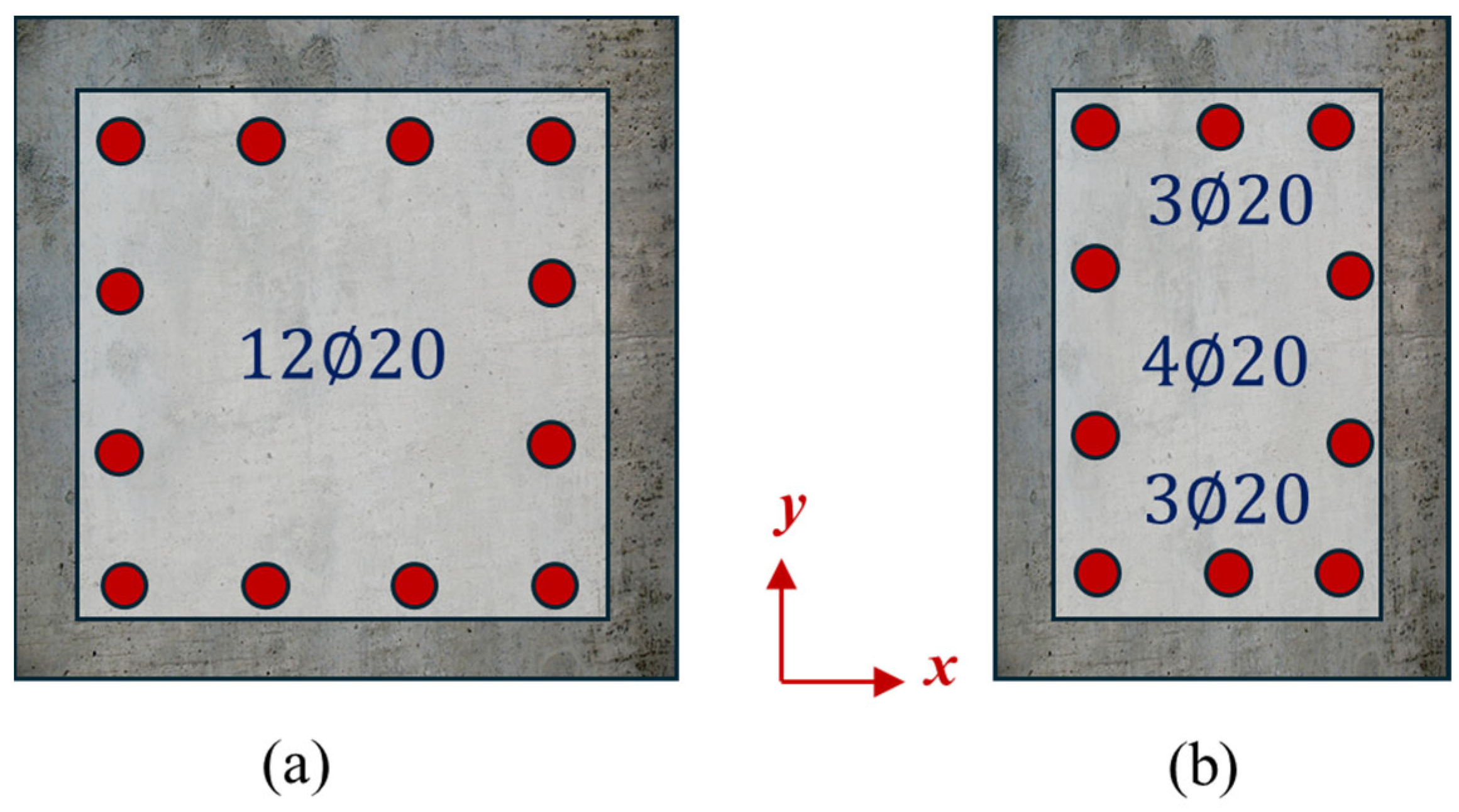
The design of the columns features symmetrical arrangements of longitudinal steel positioned around the edges of the cross section. This approach facilitates a homogeneous confinement zone, mitigates flexural distortion resulting from eccentric axial loads, and maintains uniform stiffness in relation to each principal axis. Specifically, twelve longitudinal bars, each measuring 20 mm in diameter, are distributed in evenly spaced clusters along the perimeter. Conversely, the beams within these precast frames incorporate three longitudinal reinforcements of 20 mm diameter at both the top and bottom, along with four additional 20 mm bars situated in the middle segment. A schematic illustration of the reinforcements is given in
Figure 7.
The design methodology has yielded the specified ACPH configuration. The cross-sectional dimensions of the ACPH element are 25 cm by 40 cm, aligning with the measurements of the beam. Additionally, the length of the ACPH element and its placement concerning the column surface were determined based on the height of the beam, following the guidelines established in the cited article.
This analysis aims to evaluate the efficacy of the ACPH method in enhancing the seismic performance of PRC frames subjected to significant ground motions. This is achieved by modeling and analyzing four distinct frame configurations: 1B1S, 1B2S, 2B1S, and 2B2S, both with and without the installation of the replaceable hinge connectors at the beam–column junction.
Figure 8 depicts four distinct finite element models (FEMs) that exclude the ACPH, each showcasing a unique arrangement of precast frames with varying structural configurations. The same figure also includes an FEM representation of the same frames integrated with the ACPH. Conversely, a meshed depiction of the ACPH is presented in
Figure 9. By comparing the dynamic responses and deterioration between frames that utilize ACPHs and those with conventional precast joints, the research elucidates the capability of this specialized hinge subassembly to localize damage more effectively while improving the overall ductility of the structures during intense seismic activity.
This comparative methodology allows for the precise identification of whether the ACPH successfully redistributes plastic deformations away from critical elements such as beams or columns into a replaceable segment, thereby reducing the long-term damage potential to the primary concrete components. By maintaining identical geometrical configurations across all frames, any behavioral difference observed can be attributed solely to the provision or absence of the ACPH device, eliminating the influence of size or reinforcement variability.
All frames were subjected to uniform strong ground motions, facilitating the assessment of how the incorporation of a steel-based hinge assembly alters failure modes, stiffness loss, and energy dissipation properties. Observable differences in these metrics substantiate the practical advantages of including a replaceable plastic hinge in precast frames that are otherwise prone to brittle joint failures. Thus, the analyses not only clarify how ACPHs contribute to enhanced seismic resilience but also explore potential limitations or situations where their effectiveness may be diminished. This includes an evaluation of frame performance at varying drift levels, the concentration of inelastic rotations, and the need for maintenance of connector designs to avoid issues such as bolt loosening or steel fatigue. Ultimately, the objective is to ascertain whether the ACPH consistently delivers superior performance relative to traditional wet joints or minimally detailed connections, positioning it as a feasible alternative for various precast applications in areas prone to moderate-to-high seismic activity.
4.5. Loading Regime
The evaluation of seismic performance outlined here operates on two primary levels. Initially, a dynamic implicit simulation is executed using a representative segment of the Mw 7.7 Kahramanmaraş earthquake record. Using the implicit dynamic solver included in ABAQUS [
33], which is based on the Newmark-beta integration approach as described by Bathe [
42], nonlinear time-history analyses were conducted in this work. By solving the linked system of equilibrium equations, this formulation naturally includes the consequences of inertia:
where
represents the consistent mass matrix,
is the damping matrix, and
is the developing tangent stiffness matrix. The time-varying effective force applied at the base is denoted by the word
. Inertial forces, resulting from mass acceleration, are calculated at every time increment and immediately affect the worldwide response when the structural system reacts to seismic stimulation.
Dynamic amplification events are recorded by the simulation framework as a natural result of modal development and stiffness deterioration. The stiffness matrix shows incremental softening as inelastic deformations accumulate, especially inside the ACPH subassemblies, causing changes in the fundamental frequency of the structure and increasing the demands in certain modes. These consequences result from the interplay of material nonlinearity and inertial reaction, not artificial imposition.
Rayleigh damping was included to simulate actual energy dissipation during shaking; it was set to reach around 5% critical damping in the first two vibration modes of the undamaged frames. This degree of damping corresponds to standard levels used in performance-based earthquake engineering for RC structures.
Although the implicit approach has its drawbacks, it provides strong convergence and consistent temporal integration even in very nonlinear settings. When damage starts or advances quickly, the approach calls for rather tiny time increments to preserve accuracy, which might raise computing time. The internal stabilization methods employed to improve numerical convergence may also marginally reduce high-frequency material, so the approach is more appropriate for obtaining global response metrics (e.g., drift, base shear, and damage localization) than for resolving extremely short-duration transients.
The analysis specifically isolates a critical 10 s interval surrounding the record’s peak acceleration, concentrating on the phase of peak acceleration to capture essential inelastic responses. The ground motion considered is illustrated in
Figure 10, which also highlights the isolated interval on the graph.
In the dynamic implicit analysis, the most intense base accelerations corresponding to the earthquake are applied to the supports of each frame. The computational solver iteratively processes each small time step, continuously adjusting system stiffness and damping in reflection of the changes in material states. During increased shaking, localized concrete cracking occurs, reinforcing bars may undergo yielding, and plastic deformations are noted particularly around beam–column joints or at specialized ACPH devices.
The analytical outputs, including time histories of base shear, inter-story drift, and localized damage, reveal the responses of each frame, whether equipped with an ACPH or not, under real-time seismic forces characterized by inertia and dynamic amplification effects. Only a single nonlinear dynamic analysis was conducted for each frame configuration, using the 10 s interval extracted from the 2023 Kahramanmaraş earthquake record. No additional static or quasi-static loading procedures were applied.
The comparative analysis of outcomes, from the dynamic implicit analyses under the Mw 7.7 record, yields an extensive overview of both in-service performance and the ultimate capacity for each frame configuration. The earthquake simulation effectively emulates real-world loading histories with inherent inertia and velocity effects.
5. Results
This section presents the numerical results derived from the dynamic implicit analyses of the Mw 7.7 Kahramanmaraş ground motion conducted on each of the four precast frame configurations. A comparative analysis between frames equipped with an ACPH and those utilizing traditional wet-joint connections is undertaken. This analysis elucidates the impact of modifications at the beam–column interface on key parameters such as fundamental periods, base shear demands, and plastic hinge development. The chosen performance metrics, which encompass moment capacities, peak drifts, hysteretic responses, and residual deformations, provide insight into the effectiveness of the ACPH in localizing inelastic deformations and subsequently enhancing the overall ductility of these precast structures.
5.1. Modal Analyses
An analytical examination of a comparative modal analysis indicates that frames equipped with ACPH devices possess a somewhat extended fundamental period compared to those utilizing conventional wet connections. This extension results from the hinging mechanism, which diminishes the effective lateral stiffness at the beam–column interface, thereby causing a downward shift in the system’s predominant vibration mode toward lower frequencies. The increase in period typically ranges from 10 to 30 percent, contingent upon the specific geometry of the frame. Such an elongation may mitigate seismic demand on the structure, given that spectral accelerations tend to decrease at longer periods, particularly in areas susceptible to moderate-to-high seismic hazards. Conversely, frames that utilize monolithic (wet) connections exhibit heightened initial stiffness but are likely to experience elevated base shear forces during dynamic excitations. The overall consequence is that ACPH frames are likely to experience a slight reduction in seismic force demand due to their extended periods and may also facilitate a more controlled inelastic behavior at the replaceable hinge, which could enhance their overall ductility and resilience to severe ground motion.
Table 3 summarizes the results of the modal analysis.
5.2. Dynamic Analyses
An analytical examination of the base shear–time graphs derived from the chosen earthquake record yields the following observations. In the case of frames characterized by two spans, an analysis was conducted to evaluate the base shear values transmitted by the central column in relation to other parameters.
The analysis of the base shear–time graph presented in
Figure 11a for the 1B1S frame reveals that the maximum base shear force for the RC frame is 1400 kN, whereas the ACPH frame reaches a lower peak of 934 kN. This demonstrates a substantial decrease of 51% in base shear for the ACPH frame when compared to its RC equivalent. Temporal analysis indicates that the RC frame achieves its maximum base shear at 5.09 s, while the ACPH frame does so slightly earlier at 5.03 s during the recorded earthquake event. In
Figure 11b, the base shear–time graphs for the 1B2S frames show that the RC frame attains a peak base shear force of 876 kN, contrasting with the ACPH frame, which has a significantly lower peak of 468 kN. This results in a considerable reduction of 93% in base shear for the ACPH frame against the RC frame. The timing analysis further indicates that the RC frame reaches its peak at 5.08 s, whereas the ACPH frame does so much earlier at only 2.03 s. Moving on to
Figure 11c, the base shear–time graph for the 2B1S frames indicates that the RC frame records a maximum base shear force of 2339 kN, compared to the ACPH frame’s noted base shear force of 1446 kN. This results in a reduction of 65% for the ACPH frame in relation to the RC frame. Analysis of the peak timing indicates that the RC frame achieves its maximum at 5.04 s, while the ACPH frame records this value slightly later at 5.09 s. Lastly,
Figure 11d illustrates the base shear–time graphs for the 2B2S frames, where the RC frame has a maximum base shear force of 1596 kN, whereas the ACPH frame demonstrates a notably lower peak of 768 kN. This analysis reveals a significant reduction of 108% in base shear for the 2B2S configuration. Furthermore, the timing of peak base shear reveals that the RC frame reaches its maximum at 5.08 s, while the ACPH frame achieves this at 4.92 s, indicating a slight variation in response times.
An analysis of the base shear variations in the 1B2S and 2B1S frame configurations, both exhibiting an identical number of ACPHs, reveals that the 1B2S frame, characterized by an increased number of stories, experiences a more significant reduction in base shear. Furthermore, upon examining the structural period data, it becomes evident that the increment in stories plays a more substantial role in elongating the structural period. Consequently, one can infer that a greater vertical expansion of the structure yields more pronounced effects on both the increase in period and the alterations in base shear.
An analysis of the distribution of base shear across middle columns in two-bay frames reveals noteworthy differences in the proportion of shear attributed to these columns. At 5.09 s, during the peak base shear of the 2B1S ACPH frame, the middle column accounts for 35.64% of the total base shear. Comparatively, in the RC frame at this same moment, the middle column is responsible for a larger share, specifically 41.13%. At 4.92 s, when the 2B2S ACPH frame reaches its maximum base shear, the middle column’s contribution is slightly lower, at 35.16%. In contrast, the RC frame at this time shows the middle column carrying 38.38% of the base shear. These data indicate that the implementation of ACPH technology leads to a proportional decrease in the base shear allocated to the middle column, thus facilitating a more equitable distribution of shear among the frame’s columns.
The findings illustrated in
Figure 12,
Figure 13 and
Figure 14 collectively underscore the pronounced disparities in damage distributions between frames characterized by traditional RC joints and those integrated with the advanced energy dissipating ACPH system. In the reference RC frames, both compression and tension damage indices approach or exceed the threshold of 0.85 in proximity to the beam–column connections, particularly at the extremities of the beams where the formation of plastic hinges is typically observed. These regions are also associated with the highest levels of plastic strain, indicating extensive cracking, the potential for concrete crushing, and the yielding of the reinforcement in the absence of a specialized energy dissipation mechanism.
Conversely, the frames equipped with the ACPH system demonstrate a significantly divergent damage pattern. The indices for both compression and tension remain considerably lower, typically below 0.3 across most concrete areas, including the critical joint zones. The plastic strain distributions reveal that inelastic deformation is sharply concentrated within the steel plates of the ACPH, particularly in the 3 mm Q235 fuse zones. In these areas, strain levels indicative of yielding is attained, while the surrounding concrete and longitudinal reinforcement largely remain within the elastic domain.
These disparities substantiate that the ACPH mechanism effectively diverted inelastic demand away from the RC frame and directed it towards the designated sacrificial component. The hinge adeptly performed its role by localizing energy dissipation, thereby reducing structural damage and maintaining the integrity of the primary load-bearing framework. This confinement of damage represents a crucial performance criterion for resilient seismic design, as it facilitates post-event reparability and mitigates the risk of progressive damage throughout the frame.
5.3. Damage Patterns
The damage visualizations in this section correlate to the time step at which the frame exhibits its highest seismic reaction, often linked to peak base shear or inter-story drift. The findings do not represent the conclusive stage of the investigation but rather the peak of structural demand, which most clearly demonstrates damage localization. An analysis of damage patterns in concrete has been conducted using the tension and compression damage variables established in the CDP model. This analysis reveals significant differences between frames employing traditional RC beam–column joints and those equipped with ACPH devices. In conventional frames lacking an artificial hinge, beam ends situated near the column faces tend to experience considerable tensile cracking, as evidenced by elevated tension damage values. Furthermore, compressive failure may arise at the upper or lower fibers of the beam if subjected to substantial inelastic rotations. Such cracking can sometimes extend into the edges of the column, resulting in a widespread damage zone that undermines the structural integrity of the joint. Conversely, the introduction of the ACPH subassembly results in the tension and compression damage distributions within the RC being largely contained to minor cracking areas that occur at mid-span or around the column base. This pattern of damage is notably less severe than that observed in traditional RC joints. The predominant inelastic demands are instead transferred to the steel hinge plates, which display distinct yielding as indicated by plastic strain contour plots, particularly in regions where the replaceable fuse element is intentionally designed to be weaker in bending. This concentration of steel deformation mitigates the risk of extensive cracking or crushing in the surrounding concrete, thereby safeguarding the stability of both the beam and column.
Visual assessments of FEM compressive damage outputs have been illustrated in
Figure 12.
Upon examining the compression damage present within the frames,
- (a)
It was determined that all frames exhibited signs of compression damage at the base of the columns;
- (b)
In the analysis of the beams within the one bay characterized as 1B1S and 1B2S frames, it is noted that the peak compressive damage limit recorded in the RC frame adjacent to the column face reached a value of 0.87. However, in the ACPH frame, compressive damage near the column face in the beam is minimal, approaching zero. Furthermore, it was observed that the middle beam, situated between the ACPH frames, exhibited no signs of compressive damage. This pattern remains consistent across both single-story and double-story frames, indicating that an increase in the number of stories does not significantly affect the level of compressive damage observed;
- (c)
An analytical examination of the beams within the 2B1S and 2B2S frame configurations reveals that the highest extent of compressive damage, as delineated in the reinforced concrete (RC) frame, near the exterior columns and adjacent to the middle column’s face, reached a value of 0.87. Furthermore, compressive damage was additionally identified in the beam–column joint area associated with the middle column. When analyzing the ACPH frame, the extent of compressive damage near the column face and within the joint area of the middle column is observed to be approximately 0, with no compressive damage recorded in the middle beam situated between the ACPHs. These findings are consistent across both two-story and one-story frames; the increment in story count did not significantly affect the compressive damage levels, given that the damage recorded at the first story was sufficiently low.
The tensile damage outputs produced by the finite element method (FEM) have been represented visually in
Figure 13. An analysis of the tensile damage observed within the frames reveals important insights.
- (a)
An examination of the tensile damage within the structural frames reveals that the columns of the first story in all frames attained the established tensile damage threshold of 0.90. Within the framework of the CDP model, the tensile damage variable spans from 0.0 (undamaged) to 1.0 (total cracking with no tensile stiffness left). A score of 0.90 indicates that the tensile capacity in the afflicted area is virtually depleted, often interpreted as severe but not yet catastrophic cracking. This barrier was not externally imposed but arose from material deterioration due to cyclic stress. This research used values near 0.90 as qualitative indicators of significant damage intensity, especially at beam–column junctions. The CDP approach does not provide a definitive “failure” threshold; nonetheless, locations with damage indices over 0.85 were deemed likely to need post-earthquake repairs, aligning with standard methods in damage-oriented seismic evaluation. Moreover, in the columns situated on the second story, the application of ACPH resulted in a modest decrease in tensile damage in the region of the beam–column joint;
- (b)
In the examination of the beams within the 1B1S and 1B2S frame configurations, it is noted that the RC frame experiences tensile damage that has approached the critical limit of 0.9. This high damage zone begins at the column face and extends toward the midspan of the beam. Meanwhile, the tensile damage observed near the midpoint ranges between 0.45 and 0.7. Conversely, within the ACPH frame, tensile damage similarly reaches the threshold of 0.90 near the column face. However, the integration of replaceable joints significantly mitigates tensile damage in the central beam situated between the ACPH frames. This reduction in tensile damage attributed to the ACPH system is particularly pronounced on the second floor, especially as the number of stories increases;
- (c)
In analyzing the beams of the two-bay frames, specifically the 2B1S and 2B2S configurations, it is observed that the RC frame has attained a tensile damage threshold of 0.9, measured from the column face to the vicinity of the beam’s midpoint. In contrast, tensile damage recorded near the midpoint is approximately between 0.45 and 0.7. In the case of the ACPH frame, tensile damage similarly reaches the limit of 0.90 in the section of the beam adjacent to the column face. However, as evidenced in the one-bay frames, the integration of ACPH results in a significant reduction in tensile damage within the middle beam situated between the ACPHs when compared to the RC frame. Notably, this reduction in tensile damage becomes increasingly evident on the second floor as the number of stories rises;
- (d)
The implementation of ACPH is likely to aid in the preservation of middle beams in an undamaged state, aligning with the underlying principles associated with the utilization of replaceable connections.
The outcomes of the plastic strain damage simulated using the FEM are represented visually in
Figure 14. In this figure,
- (a)
The plastic strain value in the earthquake direction, denoted as PE33, indicates that the area experiencing the highest strain in both RC frames and ACPH frames is located at the base of the columns;
- (b)
In the analysis of one-bay frames designated as 1B1S and 1B2S, the data indicate that the PE33 value reaches its peak intensity near the column face of the beam at the first floor of the RC frame. Within the central portion of the beam, however, the plastic strain value registers at its lowest level. The integration of replaceable joints within the ACPH frame has resulted in a significant reduction in the PE33 value, observed in both the region adjacent to the column face and the mid-span of the beam between the ACPH elements. Notably, the distribution of plastic strains tends to concentrate on the energy absorption plates, which have a thickness of 3 mm. This observation supports the premise that the design objective of facilitating plasticization within the energy dissipation plates—as intended through the use of replaceable joints—has been effectively realized. In the case of the two-story frame, similar patterns of plasticization are evident at the upper level, specifically on the energy dissipation plates associated with the ACPH configuration;
- (c)
In analyzing the two bay frames, designated as 2B1S and 2B2S, it was noted that the first-floor beams of the RC framework exhibited signs of plasticization adjacent to both the outer column face and the mid-column faces. Furthermore, upon integrating a replaceable joint into the ACPH frame, consistent with the configuration observed in single-bay frames, the region of plasticization corresponded to the 3 mm-thick energy dissipation plates inherent to the ACPH design. When the span increased, the middle column did not exhibit any plasticization; however, plasticization was observed in the ACPH components located to the left and right of the middle column.
The visualization of von Mises stress values is illustrated in
Figure 15. This metric involves quantifying both normal and shear stresses to characterize the point of material failure, specifically in terms of yielding. The evaluation of von Mises stresses across the frames revealed that the replaceable joints in all configurations exhibited stress distribution consistent with their intended design. The primary expectation for these joints is that the 3 mm-thick energy dissipation plates located in both the upper and lower sections will first reach their yield strength and undergo plastic deformation, while the remainder of the joint structure remains in the elastic range. Consequently, it is evident that all frames demonstrate that the replaceable joints function as designed. Notably, in the joint region of the central column, identified as the area experiencing the highest stress, there was a significant contribution to maintaining the column’s performance within elastic limits, aligning with the intended function of the joint.
The simulation findings provide significant evidence for the damage localization capability of the ACPH system.
Figure 12 and
Figure 13 show that the tension and compression damage indices in typical RC frames hit critical levels (0.87 to 0.90) close to beam–column interfaces, suggesting major cracking and even concrete crushing. By comparison, the ACPH-equipped frames showed much lower damage values as the indices stayed below 0.2 throughout the connecting zones. This difference draws attention to a significant movement in inelastic energy absorption from concrete and into the specific steel subassembly.
The plastic strain fields (
Figure 14) support this trend even further. Plastic deformation was common in RC frames and ran into both beam ends and column edges. In frames with ACPH, plastic stresses, however, were severely localized within the energy-dissipating steel plates. While the surrounding concrete remained mostly elastic, the PE33 values in some areas hit critical yielding levels. Corresponding to the 3 mm Q235 steel fuse plates, this plastic concentration was particularly chosen for its flexibility and low yield strength in relation to other structural components.
The von Mises stress distribution in
Figure 15 further verifies that the ACPH effectively attained and maintained yielding in its assigned fuse areas without notable overstress in either the beams or columns. This obvious damage localization confirms the functional significance of the hinge as a sacrificial energy dissipation mechanism. The numerical data thus back up the finding that the ACPH preserves the integrity of the main RC frame while providing a repeatable, targeted way to regulate inelastic deformation.
This targeted plastic deformation within the ACPH steel plates not only preserves the surrounding concrete but also enhances the overall seismic energy dissipation capacity of the system. Across all frame types, the ACPH-equipped configurations exhibited reductions in peak base shear values, with differences reaching as high as 51% compared to their RC counterparts. Moreover, the calibrated equivalent viscous damping ratio of approximately 10% confirms that the hinge mechanism is effective in dissipating energy beyond the levels typically observed in monolithic reinforced concrete systems. These findings demonstrate that the ACPH system not only localizes damage but also strategically redistributes strength demand to sacrificial steel elements, improving both structural resilience and post-earthquake reparability.
6. Discussion on the Results
The findings outlined in the previous section underscore the significant impact of the ACPH system on crucial seismic performance metrics across different structural arrangements. In order to place these results within the larger framework of engineering goals, the ensuing analysis examines their consequences for structural efficiency, scalability, practical applicability, and inherent limitations. Additionally, this segment delves into the role of the ACPH system in fulfilling performance-based design objectives, notably in improving reparability, managing damage, and facilitating resilient recovery in the aftermath of substantial seismic occurrences.
6.1. Structural Efficiency of the ACPH System
From an analytical perspective, the notable yet steady reduction in base shear observed in ACPH frames has substantial implications for the overall structural framework. This decrease in maximum lateral forces facilitates a relaxation of the foundation specifications and lessens the bending and shear demands on the columns, thereby indicating potential financial efficiencies in materials and construction practices. Moreover, the implementation of the artificial hinge mechanism is precisely engineered to constrain plastic inelasticity to a designated steel component, which effectively restricts concrete damage to minor surface cracking. Consequently, repair processes following a seismic event can be streamlined, focusing on the replacement or reinforcement of hinge plates rather than engaging in extensive restoration of larger sections of damaged concrete or dealing with re-lapping procedures for compromised rebar at the ends of beams. Additionally, the hinge unit’s capacity for bolting or pinning to the main beam framework introduces an option for disassembly and transportation, which proves advantageous for prefabricated industrial or temporary structures. In summary, this design ethos not only meets performance criteria during significant seismic incidents but also simplifies post-earthquake maintenance, thereby promoting the potential for the entire structure’s future reusability.
6.2. Comparative Assessment of Alternative Precast Beam–Column Connection Strategies
Alternative precast beam–column connection methodologies, such as grouted sleeves or post-tensioned unbonded bars, are frequently designed to achieve monolithic behavior, facilitating moment transfer through mechanical couplers or cables to simulate the continuity typical of cast-in-place constructions. Although these systems can exhibit adequate ductility under moderate loading conditions, they introduce complexities in design, installation, and maintenance. Strict management of grout tolerances or the anchorage zones of cables is essential to mitigate issues related to slippage or loss of prestressing over time. In contrast, the ACPH approach incorporates a more straightforward, intentionally weaker hinge mechanism at the beam’s end, focusing on localizing inelastic rotations within a replaceable steel component instead of relying on continuous rebar or high-tension cables throughout the joint. From a production perspective, fabricating a limited number of standardized hinge plate subassemblies is likely to be less labor-intensive compared to the meticulous control required for multiple coupler placements or the precise tensioning of extended unbonded cables. Furthermore, the ACPH design greatly streamlines post-earthquake repairs, instead of addressing cracking around sleeves or the challenges of detensioning cable systems, one can simply detach the damaged hinge plates and replace them with new ones, thus preserving the integrity of the main beam and column. This simplicity in manufacturing and reparability, combined with the flexibility to swiftly disassemble or relocate structural modules, may lead to significant cost reductions in both construction and lifecycle management.
6.3. Comparative Performance Across Frame Configurations and Scalability of ACPH
A comparison study of the four frame setups shows regular patterns in how the ACPH system affects seismic performance across different geometries. The inclusion of ACPH devices in all configurations resulted in considerable reductions in peak base shear, higher global ductility, and clear damage suppression in concrete members, suggesting a robust and repeatable protective impact. Higher flexibility in the upper stories caused the ACPH’s effect on fundamental period elongation to be more noticeable in the transition from 1-story to 2-story frames. Particularly in the longer-period range, this change in dynamic properties lowered seismic demand and helped achieve more relative decreases in base shear. For example, the base shear in the 1B2S design was lowered by more than 46% when compared to its monolithic RC equivalent.
The change from single-bay to two-bay setups (1B1S to 2B1S) also showed that the ACPH remained effective in multi-hinge systems with well-distributed strain localization and no negative contact between neighboring hinges. ACPH-equipped 2B frames had less central column base shear share, suggesting improved load dispersion and lower demand concentration. Importantly, in all configurations, plastic stresses were localized inside the steel fuse plates of the ACPH subassemblies, and both tensile and compressive damage in concrete stayed below critical thresholds. These trends persisted even in the most complicated scenario (2B2S), hence verifying the scalability and robustness of the ACPH technology with performance apart from frame size or arrangement.
These results substantiate the notion that the ACPH system is efficient not just in isolated subassemblies but also in whole structural systems of escalating complexity. To quantify this enhancement, basic demand-to-capacity ratios (DCRs) were computed using engineering limit states. A serviceability drift limit of 1.0% and a near-collapse threshold of 3.0% were presumed based on existing design standards (e.g., FEMA 356 [
43]; Eurocode 8 [
44]). The maximum drift in ACPH-equipped frames was between 0.6% and 0.9%, whereas conventional RC frames exhibited values from 1.3% to 1.7%, contingent upon the frame type. These findings indicate DCR reductions of 40–55% favoring the ACPH frames.
Furthermore, RC frames devoid of ACPH had damage indices nearing 0.90 and significant plastic stresses in both concrete and reinforcement. Conversely, the ACPH constructions exhibited damage indices consistently around 0.3, with plastic deformation localized in the steel fuse plates. The findings demonstrate that ACPH-equipped frames maintain adequate structural performance under both serviceability and near-collapse circumstances. The integration of ACPH enhances global resilience and localized damage mitigation in a measurable way.
6.4. Limitations and Future Validation Needs
The findings presented here suggest notable advantages for the application of ACPH systems in low-to-mid-rise buildings. However, it is essential to recognize that taller structures are likely to experience significant second order (P-Delta) effects, which can lead to increased story drifts and heightened demands on structural columns. This may ultimately negate some of the benefits associated with localized ACPH hinge behavior. Therefore, the implementation of ACPH designs in high-rise or multi-span continuous frameworks necessitates advanced analytical approaches that account for complex geometric nonlinearities and rigorously detailed incremental dynamic simulations.
Moreover, while the numerical analyses illustrate how ACPH connections facilitate repair processes, it is paramount that validation occurs through large-scale physical testing. Such testing ideally utilizes multi-degree-of-freedom shake tables to effectively capture higher-mode responses and realistic shear demands on joints. In conjunction with these experimental efforts, conducting a comprehensive life-cycle cost analysis would provide valuable insights into the financial advantages of promptly replacing hinge plates following seismic events, as opposed to facing substantial downtime associated with repairing traditional monolithic RC damage.
Additionally, the inherent exposure of steel components within an ACPH system underscores the critical need for effective corrosion protection and meticulous detailing. The successful preservation of hinge plates and bolts in a rust-free and fatigue-resistant condition throughout the service life of the structure is contingent upon the implementation of protective coatings, gaskets, or easily applicable corrosion inhibitors. Although these design considerations introduce a degree of added complexity, they are crucial for ensuring that the hinge continues to function predictably and remains safe for either reuse or replacement when necessary.
6.5. Practical Implementation Considerations
In addition to its structural efficacy, the ACPH system, initially designed as a modular hinge for precast joints, provides many pragmatic benefits for actual construction and post-seismic rehabilitation. The fundamental elements of the system, including the energy-dissipating steel plates and bolted end-plate assemblies, are constructed from normal carbon steel (Q235 and Q345) and can be manufactured with regular machining techniques without the need for specialist materials or specific equipment. This simplicity improves the system’s scalability and facilitates its incorporation into both precast production operations and in situ retrofit processes.
The installation of the ACPH in precast frames may be integrated into current workflows by affixing the hinge assembly at the beam ends before lifting, using bolted or welded connections to link with the column face. In contrast to wet joints or grouted sleeves, the ACPH needs neither curing time nor precise grout injection, hence minimizing construction delays and reliance on on-site manpower. Subsequent to a seismic incident, the interchangeable steel plates may be accessible and replaced without invasive demolition. The device’s accessible design enables post-earthquake examination, enabling maintenance staff to see assess deformation or yielding in the steel plates.
From a long-term durability perspective, it is essential to consider protection against corrosion and fatigue, especially in external or industrial settings, as also emphasized in the PCI Design Handbook [
1]. This may be mitigated by galvanization or protective coatings, as well as by integrating gaskets or sealants at the beam–column junction to avert moisture infiltration. The ACPH’s mechanical simplicity, modular design, and replaceability provide considerable benefits for life-cycle cost and resilience-oriented asset management. The concept of replaceable yielding elements as a strategy for resilience and maintainability aligns with recommendations in FEMA P-58 [
37], where component-level substitution is prioritized to minimize recovery time.
6.6. Future Research Directions and Code Integration Potential
The current investigation validates the seismic efficacy of the ACPH system under dynamic conditions through sophisticated nonlinear simulations, yet additional research is imperative for broader recognition and integration into design methodologies. The numerical outcomes highlighted in this study necessitate corroboration via extensive experimental assessments on complete precast frame systems that incorporate ACPH subassemblies. Specifically, shake table experiments are essential to discern higher-mode influences, torsional requirements, and cumulative inelastic deformation, thereby evaluating the practical performance of the hinge during multi-directional seismic events.
Beyond dynamic evaluations, focused research on low-cycle fatigue, strain-rate responsiveness, and corrosion resistance is crucial for determining the ACPH system’s long-term durability and operational characteristics. Such investigations would contribute to establishing benchmarks for component replacement, anchorage detailing, and protective measures, especially in exterior or industrial contexts.
For the ACPH system to be incorporated into established building regulations and performance-based design criteria, it must satisfy the validation standards specified in frameworks like FEMA P-695 [
45]. These documents outline essential performance parameters concerning hysteretic stability, predictability of failure mechanisms, and measurable deformation capacities, all of which require validation through a synthesis of experimental and numerical data. Given its capacity for replaceability and localization of inelastic behavior, the ACPH system holds potential alignment with resilience-based design approaches, such as those articulated in FEMA P-58 [
5], which prioritize post-disaster recoverability and repairability of components within seismic performance outcomes. To achieve a regulatory framework for adoption, a thorough design protocol must be established, incorporating standardized geometries, specifications for steel grades, hinge-to-beam capacity ratios, and detailing constraints. The findings of the present study supply a rigorously calibrated numerical basis to support such standardization initiatives, concurrently identifying critical behavioral indicators that should be emphasized in forthcoming testing and code development efforts.
This study assesses four unique frame configurations to represent geometric variation in vertical and horizontal dimensions, recognizing that additional parametric analyses would enhance the generalizability of the results and aid in formulating prescriptive design guidance for the ACPH system. Subsequent studies will concentrate on methodically altering beam and column dimensions, material strength classifications for both reinforced concrete components and steel plates, beam spans, column heights, and hinge placement offsets to assess the impact of each variable on structural performance.
These studies will facilitate the creation of a design matrix for optimizing ACPH installation, including the selection of plate thickness, steel grade, and connection position predicated on demand-to-capacity ratios and seismic intensity levels. The results of this research provide a core framework, validating the efficacy of ACPH across various frame geometries and illustrating its potential as a scalable and robust retrofitting technique.
7. Conclusions
This investigation assessed the seismic resilience of inadequately designed precast reinforced concrete frames integrated with a modular, interchangeable plastic hinge system, utilizing comprehensive nonlinear finite element modeling validated by empirical data. The computational analyses illustrated that the ACPH mechanism was proficient in confining plastic deformation within the steel hinge plates, while safeguarding the structural integrity of the adjacent concrete components and embedded reinforcements. This phenomenon was consistently noted across all four frame configurations, encompassing single- and two-story, single- and dual-bay frames, subjected to realistic seismic excitations.
The numerical results demonstrated that the ACPH-equipped frames achieved substantial reductions in peak base shear, ranging from 33% in the 2B1S configuration to over 51% in the 1B2S case, compared to monolithic RC counterparts. Additionally, the structural periods of the ACPH frames increased by 10–30%, contributing to decreased spectral demand. Damage indices revealed that tensile and compressive damage in the concrete remained below 0.3 in ACPH systems, whereas RC frames reached or exceeded 0.85 near beam–column joints. The equivalent viscous damping ratio for the ACPH system, validated against experimental data, stabilized at approximately 10%, nearly double that of conventional reinforced concrete configurations.
These results bolster the overarching aims of resilience-oriented seismic design, which prioritize not only structural robustness and life safety but also the capacity to mitigate damage, decrease repair durations, and facilitate swift functional recovery in the aftermath of significant seismic events. By permitting component-level energy dissipation and circumventing permanent damage to primary structural elements, the ACPH system presents a viable approach to enhancing the post-event performance and operational functionality of precast concrete structures.
While the results are primarily relevant to non-compliant structures exhibiting material deficiencies, the foundational design philosophy can be adapted to contemporary precast systems. Future investigations, encompassing full-scale evaluations and integration with code-compliant detailing methodologies, will be crucial for fostering broader implementation and standardization.


