1. Introduction
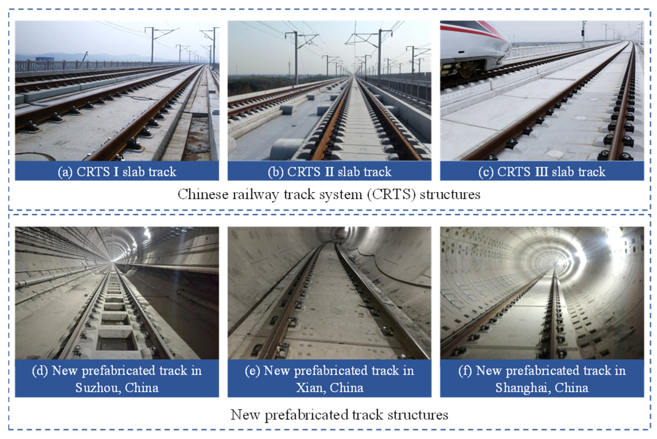
As a fast and efficient mode of transportation, railways have developed rapidly in recent years. In China, as the high-speed railway network is gradually densified, the construction of urban express lines and urban rail transit systems between neighboring cities has also sped up. Various railway lines with different speed classifications cause more diversified demand for track structures. So far, a series of track structures of the Chinese railway track system (CRTS) are widely used in high-speed railways, intercity railways and many other railway lines in China. With the advancement of construction technology, the prefabricated track slabs, which are standardized and convenient for construction, have also gradually developed [
1]. Under such a background, many new track structures have been generated and mainly used in some new urban express railway lines, which are relatively more lenient in criteria compared with the high-speed railway because of lower train speeds. The different track structures in China are shown in
Figure 1, including CRTS tracks and some new prefabricated tracks. However, in different railway line classifications, the safety design values of size and reinforcement for track structures vary accordingly. Therefore, to accommodate the diversified development of railways in the future, the safety, flexibility and efficiency of the railway track design method is very essential.
For track design under different conditions, appropriate design loads are vital for the adaptability of the structures. The size and reinforcement design according to expected loads should not only meet the requirements of safety, comfort and durability but also be more efficient. So, higher requirements are put forward for the design methods [
2], and design loads should also be validly considered. So far, many scholars have studied the mechanical characteristics of a ballastless track under different loads [
3], which provides important support for track design. Among the long-term loads on the track structure, the foremost one is the train load. Many scholars have conducted research on the dynamic and static mechanical properties of the track system under train loads [
4,
5,
6,
7,
8]. Chen [
5] et al. constructed a full-scale model of a ballastless track on a subgrade and studied the dynamic response of the track and subgrade under different train speeds via experiments to obtain a rational dynamic load magnification factor. Ren [
6] and Zhang [
7] analyzed the mechanical properties of railway tracks under train loads and revealed the influence law of wheel weights, speeds, load lengths and other parameters. Zhang [
8] et al. proposed a new type of prefabricated slab track and verified its service performance under large freight train loads and fatigue train loads using numerical and experimental methods. In addition, the performance of the track structures is also affected by temperature changes [
9,
10,
11,
12]. Dong [
12] et al. compared and analyzed the mechanical characteristics of unit slab tracks and piecewise slab tracks under a temperature gradient load, and the results showed that the coupling effect of the temperature gradient and train load would affect the vertical stability of track, and the stress and deformation of unit slab track were more significant. Furthermore, the influence of the deformation of the foundation on the track structure cannot be ignored either [
13,
14,
15,
16]. Sun [
15] et al. analyzed the influence of uneven subgrade settlement (USS) on structural stress, deformation and damage of CRTS III slab tracks. The main parts and positions damaged and the most unfavorable wavelength range of USS are indicated. Zheng [
16] et al. developed a segmental experimental model and studied the deformation characteristics of ballastless tracks under deformation of a long-span bridge by adding a test load. The research above on the mechanical characteristics of a ballastless track not only provided reference for the load values but also verified the design methods.
In terms of track design theories and methods, they have gone through a lengthy developmental trajectory, and two mainstream methods emerged: the allowable stress method (ASM) and the limit state method (LSM). Since the mid-19
th century, to ensure the safety and reliability of railway infrastructure, the ASM has been used in structural analysis and design at the stage of material elasticity [
17]. This method is based on linear elasticity theory, and the calculation is very simple and convenient [
18,
19]. In China, based on the allowable stress method, the Code for the Design of Railway Tracks (TB10082-2017) [
20] specifies the design loads and load effect of tracks and guides the structure design of ballastless tracks in earlier times. However, due to the adoption of a single empirical safety factor [
21], the ASM cannot maintain a consistent safety level for various structures [
22,
23]. At the same time, it also has a large design margin for design of track structure, which leads to the waste of materials [
24]. So, there is still room for optimization and perfection.
With the improvement in structural reliability theory, the LSM based on probability theory has begun to develop gradually [
25,
26]. International standards such as the Analysis and Design of Reinforced and Prestressed Concrete Guideway Structure (ACI 358.1R-92) [
27] began to use reliability methods as the basis for safety analysis [
28]. The LSM was also used in the design of railway track gradually. Kaewunruen Sakdirat et al. [
29,
30] found that the LSM can give full play to the fracture toughness of structures, which can reduce the material cost of each railway by 15%. However, compared with European and American countries, Chinese railway system reliability research started later. To adapt to more refined design, by learning from successful cases of foreign specifications, relevant design specifications of China were officially promulgated in 2018 [
31]. Based on the LSM, many domestic scholars proceeded with optimization research on existing track structures. Yin [
32] et al. compared and analyzed the reinforcement results of the LSM and the allowable stress method for various track of the CRTS and put forward some suggestions. Based on the LSM, Yue [
33] et al. checked and optimized CRTS I slab track structures. The results indicated that the existing structure met ultimate and serviceability limit state requirements, and the optimization could greatly save reinforcement. Thesis research laid the foundation for the promotion and application of the LSM in ballastless track design.
In recent years, the LSM has gradually been applied, but the current structure design of the ballastless track is still in the transition period of specification, and the two design methods are used concurrently. In addition, most of the studies focus on using the LSM for checking existing structures, which have been reinforced according to the ASM. There is still a lack of research that specifically analyzes the optimization effects of the LSM in track design and its main influence factor compared to the ASM. Therefore, deeper analysis of track design methods is necessary. By systematically summarizing the fundamental principles, the primary distinctions between the LSM and the ASM are indicated. Taking a new prefabricated track of an express railway as an example, the difference of calculation process, design results and parameter influence rules of the two design methods are analyzed, combining finite element method with formula calculation. Consequently, the optimization effects and control parameters of the LSM compared to the ASM in structural design are explored. Furthermore, the development directions and suggestions for improving the structural design methodology are proposed, which provides reference for the design of new structures.
2. Ballastless Track Structure Design Method
The ASM and the LSM are two main structure design methods concurrently used in China nowadays. Distinctions in design principle, load effect calculation, load combination, reinforcement and many other aspects between the two methods are summarized, and a comparative analysis is made.
2.1. Allowable Stress Method
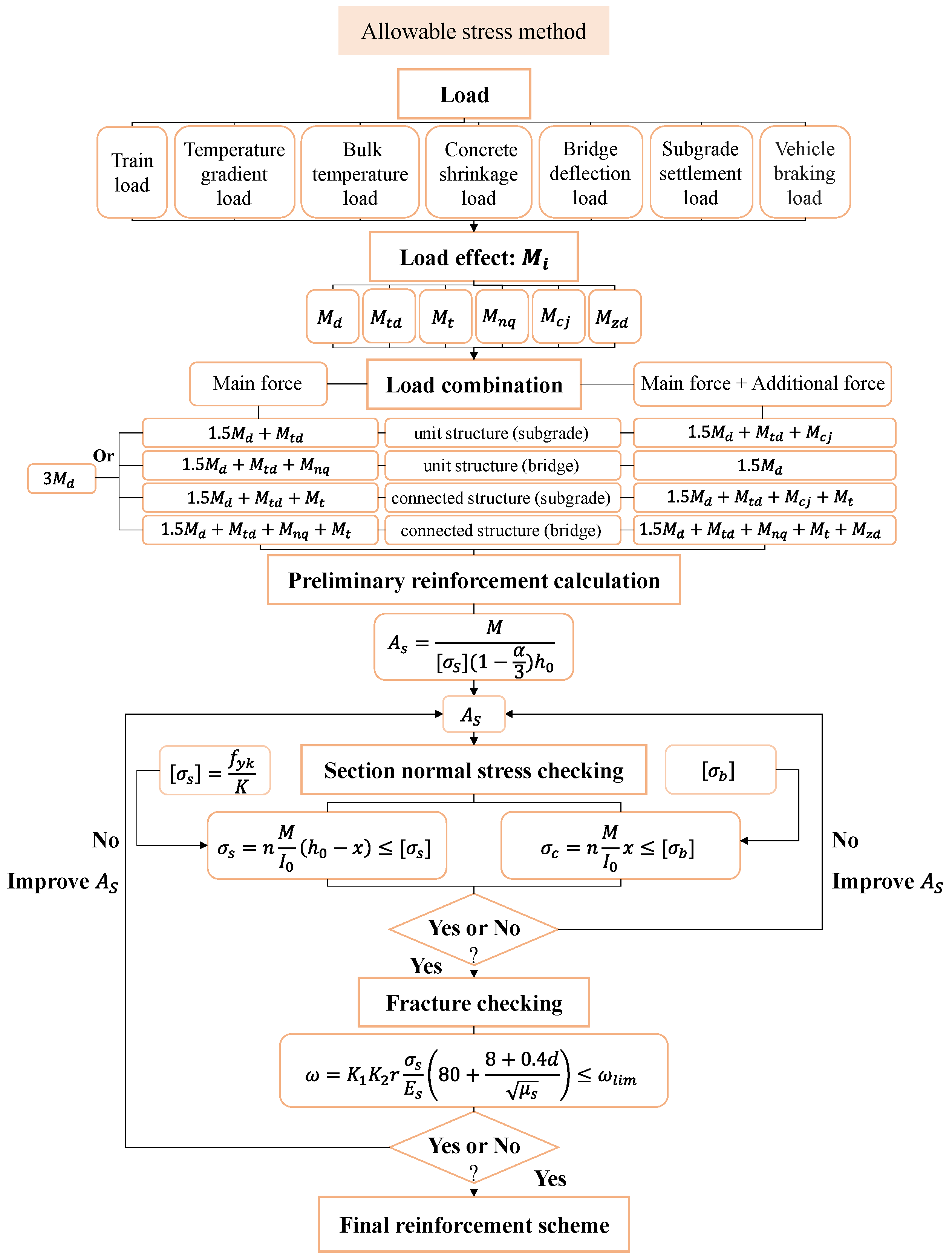
The ASM is based on the elastic theory. The calculation principle is that the stress at the most unfavorable position of the structure should be no greater than the allowable stress of material. By adopting a single safety factor K [
19], the calculation is convenient. According to the Code for the Design of Railway Tracks (TB10082-2017) [
20], the main design process of the allowable stress method is shown in
Figure 2.
According to the specification [
20], the loads considered in the ASM include the train load, temperature gradient load, bulk temperature load, concrete shrinkage load (considered as temperature dropping), bridge defection load and subgrade settlement load.
- (1)
Train load
The loading mode is a single axle with two wheels, and the static wheel load is half of the axle load. For the ASM, according to the specification [
20], the train load adopts the design value, calculated as follows:
The design value of the vertical train load is expressed as:
where
is the vertical design load,
is the dynamic load coefficient, and
is the static wheel weight. And the value of
α is related to the axle weight and speed of the train according to the code [
20].
The design value of the lateral train load is as follows:
- (2)
Temperature gradient load
According to the code [
20], the value of the temperature gradient load is related to the slab thickness. For a thickness of 220 mm, the max temperature gradient is set as 90 °C/m and −45 °C/m, and the slab thickness correction coefficient
is adopted for others (for the thickness of 200 mm,
).
- (3)
Bulk temperature load
Generally, the maximum temperature can be determined according to the local temperature conditions.
- (4)
Concrete shrinkage load
Concrete shrinkage can be equivalently considered as a temperature drop of 10 °C for the track slab.
- (5)
Bridge defection load
According to the code [
20], the deflection shape is assumed as Formula (5):
The maximum curvature of the deformation curve is:
where
is the midspan deflection of bridge, and L is the bridge span.
- (6)
Subgrade settlement load
The shape of the subgrade settlement curve is determined using the formula
The maximum curvature of the deformation curve is:
where
is the settlement amplitude of subgrade, and
is the wavelength of the settlement.
- (7)
Vehicle braking load
The braking load is less likely to occur, so it is taken as an additional force. The formula is not specified, but some scholars calculate it by applying force equivalent to each fastener with the finite element method [
34].
Track structures will generate moment effects under different loads. In
Figure 2,
,
,
,
,
and
are design values of moment effects under train load, temperature gradient, bulk temperature (including concrete shrinkage load), bridge defection, subgrade settlement and vehicle braking load. The moment effect can be calculated with the formula in the specification or the finite element method (FEM).
Then, various load effects combine and determine the reinforcement of the structure. What is more, for diverse structures, the effect and influence of various loads are different, so different combinations are considered. For the unit structure, the bulk temperature change has little influence on track stress, so only the train load, temperature gradient and bridge defection or subgrade settlement are considered. For the longitudinally connected track structure, it is necessary to consider the bulk temperature and the concrete shrinkage load because the temperature stress is difficult to release and has great influence on the structure.
For the ASM, loads are classified into main force and additional force, and load combination includes two methods differentiated by considering additional force or not, each of which has a certain value of safety factor
. The train load effect is the most important in the main force, which multiplies by a greater factor, and the details are shown in
Figure 2.
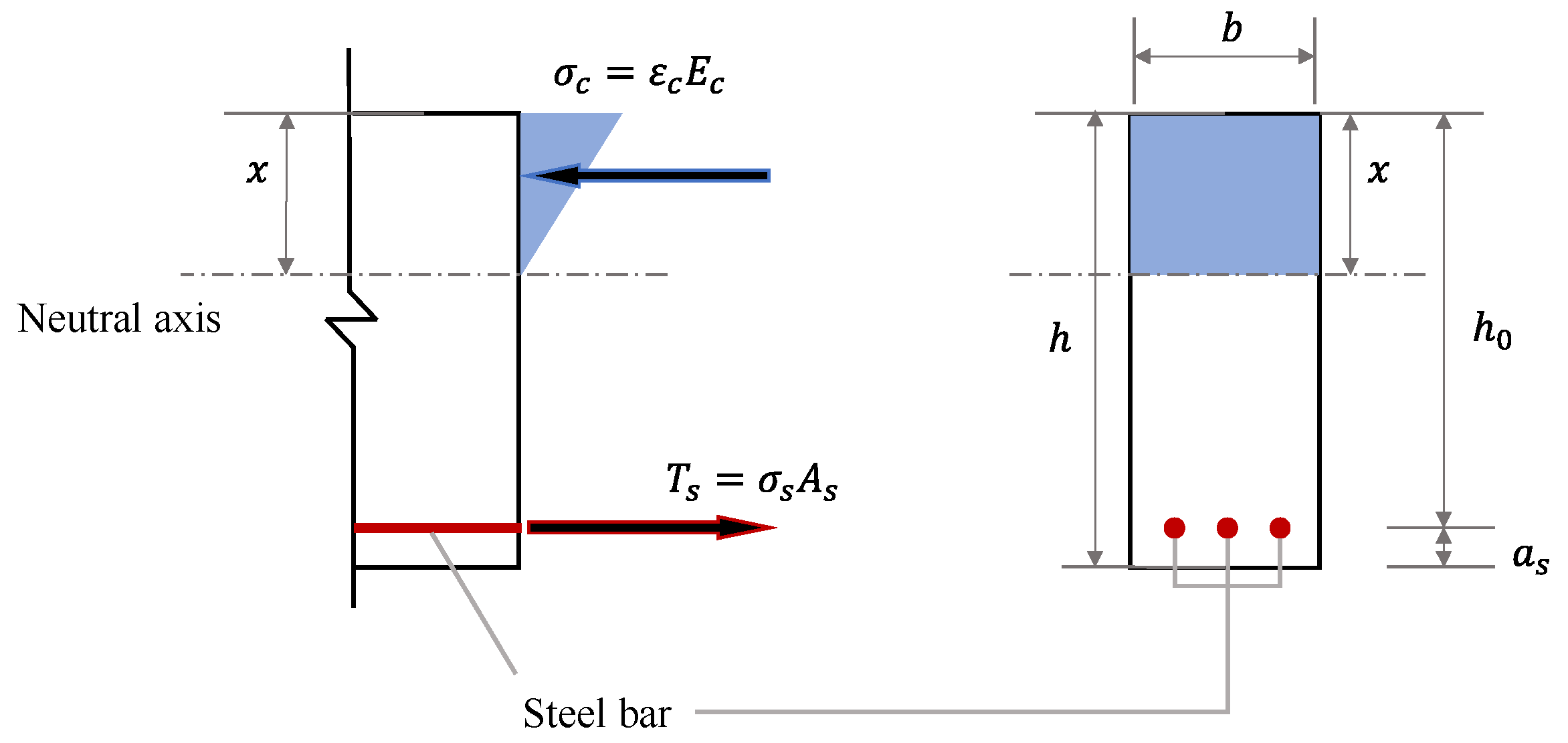
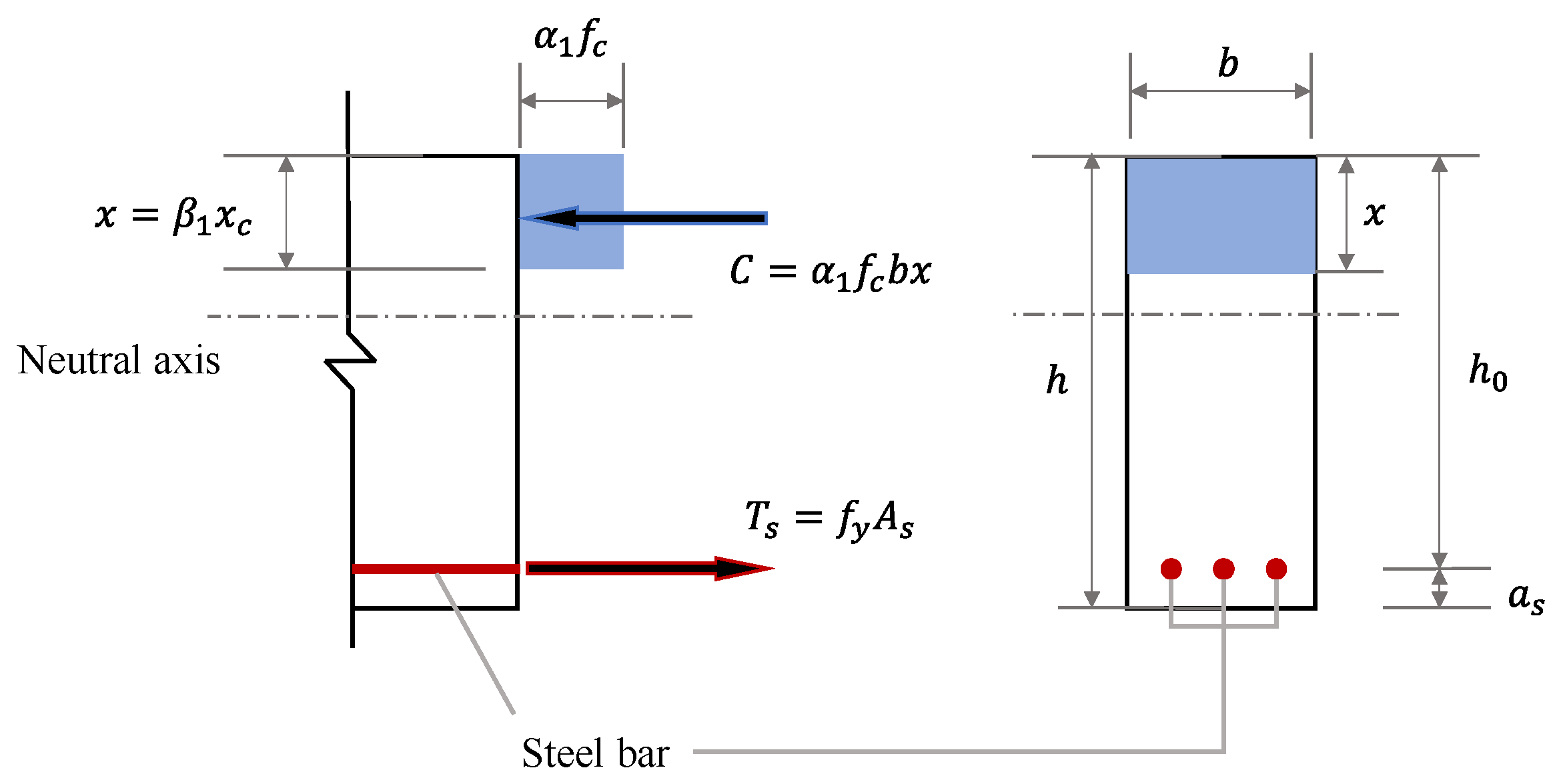
The reinforcement result is calculated according to the load combination effect. First, the cross-sectional area of the steel bar
As is preliminary calculated using the force balance formula, and the stress of steel bar should be no more than the allowable stress [
σs], which is determined by its tensile strength
fyk and the safety factor
. According to the stress distribution characteristics, the force balance diagram is shown in
Figure 3, and the relevant parameters are labeled in the diagram.
Then, the preliminary calculation results should be checked by the normal stress of the structure. The tensile stress of the steel bar
σs is less than the allowable
, and the compressive stress of concrete
σc is less than the allowable [
σb]. Formulas for stress checking are shown in
Figure 2. Finally, the reinforcement result must ensure that the crack width
ω is not greater than the maximum value
ωlim.
The final reinforcement scheme is obtained after meeting all checking conditions.
2.2. Limit State Method
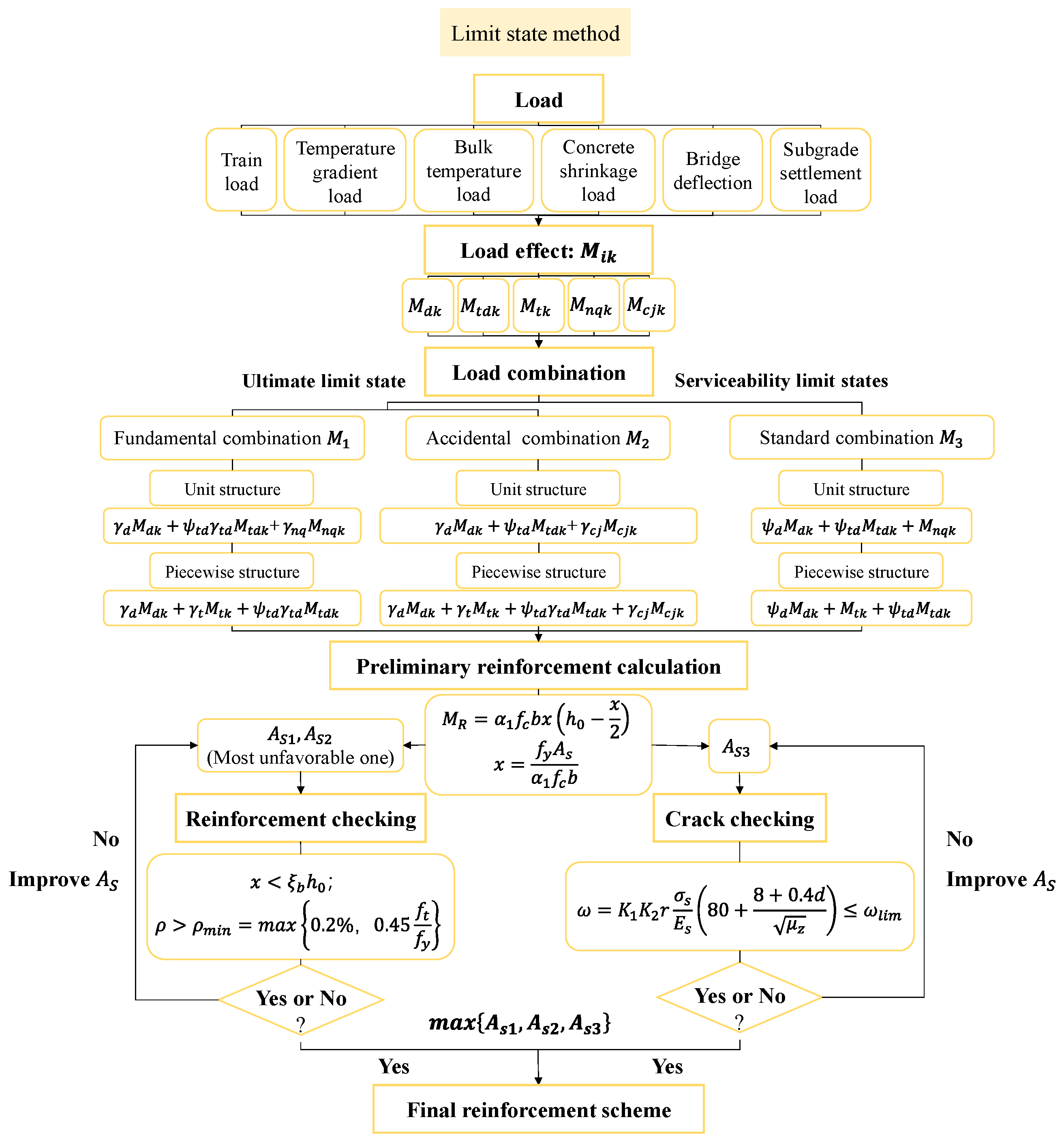
The LSM analyzes, evaluates and controls the structure based on its performance under the limit state. It takes the limit state that prevents the structure or sections from reaching the requirements of certain functions as the basis and can ensure the safety and reliability of the structure under extreme loads and severe conditions. Theoretically, the LSM is more advanced than the ASM [
35]. According to the Code for the Design of Railway Tracks (Limit State Method) (Q/CR 9130-2018) [
31], the main process of the limit state method is shown in
Figure 4.
According to the specification [
31], the loads considered in the LSM are similar to those of the ASM.
The determination of the temperature gradient load, bulk temperature load, bridge defection load and subgrade settlement load of the LSM are same as those of the ASM. However, the train loads of the two methods have some differences. For the LSM, according to the specification [
31], the vertical load and lateral load adopt the standard value. The calculation method is as follows:
The standard value of the vertical train load is as follows:
which is double the static wheel weight in any working condition.
The standard value of the lateral train load is expressed as:
In
Figure 4,
,
,
,
and
are the standard values of moment effects under train load, temperature gradient load, bulk temperature load, bridge defection load and subgrade settlement load, which can also be calculated using the formula or FEM.
For unit structures and piecewise structures, the combination of moment effect
is calculated as a basis of reinforcement, and the combination methods include fundamental combination, accidental combination and standard combination. But for longitudinal connected structure, the load effect is considered in the form of axial force
with a different calculation system, which is not introduced in this paper, and more details can be found in the specification [
31].
Similar to the ASM, for unit structures, the train load, temperature gradient load, bridge defection load or subgrade settlement load are considered. For piecewise structures, the bulk temperature load (including concrete shrinkage load) should also be considered.
Different from the ASM, which uses the safety factor
as the only and unified factor to create safety allowance, the LSM uses the partial coefficient
γ and load combination factor
ψ in effect combination to consider the structural failure probability under different limit states. The combination formulas are shown in
Figure 4, and the specific parameter values are defined in the specification [
31].
The calculation for the reinforcement of the limit state depends on the principle that combination effect
should be no more than the resistance of structure
MR, which is mainly afforded by the steel bar in tension and the concrete in compression. Different from the ASM, when calculating
, the reinforced concrete material is converted to homogeneous concrete material using an equivalent method, and the height of the compression zone after conversion is
. The meanings of other parameters are shown in
Figure 5. According to force balance, the cross-sectional area of the steel bar
As is preliminary calculated.
When calculating the reinforcement according to the LSM, the effect combination should take the larger value between the fundamental combination and the accidental combination, and the result should be verified by the maximum height of compression zone and the minimum reinforcement ratio. What is more, it is necessary to check the crack limit using the standard combination effect. Finally, the result that meets all these criteria will be the final reinforcement scheme.
3. Case and Calculation Model
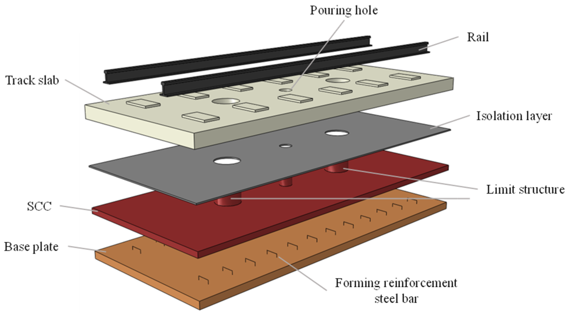
To deeply study the difference between the LSM and the ASM, we take a new track structure as an example. The theoretical analysis of the track slab under the two design methods is carried out. The selected slab is a new type of prefabricated track slab applied to a railway express line, with the highest design speed of 160~200 km/h, which is faster than the design speed of general urban express lines but lower than that of high-speed railways. It consists of rail, fasteners, a prefabricated slab, isolation layer, self-compacting concrete (SCC) adjustment layer, reinforced concrete base, double-hole limit structure and other parts. The SCC is cast together with the base plate through reinforcement, and the double-hole limit structure provides interlayer confinement for the track slab. The structure diagram of the prefabricated track is shown in
Figure 6.
3.1. Finite Element Model of Track Structure on Bridge
Under the action of a train load and temperature load, the prefabricated track slab is prone to cracking and arching. With the foundation of a bridge, the bridge deflection will also cause the deformation of the track, which is more unfavorable to the stress of the track structure. Therefore, a static finite element model of the track on the bridge foundation is established, as shown in
Figure 7. To eliminate the influence of boundary conditions, the length of the model is 97.1 m, a three-span bridge. Six track slabs are laid in each span of a simply supported beam. Considering the most unfavorable situation, the N5520 track slab in the middle of the second span is mainly analyzed.
The CHN60 rail is simulated by solid elements. The fastener is simulated using a 3-D spring element, which is endowed with vertical and lateral stiffness and longitudinal resistance. The track slab, SCC, base plate and bridge beam are all simulated using solid elements according to the actual size. The main structure dimensions and material parameters of the model are summarized, as shown in
Table 1.
In terms of boundary conditions, the terminal of the rail is considered a longitudinal constraint. One end of the bridge support is fixed, and another is hinged. In terms of contact relation, the rail relates to the track slab via fasteners. The contacts of the track slab–SCC, track slab–limiting pile and base plate–bridge are set as surface contacts. The SCC relates to the limiting pile and the base plate via binding constraints.
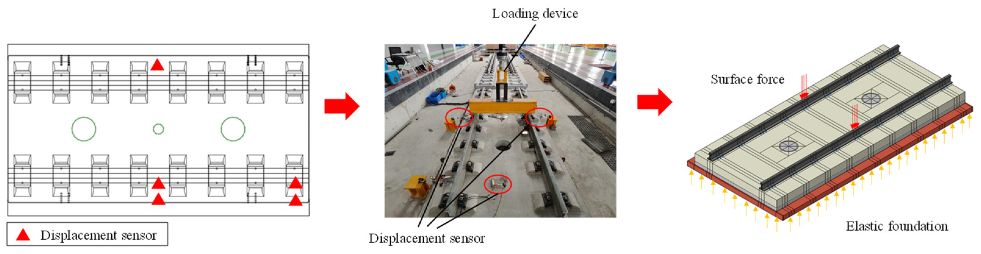
3.2. Model Validation
To verify the correctness of the finite element model, a static load test was carried out. By adding a gradually increasing load in the middle of a single track structure, which is placed on the ground, the vertical displacement of the track structure was tested and compared with the loading calculation results of the simulation model. The layout of the measurement points and the loading diagram is shown in
Figure 8, and the validation result is shown in
Figure 9.
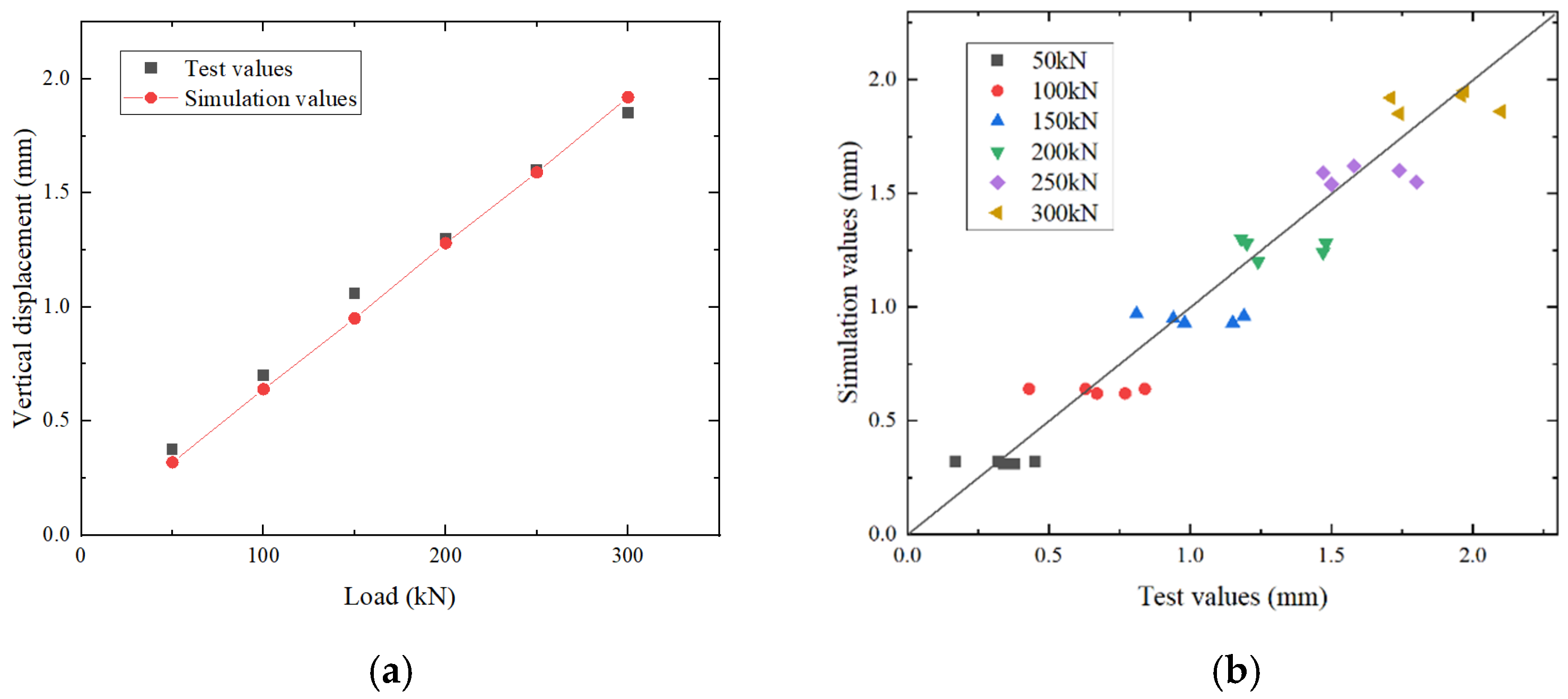
According to the calculation results, the load–vertical displacement relationship is analyzed. It is shown in
Figure 9 (a) that the variation trend and values of vertical displacement with the load are basically the same between the test and simulation. What is more, it can be seen from (b) that the test and simulation values at different measurement points are basically corresponding and distributed around the 45° contour. The simulation results fit well with the test results, and the error is small, proving the reliability of the model.
3.3. Working Conditions
When the prefabricated track slab is a unit structure and the foundation is a bridge, the calculating loads mainly include the train load, temperature gradient and bridge deflection. For the LSM, the fundamental combination and coincidence combination are used to check the normal stress of the section, and the standard combination is used to check the crack. As for the ASM, only the main forces are considered in the load combination. To explore the influence of different load parameters on the reinforcement results, it is necessary to set a series of working conditions when determining the load values.
- (1)
Train load
According to the requirements of the Code for the Design of Intercity Railways (TB10623-2014) [
36], different train axle loads and speeds will affect the values of the train load, which will also affect the reinforcement results. Therefore, three working conditions are adopted, including a passenger and freight railway with a design speed of 200 km/h (D1), an intercity railway with a design speed of 160 km/h (D2) and an intercity railway with a design speed of 200 km/h (D3). Under different working conditions, the train loads of the LSM and the ASM are shown in
Table 2.
In simulation analysis, the vertical train load is loaded on the center of N5520 track slab in the middle of the bridge, which is the most unfavorable position.
- (2)
Temperature gradient load
The track slab is affected by continuous solar radiation, so it is necessary to consider the temperature load. Because the new prefabricated track slab is a unit structure, only the temperature gradient is considered.
In consideration of extreme heat conditions, the vertical positive temperature gradient of the track slab is set from
to
; the negative temperature gradient is set from
to
, shown in
Table 3.
- (3)
Bridge deflection load
It is also necessary to consider the influence of bridge deflection on the track structure. The foundation is a 32 m double-line simply supported box-girder bridge, and the maximum rotation angle is 1/1000.
4. Results and Analysis
Based on the established model, the load effects of the ASM and the LSM are analyzed. Subsequently, the reinforcement laws are explored, and the influence of important parameters is analyzed.
4.1. Load Effect Analysis
For the two design methods, the train load, temperature gradient and bridge deflection load are considered. The bending moments under different loads are calculated.
4.1.1. Train Load Effect
For a unit track slab, considering the vertical and lateral train loads, which have great influence on the stress of track structure, and ignoring the traction and braking load, the structural mechanical response of track is analyzed.
- (1)
Vertical train load
The vertical train load causes longitudinal and lateral bending of the track slab. Based on the finite element model, the load effects of the track slab under different working conditions are analyzed. Supposing that the moment is positive when the undersurface of the slab is under tension, the moment effect in different positions of the mid-span track slab under D1 is shown in
Figure 10. The maximum longitudinal and lateral positive moment occurs at the loading position.
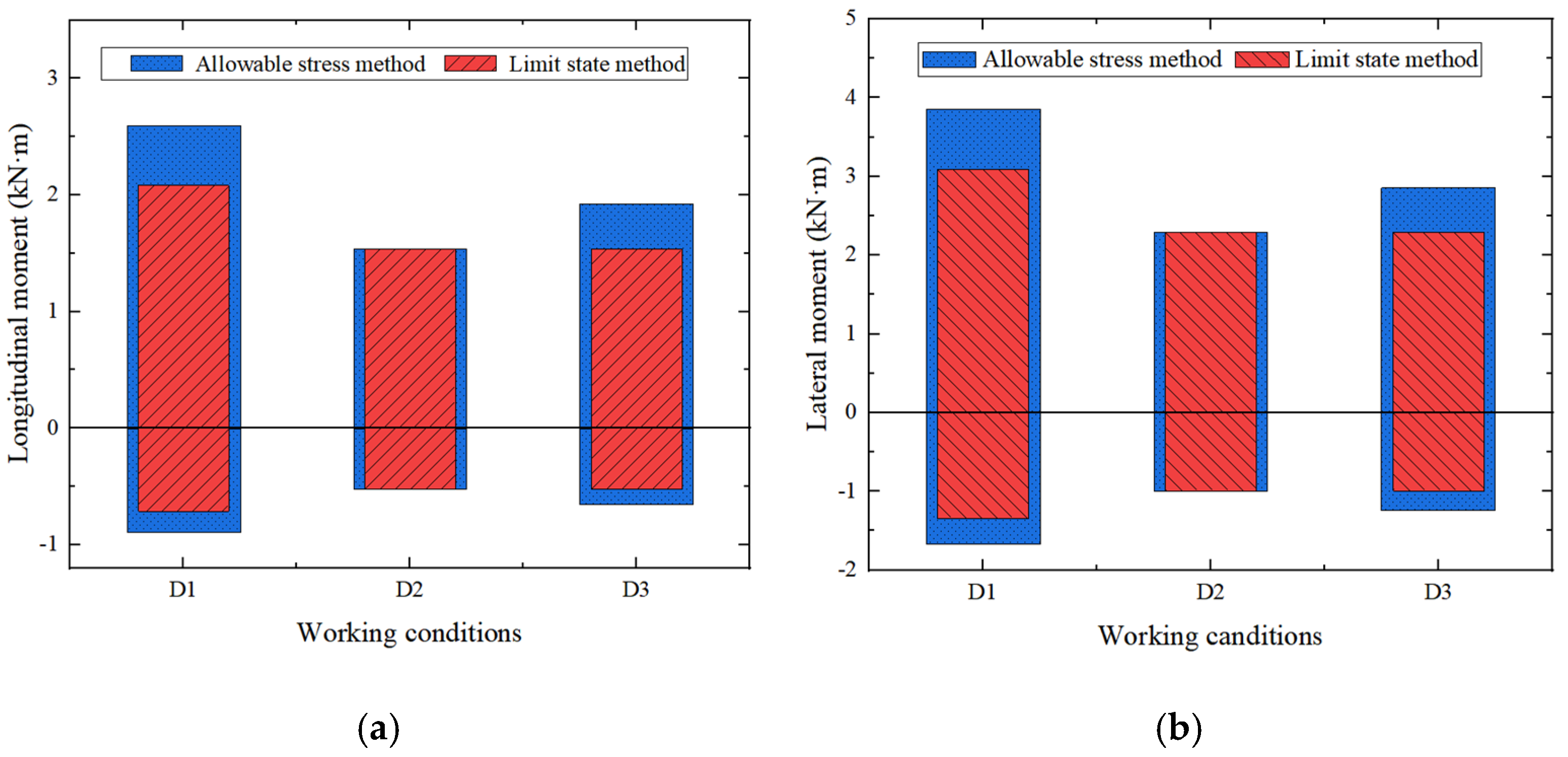
In the longitudinal direction, the maximum moment is at the loading position, and the moment reduces to 0 at the end of track slab. In the lateral direction, the maximum moment also appears at the loading position. The calculation results of the two methods are compared in
Figure 11.
The train load effects under various working conditions are different. In D1, the moment is the largest due to the largest design of the axle load and design speed of the train, while in D2, it is the smallest. Therefore, the working conditions have a great influence on the train load effects. In addition, it can be seen from
Figure 11 that under all three conditions, the train load effects calculated according to the ASM are greater than or equal to these calculated according to the LSM, and there is an obvious surplus. In D1 and D3, the dynamic load coefficients are different between the two methods, so their load effects also show a difference. The dynamic load coefficient of the LSM in D1 is smaller than that of the ASM by 20%, and the load effects of the two methods have a difference approaching 20%, which means that the dynamic load coefficient is the major factor in influence the effect under train load.
- (2)
Lateral train load
Under the lateral train load, the lateral bending moment is the main effect. For the ASM and the LSM, the calculation method of the lateral moment is same:
The distance from the bottom of the track bed to the track surface ‘h’ is considered as 0.2 m. The maximum moments of the track slab under three working conditions are as shown in
Table 4.
4.1.2. Temperature Gradient Load Effect
Because the new prefabricated track slab is a unit slab, the load effect caused by a temperature rise and drop (expansion and contraction of track slab and temperature stress) is far less than that caused by the temperature gradient (arch or warping of track slab), so only the effect of the temperature gradient is considered.
The calculation of the temperature gradient load effect shows no great difference between the ASM and the LSM. According to the specification [
20,
31], under the temperature gradient
, the bending effect is:
The positive temperature gradient is 90 °C/m, and the negative temperature gradient is −45 °C/m. For the ASM, when the temperature gradient effect is combined with other effects, the temperature gradient is half of the maximum. The longitudinal and lateral moments of the track slab are shown in
Table 5.
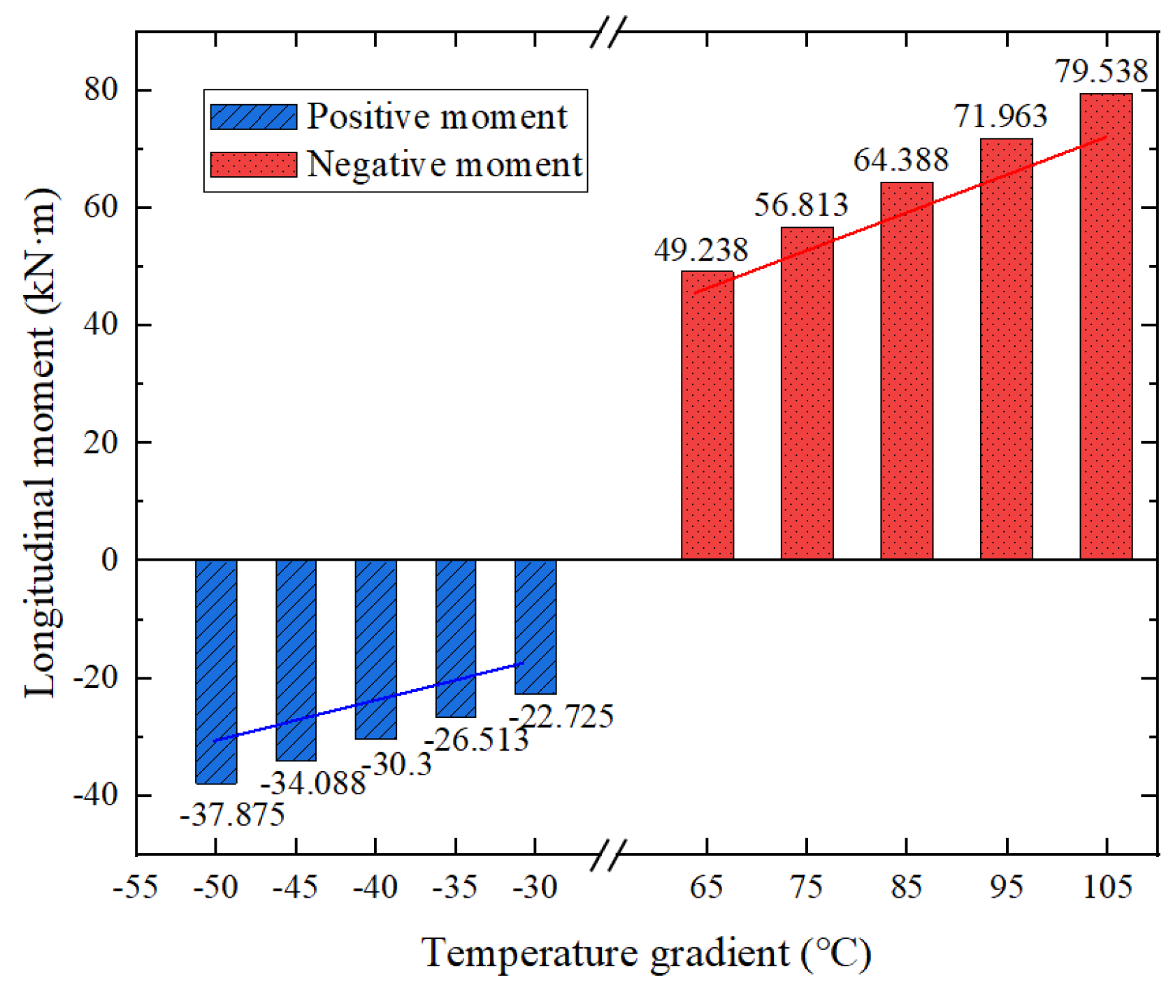
Furthermore, the effect under different temperature gradients is calculated, as shown in
Figure 12.
It shows that the track slab will generate a positive moment under a positive temperature gradient and a negative moment under a negative temperature gradient due to the limitations of boundary conditions, and the track plate will generate a positive bending moment under a positive temperature gradient and a negative bending moment under a negative temperature gradient. The greater the temperature gradient is, the greater the moment effects are, and the relationship is approximately linear.
4.1.3. Bridge Deflection Load Effect
Bridge deflection has a great influence on the stress and deformation of the track on the bridge, so it is necessary to consider the bridge deflection effect.
The calculation method for the bridge deflection load effect of the ASM and the LSM is basically the same. It mainly causes longitudinal moments of track slabs. Selecting the middle span of the bridge as object, the maximum moment is calculated according to Formula (9):
The maximum longitudinal moments are 5.551 kN·m/m.
4.2. Load Combination Analysis
Based on the analysis results of the load effect, the moment values under different load combinations of the ASM and the LSM are calculated. The specific partial coefficients of different load combinations are shown in
Table 6.
Furthermore, the combination values of moment effect are shown in
Table 7.
According to the calculation results, the combination effects of the LSM are smaller than those of the ASM in all three working conditions. It shows that the calculation of the ASM is more conservative and safer but may cause the waste of materials. However, the difference between the two methods is not so significant because the coefficient values of the two methods are relatively similar.
Under different working conditions, the combination values are also close. On the one hand, the train load effects of the track slab are smaller than other loads; on the other hand, the partial coefficients of the train load in different working conditions are close, so working conditions have little influence on the combination values of load effects.
For longitudinal effects, the value of coincidence combination of the LSM is the smallest; for lateral effects, the value of standard combination of the LSM is the smallest. This is because the bridge deflection mainly causes longitudinal bending moments. If the bridge deflection effect is not considered or the partial coefficient of it is small in the combination calculation, the combination values will be greatly influenced.
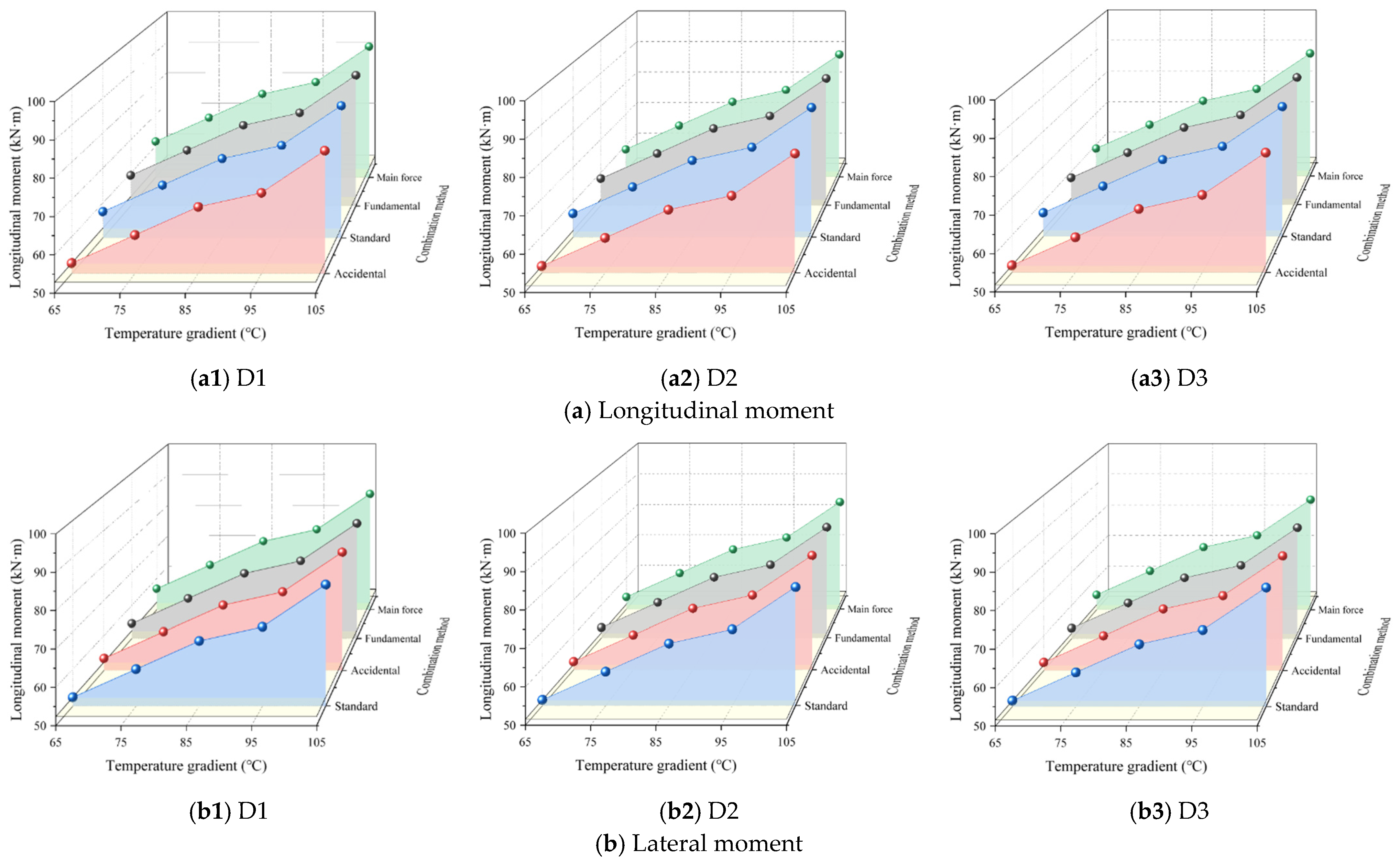
Furthermore, considering that the effect under a temperature gradient load is larger than that under other load, which may have a great influence on the combination values, a series of temperature gradients are set up to analyze the influence rules, and the results are shown in
Figure 13.
It is shown in
Figure 13 that with the increase in the temperature gradient, the effect values with different combination methods all have approximate linear growths, and the growth rates are nearly same. When the temperature gradient is 105 °C, the main force combination values are over 90 kN·m in all three working conditions, with an increase of nearly 50%, which means that the temperature gradient has a great influence on the effect combination values. This also indicates that in regions with significant temperature fluctuations, the bending moment and deformation of the track structure are mainly controlled by the temperature load.
4.3. Analysis of Calculation Results of Reinforcement
Track slabs are usually compressed on one side and tensioned on the other side when subjected to loads. Due to the inferior tensile properties of concrete material, reinforcement on the tension side is necessary to strengthen the track slab. To investigate the discrepancies of the ASM and the LSM in structure design, the reinforcement under the two methods is calculated, and the influence rules of different parameters are analyzed.
The new prefabricated track slab is reinforced by HRB400 steel bars with a diameter of 8 mm in the longitudinal direction and 12 mm in the lateral direction. According to the Code for the Design of Concrete Structures (GB 50010-2010) [
37], for the prefabricated slab, the height of the relative limit compression zone
is 0.4992. To ensure that the thickness of the protective layer is not less than 35 mm, the distance from the tensile steel bar to the tensile edge
is 39 mm longitudinally and 49 mm laterally. According to the requirement of a minimum reinforcement ratio, the area of the section shall not be less than 579.6 mm
2 longitudinally and 1107.6 mm
2 laterally. In the process of reinforcement design, to ensure that the cracking of the track slab is less than 0.2 mm, the standard combination of the LSM and the main force combination of the ASM play decisive roles. The reinforcement results are shown in
Figure 14.
The reinforcement ratio of the ASM is greater than that of the LSM in all working conditions. In words, the ASM is more reliable with a greater margin, but the LSM is more efficient and material saving. The LSM can reduce the reinforcement by about 6.5% compared with the ASM.
The reinforcement ratios under different working conditions have minor differences, which shows that the influence of the train load is relatively small. However, under the same working conditions, the reinforcement ratios increase obviously with the increase in temperature gradient, which is the main control factor. What is more, the greater the temperature gradient is, the smaller the difference between the two methods is. It is because the temperature gradient load effects of the two methods have similar values. In fact, the determination of the specific partial coefficients of the LSM refers to the design experience of the ASM to some extent, which causes the minor difference between the two methods.
Therefore, the LSM can save more materials, but the optimization effect is relatively limited due to the coefficient value determination method of the current LSM specification in China. In particular, in regions with significant temperature fluctuations, the similar temperature load coefficients make the advantage of the LSM even less obvious.
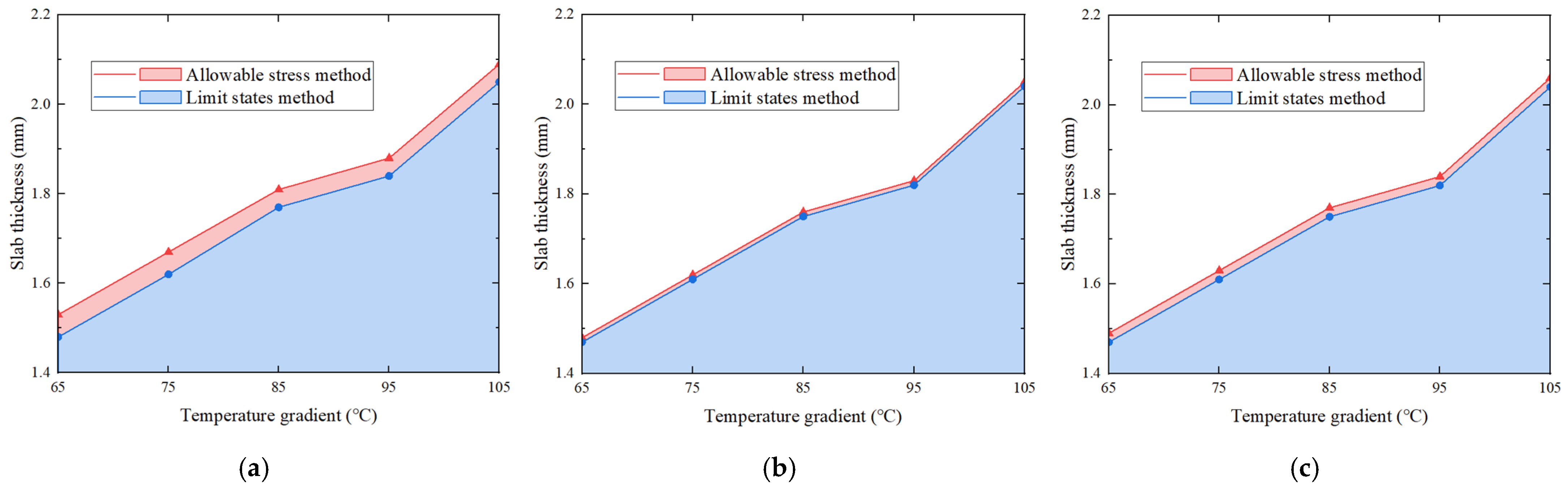
To further investigate the optimization effect of the LSM compared to the ASM in track design, the dimensions of the track structure are adjusted under the condition of a fixed amount of reinforcement according to the two methods, and the required thickness is calculated, as shown in
Figure 15.
As shown in
Figure 15, under a certain quantity of reinforcement, the thickness of the track slab is influenced by temperature, too. With the increase in temperature gradient, the required thickness escalates. When the temperature gradient rises from 65 °C to 105 °C, the slab thickness grows by nearly 40%. In addition, the required thickness calculated according to the LSM is consistently less than that calculated according to the ASM. In D1, the maximum disparity in the required thickness between the two methods amounts to 3.4%, while in D2, it is only 0.5%. Similarly, due to the influence of parameter values, the difference in calculation results between the two methods is minor, and the optimization effectiveness of the LSM still requires further enhancement.
Theoretically speaking, the LSM can achieve a more efficient and scientific structural design than the ASM by rationally allocating partial coefficients to consider the failure probability. The increasingly diversified demands of track structure design in China require that the LSM can adequately consider the reliability of different structures and give full play to the material properties. However, the calibration reliance on the older ASM coefficient values causes that the current LSM specification in China cannot fully leveraged the inherent theoretical advantages of probability-based design in international standards and has limited optimization effect. Therefore, further research is needed to discuss the rationality of coefficient values. In addition, future design optimization efforts within the LSM framework should prioritize accurately modeling and accounting for temperature effects, which have a more significant influence on force and reinforcement of the track structure, especially in areas with large temperature variations.
5. Conclusions
Based on the methodological analysis of the LSM and the ASM, the reinforcement and structural design of a prefabricated slab track are analyzed and computed by combining finite element analysis and formula calculation. Simultaneously, the differences between the two methods and the influencing factors are explored. Furthermore, the material-saving effect and control parameters of the LSM in structural design are studied, which engendered the future development directions and suggestions for optimizing the structural design method. The main conclusions are as follows:
- (1)
For a single load, the load values of the ASM and LSM are basically similar, but for train loads, the value of the ASM is more conservative than the LSM. Therefore, the vertical train load effect of the ASM has a significant margin compared with LSM and is greatly affected by the working conditions. There is not much difference in the effects of other loads under the two design methods.
- (2)
In terms of combination values of the load effect, the main force combination of the ASM is larger than that of different combination methods of the LSM, in which the fundamental combination plays a control role. Among various factors, working conditions have little influence on the combination values of effects. With the increase in the temperature gradient, the combination values under the two design methods all grow linearly, which means that the temperature gradient plays an important role. In areas with large temperature fluctuations, the temperature load will be the main controlling factor of structural effects.
- (3)
In terms of reinforcement, the calculation processes are different between the two design methods. For the ASM, stress and cracking are checked according to the main force combination in calculation of the reinforcement ratio. For the LSM, the stress is calculated according to the fundamental combination or accidental combination, and cracking is checked according to the standard combination. The results show that reinforcement according to the LSM can save materials on the premise of meeting the specification requirements, by nearly 6.5%. The results are mainly controlled by the temperature gradient. Similarly, under a certain amount of reinforcement, the slab thickness of the LSM can be approximately 3.4% less than that of the ASM, which is also predominantly controlled by the temperature gradient. However, because the partial coefficients of the current LSM specification in China are calibrated according to the ASM, the optimization effect of the LSM in track design is not so significant, and theoretical advantages of probability-based design of the LSM in international standards cannot be fully leveraged.
- (4)
The rational coefficient values of the LSM remain to be studied further to meet the future requirements of structural design. In particular, appropriately accounting for temperature effects is vital because of its significant influence on track structure design under large temperature variations compared to other factors.
Since 2011, railway track design in China has transitioned from the ASM to the LSM, and a series of scientific research projects have been carried out. In 2018, the Code for the Design of Railway Tracks (Limit State Method) (Q/CR 9130-2018) [
31] was published. During the formal transition process, due to limited time, basic data, working conditions and other resource, in-depth research on the expression and important design parameters such as the partial coefficients was lacking. In particular, the values of correlation coefficients were calibrated based on the ASM, which caused a restricted optimization effect. The LSM has great room for improvement in design redundancy reduction and material efficient utilization using scientific parameter values. To further enhance the technical and economic benefits of the LSM, long-term collection, statistics and analysis of structural effects, resistances and material performance are still needed to provide support for optimizing the design parameters of the LSM.


