Article

Proof-of-Concept of a Monopulse Antenna Architecture Enabling Radar Sensors in Unmanned Aircraft Collision Avoidance Systems for UAS in U-Space Airspaces

by
Javier Ruiz Alapont
1,
Miguel Ferrando-Bataller
2 and
Juan V. Balbastre
1,*
1
ITACA Research Institute, Universitat Politècnica de València, Camino de Vera s/n, 46022 Valencia, Spain
2
ITEAM Research Institute, Universitat Politècnica de València, Camino de Vera s/n, 46022 Valencia, Spain
*
Author to whom correspondence should be addressed.
Appl. Sci. 2025, 15(10), 5618; https://doi.org/10.3390/app15105618 (registering DOI)
Submission received: 18 March 2025 / Revised: 4 May 2025 / Accepted: 12 May 2025 / Published: 17 May 2025
(This article belongs to the Special Issue Recent Advances and Applications of Autonomous Aerial Vehicles)

Abstract

:

Featured Application

The antenna presented in this paper has been designed for integration into collision avoidance systems for small, unmanned aircraft.

Abstract

In this paper, we propose and prove an innovative radar antenna concept suitable for collision avoidance (CA) systems installed onboard small, unmanned aircraft (UA). The proposed architecture provides 360° monopulse coverage around the host platform, enabling the detection and accurate position estimation of airborne, non-cooperative intruders using lightweight, low-profile antennas. These antennas can be manufactured using low-cost 3D printing techniques and are easily integrated into the UA airframe without compromising airworthiness. We present a Detect and Avoid (DAA) concept of operations (ConOps) aligned with the SESAR U-space ConOps, Edition 4. In this ConOps, the Remain Well Clear (RWC) and CA functions are treated separately: RWC is the responsibility of ground-based U-space services, while CA is implemented as an airborne safety net using onboard equipment. Based on this framework, we derive operation-centric design requirements and propose an antenna architecture based on a fixed circular array of sector waveguides. This solution overcomes key limitations of existing radar antennas for UAS CA systems by providing a wider field of view, higher power handling, and reduced mechanical complexity and cost. We prove the proposed concept through a combination of simulations and measurements conducted in an anechoic chamber using a 24 GHz prototype.

1. Introduction

Unmanned Aircraft Systems (UAS) are defined by the International Civil Aviation Organization (ICAO) as ‘aircraft and their associated elements which are operated with no pilot on board’ [1]. This term refers to either a Remotely Piloted Aircraft System (RPAS) or a fully autonomous unmanned aircraft (i.e., one that operates without any human intervention during flight). Throughout this paper, we use the term Unmanned Aircraft (UA) specifically to denote the airborne component of a UAS. Although UAS have been employed in military operations for over a century—for example, during World War I [2] and the Vietnam War [3]—widespread interest in their civil applications did not emerge until the early 21st century. Today, there is substantial anticipation surrounding a wide range of professional uses for UAS across various sectors—including urban mobility, delivery services, public safety and security, entertainment, agriculture, infrastructure inspection, and recreational activities. At the European Union (EU) level alone, the projected market demand is valued at several billion euros annually over the coming decades, with expectations of creating more than 400,000 highly skilled jobs by 2050 [4]. A large share of this market involves operations within what is commonly referred to as Very Low Level (VLL) airspace, typically located over densely populated urban and industrial areas. According to [5], VLL is defined as the airspace below the minimum altitude specified for Visual Flight Rules (VFR) operations. However, VFR operations may still occur within VLL airspace, provided they are authorized by the competent authority.
While citizens are drawn to the anticipated economic and societal benefits of UAS operations, they also expect these operations to be as safe as traditional manned aviation and to pose no negative impact on the safety of crewed air traffic (see, for instance, [6]). In response, competent authorities worldwide have implemented measures to ensure that the safety of UAS operations is commensurate with the risks they pose. One such measure is Commission Implementing Regulation (EU) 2019/947 [7] (hereinafter referred to as Reg. 947), which establishes three risk-based categories of UAS operations: open, specific, and certified, representing increasing levels of operational risk. This regulation has been in force in EU Member States since July 2020 and is also applicable in other countries within the European Economic Area (EEA).
Depending on the operational risk, UAS operators may be required by the competent authorities to implement specific mitigation measures. As a matter of fact, in the EU, UAS operators must conduct a safety assessment using the Specific Operations Risk Assessment (SORA) methodology [8] for operations that fall under the specific category, as defined in Reg. 947. According to SORA, operators are required to assign ground and air risk classes—referred to as GRC and ARC, respectively—based on the estimated level of risk [8]. Regarding the air risk, operators must apply mitigation measures to reduce the risk to acceptable levels unless the operation is classified under the lowest risk category (ARC-a). As part of these mitigation measures, operators may be required by the competent authority to employ Detect and Avoid (DAA) systems, with performance levels appropriate to the assessed risk. Although regulations for UAS operating in the certified category are still under development, DAA capabilities have already been identified as a key enabler for such operations, particularly in urban environments [9].
Detect and Avoid (DAA) comprises two functions that address the second and third layers of conflict management—namely, separation provision or Remain Well Clear (RWC), and Collision Avoidance (CA), respectively—according to [10,11]. Currently, two parallel initiatives are underway to define the specifications for DAA systems. On one hand, the Radio Technical Commission for Aeronautics (RTCA) has developed a Minimum Operational Performance Standard (MOPS) for the Airborne Collision Avoidance System sXu (ACAS sXu) [12], also known as RTCA DO-396. This standard specifies the requirements for systems to be installed on small, unmanned aircraft (sUA) with a wingspan of less than 25 feet with the goal of assisting remote pilots in avoiding collisions with a variety of intruders, whether manned or unmanned, and whether cooperative or non-cooperative—referred to as the ownship. Note that the term sUA comes from DO-396 and should not be confused with other similar weight-based definitions commonly used in the literature, such as the classification of small UAS with a maximum take-off weight below 55 pounds.
On the other hand, the European Organisation for Civil Aviation Equipment (EUROCAE) has developed an Operational Services and Environment Description (OSED) for DAA in Very Low-Level (VLL) operations, referred to as EUROCAE ED-267 [5]. This OSED defines a system designed to protect ownships operating in the specific category (as per Reg. 947) from intruders that meet the e-conspicuity requirement set forth in Commission Implementing Regulation (EU) 2021/666 [13] (hereinafter Reg. 666). Additionally, RTCA Special Committee (SC) 147 is developing the ACAS Xr concept, which is tailored to the specific characteristics of rotorcraft, including those intended for Urban Air Mobility (UAM) and Advanced Air Mobility (AAM) operations [14]. The system in DO-396 does not separate the RWC and CA functions but instead provides a single layer of warning alerts and directive guidance, based on protection volumes tailored to the intruder type. In contrast, ED-267 defines two distinct functions: RWC, which can be provided by either onboard or ground-based systems, and CA, which is handled exclusively by onboard equipment.
In parallel, the concept of Unmanned Aircraft Systems (UAS) Traffic Management (UTM) emerged in the mid-2010s as “a specific aspect of air traffic management that safely, economically, and efficiently manages UAS operations through the provision of facilities and a seamless set of services, in collaboration with all parties, involving both airborne and ground-based functions” according to the International Civil Aviation Organization (ICAO) definition in [15]. Based on ICAO’s UTM framework, several concepts of operations (ConOps) for providing UTM services have been developed worldwide (e.g., [16,17]). In the EU, the regional implementation of the UTM concept is known as U-space, which is being developed by the SESAR Joint Undertaking (JU), under the appointment of the European Commission, through the CORUS and CO-RUS-XUAM research projects. These efforts led to the publication of the latest version of the U-space ConOps in 2023 [18]
Based on the U-space ConOps, the European Commission has established a comprehensive regulatory framework that requires UAS operators to use certain foundational U-space services (U1), such as e-registration and e-identification [19], along with an airborne geo-awareness function, as stipulated by Commission Delegated Regulation (EU) 2019/945 [20], as amended by [21] (hereinafter referred to as Reg. 945). Furthermore, Commission Implementing Regulation (EU) 2021/664 (hereinafter Reg. 664) introduces the concept of U-space airspace as a designated UAS geographical zone (as per Art. 15 of Reg. 947) [22], where UAS operations can only occur with support from various U1 and U2 (initial) U-space services. These include at least network identification, flight authorization, geo-awareness, and traffic information, along with common information services that may be provided either by a federation of entities or a single designated organization (at the discretion of Member States). This regulation applies to all UAS operation categories defined in Reg. 947, with the exception of the lowest-risk open category and operations conducted under Instrument Flight Rules (IFR). Regarding manned aviation, aircraft receiving air traffic control instructions will be dynamically segregated from UAS operations via a Dynamic Airspace Reconfiguration mechanism, as outlined in [23,24]. Aircraft flying without air traffic control instructions may operate in U-space, provided they meet the e-conspicuity requirements of Reg. 666. The traffic information service provides UAS operators with a comprehensive view of traffic around the unmanned aircraft (UA) under their control. The ultimate responsibility for avoiding any collision hazard rests with the UAS operators, based on the information from the traffic information service. However, SESAR envisages that, as demand increases, a U3 (advanced) tactical conflict resolution (TCR) service will be introduced to support denser UAS operations by providing tactical separation [25]. In fact, SESAR is currently funding research projects, such as SPATIO [26], to deliver solutions for tactical conflict resolution with a high level of maturity by 2026. In line with this approach and considering the DAA system described in ED-267, we assume that the RWC function is provided by the U-space tactical conflict resolution service, while the CA function relies on airborne systems.
Both DO-396 and ED-267 recognise Air-to-Air Radar (ATAR) as a key enabling technology for DAA. The reference standard for DAA ATAR systems is RTCA DO-366, Minimum Operational Performance Standards (MOPS) for Air-to-Air Radar for Traffic Surveillance [27]. However, DO-396 notes that ATARs compliant with DO-366 may have size, weight, and power (SWaP) requirements that are incompatible with small drones. In addition to SWaP constraints, another significant difference between DO-396 ATAR systems and those used in larger UAS DAA systems, such as ACAS Xu, specified in EUROCAE ED-275 [28], is the radar field of view (FOV). While traditional systems typically offer a FOV of ±110° relative to the longitudinal axis of the UAS, DO-396 extends this to a full 360° coverage around the aircraft. Cost is also a critical factor: an ACAS Xu system compliant with ED-275 far exceeds the cost of a typical multirotor or small fixed-wing UAS.
Considering that antennas are major contributors to the size, weight, and cost of radar systems, the design of affordable, lightweight antennas with a low aerodynamic profile and 360° coverage around the host aircraft emerges as a clear research priority for enabling routine UAS operations using collision avoidance (CA) systems. In this paper, we propose and prove an innovative antenna architecture concept that addresses the identified research need.
The proposed architecture consists of a circular array of 2N sectorial cavity antennas that generate overlapping fixed radiation patterns, each shifted by π / N radians around the host aircraft. Each pair of adjacent sectors synthesises a monopulse radiation pattern pointing in a predefined direction (i.e., the sector boresight). We compute the off-boresight angle of a target (also referred to as a threat) by processing the sigma and delta channels of the monopulse patterns, as performed in State-of-the-Art Mode S radars [29]. The phase of the delta channel is then used to determine the sign of the off-boresight angle. In this way, we can accurately estimate the angular position of a threat across the full 360° range around the ownship, using compact radiating structures that are easily integrable into the UAS airframe. We have proved the proposed concept through a combination of simulations and experimental techniques. As outlined in Section 3.1, this solution offers advantages over current State-of-the-Art radar antennas used in UAS CA systems, which generally rely on either directive antennas with limited fields of view, printed antennas that cannot handle the power levels required to meet relevant standards, or rotating antennas that are mechanically complex and therefore expensive.
The remainder of the paper is organised as follows. In Section 2, we derive the antenna design requirements based on the intended operational context. In Section 3, we present a review of candidate architectures and formulate the proposed antenna concept, addressing the requirements established in Section 2 and supported by numerical analysis. In Section 4, we describe the approach used to prove the concept introduced in Section 3 and present the experimental results obtained using a prototype. In Section 5, we discuss the results presented in Section 4 to assess the level of technological maturity achieved by the proposed concept, summarise the conclusions of the work, and outline the next steps towards higher maturity levels.

2. Design Requirements

In this section, we derive design requirements for a CA radar antenna based on the system operational requirements and ATAR specifications in DO-366. Antennas are a crucial component of any radar system, as they impact detection range and angular accuracy. As assumed in Section 1, the CA function is triggered when the U-space tactical conflict resolution service fails, and the intruder breaches the RWC protection volume, provoking a loss of well clear (LoWC). In this case, the purpose of the CA function is to prevent the intruder from entering the NMAC volume. If the intruder penetrates the NMAC, providence will act as the last barrier before a mid-air collision (MAC) occurs.
In aviation, providence is defined as the conditional probability of a mid-air collision (MAC) occurring given that a near mid-air collision (NMAC) has taken place. In safety assessment, providence is usually considered as the last barrier once safety nets have failed.
Both the RTCA and EUROCAE approaches use a 2000 ft radius, 500 ft height cylinder centred at the ownship as the protection volume for RWC and a 500 ft radius, 200 ft height cylinder as the near mid-air collision (NMAC) volume for CA purposes, specifically for larger intruders (General Aviation (GA) or UAM/AAM aircraft), as proposed in [12]. Furthermore, DO-396 also proposes a small UA NMAC (sNMAC), consisting of a 50 ft radius, 30 ft height cylinder centred at the ownship, according to [30]. Based on this sNMAC, DO-396 proposes a cylindrical RWC volume with a 200 ft radius and 50 ft height for sUA. Therefore, the CA radar detection range should be 2000 ft (i.e., 619 m) for GA and UAM/AAM intruders, and 200 ft (61 m) for sUA.
DO-366 lists the frequency bands in which ATAR radar shall operate, specifically within the C, X, Ka, K, and Ku bands. On the other hand, the International Telecommunication Union (ITU) defines several Industrial, Scientific, and Medical (ISM) bands [31] across the electromagnetic spectrum to prevent high-power applications of electromagnetic energy, such as microwave heating or medical diathermy, from interfering with telecommunication systems. Furthermore, since these bands are unlicensed, certain telecommunication technologies, such as Bluetooth [32] and Wi-Fi [33], also make use of them.
In this paper, we use the 24 GHz ISM band, which is very close to the DO-366 K band (24.45–24.65 GHz). The ITU designates this ISM band, among other uses, for radiolocation. No authorisation is required to operate in this band, and there is no power limit. The small wavelength at this frequency (around 12.5 mm) enables the design of compact, lightweight antennas that can be integrated into sUAS without compromising their airworthiness. Since this is an ISM band, a wide range of Commercial-Off-The-Shelf (COTS) components is available, enabling low-cost radar system implementations. For example, the wideband solid-state power amplifier RFLU-PA18G26GF delivers a typical output of 54 dBm across the 18 GHz to 26.5 GHz range [34]. For the receiving chain, the ADF5904 receiver downconverter offers a noise figure of 10 dB at 24 GHz [35]. The main drawback of this frequency is its high free-space loss; however, due to the relatively short detection range, this does not compromise the feasibility of radar implementation in this band, as we prove at the end of this section. In contrast, designs at 24 GHz can be easily scaled to the DO-366 K band, if required.
With regard to the radar cross-section (σ) of the intruder, Annex E to DO-366 [12] provides a value of 5 dBsm for GA aircraft at 13 GHz, based on numerical analyses. Given that, according to [12], the radar cross-section remains nearly constant from the X to Ku bands, we assume that such targets operate in the optical region at these frequencies—i.e., σ is determined by the area subtended by the target at the radar location and does not depend on frequency [36]—and we use the same value in the K band. We also adopt this value for UAM/AAM aircraft, due to their apparent similarities with GA rotorcraft. For sUA, Semkin et al. present in [37] the results of a thorough experimental assessment of the radar cross-section of various platforms. Based on that study, we assume a radar cross-section of -16 dBsm at 24 GHz for sUAS.
We also assume that the radar operates as a continuous wave, linearly frequency-modulated (CW-LFM) system. Furthermore, we assume that the period of the modulating signal ( T m ) is set to ensure unambiguous detection range, i.e., T m = 4 · 10 7 R M A X / 3 , as given in [38]. Based on these assumptions, we use the CW-LFM radar equation from [38] to estimate the required antenna gain, considering that the transmitting and receiving antennas are identical.
G T / R = S N R 4 π 3 R M A X 4 k T o F L e x t L w i n P T T D W E L L λ 2 σ 1 / 2
where k = 1.35 · 10 23   J / K is Boltzmann’s constant, and T o = 290   K is the standard reference temperature.
We assume an SNR of 14.5 dB, corresponding to a 99% probability of detection and a 10 8 probability of false alarm with a matched receiver [36], and define L e x t = 2 α R , with α = 0.440   d B / N M [26]. T D W E L L denotes the time required to detect targets within a range bin using a Fast Fourier Transform (FFT) and digital filtering of the received signal. Assuming eight range bins and a Hamming window, we determine G T / R = 13   d B to detect both GA/UAM targets at 2000 ft and sUAS intruders at 200 ft, which are the respective RWC distances specified in DO-396.
Finally, from the assessments in Annex B of DO-396, we assume that the nominal FOV on the antenna shall be 360 ° in azimuth, whereas the coverage in elevation shall be as large as possible.

3. Formulation of a Concept of Radar Antennas for CA Systems

In this section, we formulate a concept of radar antennas intended for use in CA systems onboard sUA, in accordance with the requirements set out in Section 2. First, in Section 3.1, we present a review of the literature on radar antennas for CA systems, which shows that existing solutions do not meet the defined requirements. Consequently, we identify a candidate architecture based on expert judgement. Then, in Section 3.2, we further elaborate on this candidate through numerical analysis supported by State-of-the-Art full-wave electromagnetic simulation tools.

3.1. Identification of a Candidate Architecture

Typical radar antennas providing 360 ° azimuthal coverage are rotating antennas with narrow beams in azimuth and vertical radiation patterns made of stacked or electronically steered beams [39]. Since those antennas are usually apertures pointing towards the horizon and rotating around the z-axis, the vertical radiation pattern never covers the full range from 0 to 180 ° , producing what is commonly known as ‘cone of silence’ [40]. Modern radars also use fixed antennas where beams are electronically steered or switched to cover the specified volume [39]. This can be accomplished by means of circular arrays or by one or several rectangular arrays properly laid out. A third architecture, the so-called ‘ubiquitous radar’ was recently proposed and tested [41,42]. In a ubiquitous radar, energy is transmitted through an omnidirectional pattern, and echoes are received through a number of digitally beamformed patterns and processed in parallel.
In recent years, there has been increasing interest in the development of compact, high-gain, omnidirectional antenna systems tailored for radar applications onboard UAS. Various designs have been proposed—particularly in the X band and millimetre-wave ranges—to address constraints related to size, weight, and energy consumption, while aiming to ensure wide angular coverage and reliable target detection. Moses et al. [43] proposed an X-band Doppler radar employing a horn antenna. While functional, this system is limited to detecting intruders approaching from the front of the ownship. Moreover, the radar was tested with targets at a distance of only 3 metres, which is significantly below the detection range required, as defined in Section 2. Hägelen et al. [44] introduced a 24 GHz monopulse radar offering 360° coverage around the ownship. However, the system relies on patch antenna arrays with a maximum power handling of 20 dBm, approximately 30 dB below the power requirements specified in Section 2. Milias et al. [45] developed an X-band end-fire antenna array comprising printed Yagi–Uda elements in a 4 × 2 configuration. The design achieved a gain of 17 dBi and incorporated mu-negative and metasurface-based decoupling techniques to reduce inter-element coupling below −30 dB. Nonetheless, its strongly directional nature limits its applicability in scenarios requiring omnidirectional coverage. Moreover, being a printed antenna, this design features a limited power handling capability. Al and Johnson [46] proposed a modular conformal antenna array for DAA radars operating in the Ku band. Although this design achieves full azimuthal coverage, it suffers from limited angular resolution due to its use of broad beams (90° to 110°) and the absence of monopulse processing. Furthermore, like other patch-based arrays, it is unable to support the transmit power levels required for ATAR radars, as outlined in Section 2.
In the broader context of UAS communications for 5G and beyond, antenna systems play a pivotal role in enabling high-data-rate, low-latency, and reliable links. As noted by Li et al. [47], UAS platforms are emerging as key enablers of future wireless networks due to their flexible deployment and strong line-of-sight connectivity. These characteristics make UAS not only appealing for communication purposes but also highly suitable for advanced sensing and radar applications. The development of compact and efficient antenna designs—particularly at millimetre-wave frequencies, such as 24 GHz—supports this trend by facilitating dual-use systems that integrate both communication and radar functionalities on a single UAS platform. Our proposed cylindrical antenna array is aligned with this vision, offering a lightweight, high-gain solution capable of full 360° coverage, tailored for UA-borne radar within next-generation integrated sensing and communication (ISAC) scenarios.
Wilson et al. [48] and Cenkeramaddi et al. [49] have explored millimetre-wave CW-LFM radar systems operating in the 77–81 GHz band, employing mechanical rotation and machine learning techniques to enhance angle-of-arrival (AoA) estimation. While these approaches achieve high spatial accuracy, they typically require physically rotating radar modules or computationally intensive post-processing, which may render them unsuitable for small UAS due to their added complexity and energy demands.
In contrast, considering the specific constraints of the intended host platform, we preferred a circular array over mechanically rotating systems, as it seems better suited for achieving omnidirectional coverage around the ownship. Additionally, this architecture offers flexible implementation options, including electronically steered, switched, or continuously omnidirectional (ubiquitous) modes. To ensure adequate angular accuracy, we have selected a 3D monopulse implementation. This approach, commonly used in aviation surveillance to enhance the angular accuracy of secondary surveillance radars [29,50], combines signals received from four independent antennas or sections of a radiating aperture. We further elaborate on this concept in the following subsection.

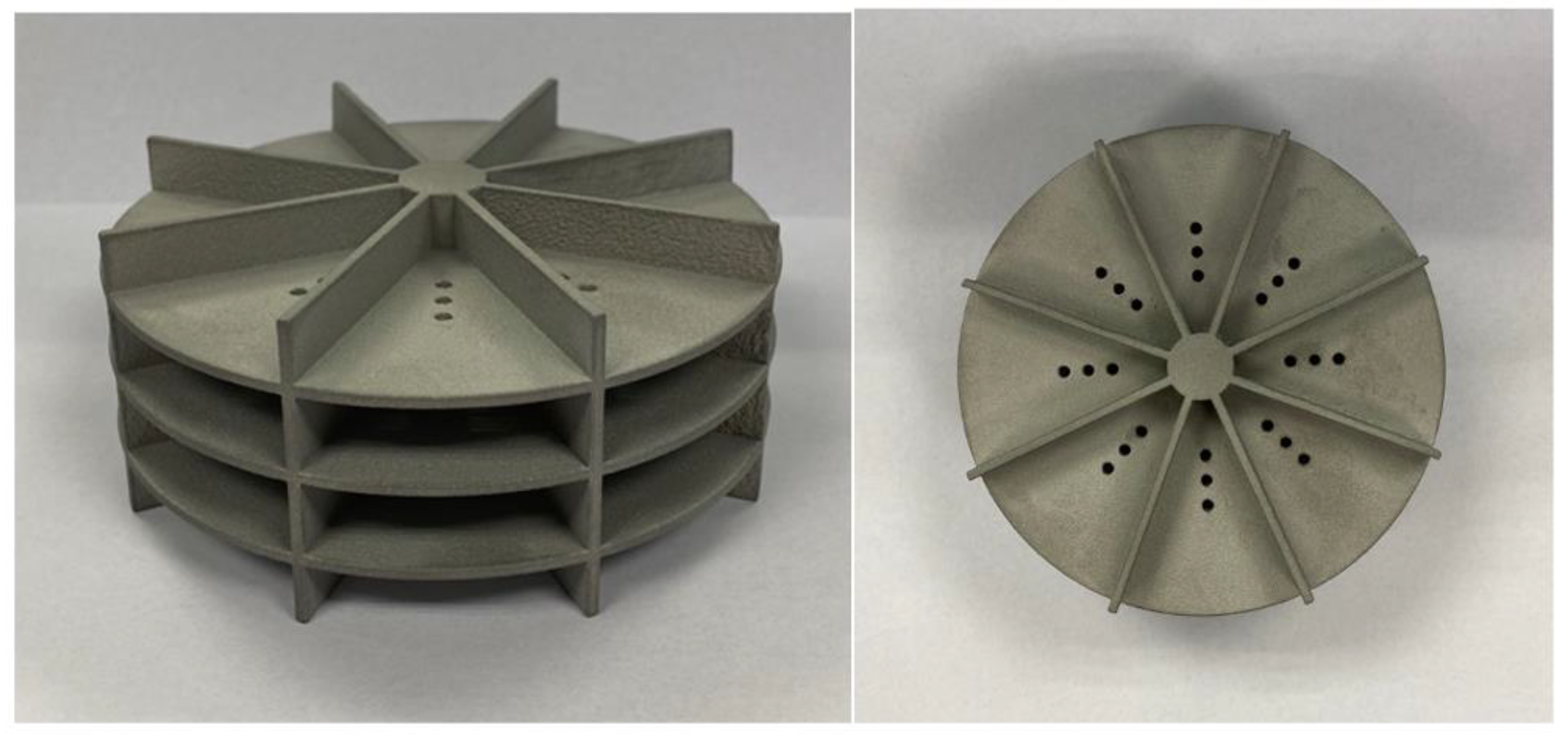
3.2. Design of a Prototype Implementing the Candidate Architecture

For the sake of simplicity and ease of manufacture, we opted for an implementation based on a circular array of sectorial apertures. Starting from a baseline model in CST Studio®—a well-established, State-of-the-Art full-wave electromagnetic simulator [51]—we utilised CST’s optimisation capabilities to obtain the final design shown in Figure 1. This model was constructed using a material with the same electrical conductivity as AlSi10Mg, which was also used in the prototype developed for the experimental proof of concept described in Section 4.
Our final design consists of a circular array with two rows of eight sector waveguide apertures, each fed through 50 Ω coaxial lines. The diameter of the circular plates is 90 mm, with a distance of 10 mm between them. To improve isolation between the feeding ports, we added 10 mm high flanges to both the upper and lower plates. All elements have a width of 1.5 mm, selected based on the manufacturing method we chose for the prototype (details are provided in Section 4). We incorporated a central 15 mm diameter metallic post for mechanical robustness, and the feeding points are positioned on the symmetry plane of the sectors, 21 mm from the centre of the circular plates. We determined this distance through an optimisation process aimed at achieving return losses below 10 dB and isolation between adjacent feeding points greater than 40 dB. Although these values are not specified in existing standards, we set them as design goals based on our experience in the field.
This configuration generates eight fixed monopulse beams, each directed at an azimuth angle of φ B , n = n π / 4   radians, where 0 n 7 , thus ensuring full 360° coverage. The elevation angle is fixed at θ B = π / 2 radians. Each monopulse pattern is formed by feeding a cluster of four sector antennas, as illustrated in Figure 2.
Figure 3a depicts the classical monopulse architecture implemented using circuit components. The circuits employed to combine the signals received from the four antennas are 180° hybrid couplers, characterised by the scattering matrix shown in Equation (2), referenced to ports 1–4 as depicted in Figure 3b. Note that labels I-IV in Figure 3b refer to the corresponding sector in Figure 2.
S = 1 2 1 1 1 1 0 0 0 0 0 0 0 0 1 1 1 1
Assuming that all ports are terminated with the circuit’s characteristic impedance Z 0 , it follows that b 1 = b 2 = 0 and a 3 = a 4 = 0 , while a 1 and a 2 represent the input signals. Consequently, the output signals at ports 3 and 4 can be expressed as:
0 0 b 3 b 4 = 1 2 1 1 1 1 0 0 0 0 0 0 0 0 1 1 1 1 a 1 a 2 0 0 ,
This leads to b 3 = a 1 + a 2 / 2 and b 4 = a 1 a 2 / 2 .
Therefore, according to the diagram in Figure 3a, the Σ (sum) channel is obtained by coherently adding the signals received from all four sectors (i.e., I + II + III + IV). The Δ φ (azimuth difference) channel is formed by adding the signals from sectors I and IV, and subtracting those from sectors II and III (i.e., I + IV − II − III). Similarly, the Δ θ (elevation difference) channel is derived by adding the signals from sectors I and II, and subtracting those from sectors III and IV (i.e., I + II − III − IV).
The azimuth and elevation off-boresight angles ( φ O B and θ O B , respectively) are then determined by comparing the phase of the corresponding Δ channel with that of the Σ channel [29]:
φ O B = 2 atan Δ φ Σ
θ O B = 2 atan Δ θ Σ
The corresponding azimuthal boresight angle ( φ B , n ) is determined by the sectors through which the signals are received, while the elevation boresight is fixed at θ B = π / 2 in all cases. The angular position of the targets is, therefore, computed as:
φ = φ B , n + 2 atan Δ φ Σ
θ = π 2 + 2 atan Δ θ Σ
Figure 4 shows the scattering parameters of the antenna presented in Figure 2, obtained using CST, with port labelling consistent with that defined in Figure 3. The results demonstrate that both the return losses and isolation are well below the design targets at the radar operating frequency (24 GHz). These results confirm that the design criteria have been satisfied, with a comfortable margin to accommodate potential manufacturing effects.
Figure 5a shows the 3D Σ radiation pattern in dBi, Figure 5b shows the horizontal 2D cut, and Figure 6 shows the simulated radiation patterns for the Σ and Δ φ channels on the horizontal plane ( θ = 90 ° ) for a boresight angle of φ B , n = 45 ° . Figure 7 and Figure 8 illustrate the corresponding Σ and Δ θ patterns on the vertical plane for the same boresight direction. Figure 5b’s 2D cut in the horizontal plane exhibits a ripple of ± 1.5 dB, which is typical for electrically large antennas, exceeding 5.5 λ in the horizontal plane for the specified boresight angle in our case. This antenna size is necessary to achieve the desired gain. Similar behaviour has been reported in the literature (see, for instance, [46]).
Accordingly, the Σ radiation pattern exhibits a gain of 13.1 dBi, with −3 dB beamwidths of φ 3 d B = 84 ° in the horizontal plane and θ 3 d B = 95 ° in the vertical plane. Regarding the different patterns, the most relevant parameter is the depth of the null, which reaches 58 dB in the Δ φ pattern and 26 dB in the Δ θ   pattern.
Figure 8 corresponds to a boresight angle of φ B = 45 ° . As expected from the antenna’s symmetry, we obtained similar patterns for the other seven boresight angles. When combined, these patterns provide a full 360° azimuthal monopulse coverage, as illustrated in Figure 9.

4. Experimental Proof of Concept

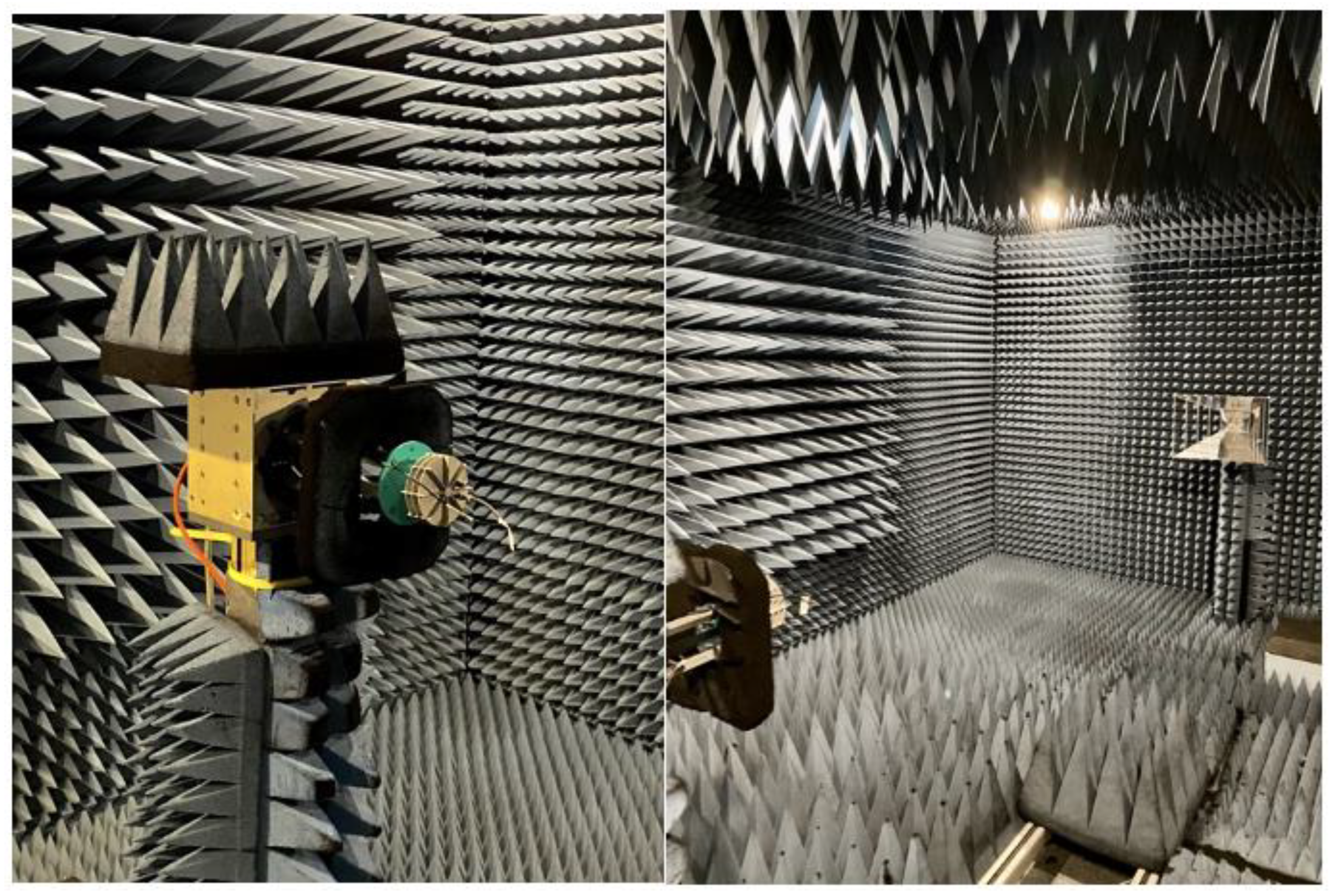
4.1. Materials and Methods
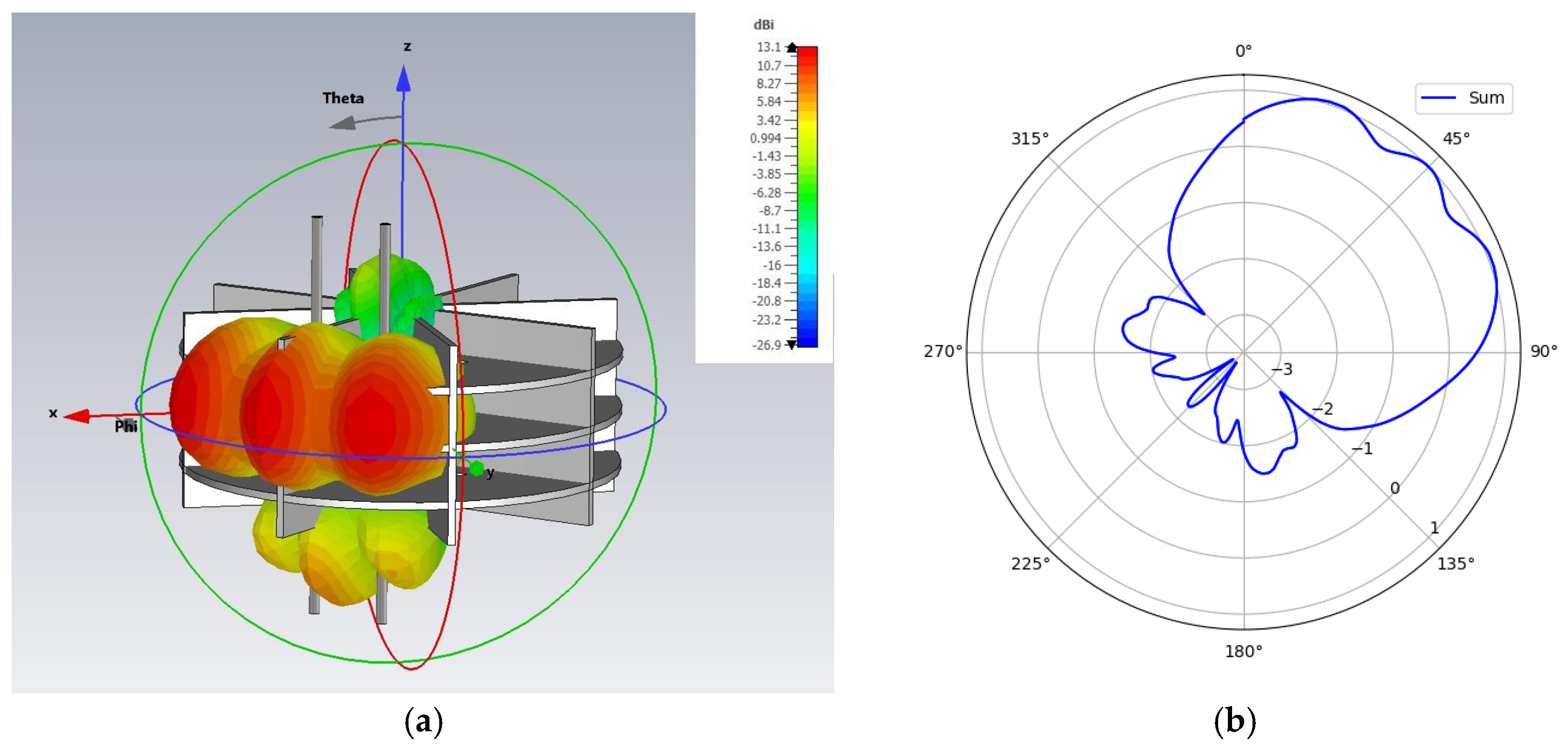
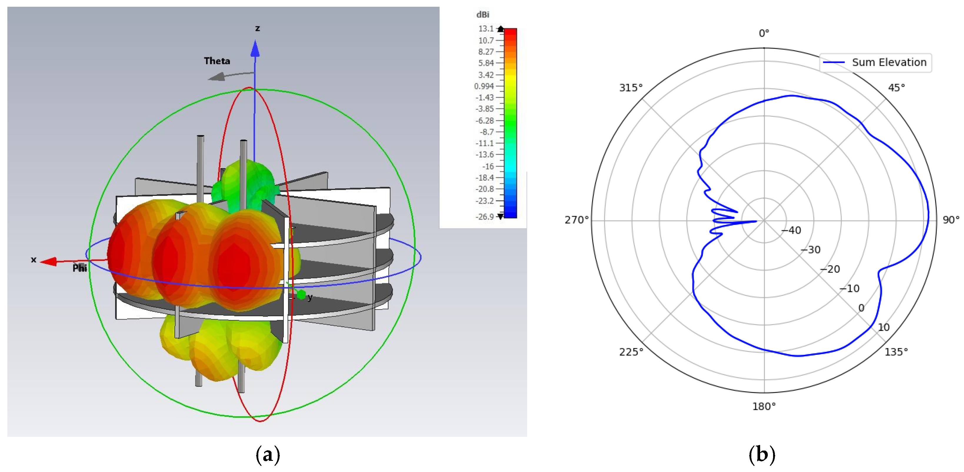
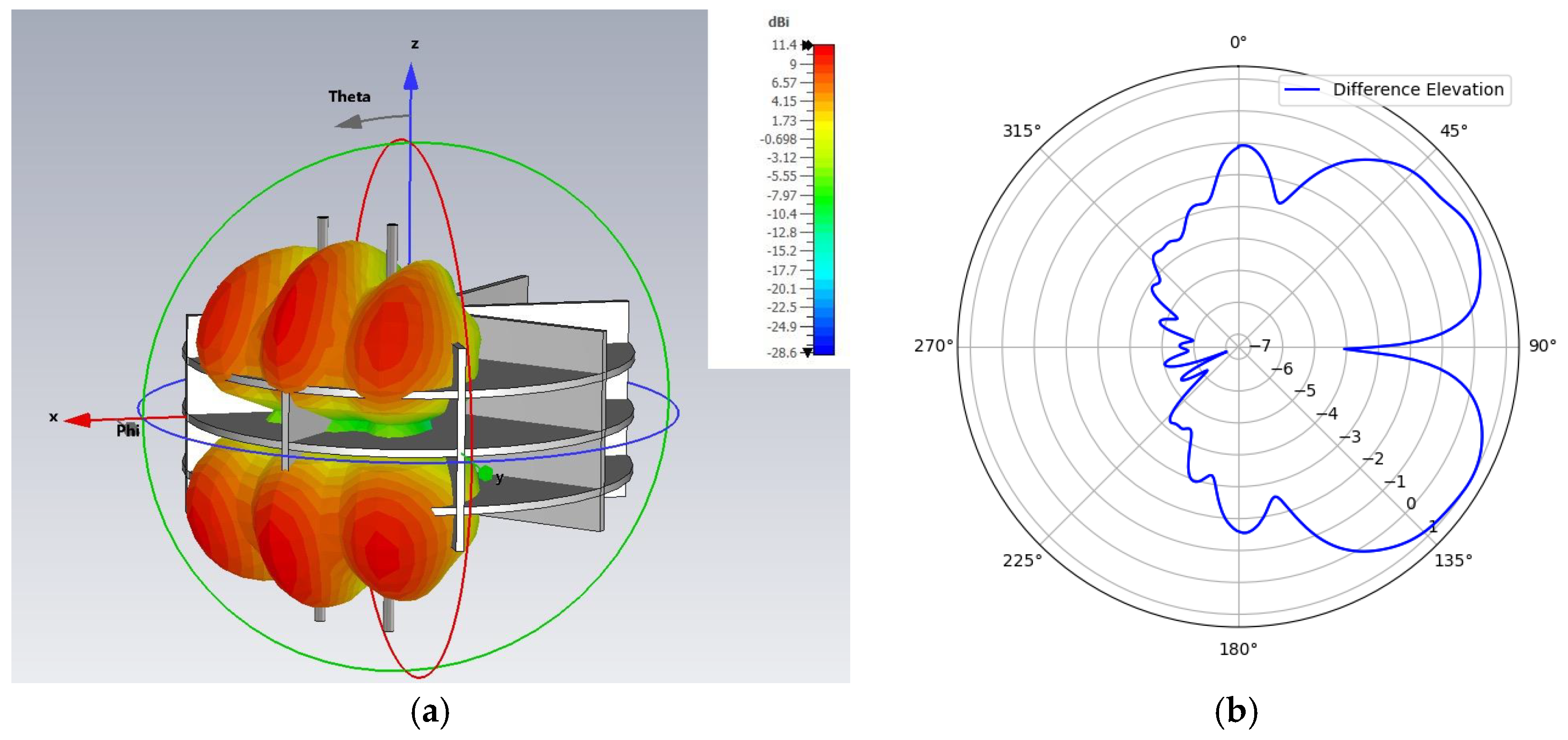
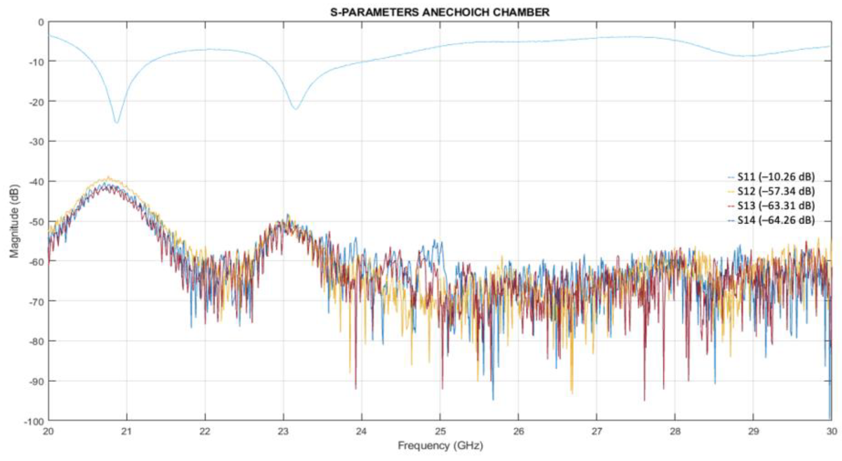
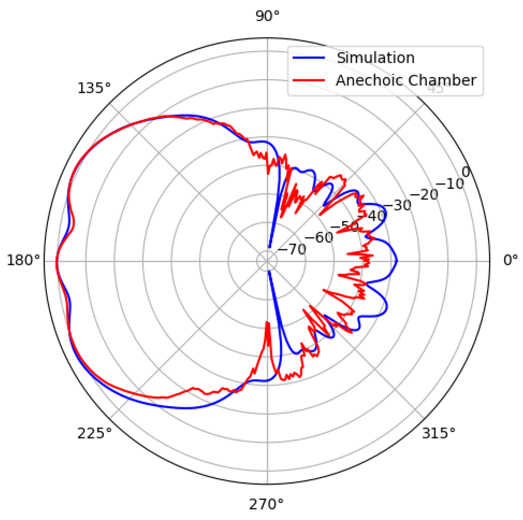
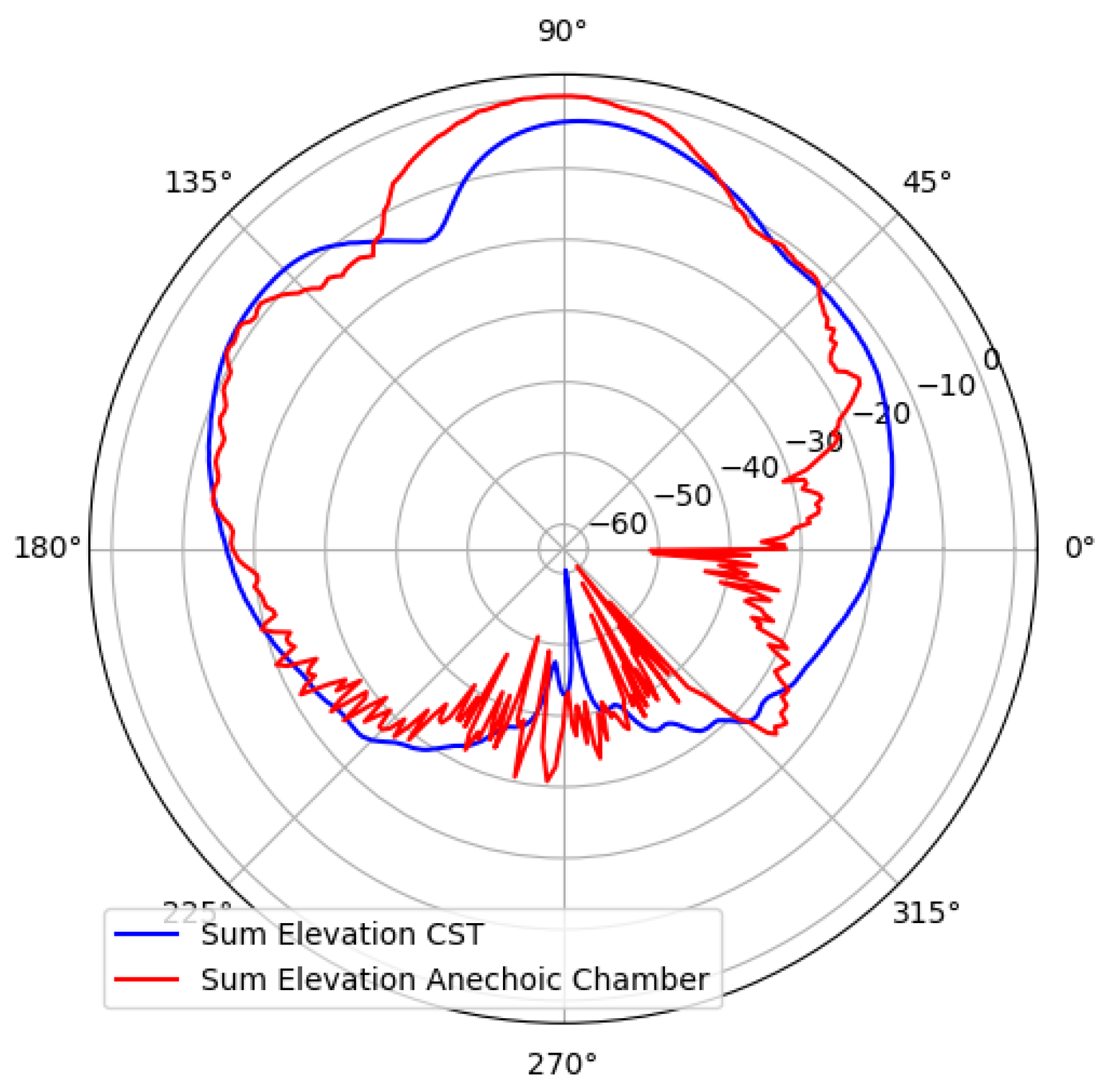
In order to experimentally prove our radar antenna concept, we used the CST model shown in Figure 1 to design a prototype, which was manufactured by PCBWay in Shenzhen, China [52] in aluminium (AlSi10Mg) using Selective Laser Melting (SLM) technology. The resulting prototype, shown in Figure 10, weighs 163 g.
We measured the prototype shown in Figure 10 in the anechoic chamber at the Antennas and Propagation Laboratory (APL) on the Universitat Politècnica de València (UPV) campus. The chamber’s measurement space is 3 m long, 2 m wide, and 2 m high, and it is equipped with a spherical measurement system capable of characterising antenna scattering parameters and radiation patterns up to 50 GHz.
In light of the antenna’s symmetry, we measured the radiation pattern for a single boresight angle. Using the experimental setup shown in Figure 11, we measured the scattering parameters between the ports defined in Figure 2, along with the horizontal and vertical cuts of the radiation pattern and the antenna gain. These results are presented in Section 4.2 below.

4.2. Results

We present the scattering parameters that we measured in the lab in Figure 12. Although the return losses (S11) are higher than the figure that we obtained by simulation (15.33 dB), that value still fulfils the design requirement specified in Section 2 (10 dB). The isolation between ports in Figure 12 is also poorer than in the simulated results, but still acceptable considering the requirements (40 dB minimum).
Figure 13 and Figure 14 illustrate the comparison between the measured (red) and simulated (blue) Σ and Δ φ radiation patterns on the horizontal plane, while the corresponding results for the Σ and Δ θ patterns on the vertical plane are shown in Figure 15 and Figure 16.
Figure 13, Figure 14, Figure 15 and Figure 16 show a notable agreement between the measured and simulated patterns, with small differences in the side and back lobes attributed to the mast used to fix the prototype during the measurements. Additionally, the slight discrepancy in the depth of the null in the Δ φ pattern is due to the sensitivity of the measurement process. Lastly, we measured a gain of 11.8 dBi, with the difference from the design target (13 dBi) easily compensable through radar processing techniques not accounted for in Equation (1), such as signal integration.

5. Discussion and Conclusions

In this paper, we have introduced and validated a monopulse antenna concept designed for Collision Avoidance (CA) systems aimed at preventing collisions between Unmanned Aircraft (UA) with a maximum dimension of less than 25 feet (typically used in UAS operations within the specific category, as defined by the European Regulation), with the Remain Well Clear (REC) function managed by ground-based U-space/UTM services. This antenna enables the detection of large intruders (GA and UAM/AAM aircraft) at approximately 2000 feet from the ownship, and small UAs (sUA) at around 200 feet (which are the RWC limits defined by State-of-the-Art applicable standards), using CW-LFM radars implemented with COTS components at 24 GHz. We employed a well-established full-wave electromagnetic simulator (CST) to design a prototype, which was fabricated using Selective Laser Melting (SLM) 3D printing technology with AlSi10Mg. The prototype features a low aerodynamic profile that does not compromise the ownship’s airworthiness, weighs 163 g, and costs approximately 200 euros. We measured the antenna’s performance in an anechoic chamber, where the results closely matched the simulated design and met the specified requirements. The findings presented in this paper demonstrate that the proposed concept currently holds a Technology Readiness Level (TRL) of 3, according to the scale used in European R&D framework programs [53] (i.e., experimental proof of concept). This makes it a strong candidate for radar antenna development for CA systems intended for small, unmanned UAS. However, further research is needed to evaluate the effect of the radome and potential interferences with other airborne systems, as well as to explore alternative technologies such as groove waveguides, which could lead to lighter antennas with even lower aerodynamic load.

Author Contributions

Conceptualization, J.V.B.; methodology, M.F.-B. and J.R.A.; validation, J.R.A.; formal analysis, M.F.-B.; resources, J.V.B.; writing—original draft preparation, J.R.A.; writing—review and editing, J.V.B. and M.F.-B.; supervision, M.F.-B. and J.V.B. All authors have read and agreed to the published version of the manuscript.

Funding

This research was conducted within the framework of the CREATE U-space project. The CREATE U-space project (CIAICO/2022/044) has received funding from the Conselleria de Innovación, Universidades, Ciencia y Sociedad Digital of the Generalitat Valenciana.

Institutional Review Board Statement

Not applicable.

Informed Consent Statement

Not applicable.

Data Availability Statement

The original contributions presented in this study are included in the article. Further inquiries can be directed to the corresponding authors.

Acknowledgments

We kindly appreciate the support of Bernardo Bernardo from UPV’s APL in conducting the experimental characterisation of the prototype.

Conflicts of Interest

The authors declare no conflicts of interest.

Abbreviations

The following abbreviations are used in this manuscript:
AAMAdvanced Air Mobility
ACASAirborne Collision Avoidance System
AoAAngle of Arrival
APLAntennas and Propagation Lab
ARCAir Risk Class
ATARAir-to-Air RADAR
CACollision Avoidance
ConOpsConcept of Operation
COTSCommercial-Off-The-Shelf
CW-LFMContinuous Wave, Linearly Frequency Modulated,
DAADetect and Avoid
EEAEuropean Economic Area
EUEuropean Union
EUROCAEEuropean Organisation for Civil Aviation Equipment
FFTFast Fourier Transform
FOVField of Vision
GAGeneral Aviation
GRCGround Risk Class
ICAOInternational Civil Aviation Organisation
IFRInstrumental Flight Rules
ISMIndustrial, Medical, and Scientific
MACMid-Air Collision
MOPSMinimum Operational Performance Standard
NMACNear Mid-Air Collision
OSEDOperational Services and Environment Description
RPASRemotely Piloted Aircraft Systems
RTCARadiotechnical Commission for Aeronautics
RWCRemain Well Clear
SCSpecial Committee
SESARSingle European Sky Air Traffic Management Research
SLMSelective Laser Melting
sNMACsmall UAS NMAC
SORASpecific Operations Risk Assessment
sUASmall UA
SWaPSize, Weight, and Power
TCRTactical Conflict Resolution
TRLTechnology Readiness Level
VFRVisual Flight Rules
VLLVery Low Level
UAUnmanned Aircraft
UAMUrban Air Mobility
UASUnmanned Aircraft System
UTMUnmanned Aircraft System Traffic Management

References

  1. International Civil Aviation Organisation. Cir 328, Umanned Aircraft Systems (UAS); International Civil Aviation Organisation: Montréal, QC, Canada, 2011. [Google Scholar]
  2. Imperial War Museums. Available online: https://www.iwm.org.uk/history/a-brief-history-of-drones (accessed on 17 March 2025).
  3. Wagner, W. Lightning Bugs, and other Reconnaissance Drones; Aero Publishers, Inc.: Fallbrook, CA, USA, 1982. [Google Scholar]
  4. European Drones Outlook Study; SESAR JU: Brussels, Belgium, 2016; Available online: https://www.sesarju.eu/sites/default/files/documents/reports/European_Drones_Outlook_Study_2016.pdf (accessed on 17 March 2025).
  5. ED-267 Operational Services & Environment Description (OSED) for Detect & Avoid in Very Low-Level Operations; European Organisation for Civil Aviation Equipment (EUROCAE): Saint-Denis, France, 2020.
  6. European Union Aviation Safety Agency. Study on the Societal Acceptance of Urban Air Mobility in Europe; European Union Aviation Safety Agency (EASA): Cologne, Germany, 2021. [Google Scholar]
  7. Commission Implementing Regulation (EU) 2019/947 of 24 May 2019 on the Rules and Procedures for the Operation of Unmanned Aircraft. Available online: https://eur-lex.europa.eu/eli/reg_impl/2019/947/oj/eng (accessed on 15 March 2025).
  8. European Union Aviation Safety Agency. Easy Access Rules for Unmanned Aircraft Systems; European Union Aviation Safety Agency (EASA): Cologne, Germany, 2024. [Google Scholar]
  9. European Union Aviation Safety Agency. EASA Concept for Regulation of Unmanned Aircraft Systems (UAS) Operations in the ‘Certified’ Category and Urban Air Mobility—Issue 3.0; European Union Aviation Safety Agency (EASA): Cologne, Germany, 2021. [Google Scholar]
  10. Federal Aviation Administration. Concept of Use for the Airborne Collision Avoidance System Xu for Smaller UAS (ACAS sXu); Version 2; Federal Aviation Administration (FAA): Washington, DC, USA, 2020. [Google Scholar]
  11. International Civil Aviation Organisation. Global Air Traffic Management Operational Concept, 1st ed.; International Civil Aviation Organisation (ICAO): Montréal, QC, Canada, 2005. [Google Scholar]
  12. Radiotechnical Commission for Aeronautics. DO-396 Minimum Operational Performance Standards for Airborne Collision Avoidance System sXu (ACAS sXu); Radiotechnical Commission for Aeronautics (RTCA): Washington, DC, USA, 2023. [Google Scholar]
  13. Commission Implementing Regulation (EU) 2021/666 of 22 April 2021 amending Regulation (EU) No 923/2012 as regards requirements for manned aviation operating in U-space airspace. Available online: https://eur-lex.europa.eu/eli/reg_impl/2021/666/oj/eng (accessed on 15 March 2025).
  14. RTCA Paper No. 261-22/PMC-2336. Radiotechnical Commission for Aeronautics (RTCA). Available online: https://www.rtca.org/wp-content/uploads/2024/07/SC-147-TOR-Rev-20-Approved-2022-09-15-1.pdf (accessed on 17 March 2025).
  15. International Civil Aviation Organisation. Unmanned Aircraft Systems Traffic Management (UTM)—A Common Framework with Core Principles for Global Harmonization, 4th ed.; International Civil Aviation Organisation: Monteral, QC, Canada, 2023. [Google Scholar]
  16. UTM Concept of Operations, v2.0, Federal Aviation Administration, v2.0, 2020. Available online: https://www.faa.gov/researchdevelopment/trafficmanagement/utm-concept-operations-version-20-utm-conops-v20 (accessed on 17 March 2025).
  17. NavCanada. RPAS Traffic Management (RTM) System: Concept of Operations, Version 1.1; NavCanada: Ottawa, ON, USA, 2023; Available online: https://www.navcanada.ca/en/rpas-conops.pdf (accessed on 15 March 2025).
  18. U-space ConOps and architecture, Ed. 4.0, CORUS-XUAM project, 2023. Available online: https://www.sesarju.eu/node/4544 (accessed on 17 March 2025).
  19. SESAR Joint Undertaking. European ATM Master Plan, 2020th ed.; SESAR Joint Undertaking: Brussels, Belgium, 2020; Available online: https://www.sesarju.eu/sites/default/files/documents/reports/SESAR%20Master%20Plan%202025.pdf (accessed on 15 March 2025).
  20. Commission Delegated Regulation (EU) 2019/945 of 12 March 2019 on Unmanned Aircraft Systems and on Third-Country Operators of Unmanned Aircraft Systems. Available online: https://eur-lex.europa.eu/eli/reg_del/2019/945/oj/eng (accessed on 15 March 2025).
  21. Commission Delegated Regulation (EU) 2020/1058 of 27 April 2020 Amending Delegated Regulation (EU) 2019/945 as Regards the Introduction of Two New Unmanned Aircraft Systems Classes. Available online: https://eur-lex.europa.eu/eli/reg_del/2020/1058/oj/eng (accessed on 15th March 2025).
  22. Commission Implementing Regulation (EU) 2021/664 of 22 April 2021 on a Regulatory Framework for the U-Space. Available online: https://eur-lex.europa.eu/eli/reg_impl/2021/664/oj/eng (accessed on 15 March 2025).
  23. Commission Implementing Regulation (EU) 2021/665 of 22 April 2021amending Implementing Regulation (EU) 2017/373 as Regards Requirements for Providers of Air Traffic Management/Air Navigation Services and Other Air Traffic Management Network Functions in the U-Space Airspace Designated in Controlled Airspace. Available online: https://eur-lex.europa.eu/eli/reg_impl/2021/665/oj/eng (accessed on 15 March 2025).
  24. European Union Aviation Safety Agency. Easy Access Rules for U-Space; European Union Aviation Safety Agency (EASA): Cologne, Germany, 2024. [Google Scholar]
  25. SESAR Joint Undertaking. European ATM Master Plan, 2025th ed.; SESAR Joint Undertaking: Brussels, Belgium, 2025. [Google Scholar]
  26. SPATIO. Available online: https://research.dblue.it/spatio/ (accessed on 17 March 2025).
  27. Radiotechnical Commission for Aeronautics. DO-366 Minimum Operational Performance Standards for Air-to-Air Radar for Traffic Surveillance; Radiotechnical Commission for Aeronautics (RTCA): Washington, DC, USA, 2020. [Google Scholar]
  28. European Organisation for Civil Aviation Equipment. EUROCAE ED-275—Minimum Operational Performance Standard (MOPS) for ACAS Xu; European Organisation for Civil Aviation Equipment (EUROCAE): Saint-Denis, France, 2019. [Google Scholar]
  29. International Civil Aviation Organisation. Aeronautical Surveillance Manual (Doc. 9924), 3rd ed.; International Civil Aviation Organisation (ICAO): Montréal, QC, Canada, 2020. [Google Scholar]
  30. F3442/F3442M-20; Standard Specification for Detect and Avoid System Performance Requirement, The American Society for Test and Materials (ASTM). New York Office: New York, NY, USA, 2020.
  31. International Telecommunication Union, Article 5 of the ITU Radio Regulations (edition 2012): Geneva, Switzerland. Available online: https://www.itu.int/pub/R-REG-RR (accessed on 15 March 2025).
  32. IEEE 802.15.1-2005; IEEE Standard for Information Technology—Local and Metropolitan Area Networks—Specific Requirements—Part 15.1a: Wireless Medium Access Control (MAC) and Physical Layer (PHY) Specifications for Wireless Personal Area Networks (WPAN). IEEE: Piscataway, NJ, USA, 2005.
  33. IEEE 802.11b-1999; IEEE Standard for Information Technology—Telecommunications and Information Exchange Between Systems—Local and Metropolitan Networks—Specific Requirements—Part 11: Wireless LAN Medium Access Control (MAC) and Physical Layer (PHY) Specifications: Higher Speed Physical Layer (PHY) Extension in the 2.4 GHz Band. IEEE: Piscataway, NJ, USA, 1999.
  34. Wide Band Solid State Power Amplifier 18 GHz–26.5 GHz. Available online: https://www.rflambda.com/pdf/poweramplifier/RFLUPA18G26GF.pdf (accessed on 17 March 2025).
  35. ADF5904. 4-Channel, 24 GHz, Receiver Downconverter. Available online: https://www.analog.com/en/products/adf5904.html (accessed on 17 March 2025).
  36. Skolnik, M.I. Introduction to Radar Systems, 3rd ed.; McGraw-Hill Education: New York, NY, USA, 2000. [Google Scholar]
  37. Semkin, V.; Haarla, J.; Pairon, T.; Slezak, C.; Viikari, V. Analyzing Radar Cross Section Signatures of Diverse Drone Models at mmWave Frequencies. IEE Access 2020, 8, 48958–48969. [Google Scholar] [CrossRef]
  38. Mahafza, B.R. Radar Systems Analysis and Desing Using Matlab; Chapman and Hall: London, UK, 2020. [Google Scholar]
  39. Skolnik, M.I. (Ed.) Radar Handbook, 3rd ed.; McGraw-Hill Education: New York, NY, USA, 2008. [Google Scholar]
  40. Meikle, H. Modern Radars, 2nd ed.; Artech House: Washington, DC, USA, 2008. [Google Scholar]
  41. Skolnic, M. Systems Aspects of Digital Beamforming Ubiquitous Radars; Naval Research Laboratory: Washington, DC, USA, 2002. [Google Scholar]
  42. de Quevedo, Á.D.; Urzaiz, F.I.; Menoyo, J.G.; López, A.A. Drone Detection With X-Band Ubiquitous Radar. In Proceedings of the 2018 19th International Radar Symposium (IRS), Bonn, Germany, 20–22 June 2018; pp. 1–10. [Google Scholar] [CrossRef]
  43. Moses, A.; Rutherford, M.J.; Valavanis, K.P. Radar-based detection and identification for miniature air vehicles. In Proceedings of the 2011 IEEE International Conference on Control Applications (CCA), Denver, CO, USA, 28–30 September 2011; pp. 933–940. [Google Scholar] [CrossRef]
  44. Hägelen, M.; Jetten, R.; Kulke, R.; Ben, C.; Krüger, M. Monopulse Radar for Obstacle Detection and Autonomous Flight for Sea Rescue UAVs. In Proceedings of the 2018 19th International Radar Symposium (IRS), Bonn, Germany, 20–22 June 2018; pp. 1–7. [Google Scholar] [CrossRef]
  45. Milias, C.; Andersen, R.B.; Lazaridis, P.I.; Zaharis, Z.D.; Muhammad, B.; Kristensen, J.T.B. End-fire antenna array with metamaterial decoupling structures for UAV-borne radar. In Proceedings of the 2022 3rd URSI Atlantic and Asia Pacific Radio Science Meeting (AT-AP-RASC), Gran Canaria, Spain, 29 May–3 June 2022; pp. 1–4. [Google Scholar] [CrossRef]
  46. Al, H.; Johnson, D. A Modular Conformal Antenna Array for Wide-Beam SAR and DAA Radars. In Proceedings of the 2023 IEE International Radar Conference, Sydney, Australia, 6–10 November 2023. [Google Scholar] [CrossRef]
  47. Li, B.; Fei, Z.; Zhang, Y. UAV Communications for 5G and Beyond: Recent Advances and Future Trends. IEEE Internet Things J. 2019, 6, 2241–2263. [Google Scholar] [CrossRef]
  48. Wilson, N.; Kumar, A.; Jha, A.; Cenkeramaddi, L.R. Multitarget Angle of Arrival Estimation Using Rotating mmWave FMCW Radar and Yolov3. IEEE Sens. J. 2023, 23, 3173–3182. [Google Scholar] [CrossRef]
  49. Cenkeramaddi, L.R.; Rai, P.K.; Dayal, A.; Bhatia, J.; Soumya, J. A Novel Angle Estimation for mmWave FMCW Radars Using Machine Learning. IEEE Sens. J. 2021, 21, 9833–9843. [Google Scholar] [CrossRef]
  50. Wang, Z.; Sinha, A.; Willett, P.; Bar-Shalom, Y. Angle estimation for two unresolved targets with monopulse radar. IEEE Trans. Aerosp. Electron. Syst. 2004, 40, 998–1019. [Google Scholar] [CrossRef]
  51. CST Studio Suite. Available online: https://www.3ds.com/es/products/simulia/cst-studio-suite (accessed on 17 March 2025).
  52. PCBWay. PCB Prototype the Easy Way. Available online: https://www.pcbway.com (accessed on 17 March 2025).
  53. G. Technology Readiness Levels (TRL). Available online: https://ec.europa.eu/research/participants/data/ref/h2020/other/wp/2018-2020/annexes/h2020-wp1820-annex-g-trl_en.pdf (accessed on 18 March 2025).
Figure 1. Final model of the radar antenna in CST.
Applsci 15 05618 g001
Figure 2. Representative view of the excited cavities.
Applsci 15 05618 g002
Figure 3. (a) Block diagram of a 3D monopulse receiver; (b) labelling of ports of the 180 ° hybrid couplers used to illustrate the concept of a monopulse receiver.
Applsci 15 05618 g003
Figure 4. S parameters of the antenna prototype obtained by simulation using CST.
Applsci 15 05618 g004
Figure 5. (a) 3D Σ radiation pattern in dBi; (b) 2D cut in the horizontal plane Σ φ , θ = 90 ° .
Applsci 15 05618 g005
Figure 6. (a) 3D Δ φ radiation pattern in dBi; (b) 2D cut in the horizontal plane Δ φ   φ , θ = 90 ° .
Applsci 15 05618 g006
Figure 7. (a) 3D Σ radiation pattern in dBi; (b) 2D cut in a vertical plane Σ φ = 45 ° , θ .
Applsci 15 05618 g007
Figure 8. (a) 3D Δ θ radiation pattern in dBi; (b) 2D cut in a vertical plane Δ θ φ = 45 ° , θ .
Applsci 15 05618 g008
Figure 9. Overlapped monopulse azimuthal coverage.
Applsci 15 05618 g009
Figure 10. Antenna prototype.
Applsci 15 05618 g010
Figure 11. Measurement setup in the anechoic chamber.
Applsci 15 05618 g011
Figure 12. Antenna S-parameters measured in the Anechoic Chamber.
Applsci 15 05618 g012
Figure 13. Comparison of the simulated and measured Σ diagrams on the horizontal plane.
Applsci 15 05618 g013
Figure 14. Comparison of the simulated and measured Δ φ diagrams on the horizontal plane.
Applsci 15 05618 g014
Figure 15. Comparison of the simulated and measured Σ patterns on the vertical plane.
Applsci 15 05618 g015
Figure 16. Comparison of the simulated and measured Δ θ patterns on the vertical plane.
Applsci 15 05618 g016
Disclaimer/Publisher’s Note: The statements, opinions and data contained in all publications are solely those of the individual author(s) and contributor(s) and not of MDPI and/or the editor(s). MDPI and/or the editor(s) disclaim responsibility for any injury to people or property resulting from any ideas, methods, instructions or products referred to in the content.

