Article

Advancing Discontinuous-Model Predictive Control for High Performance Inverters via Optimized Zero-Voltage State Selection Based on Offset Voltage

Division of Marine System Engineering, Korea Maritime and Ocean University, 727 Taejong-ro, Yeongdo-gu, Busan 49112, Republic of Korea
*
Author to whom correspondence should be addressed.
Appl. Sci. 2025, 15(10), 5532; https://doi.org/10.3390/app15105532
Submission received: 15 April 2025 / Revised: 12 May 2025 / Accepted: 12 May 2025 / Published: 15 May 2025
(This article belongs to the Special Issue Power Electronics: Control and Applications)

Abstract

:
Electric propulsion ships have garnered significant attention for addressing the environmental impact associated with conventional shipping vessels. Their performance critically depends on the inverters that control propulsion motors. This study aims to enhance inverter control by addressing the limitations of conventional model predictive control (MPC), particularly its high current errors and total harmonic distortion (THD) owing to the limited switching frequency. Herein, a discontinuous MPC is proposed that is capable of reducing the switching losses by implementing discontinuous switching during high current periods. This approach employs zero-voltage vectors that are selected based on the polarity of the offset voltage to prevent unnecessary switching losses. Experimental results indicate that the proposed approach reduces the current error by up to 45%, THD by up to 30%, and switching losses by 15–25%. Therefore, this study demonstrates the potential of the proposed control strategy to improve the efficiency and reliability of electric propulsion systems, thereby contributing to the advancement of inverter control technology and development of eco-friendly shipping vessels.

1. Introduction

The continuous rise in greenhouse gas emissions has exacerbated global warming and climate change, which are crucial environmental challenges that require immediate international action [1]. Consequently, various countries have established carbon neutrality (Net-Zero) targets and implemented strong policies aimed at reducing greenhouse gas emissions. In particular, the transportation sector faces significant pressure owing to high carbon emissions [2]. According to the International Energy Agency (IEA), the transportation sector accounts for 16% of the total greenhouse gas emissions, with maritime shipping accounting for approximately 3% [3,4]. Reports indicate that a single large vessel can emit hundreds of thousands of tons of greenhouse gases annually, highlighting the necessity for developing emission reduction technologies within shipping industries [5,6,7,8,9,10].
To address this, the International Maritime Organization (IMO) has set a target to reduce carbon emissions in international shipping by 100% by 2050 relative to emission levels in 2008. To achieve this objective, progressively stringent environmental regulations are being implemented. These enhanced regulations have significantly increased the difficulty of operating conventional internal combustion engine vessels, making it essential to develop technological alternatives. Among these, electric propulsion ships have gained considerable attention as a leading ecofriendly option. Unlike vessels based on conventional internal combustion engines, electric propulsion ships employ electrical energy, thereby eliminating emissions associated with fossil fuel combustion. They also present advantages such as improved energy efficiency and precise propulsion control [11,12,13].
Furthermore, electric propulsion ships are effective in reducing exhaust gases, thereby emerging as a realistic alternative to meet IMO regulations. The high-power conversion efficiency of the propulsion motors can reduce operating costs. Additionally, motor-driven propulsion systems generate less noise and vibration than internal combustion engines. This enhances the comfort of both the passengers and crew members. Consequently, major shipyards and shipping companies worldwide are actively pursuing the commercialization of electric propulsion ships. Government support for the research and development of these sectors has also been expanding. The advancement of electric propulsion ship technology is projected to become a significant factor in transforming the shipping industry in conjunction with the strengthening of environmental regulations [14,15].
The performance of electric propulsion ships is primarily determined by the efficient control of propulsion motors, which relies on optimized inverters. An inverter functions as a power conversion device that transforms the power generated from generators or batteries into a variable frequency alternating current that is suitable for motors. The power conversion efficiency increases with the improvement in the inverter performance, thereby enhancing the overall energy efficiency and stability of electric propulsion ships.
The control method is a major factor in determining the inverter performance. Different inverter control methods present variations in the output voltage quality, power conversion loss, and motor torque response characteristics. Optimizing these aspects is a major challenge.
Several inverter control methods have been analyzed, including pulse width modulation (PWM) [16,17,18], proportional-integral (PI) control [19,20,21], sliding mode control (SMC) [22,23,24], fuzzy logic control (FLC) [25,26,27], and MPC [28,29,30]. PWM involves controlling the voltage by adjusting the switching cycles. This method is widely used and is relatively simple to implement; however, it suffers from increased switching losses. PI controllers feature simple structures and easy implementation. However, they require control gain reconfiguration when the operating conditions vary and exhibit reduced performance in nonlinear systems. Furthermore, they cannot ensure optimal control performance in systems that require a high dynamic response owing to their slow transient response speeds. SMC achieves robust control performance, but it presents considerable implementation complexity. It also faces a high risk of chattering owing to discontinuities in the control inputs. In applications that require high switching frequencies, SMC may increase the switching noise and losses. The FLC demonstrates excellent adaptability in nonlinear systems. However, designing fuzzy rules is challenging, and it involves considerable trial and error. The computational demands increase with the increase in the number of control rules, thereby potentially complicating real-time control. Additionally, the fuzzy rules may require reconfiguration when the system dynamic characteristics vary. Conversely, MPC can overcome the limitations of conventional control methods by determining the optimal control inputs by predicting the future system states. It maintains a high-control performance under various operating conditions. Recently, MPC has gained considerable attention as an inverter control method. However, conventional MPC approaches face various challenges. Firstly, a low switching frequency can increase the current error and total harmonic distortion (THD) [31,32]. Secondly, increasing the switching frequency to improve the current error and THD can cause higher switching losses [28,33,34]. To address these issues, ref. [35] introduced a virtual voltage vector technique to reduce the THD. However, this approach increased the switching loss. Therefore, a new inverter control technique must be developed to maintain the current quality while reducing switching losses.
In this study, we proposed an MPC approach that incorporates discontinuous switching and zero-voltage vector selection to overcome the switching loss problems. Based on the comparison of the current and voltage magnitudes, we reduced the switching losses via discontinuous switching in the regions where the current values were maximum. Additionally, we suppressed unnecessary switching by selecting the optimal zero-voltage vectors based on the polarity of the calculated offset voltage for discontinuous switching. The proposed method employed multi-vector approaches with virtual voltage vectors to improve the current quality. Simultaneously, we applied discontinuous switching to effectively decrease the switching losses. This dual approach enhanced the inverter output performance and efficiency by improving the current distortion and reducing switching losses. The proposed method was verified via simulations and experimental tests.
These improvements help in optimizing the inverter performance and increasing the power conversion efficiency, thereby increasing the reliability of the entire electric propulsion system. The proposed Discontinuous MPC method presents more flexible operational characteristics than conventional inverter control methods and consistently maintains a stable performance across various load conditions.
This helps in advancing eco-friendly ship technology and presents considerable potential for applications across several industrial sectors where power conversion plays a crucial role. The broad applicability of the proposed approach extends beyond maritime applications to other fields that require efficient power conversion systems.
The remainder of this paper is organized as follows. Section 2 analyzes the limitations of conventional inverter control methods and MPC, focusing on current quality degradation and increased switching losses. Section 3 proposes an MPC that applies discontinuous switching, detailing the principles underlying the improvement of current distortion while reducing losses. Section 4 verifies the performance of the proposed technique via simulations and experiments, analyzing the improved current quality and reduced switching losses when compared with conventional MPCs. Finally, Section 5 summarizes the research results and presents the future research implications.

2. Conventional Finite Control Set-Model Predictive Control for Two-Level Voltage Source Inverter

2.1. Three-Phase Two-Level Inverter

Figure 1 depicts the simplest configuration of a three-phase two-level voltage source inverter. The inverter comprises one leg per phase, with each leg containing two switches, presenting a total of six switches. Each switch has two possible states, ON and OFF. The switches within the same phase (e.g., Sa and Sa′) operate complementarily, i.e., when one switch is ON, its corresponding switch must be OFF. This complementary operation prevents short circuits during the switching transitions. When the ON state is represented as ‘1’, and the OFF state is represented as ‘0’, the switching state for each leg is defined as follows:
S a + S a = 1 S b + S b = 1 S c + S c = 1
Owing to these switching characteristics, each phase can output two voltage levels (+Vdc/2 or −Vdc/2). The three-phase AC output voltage of the inverter is determined by a combination of the switching states across all the phase legs. The output voltage generation process can be explained using the space-vector pulse width modulation (SVPWM) of the three-phase inverters. The SVPWM represents the three-phase output voltage as a single-space vector in a complex plane. The inverter selects the specific voltage vectors that exist within this space vector. This approach enables the inverter to generate three-phase AC outputs with various frequencies and magnitudes.
A two-level voltage source inverter has eight possible switching states, corresponding to eight output voltage vectors. The output voltage vectors generated by each switching-state combination are as follows:
V a b c = v a n v b n v c n = V d c ( S a 1 2 ) ( S b 1 2 ) ( S c 1 2 )
where V a b c denotes the output voltage vector; v a n , v b n , and v c n denote the output voltages of each phase; V d c denotes the DC link voltage; and S a , S b , and S c denote the switching states of each phase.
The eight output voltage vectors comprise six active voltage vectors and two zero-voltage vectors. All the active voltage vectors exhibit an identical magnitude of 2Vdc/3 but vary in phase. Since the two zero-voltage vectors exhibit different switching states but have identical values, the inverter effectively comprises seven distinct voltage vectors. The proper utilization of these zero-voltage vectors significantly affects the inverter efficiency and output quality [36,37,38].
Figure 2 depicts the space voltage vectors corresponding to the switching states of the two-level inverter.
The output voltage vector, V a b c , can be expressed in the α-β coordinate system through Clarke transformation as follows:
V α V β = 2 3 1 1 2 1 2 0 3 2 3 2 v a n v b n v c n
These voltage vectors are used in the MPC to predict future output voltages and determine the optimal switching states.

2.2. Load Model

Three-phase loads connected to the inverters are typically modeled as circuits comprising resistance, inductance, and back-EMF. The relationship between the inverter output and load in this three-phase model can be expressed as follows:
L o d d t i a o i b o i c o + R o i a o i b o i c o + e a e b e c = v a n v b n v c n
where i a o , i b o , and i c o denote the three-phase load current vector; v a n , v b n , and v c n denote the inverter output voltage vector; e a , e b , and e c denote the load back-EMF; and R o and L o denote the load resistance and inductance, respectively.
This equation can be transformed into the stationary α-β coordinate system through Clarke transformation as follows:
L o d d t i α i β + R o i α i β + e α e β = V α V β
where i α and i β , V α and V β , and e α and e β denote the currents, voltages, and back-EMF in the α-β coordinate system, respectively.
Equations (4) and (5) express the continuous-time state-space equations; however, discretization is necessary in actual digital control systems. The load model can be represented as a discrete-time state-space equation by applying the forward Euler method. The load current at the next sampling point is expressed as follows:
i α ( k + 1 ) T s i β ( k + 1 ) T s = 1 R o T s L o i α k T s i β k T s + T s L o   V α ( k T s ) V β ( k T s ) T s L o   e α ( k T s ) e β ( k T s )
where T s denotes the sampling period; i α ( k + 1 ) and i β ( k + 1 ) denote the predicted load current values at the next sampling point; i α ( k ) and i β k denote the load currents at the current sampling point; V α ( k ) and V β ( k ) denote the inverter output voltages; and e α ( k ) and e β ( T s ) denote the load back-EMF.

2.3. Conventional Finite Control Set-Model Predictive Control (FCS-MPC)

Finite control set-model predictive control (FCS-MPC) is a widely used control method for power electronic systems. It can be used to optimize the inverter switching states in real-time to control the load current. In this method, a predictive model is employed to forecast the load current during the subsequent sampling period, (k + 1). The three-phase two-level voltage source inverters comprise seven distinct future current vectors, i ( k + 1 ) . The cost function is used to determine the vector used to minimize the difference from the reference value, i r e f ( k + 1 ) . This control operates by applying a switching state that generates the required voltage vector to the inverter, which then tracks the corresponding load current during the next sampling period. Figure 3 depicts a block diagram of the conventional finite control set-model predictive control.
The complete control process is given as follows:
  • Current state measurement: The current load currents, i a o k , i b o k , and i c o k , are measured using sensors.
  • Future state prediction: The load currents, i α ( k + 1 ) and i β ( k + 1 ) , are predicted for all the possible switching states using the predictive model.
  • Cost function evaluation: The i α ( k + 1 ) and i β ( k + 1 ) values that minimize the difference from the reference currents, i α . r e f ( k + 1 ) and i β . r e f ( k + 1 ) , are determined using the following cost function:
    J = ( i α k + 1 T s i α . r e f ( k + 1 ) T s ) 2 + ( i β k + 1 T s i α . r e f ( k + 1 ) T s ) 2
  • Switching state application: The optimal voltage vector required to implement the current that minimizes the cost function, J , is determined, and the required switching state is applied.
In summary, the FCS-MPC determines the most appropriate voltage vector among seven options by performing cost function calculations in each cycle.
This presents relatively fast response times, high control performance, and high inverter efficiency. Additionally, it presents a simple, intuitive structure that can be easily implemented. However, this study faces several limitations. Firstly, the irregular switching frequency increases the THD, thereby deteriorating the voltage and current waveform quality and reducing the system performance. Secondly, the limited voltage vectors (seven in total) make it difficult to fine-tune the output voltage, thereby increasing the current error and reducing the control accuracy. Lastly, the high computational load complicates real-time implementation, requiring high-performance hardware such as digital signal processors (DSPs) or FPGAs.
Chae and Roh [35] proposed a method using multi-virtual-voltage vectors (MVVVs) and pre-selection. They added MVVVs to the seven voltage vectors of a two-level inverter to achieve a performance similar to that of multi-level inverters. The increased number of voltage vectors enabled more precise switching control, thereby improving the output performance. Their results demonstrated a reduction of approximately 50% in the output current THD. They applied virtual voltage vector pre-selection to mitigate the increased computational load due to the additional voltage vectors, thereby reducing the calculations required and enhancing the feasibility of real-time implementation.
However, the increased number of vectors causes more frequent switching, thereby causing additional switching losses. This can reduce the inverter efficiency and increase the heating of the semiconductor device. For small- to medium-sized vessels (approximately 100 kW–400 kW), the inverter system losses and heat generation directly affect both the safety and cooling system dimensions, making them critical control factors. Therefore, further research must be conducted on algorithms that can minimize the switching losses to overcome this drawback.
In summary, multi-virtual voltage vectors can overcome the limitations of the conventional FCS-MPC in terms of the THD, output voltage, and computational load. However, this introduces the additional problem of increased switching losses. Further research must be conducted to maintain the advantages of the MVVV approach while addressing the disadvantage of switching loss.

3. Proposed Discontinuous Model Predictive Control with Zero Vector Selection

We propose a discontinuous MPC (D-MPC) that minimizes the switching losses by setting discontinuous intervals based on the current magnitude. We improve the current error and THD by using the multi-vector approach presented by Chae and Roh’s research [35] while reducing switching losses through D-MPC [39,40]. The zero-voltage vectors, V7 and V0, are selected based on the polarity of the offset voltage calculated for discontinuous switching, thereby suppressing unnecessary switching. 
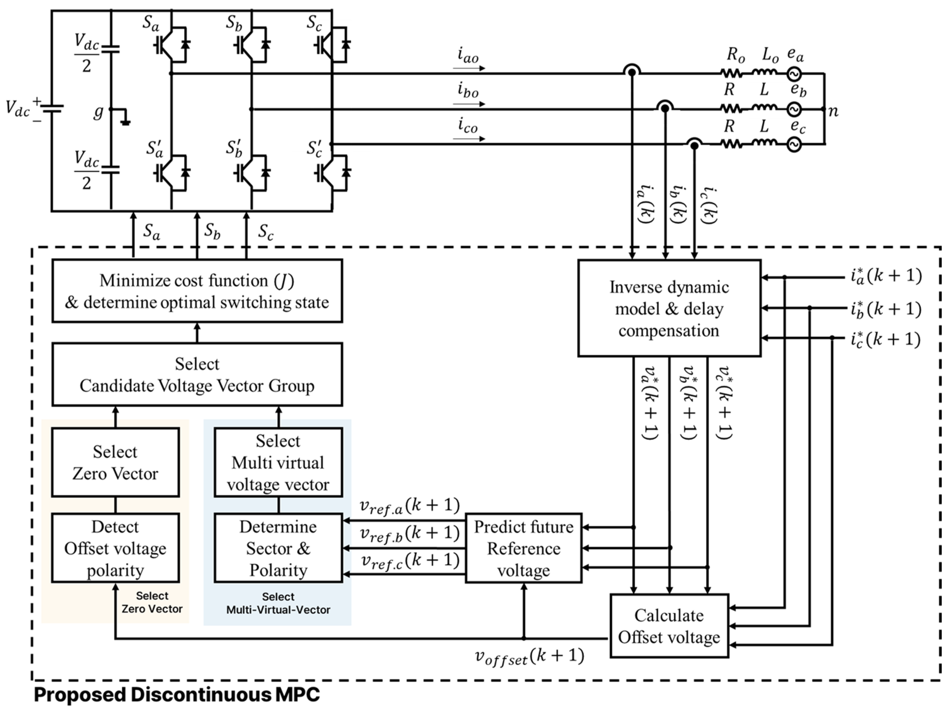
Figure 4 depicts a Block diagram of the proposed D-MPC.
Switching losses are proportional to the magnitude of the load current flowing through the inverter leg during switching. The proposed D-MPC applies discontinuous switching by determining sections with the highest current and voltage magnitudes. By adding an offset voltage to the future reference voltage, the voltage in the maximum current sections is fixed at +Vdc/2 or −Vdc/2. The switching losses are reduced by clamping the phase with the maximum current to either a positive or a negative DC link.
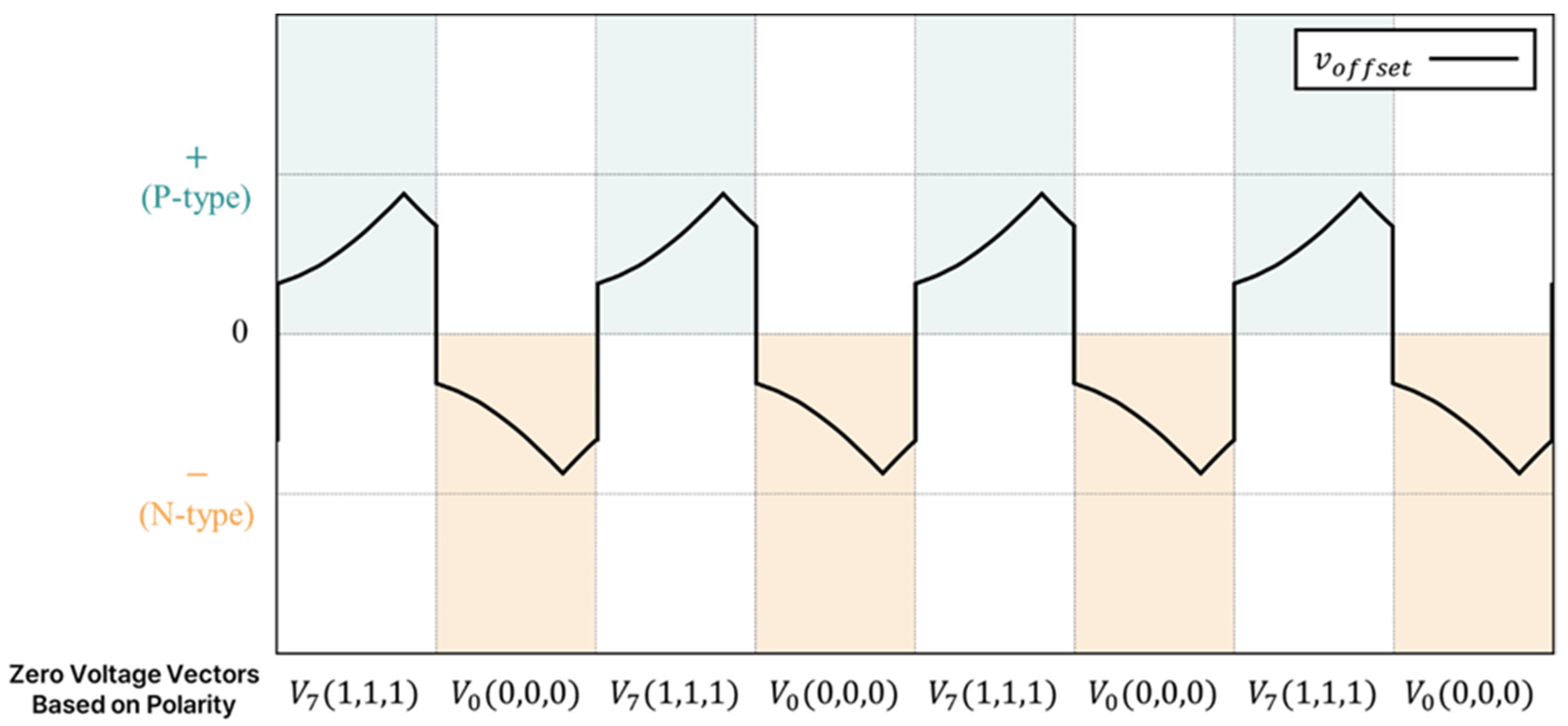
Additionally, the proposed method selects an optimal zero-voltage vector by utilizing the offset voltage polarity. Although the zero-voltage vectors, V7 and V0, share the same magnitude of zero, their switching states vary as (111) and (000), respectively. The improper selection of zero-voltage vectors can cause unnecessary switching, thereby increasing the losses or creating nonoptimal discontinuous intervals. Therefore, the appropriate selection of zero-voltage switching states is crucial for reducing the switching losses.
The offset voltage for clamping is calculated based on the voltage and current magnitudes. When the polarity of the calculated offset voltage is positive (+), V7(111) is used as the zero-voltage vector; whereas, when it is negative (−), V0(000) is used. Selecting the appropriate zero-voltage vectors according to the offset voltage polarity helps in maintaining the switching state of the already clamped phase, thereby preventing additional switching losses.
This selection of zero-voltage vectors affects both the switching losses and MVVV generation. Zero-voltage vectors are essential for generating MVVVs. Since different zero-voltage vectors are used based on the offset voltage polarity, the multi-virtual vectors are also distinguished based on the polarity.
The vectors generated via this process form the candidate voltage group. The optimal voltage vector that minimizes the difference from the calculated reference voltage is determined using a cost function. The desired load current is tracked by applying the switching state corresponding to the inverter.
In summary, the proposed D-MPC presents a balanced performance by reducing the current error and distortion while improving the overall power conversion efficiency.
The proposed method constructs a voltage-based cost function. The output phase voltage of the inverter at the next sampling point, calculated based on Equation (6) and the inverse dynamic model, is expressed as follows:
v a * k + 1 = 1 T s L o i a o * k + 1 + R o T s L o i a o k + e a k T s v b * k + 1 = 1 T s L o i b o * k + 1 + R o T s L o i b o k + e b k T s v c * k + 1 = 1 T s L o i c o * k + 1 + R o T s L o i c o k + e c k T s
where v a * k + 1 , v b * k + 1 , and v c * k + 1 denote the inverter output phase voltages at the next sampling point, and i a o * k + 1 , i b o * k + 1 , and i c o * k + 1 denote the inverter output phase currents at the next sampling point, respectively.
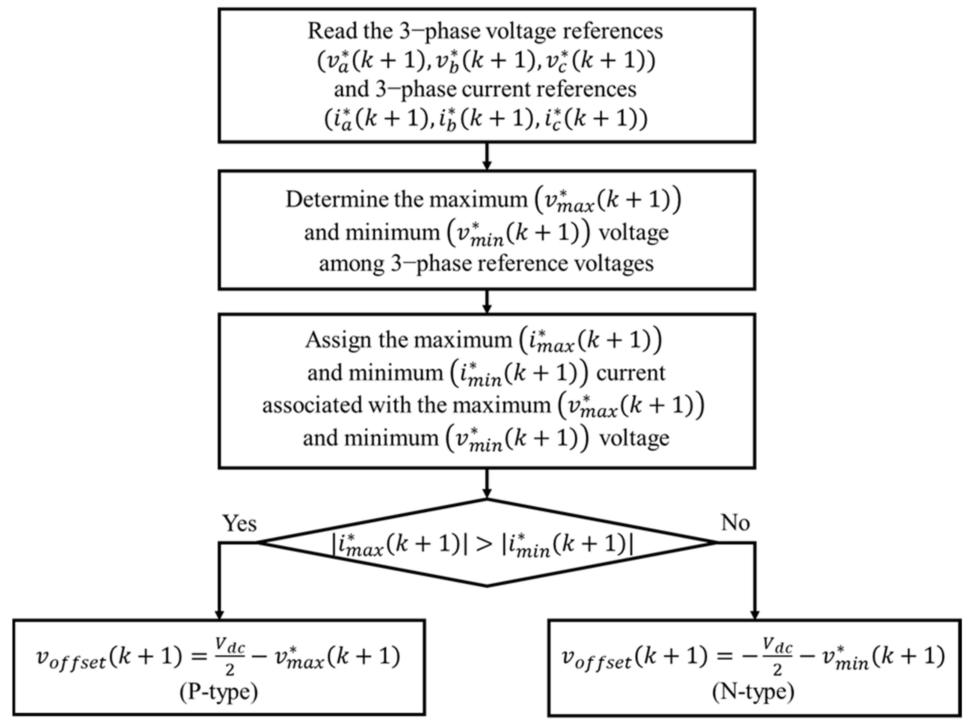
The discontinuous switching intervals are determined based on the voltage and current magnitudes. The maximum and minimum reference voltages calculated using Equation (8) are calculated as follows:
v m a x * ( k + 1 ) = max   ( v a * ( k + 1 ) , v b * ( k + 1 ) , v c * ( k + 1 ) ) v m i n * ( k + 1 ) = min   ( v a * ( k + 1 ) , v b * ( k + 1 ) , v c * ( k + 1 ) )
where v m a x * ( k + 1 ) denotes the maximum voltage, and v m i n * ( k + 1 ) denotes the minimum voltage, respectively.
Subsequently, the currents flowing in the phases where these two voltages occur are identified and designated as the maximum and minimum currents, respectively. In particular, the current in the phase where v m a x * k + 1 occurs is assigned as i m a x * k + 1 , whereas the current in the phase where v m i n * k + 1 occurs is assigned as i m i n * k + 1 . If the absolute value of i m a x * k + 1 exceeds that of i m i n * k + 1 , the offset voltage polarity becomes positive; otherwise, it becomes negative. The offset voltage is calculated as follows:
v o f f s e t k + 1 =     V d c 2 v m a x * k + 1 ,             i f   i m a x * k + 1 > i m i n * k + 1       V d c 2 v m i n * k + 1 ,       i f   i m i n * k + 1 > i m a x * k + 1  
where v o f f s e t k + 1 denotes the offset voltage.
When its polarity is positive (+), it is defined as a P-type offset voltage, and when it is negative (−), it is defined as an N-type offset voltage. The calculated offset voltage is added to the future reference voltage to clamp the phase with a high current to either a positive or negative DC link. Figure 5 depicts the calculation process of the offset voltage.
In the proposed method, V7(111) is selected when the offset voltage is P-type, and V0(000) is selected when it is N-type. Figure 6 depicts the selection of the zero-voltage vectors based on the offset voltage polarity.
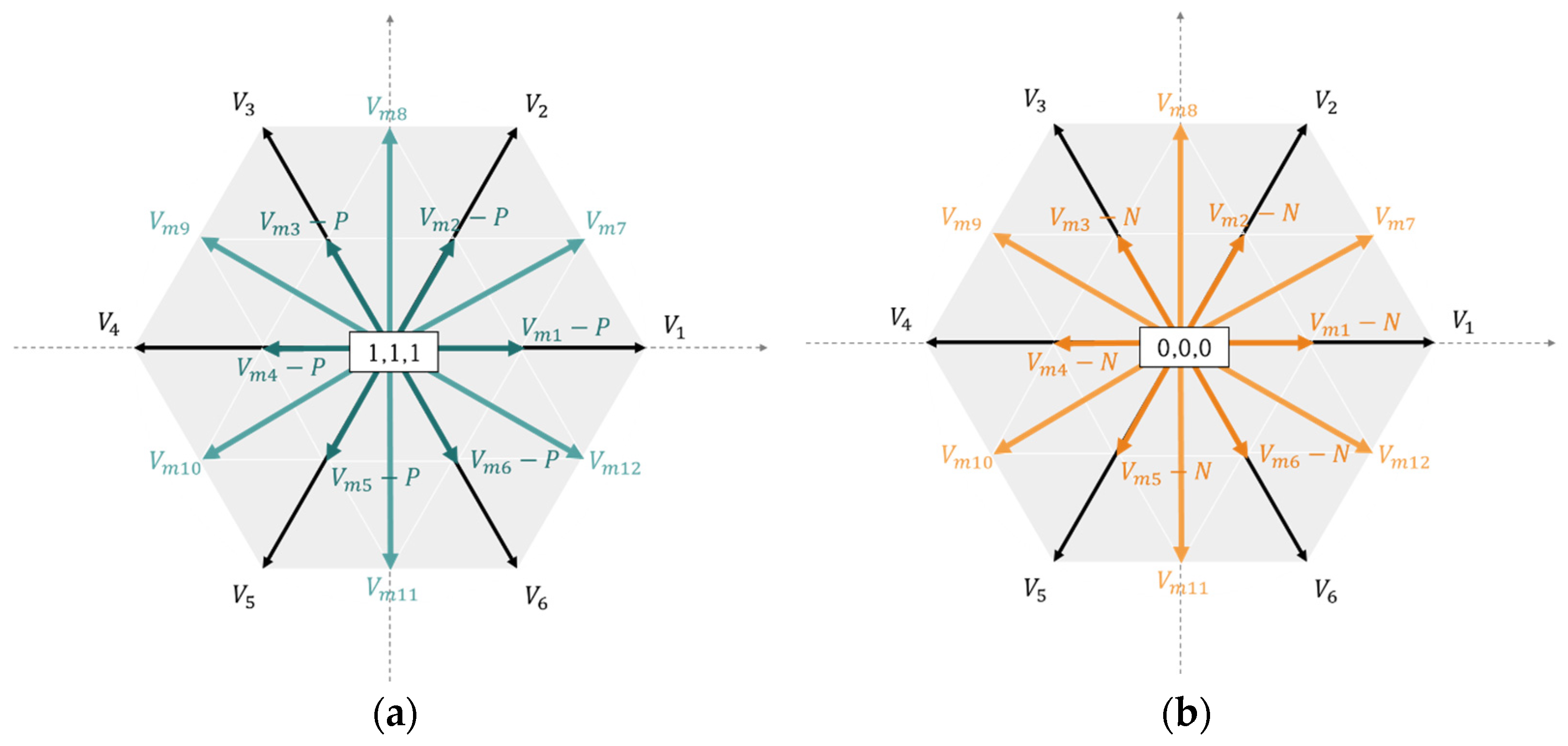
This selection of the zero-voltage vectors affects the switching losses and alters the switching states of the considered MVVVs. For the MVVV, V m 1 ~ V m 6 , the zero-voltage vectors, are essential for generation. Therefore, they are classified as P-type and N-type multi-vectors based on the offset voltage polarity. Since V m 7 ~ V m 12 is generated by synthesizing only the active vectors, it is a neutral vector that is unaffected by polarity. Table 1 lists the switching states of the inverters used in the proposed method.
Figure 7 depicts a vector diagram of the multi-virtual voltage vectors based on the offset polarity.
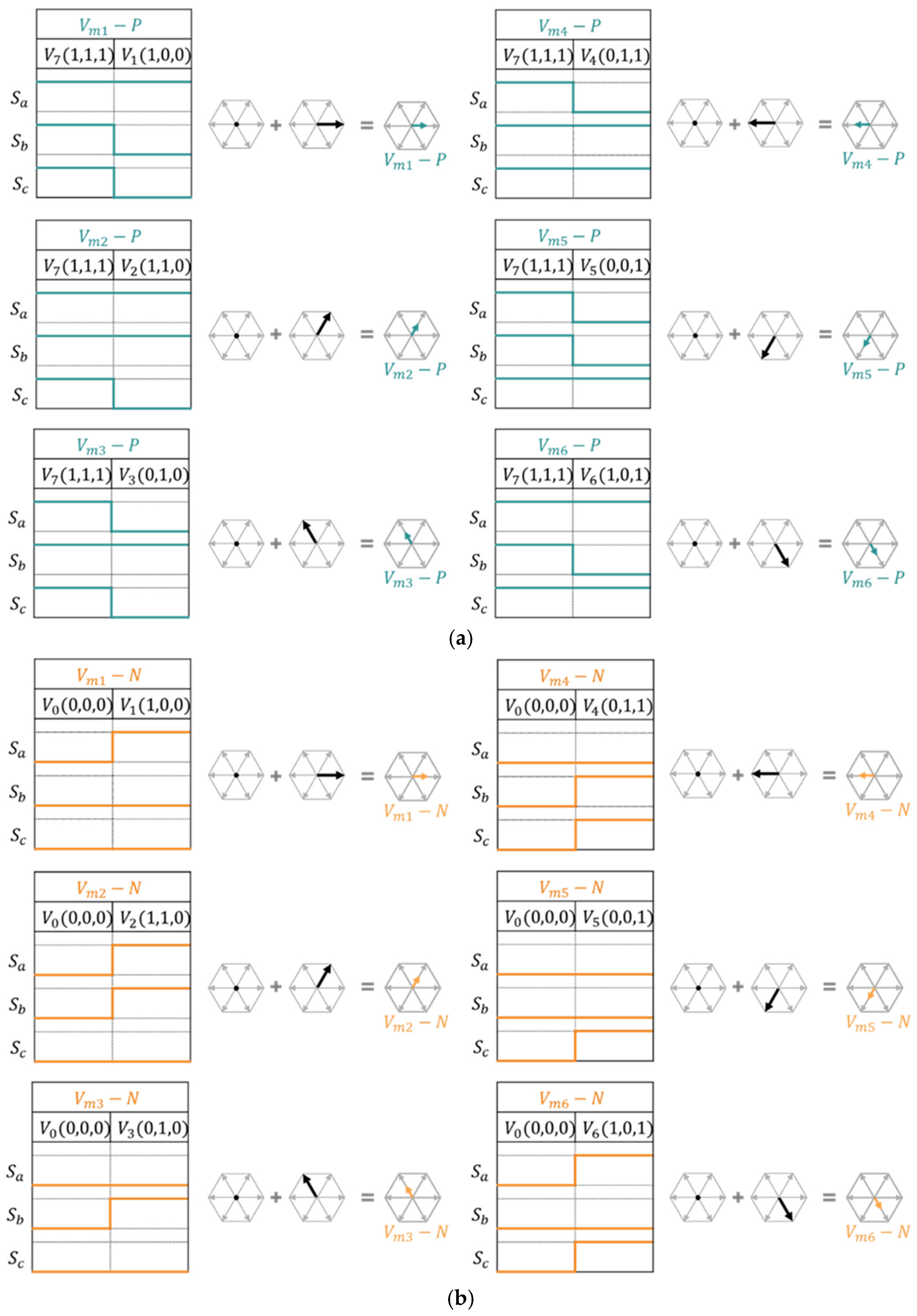
Figure 8 depicts the detailed switching states and generation process of P-type and N-type multi-vectors based on the selected zero-voltage vector.
The reference voltage for discontinuous switching can be calculated by adding the offset voltage to the voltage vector determined using Equation (8) as follows:
v r e f . x ( k + 1 ) = v x * ( k + 1 ) + v o f f s e t ( k + 1 )     ( x = a ,   b ,   c )
The optimal switching state is determined by comparing the reference voltage vector with the candidate vectors listed in Table 1 using a cost function. The cost function is expressed as follows:
J = v r e f . x ( k + 1 ) T s v x ( k + 1 ) T s     ( x = a ,   b ,   c )

4. Simulations and Experimental Results

The performance of the proposed method is analyzed via simulations using an input DC voltage (Vdc = 200 V) and RL load (R = 1.2 Ω, L = 9.87 mH). The reference current is set to 15 A based on a modulation index of 0.6, and Table 2 summarizes the parameters used in the simulation.
The performance of the proposed method is validated via comparative analyses with an existing MPC. The MPCs used in these analyses are given below.
The first is the conventional MPC. This approach utilizes six active voltage vectors and two zero-voltage vectors for current control in two-level inverters. However, its performance is limited by the number of available voltage vectors.
The second is the multi-vector MPC. This approach enhances the conventional MPC by introducing a multi-vector concept. While it achieves an output performance similar to that of multi-level inverters with improved current quality, it suffers from increased switching frequency and consequential switching losses owing to the higher number of voltage vectors under consideration.
To overcome these limitations, we propose the multi-vector-based D-MPC in this study. The proposed method integrates the multi-vector approach with discontinuous control techniques to preserve the output performance while suppressing switching during specific current intervals. This approach reduces the switching losses and improves the inverter efficiency.
This study verifies that the proposed D-MPC maintains the output performance while reducing the losses when compared with the conventional MPC and multi-vector MPC. We conducted simulations and experiments under both steady-state and transient conditions.
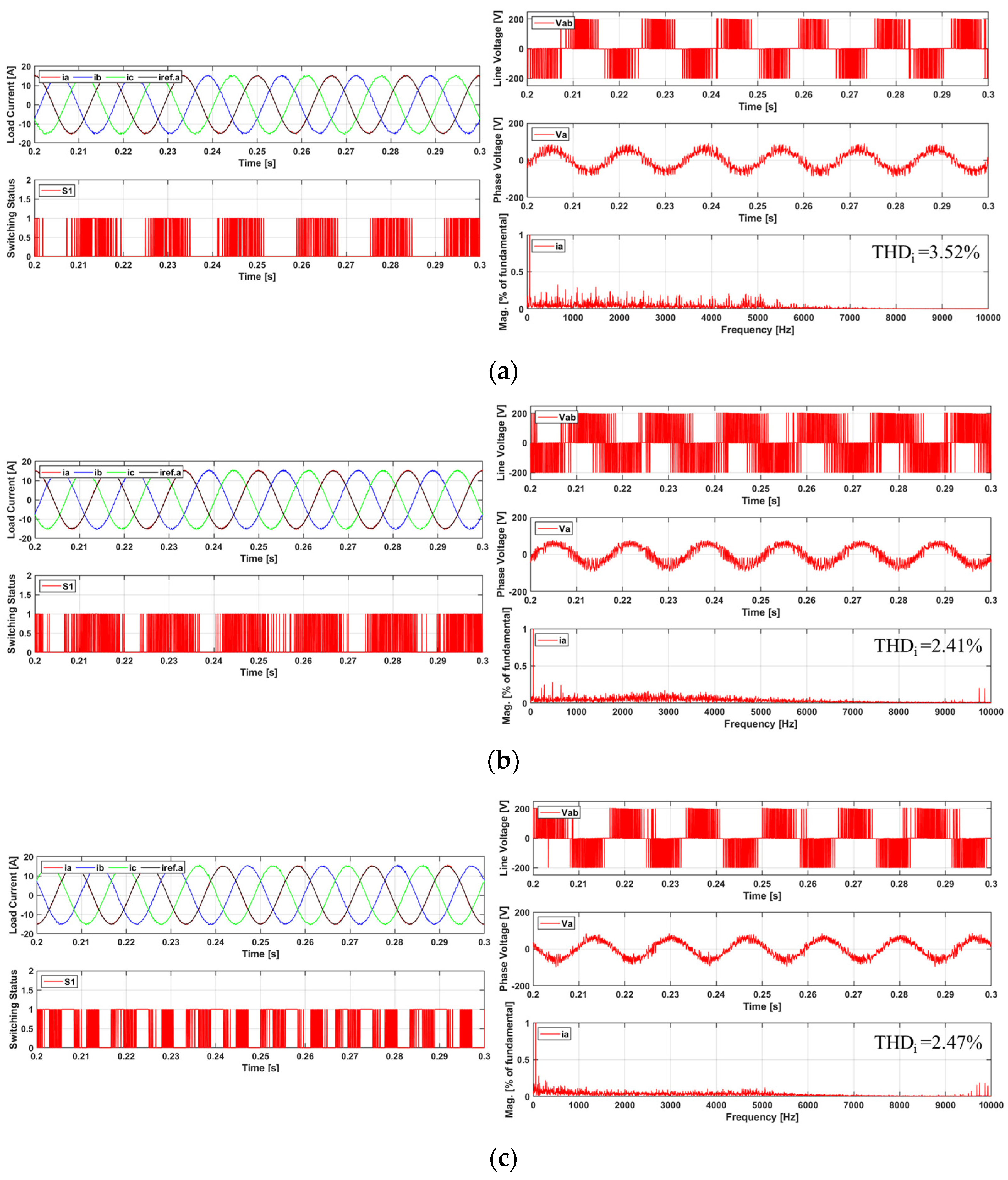
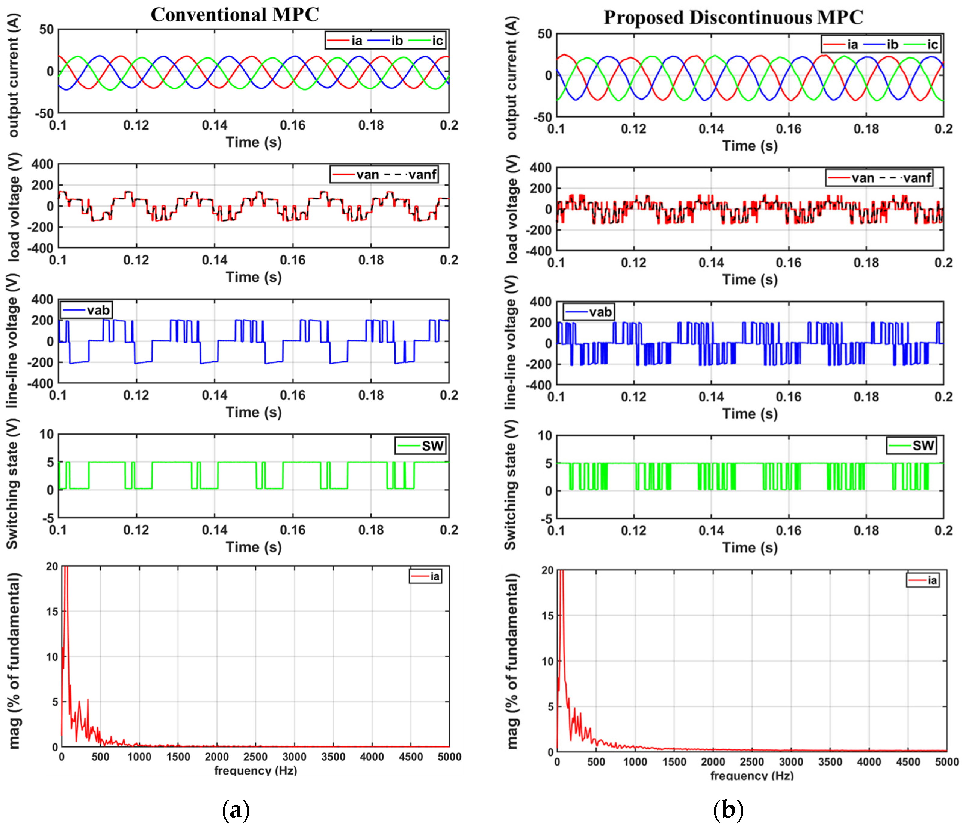
We performed a comparative performance analysis for the conventional MPC and multi-vector MPC, and we proposed D-MPC under normal operating conditions (Figure 9). The comparison metrics include three-phase output currents, phase A reference current, switching waveforms for the phase A leg, line-to-line voltages, load phase voltages, and THD.
The results indicate that the conventional MPC exhibited relatively lower quality in three-phase output currents, with phase voltages presenting significant deviations from the ideal sinusoidal waveforms. This indicates the limitations of the basic implementation of the predictive control strategy.
The multi-vector MPC exhibited improved three-phase output current quality when compared with the conventional MPC by utilizing multiple vectors. The phase voltages also exhibited a closer approximation to the sinusoidal waveforms. However, this approach faces a significant drawback in that an increased switching frequency presents higher switching losses, which reduces the overall electric propulsion ship system efficiency.
The proposed D-MPC method exhibited additional improvements. The fast Fourier transform (FFT) analysis of the phase A output current demonstrated that the proposed method presented lower THD when compared with the conventional MPC, while maintaining THD performance equivalent to that of the multi-vector MPC.
Although direct confirmation of the switching losses from the graphs is challenging, the analysis of the switching patterns demonstrated suppressed switching activity during periods of high currents. This indicates a potential reduction in the switching losses, which was subsequently verified via additional data analysis, as shown in Figure 10.
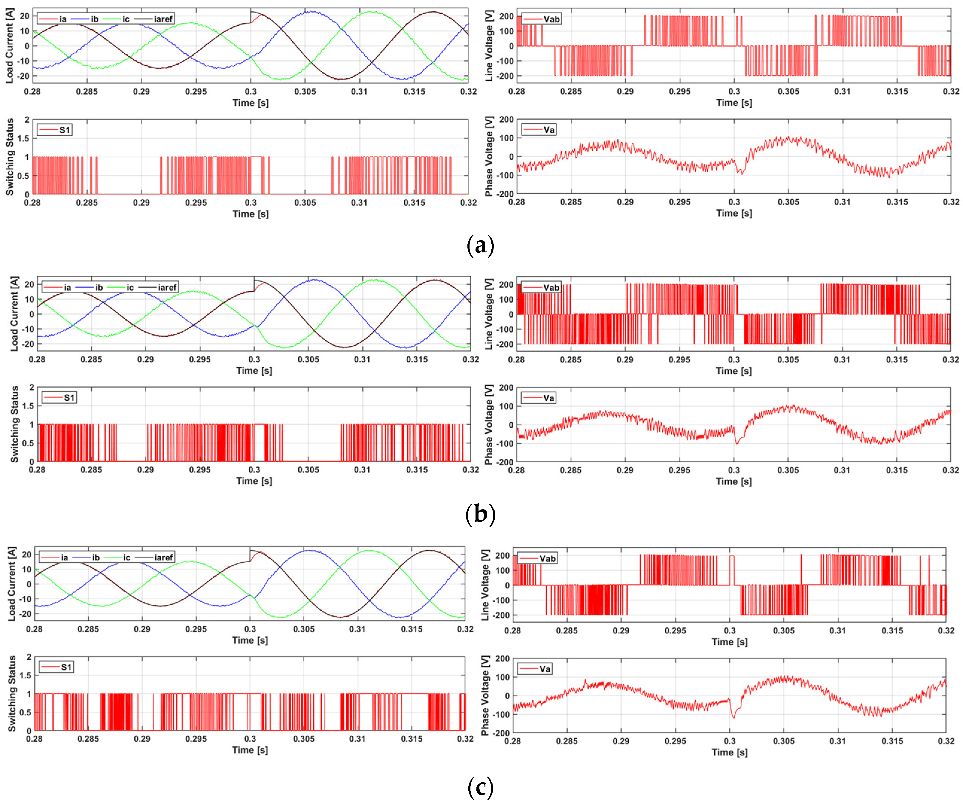
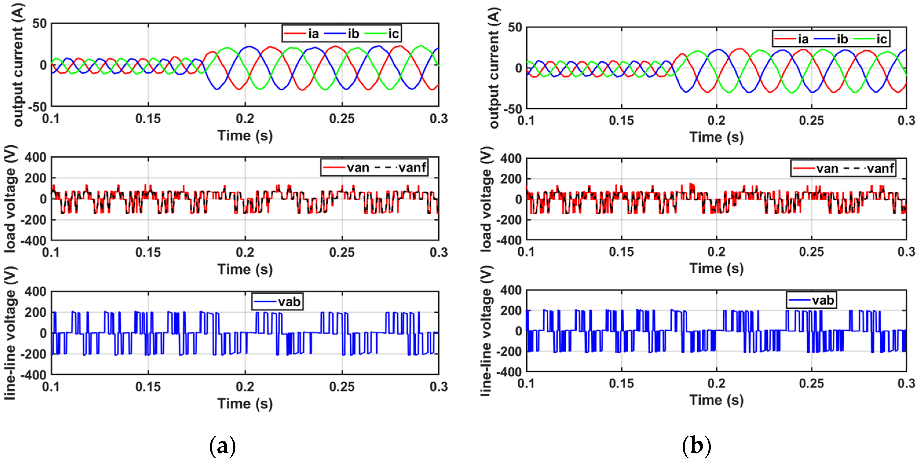
The output performance of the conventional MPC, multi-vector MPC, and the proposed D-MPC was compared during the transient states by varying the output current, as shown in Figure 11. The comparison criteria are identical to those used in the steady-state analysis.
The conventional MPC exhibited rapid response characteristics; however, it demonstrated a relatively lower output current quality.
The multi-vector MPC demonstrated improved output performance when compared with the conventional MPC using multiple vectors, but it presented increased losses due to higher switching frequency.
The proposed D-MPC achieved rapid response characteristics similar to the conventional MPC while applying multiple vectors and demonstrated that discontinuous intervals are preserved even under low-load conditions. This indicates that a discontinuous control technique can be applied via switching patterns in low-load regions to suppress unnecessary switching operations, thereby potentially reducing the switching losses. Additionally, the output current performance exhibited results similar to those of the multi-vector MPC.
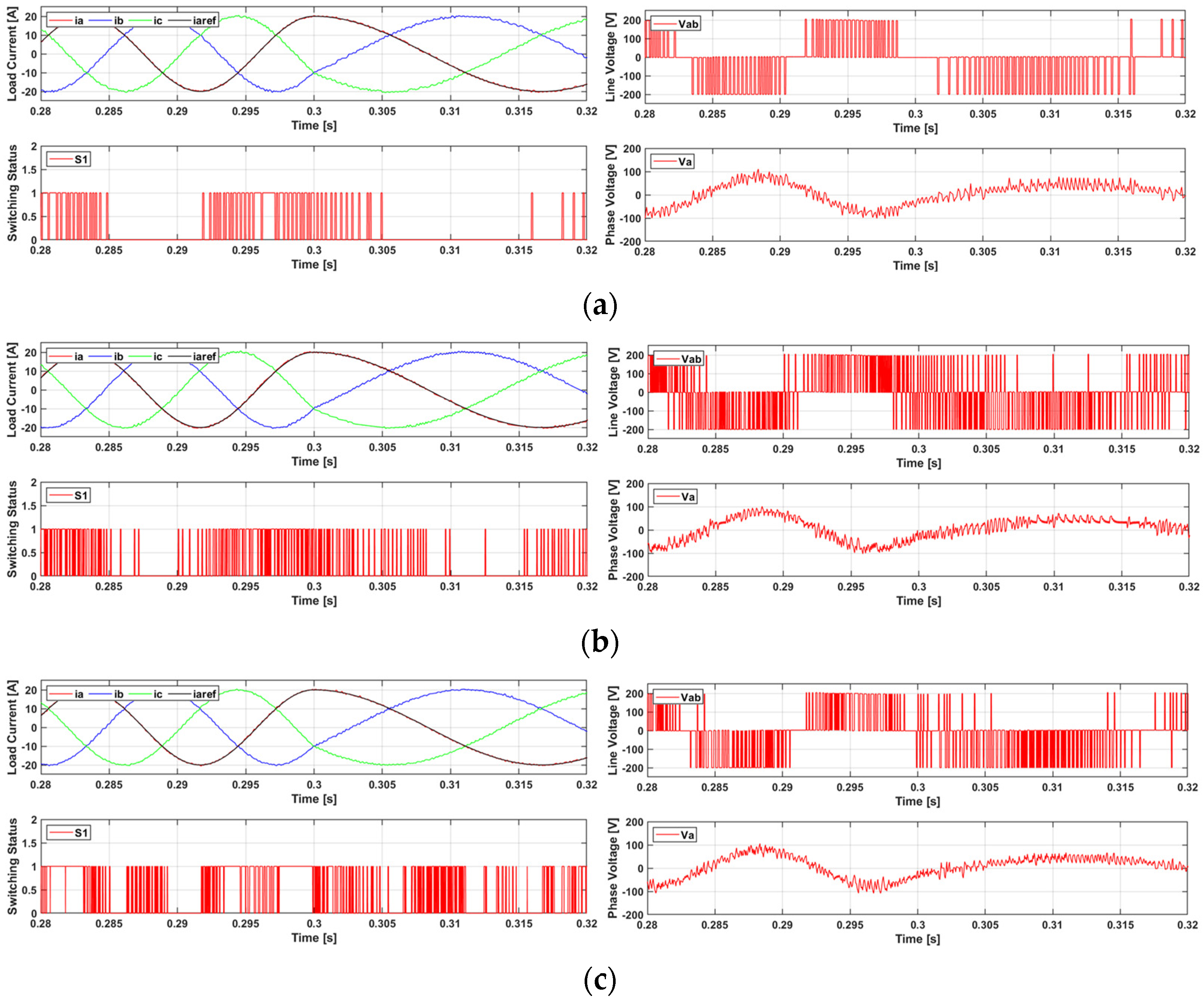
The performances of the conventional MPC, multi-vector MPC, and the proposed D-MPC were compared during the transient states by varying the output frequency, as shown in Figure 12. The comparison criteria were identical to those used in the steady-state analysis.
The conventional MPC exhibited rapid response characteristics; however, it exhibited a tendency towards degraded output current quality under low-frequency conditions.
The multi-vector MPC improved the output performance when compared with the conventional MPC by utilizing multiple vectors; however, this presents the disadvantage of increased switching losses.
The proposed D-MPC exhibited rapid response characteristics similar to those of the conventional MPC while applying multiple vectors and demonstrated superior output current performance even under low-frequency conditions. Furthermore, the discontinuous switching intervals were consistently maintained in the high-current regions, regardless of the frequency variations. This demonstrates that the discontinuous control technique presents consistent switching suppression effects independent of the frequency changes, thereby preventing unnecessary switching operations and reducing the switching losses.
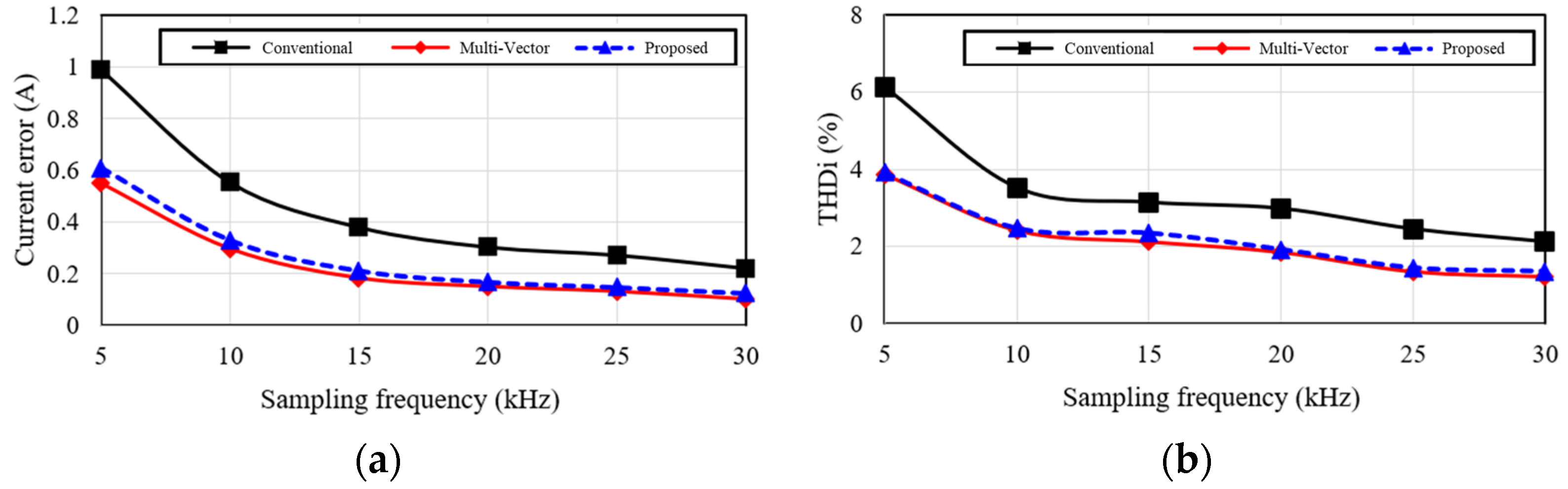
We performed a comparative analysis for the conventional MPC, multi-vector MPC, and the proposed D-MPC across various sampling frequency conditions, as shown in Figure 10. Figure 10a presents a comparison of the current error performances of each method. The current error is calculated as follows:
e r r o r i x = 1 N k = 1 N i x . r e f i x o   ( x = a . b . c )
where i x . r e f denotes the reference currents for each phase, and i x o denotes the measured load currents. With N set to 10,000, the error represents the average of these values.
The proposed D-MPC method presents a lower current error when compared with the conventional MPC across all the sampling frequency ranges, despite implementing multiple vectors. When compared with the multi-vector MPC, the proposed method achieves a nearly identical output performance while effectively reducing the current error by employing its discontinuous switching technique. In particular, the proposed method presents considerable potential for improving the system efficiency owing to reduced switching losses, achieved via switching suppression in the discontinuous regions.
Additionally, Figure 10b depicts the comparison of the output current THD for each method. The THD output current is calculated as follows:
% T H D i = i x 2 2 + i x 3 2 + + i x n 2 i x 1   ( x = a , b , c )
where i x 1 i x n denote the fundamental and nth harmonic components of the output currents in phase x , respectively. The simulation considers up to the 8335th harmonic components.
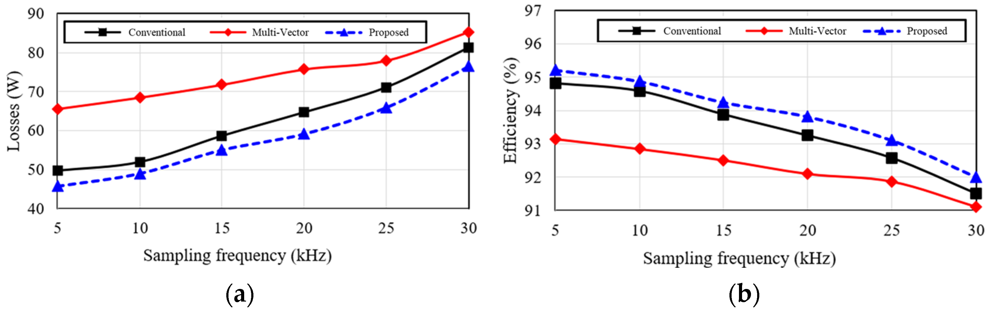
We performed comparative analyses of the total losses and for the conventional MPC, multi-vector MPC, and the proposed D-MPC across various switching frequency conditions, as shown in Figure 13. The proposed D-MPC presented lower losses and higher efficiency than the conventional MPC at identical switching frequencies. This improvement is attributed to the fact that the conventional MPC increases the number of switching operations during the periods of increasing current, whereas the proposed D-MPC employs discontinuous switching techniques that suppress the switching operations during unnecessary intervals. Furthermore, when compared with the multi-vector MPC, the proposed method maintained the output performance while further reducing the switching losses, achieving greater efficiency improvement.
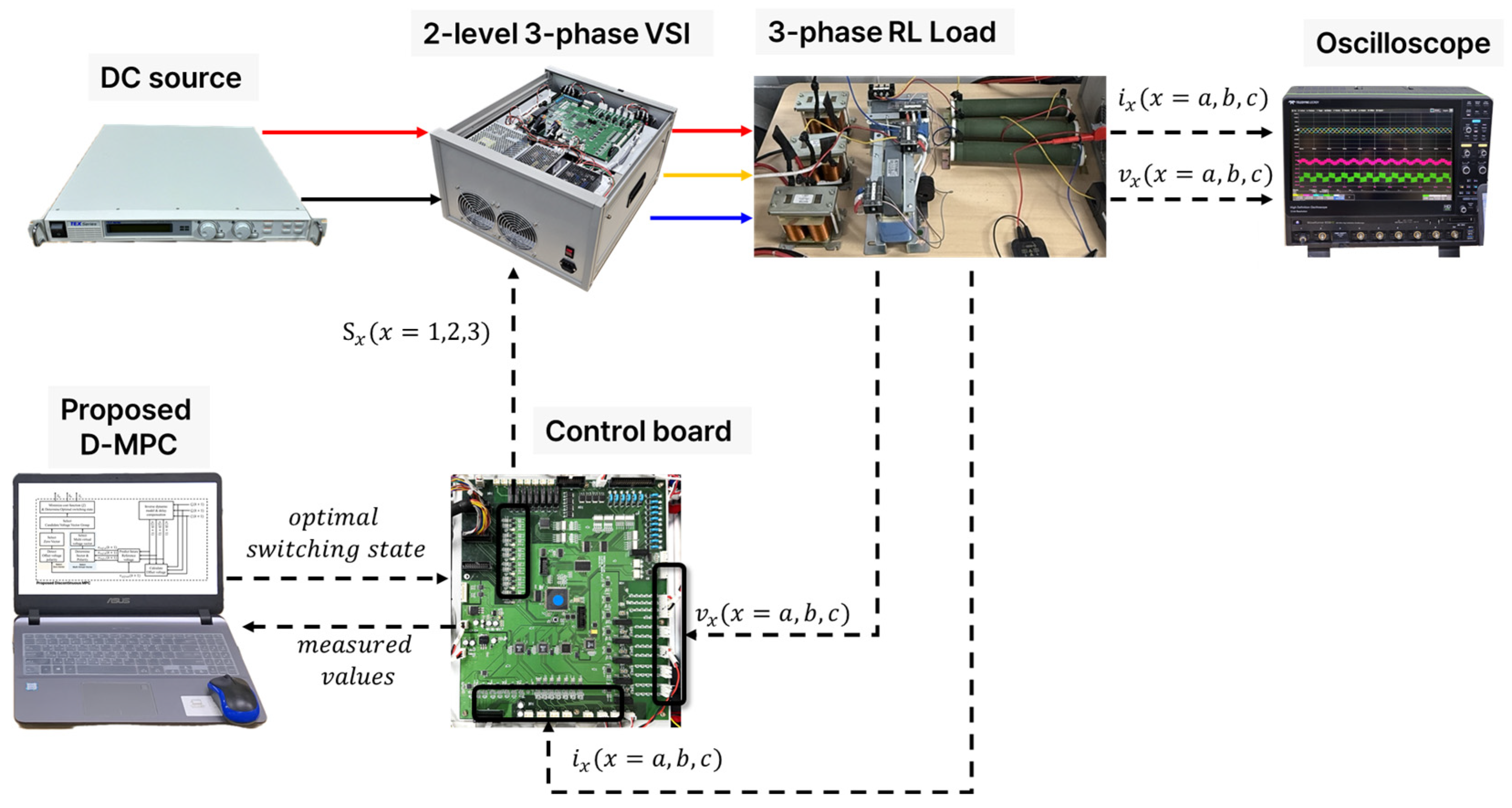
The proposed method was implemented using a prototype experimental setup, as shown in Figure 14. The experimental apparatus comprised a three-phase voltage source inverter (VSI) with IGBT modules and an RL load. A digital signal processor (DSP, TMS320F28335) was used for the real-time processing of the switching algorithm.
In this experiment, we validated the performance of the proposed method via comparison with conventional MPCs. We conducted experiments to demonstrate that the proposed method can maintain the output current performance while reducing the switching losses and improving inverter efficiency via discontinuous switching techniques. In addition, the performance was evaluated under various switching frequencies and load conditions to examine the feasibility of its practical implementation in real-world environments.
The experimental results (Figure 15 and Figure 16) demonstrate the superior performance of the proposed discontinuous MPC compared with the conventional MPC. Notably, the results exhibit the same trends as those observed in the simulation, confirming consistent improvements under both steady-state (Figure 15) and transient-state (Figure 16) conditions.
The output performance of the proposed MPC was maintained at nearly identical levels to that of the multi-vector MPC. However, by implementing discontinuous-based switching techniques, experimental validation confirmed that switching losses can be potentially reduced, thereby increasing the inverter efficiency.
Table 3 presents a comparison of the DSP execution times and reduction rates for the conventional MPC, multi-vector MPC, and the proposed D-MPC. The proposed method achieved an execution time of 20.12 μs, which demonstrates an improvement of approximately 20% when compared with the conventional MPC (25.23 μs). This efficiency is quantified by a DSP execution time reduction rate of 0.79, exhibiting enhanced computational efficiency over the existing method. Furthermore, the execution time of the proposed method is similar to that of the multi-vector MPC (19.34 μs).
Despite implementing multiple vectors, the introduction of the pre-vector selection technique enabled the proposed method to maintain an efficient execution time comparable to that of the existing methods. These experimental results demonstrate that the combination of discontinuous switching and pre-vector selection can minimize the computational overhead while maintaining the control performance. The proposed D-MPC balances the processing efficiency with the control accuracy.
Table 4 presents a comparison of the losses and efficiency of the conventional MPC, multi-vector MPC, and proposed D-MPC under a 5 kW load condition.
The experimental results demonstrate that the proposed MPC achieved lower losses at 260 W, demonstrating an improvement of approximately 15% when compared with the conventional MPC (307.5 W). When compared with the multi-vector MPC (344 W), the proposed method reduced the losses by 24%, indicating a significant improvement in the performance.
In terms of efficiency, the proposed MPC exhibited superior results at 95%, outperforming both the conventional MPC (94%) and multi-vector MPC (93%).
These experimental findings demonstrate that discontinuous switching effectively reduces the switching losses by suppressing the switching operations during high-current periods. Furthermore, the results indicate that selecting the optimal zero-voltage vectors based on the offset voltage polarity prevents unnecessary switching, making it an effective methodology for improving both the loss reduction and electric propulsion system efficiency.

5. Conclusions

In this study, we propose a D-MPC approach to enhance the performance of the inverters used in electric propulsion ships. The proposed method maintains the power quality improvements of the multi-vector MPC while minimizing the switching losses via discontinuous modulation and optimized zero-voltage vector selection. The simulation and experimental results demonstrate the superior performance of the D-MPC method when compared with the conventional MPC and multi-vector MPC approaches.
The proposed method employs discontinuous switching in high-current regions to reduce the switching losses, and it selects the optimal zero-voltage vector based on the offset voltage polarity to suppress unnecessary switching operations. Using this approach, the proposed method achieves an improved THD performance of up to 30%. The current error is also reduced by 30–45% based on the sampling frequency, with significant improvements observed under lower sampling frequency conditions (5–10 kHz).
While maintaining a current quality similar to that of the multi-vector MPC, the proposed method achieves substantial loss reductions of approximately 15% when compared with the conventional MPC and 24% when compared with that of the multi-vector MPC. A consistent pattern of lower switching losses and higher inverter efficiency was observed under various switching frequency conditions.
Furthermore, the D-MPC approach reduces the computational overhead by limiting the number of switching state options via discontinuous interval settings. The DSP execution time of the proposed method decreases by approximately 20% when compared with that of conventional MPC, while maintaining a performance level similar to that of the multi-vector MPC, thereby ensuring the ease of real-time implementation. This ensures the feasibility of real-time implementation.
The findings of this study present considerable technical advantages for power conversion devices operating in environments with limited cooling systems, such as small- to medium-sized vessels. By simultaneously enhancing the inverter efficiency, control performance, and implementation simplicity, the proposed D-MPC contributes to the advancement of inverter control technology for electric propulsion ships. Furthermore, it presents considerable potential for applications in various industrial fields where power conversion is critical.
Future plans include long-term performance verification through maritime demonstration on actual small- and medium-sized electric propulsion vessels and the optimization of overall electric propulsion system efficiency through integration with energy storage systems.

Author Contributions

Methodology, C.R.; software, E.-c.S.; investigation, H.-g.C.; data curation, E.-c.S.; writing—original draft, C.R. and H.-g.C.; writing—review and editing, C.R.; supervision, C.R.; project administration, C.R. All authors have read and agreed to the published version of the manuscript.

Funding

This research was funded by the Ministry of Trade, Industry and Energy (MOTIE) and the Korea Evaluation Institute of Industrial Technology (KEIT), grant numbers RS-2024-00437087 and RS-2024-00432064.

Institutional Review Board Statement

Not applicable.

Informed Consent Statement

Not applicable.

Data Availability Statement

The original contributions presented in this study are included in the article. Further inquiries can be directed to the corresponding author.

Conflicts of Interest

The authors declare no conflicts of interest.

Abbreviations

The following abbreviations are used in this manuscript:
D-MPCdiscontinuous model predictive control
DSPsdigital signal processors
FCS-MPCFinite control set-model predictive control
FFTfast Fourier transform
FLCfuzzy logic control
IEAInternational Energy Agency
IMOInternational Maritime Organization
MPCmodel predictive control
MVVVmulti-virtual-voltage vectors
PIproportional-integral
SMCsliding mode control
SVPWMspace-vector pulse width modulation
THDtotal harmonic distortion
VSIvoltage source inverter

References

  1. Roškova, Z.; Schneider, J.; Štengel, M. Predicted Hydrofluorocarbon (HFC) and Perfluorocarbon (PFC) Emissions for the Years 2010–2050 in the Czech Republic. Atmosphere 2023, 14, 111. [Google Scholar] [CrossRef]
  2. Reguero, B.; Losada, I.; Méndez, F.J. A Global Wave Power Resource and its Seasonal, Interannual and Long-Term Variability. Appl. Energy 2015, 148, 366–380. [Google Scholar] [CrossRef]
  3. World Resources Institute. Historical GHG Emissions. In Climate Watch Data; World Resources Institute: Washington, DC, USA, 2024; Available online: https://www.climatewatchdata.org/ghg-emissions (accessed on 16 January 2024).
  4. Taveira-Pinto, F.; Rosa-Santos, P.; Fazeres-Ferradosa, T. Marine Renewable Energy. Renew. Energy 2020, 150, 1160–1164. [Google Scholar] [CrossRef]
  5. IMO. Initial IMO GHG Strategy; IMO: London, UK, 2023; Available online: https://www.imo.org/en/MediaCentre/HotTopics/Pages/Reducing-greenhouse-gas-emissions-from-ships.aspx (accessed on 11 May 2025).
  6. Korea Trade-Investment Promotion Agency. Global Eco-Friendly Marine Equipment Market Trends and Overseas Market Entry Strategies; Korea Trade-Investment Promotion Agency: Seoul, Republic of Korea, 2019; Available online: https://dl.kotra.or.kr/pyxis-api/2/digital-files/c16960f0-0489-018a-e053-b46464899664 (accessed on 11 May 2025).
  7. Jung, J.Y.; Jeon, H.M.; Kim, H.M.; Kim, S.W. A Novel Approach for the Systematic Evaluation and Optimization of Performance and Emissions in Hybrid Electric Propulsion Systems. J. Mar. Sci. Eng. 2025, 13, 328. [Google Scholar] [CrossRef]
  8. Lee, Y.W.; Kim, J.S.; Jeon, H.M.; Kim, S.W.; Kim, H.M. Regulatory improvement of a marine electric propulsion system based on an IEC standard and domestic–foreign classification rules. J. Mar. Eng. Technol. 2024, 1–11. [Google Scholar] [CrossRef]
  9. Kim, H.C.; Kim, J.S. Development and Validation of Reliability Testing Methods for Insulation Systems in High-Voltage Rotating Electrical Machinery on Ships. J. Mar. Sci. Eng. 2025, 13, 186. [Google Scholar] [CrossRef]
  10. Kim, H.M.; Kim, J.S. Research on Improving Energy Efficiency Through Optimal Load Control Between a Ship’s Shaft Generator and Diesel Generator. IEEE Access 2024, 12, 156745–156764. [Google Scholar] [CrossRef]
  11. Protection of the Arctic Marine Environment (PAME). Alternative Fuels in the Arctic; Arctic Council Secretariat: Tromsø, Norway, 2019; p. 30. [Google Scholar]
  12. Kim, J.R. An Empirical Study on the Energy Saving of Battery Electric Propulsion Ships. Master’s Thesis, Korea Maritime and Ocean University, Busan, Republic of Korea, February 2019. [Google Scholar]
  13. Lee, C.H. Technical Trends of Eco-friendly Electric Ships and Structure of Marine Electric Propulsion Systems. Trans. Korean Inst. Power Electron. 2022, 27, 52–57. [Google Scholar]
  14. McCoy, T. Trends in Ship Electric Propulsion. In Proceedings of the IEEE Power Engineering Society Summer Meeting, Chicago, IL, USA, 21–25 July 2002; pp. 343–346. [Google Scholar] [CrossRef]
  15. Reigosa, P.D.; Wang, H.; Yang, Y.; Blaabjerg, F. Prediction of Bond Wire Fatigue of IGBTs in a PV Inverter Under a Long-Term Operation. IEEE Trans. Power Electron. 2016, 31, 7171–7182. [Google Scholar]
  16. Roh, C.; Jeon, H.M.; Kim, S.W.; Kim, J.S.; Lee, N.Y.; Song, S.W. Optimal hybrid pulse width modulation for three-phase inverters in electric propulsion ships. Machines 2024, 12, 109. [Google Scholar] [CrossRef]
  17. Kim, H. Improving Electric Power Stability and Efficiency Using an Integrated Control System for Refrigerated Containers. J. Mar. Sci. Eng. 2024, 12, 1624. [Google Scholar] [CrossRef]
  18. Ahmed, A.; Biswas, S.P.; Anower, M.S.; Islam, M.R.; Mondal, S.; Muyeen, S.M. A Hybrid PWM Technique to Improve the Performance of Voltage Source Inverters. IEEE Access 2023, 11, 4717–4729. [Google Scholar] [CrossRef]
  19. Bouri, S.; Boudaoud, T.; Boudjelal, T. PI controller for controlling a three-phase inverter of a PV system connected to the electrical network. Acta Electrotech. Et. Inf. 2021, 21, 11–18. [Google Scholar] [CrossRef]
  20. Cherati, S.M.; Azli, N.A.; Ayob, S.M.; Mortezaei, A. Design of a current mode PI controller for a single-phase PWM inverter. In Proceedings of the 2011 IEEE Applied Power Electronics Colloquium (IAPEC), Johor Bahru, Malaysia, 18–19 April 2011; pp. 180–184. [Google Scholar] [CrossRef]
  21. Abdolrasol, M.G.M.; Hannan, M.A.; Hussain, S.M.S.; Ustun, T.S. Optimal PI controller based PSO optimization for PV inverter using SPWM techniques. Energy Rep. 2022, 8, 1003–1011. [Google Scholar] [CrossRef]
  22. Yang, Y.; Wang, Y.; Zhang, W.; Li, Z.; Liang, R. Design of adaptive fuzzy sliding-mode control for high-performance islanded inverter in micro-grid. Energies 2022, 15, 9154. [Google Scholar] [CrossRef]
  23. Xiao, H.; Zhao, D.; Gao, S.; Spurgeon, S.K. Sliding mode predictive control: A survey. Annu. Rev. Control 2022, 54, 148–166. [Google Scholar] [CrossRef]
  24. Li, H.; Wu, W.; Huang, M.; Chung, H.S.-H.; Liserre, M.; Blaabjerg, F. Design of PWM-SMC Controller Using Linearized Model for Grid-Connected Inverter With LCL Filter. IEEE Trans. Power Electron. 2020, 35, 12773–12786. [Google Scholar] [CrossRef]
  25. Shahdoost, F.T. Adaptive Fuzzy Sliding Mode Based on Model Predictive Control in UAV’s Robot Using Optimized Deep Learning Approach. 2022. Available online: https://www.researchgate.net/publication/361176337_Adaptive_Fuzzy_Sliding_Mode_based_on_Model_Predictive_Control_in_UAV’s_Robot_using_Optimized_Deep_Learning_Approach (accessed on 11 May 2025).
  26. Nguyen, T.V.A.; Dao, Q.T.; Bui, N.T. Optimized fuzzy logic and sliding mode control for stability and disturbance rejection in rotary inverted pendulum. Sci. Rep. 2024, 14, 31116. [Google Scholar] [CrossRef]
  27. Bouguerra, K.; Latreche, S.; Khemliche, M. Comparative Study between IncCond and FLC and SMC Algorithms for MPPT Control for Grid Connected PV System. In Proceedings of the 2024 2nd International Conference on Electrical Engineering and Automatic Control (ICEEAC), Setif, Algeria, 12–14 May 2024; pp. 1–6. [Google Scholar] [CrossRef]
  28. Harbi, I.; Rodriguez, J.; Liegmann, E.; Makhamreh, H.; Heldwein, M.L.; Novak, M.; Kennel, R. Model-predictive control of multilevel inverters: Challenges, recent advances, and trends. IEEE Trans. Power Electron. 2023, 38, 10845–10868. [Google Scholar] [CrossRef]
  29. Vazquez, S.; Rodriguez, J.; Rivera, M.; Franquelo, L.G.; Norambuena, M. Model predictive control for power converters and drives: Advances and trends. IEEE Trans. Ind. Electron. 2016, 64, 935–947. [Google Scholar] [CrossRef]
  30. Roh, C. Optimal selection among various three-phase four-wire back-to-back (BTB) converters with comparative analysis for wave energy converters. Processes 2023, 11, 1463. [Google Scholar] [CrossRef]
  31. Pérez-Guzmán, R.E.; Rivera, M.; Vicencio, N.; Wheeler, P.W. Model predictive control in three-phase inverters. In Proceedings of the 2019 IEEE CHILEAN Conference on Electrical, Electronics Engineering, Information and Communication Technologies (CHILECON), Valparaiso, Chile, 13–27 November 2019; pp. 1–6. [Google Scholar]
  32. Huang, J.; Jiang, G.; Zhang, P.; Chen, J. A Low Switching Frequency Model Predictive Control Method for an Induction Motor Fed by a 3-Level Inverter. Electronics 2023, 12, 3609. [Google Scholar] [CrossRef]
  33. Vargas, R.; Cortés, P.; Ammann, U.; Rodríguez, J.; Pontt, J. Predictive control of a three-phase neutral-point-clamped inverter. IEEE Trans. Ind. Electron. 2007, 54, 2697–2705. [Google Scholar] [CrossRef]
  34. Andino, J.; Ayala, P.; Llanos-Proaño, J.; Naunay, D.; Martinez, W.; Arcos-Aviles, D. Constrained modulated model predictive control for a three-phase three-level voltage source inverter. IEEE Access 2022, 10, 10673–10687. [Google Scholar] [CrossRef]
  35. Chae, H.G.; Roh, C. Enhanced Output Performance of Two-Level Voltage Source Inverters Using Simplified Model Predictive Control with Multi-Virtual-Voltage Vectors. Machines 2024, 12, 781. [Google Scholar] [CrossRef]
  36. Nowicki, M.; Orłowska-Kowalska, T. A zero-voltage-switching current source inverter with three-stage space vector modulation for low-input voltage stand-alone applications. Arch. Electr. Eng. 2024, 73, 941–959. [Google Scholar] [CrossRef]
  37. Beniak, R.; Rogowski, K. A method of reducing switching losses in three-level NPC inverter. Power Electron. Drives 2016, 1, 2. [Google Scholar] [CrossRef]
  38. Novak, M.; Sangwongwanich, A.; Blaabjerg, F. Online optimization of zero-sequence voltage injection of PWM strategy for 3L-NPC converters. In Proceedings of the 2022 International Power Electronics Conference (IPEC-Himeji 2022-ECCE Asia), Himeji, Japan, 15–19 May 2022; pp. 2405–2411. [Google Scholar] [CrossRef]
  39. Nguyen, N.-V.; Nguyen, B.-X.; Lee, H.-H. An Optimized Discontinuous PWM Method to Minimize Switching Loss for Multilevel Inverters. IEEE Trans. Ind. Electron. 2011, 58, 3958–3966. [Google Scholar] [CrossRef]
  40. Wu, Y.; Shafi, M.A.; Knight, A.M.; McMahon, R.A. Comparison of the Effects of Continuous and Discontinuous PWM Schemes on Power Losses of Voltage-Sourced Inverters for Induction Motor Drives. IEEE Trans. Power Electron. 2011, 26, 182–191. [Google Scholar] [CrossRef]
Figure 1. Three-phase two-level inverter configuration with R-L-back EMF.
Applsci 15 05532 g001
Figure 2. Space voltage vector diagram based on the switching states of the three-phase two-level inverter.
Applsci 15 05532 g002
Figure 3. Block diagram of conventional model predictive control (MPC).
Applsci 15 05532 g003
Figure 4. Block diagram of the proposed discontinuous model predictive control (D-MPC).
Applsci 15 05532 g004
Figure 5. Flowchart for offset voltage calculation.
Applsci 15 05532 g005
Figure 6. Zero-voltage vector selection based on offset voltage polarity.
Applsci 15 05532 g006
Figure 7. Vector diagram of multi-virtual voltage vectors (MVVVs) considered by the proposed method based on offset polarity: (a) P-type and (b) N-type.
Applsci 15 05532 g007
Figure 8. Switching states considered by the proposed method based on offset polarity: (a) P-type and (b) N-type.
Applsci 15 05532 g008
Figure 9. Comparison of the output performance of MPC in steady-state operation (three-phase output current, A-phase reference current, line-to-line voltage, load phase voltage, a-phase current (FFT)): (a) conventional MPC, (b) multi-vector MPC, and (c) proposed D-MPC.
Applsci 15 05532 g009
Figure 10. Performance comparison of the conventional MPC, multi-vector MPC, and the proposed D-MPC under varying sampling frequency conditions: (a) current error and (b) output current total harmonic distortion (THD).
Applsci 15 05532 g010
Figure 11. Comparison of the output performance of MPC in the transient-state operation with current magnitude changes from 15 A to 7.5 A (three-phase output current, a-phase reference current, line-to-line voltage, load phase voltage): (a) conventional MPC, (b) multi-vector MPC, and (c) proposed D-MPC.
Applsci 15 05532 g011
Figure 12. Comparison of the output performance of MPC in the transient-state operation with frequency variations from 60 Hz to 30 Hz (three-phase output current, a-phase reference current, line-to-line voltage, load phase voltage): (a) conventional MPC, (b) multi-vector MPC, and (c) proposed D-MPC.
Applsci 15 05532 g012
Figure 13. Performance comparison of the conventional MPC, multi-vector MPC, and the proposed D-MPC under varying switching frequency conditions: (a) total losses and (b) efficiency.
Applsci 15 05532 g013
Figure 14. Experimental setup: photograph and configuration diagram of the prototype for validating the proposed method.
Applsci 15 05532 g014
Figure 15. Steady-state experimental results: comparison of three-phase output currents (20 A), a-phase voltage, line-to-line voltage, and frequency spectrum of a-phase current for MPC methods (a) conventional MPC, and (b) proposed Discontinuous MPC.
Applsci 15 05532 g015
Figure 16. Experimental results of three-phase output currents, line-to-line voltage, a-phase voltage, and frequency spectrum of a-phase current in transient-state with step current (8 A to 20 A) and frequency change (60 Hz to 30 Hz) at 0.2 s: (a) conventional MPC, (b) proposed discontinuous MPC.
Applsci 15 05532 g016
Table 1. Switching states of the inverters used in the proposed method.
Vector
Categories
Vector
Subtypes
Vector StatesSwitching State
(a, b, c)
Stationary Reference Frame Voltage Vector
S 1 S 2 V α V β
Actual voltage vectorZero
vector
V 0 000 0 0
V 7 111 0 0
Active
vector
V 1 100 2 3 V d c 0
V 2 110 1 3 V d c 1 3 V d c
V 3 010 1 3 V d c 1 3 V d c
V 4 011 2 3 V d c 0
V 5 001 1 3 V d c 1 3 V d c
V 6 101 1 3 V d c 1 3 V d c
Multi virtual
voltage vector
P-type
Multi vector
V m 1 P 000100 1 3 V d c 0
V m 2 P 000110 1 6 V d c 1 2 3 V d c
V m 3 P 000010 1 6 V d c 1 2 3 V d c
V m 4 P 000011 1 3 V d c 0
V m 5 P 000001 1 6 V d c 1 2 3 V d c
V m 6 P 000101 1 6 V d c 1 2 3 V d c
N-type
Multi vector
V m 1 N 111100 1 3 V d c 0
V m 2 N 111110 1 6 V d c 1 2 3 V d c
V m 3 N 111010 1 6 V d c 1 2 3 V d c
V m 4 N 111011 1 3 V d c 0
V m 5 N 111001 1 6 V d c 1 2 3 V d c
V m 6 N 111101 1 6 V d c 1 2 3 V d c
Neutral Multi
vector
V m 7 011100 1 2 V d c 3 2 V d c
V m 8 010101 0 V d c
V m 9 110001 1 2 V d c 3 2 V d c
V m 10 100011 1 2 V d c 3 2 V d c
V m 11 101010 0 V d c
V m 12 001110 1 2 V d c 3 2 V d c
Table 2. Simulation parameters.
ParametersValues
Vdc (DC voltage)200 V
Rload (load resistance)1.233 Ω
Lload (load inductance)9.873 mH
Cdc (DC capacitance)4400 µF
Table 3. Comparison of DSP execution time between conventional MPC, multi-vector MPC, and the proposed discontinuous MPC.
Conventional MPCMulti-Vector MPCProposed MPC
Execution time [µs]25.2319.3420.12
Reduction rate of DSP time [−]-0.760.79
Table 4. Comparison of the losses and efficiency between conventional MPC, multi-vector MPC, and the proposed discontinuous MPC (5 kW).
Conventional MPCMulti-Vector MPCProposed MPC
Losses [W]307.5344260
Efficiency [%]93.8593.1294.8
Disclaimer/Publisher’s Note: The statements, opinions and data contained in all publications are solely those of the individual author(s) and contributor(s) and not of MDPI and/or the editor(s). MDPI and/or the editor(s) disclaim responsibility for any injury to people or property resulting from any ideas, methods, instructions or products referred to in the content.

