Article

An Analysis of the Altitude Impact on Roots Compressor Operation for a Fuel Cell System

by
Pedro Piqueras
,
Joaquín de la Morena
*,
Enrique José Sanchis
and
Ibrahim Saadouni
CMT—Clean Mobility & Thermofluids, Universitat Politècnica de València, Camino de Vera s/n, 46022 Valencia, Spain
*
Author to whom correspondence should be addressed.
Appl. Sci. 2025, 15(10), 5513; https://doi.org/10.3390/app15105513
Submission received: 9 April 2025 / Revised: 10 May 2025 / Accepted: 12 May 2025 / Published: 14 May 2025
(This article belongs to the Special Issue Advances in Fuel Cell Renewable Hybrid Power Systems)

Abstract

Hydrogen fuel cell vehicles are one of the most promising alternatives to achieve transport decarbonization targets, thanks to their moderately high efficiency and low refueling time, combined with their zero-exhaust-emission operation. In order to reach reasonable power density figures, fuel cell systems are generally supercharged by radial compressors, which can encounter significant limitations associated with surge and choke operation, especially at high altitudes. Alternatively, the current paper explores the altitude operation of a fuel cell system combined with a Roots compressor. First, the balance of the plant model is built in the Simscape platform, combining a physical and chemical 1D fuel cell model for the stack, calibrated against literature data at different pressure and temperature values, as well as the characteristic maps of the Roots compressor. Then, the model is used to explore the balance-of-plant operation in a working range between 10 and 200 kW and an altitude range between sea level and 5 km. The results show that the compressor is capable of operating around the highest efficiency area (between 60 and 70%) for a wide range of altitude and power conditions, limiting the negative impact of the altitude on the system efficiency to up to 3%. However, once the compressor efficiency falls below 60%, the balance-of-plant performance rapidly drops, overcoming the benefits of the working pressure on the fuel cell stack operation and limiting the peak net power produced.

1. Introduction

As Earth’s temperature has already risen by about 1 °C and may reach 1.5 °C if current trends continue, the need for decarbonization has become increasingly urgent [1]. The transition to zero-emission technologies across various sectors is vital for limiting global warming [2]. This includes road, air, and maritime transport, with road vehicles alone accounting for approximately 77% of transportation-related CO2 emissions in 2020 [3]. Hydrogen fuel cell vehicles (FCVs) are emerging as a promising solution for reducing greenhouse gas emissions and addressing climate change as an alternative to traditional gasoline- and diesel-fueled vehicles [4]. This contribution can be particularly relevant thanks to the increasing availability of green hydrogen, which is produced from water electrolysis using electricity from renewable sources [5,6]. On a life-cycle analysis basis, a reduction of up to 50% in greenhouse gas emissions can be achieved compared to a vehicle powered using a conventional engine [7,8]. This contribution can be even higher by the application of technological improvements in the fuel cell stack and hydrogen storage systems, particularly in materials extraction and processing [9] and advanced fuel cell control strategies [10]. Additionally, fuel cell-powered vehicles do not produce other emissions such as nitrogen oxides, particulate matter, or incomplete combustion products typical of internal combustion engines [11]. While exhaust aftertreatment systems can largely mitigate these species [12], their cost and complexity are increasingly large to achieve current regulatory requirements. Therefore, hydrogen fuel cell vehicles can offer a competitive solution, especially if the production cost of hydrogen fuel and internal stack materials (mainly the membrane, catalyst layers, and bipolar plates) can be dropped from the current state [13].
Among various fuel cell types, proton-exchange membrane fuel cells (PEMFCs) are one of the most widely used, particularly in applications such as transportation and stationary power generation [14]. PEMFCs are favored for their high efficiency, low operating temperature, and scalability, making them suitable for a wide range of applications [15,16]. The key reaction in a PEMFC occurs between hydrogen, which is supplied to the anode, and oxygen, which is supplied to the cathode, generally using environmental air as a source [17]. In this sense, the accurate control of the reactants’ flow and distribution along the electrochemical surface area is critical to ensure high efficiency and durability. Inside the stack, this is achieved thanks to the use of gas diffusion layers, which consist of porous media like carbon paper or carbon cloth with porosities around 50% [18]. Additionally, the gas supplies for both the anode and cathode need to be accurately controlled and synchronized with the system power demand to ensure that the reactant content is enough for the electrochemical reaction to proceed efficiently [19]. In the anode stream, this control is particularly important due to the inclusion of a recirculation circuit for the hydrogen excess at the stack outlet, although the impact of this recirculation can be mitigated by the use of ejectors [20]. Instead, on the cathode side, the main driving factors are the oxygen concentration [21] and the addition of air compressors, normally electrically driven, which pressurize and supply air to the cathode in order to increase the fuel cell power density [22]. The compressor must deliver the air mass flow not only to maintain a proper stoichiometric ratio between the fuel (hydrogen) and oxygen, but also to avoid local oxygen starvation that can promote the degradation of the fuel cell [23,24]. Therefore, a certain oxygen excess ratio (OER) is always included with respect to the stoichiometric requirements. This parameter needs to be carefully calibrated as a function of the fuel cell power demand, working conditions, and hardware characteristics [25,26], combined with the use of advanced control algorithms to avoid overshoots when operating in dynamic conditions [27]. However, compressors also consume a portion of the system’s power, making their efficiency and power consumption key considerations in overall fuel cell system performance [28,29]. For this reason, the addition of energy recuperation systems in the cathode exhaust, such as air expanders, can provide significant efficiency advantages, especially in highly boosted systems [30].
Previous studies have explored the role of the compressor in fuel cell systems for passenger car applications. Zhao [31] et al. studied a high-speed centrifugal compressor model for PEM fuel cells that was designed for automotive applications. A feedforward controller managed air mass flow, mitigating disturbances during dynamic load changes. This compressor maintained optimal oxygen levels, enhancing fuel cell efficiency and preventing oxygen starvation. It demonstrated efficient performance under varying load conditions. Wang et al. [32] designed a magnetically levitated centrifugal compressor with forward-curved blades for automotive PEMFCs, achieving a pressure ratio of 1.10 and an isentropic efficiency of about 50%. Their approach integrated numerical simulations, experimental validation, and a novel algorithm to optimize blade profiles. This design addressed low-flow-rate challenges and emphasized stable operation, enhancing efficiency in PEMFC systems. Ahsan et al. [33] studied a numerical model for a two-stage turbo compressor in a fuel cell system, achieving a pressure of 4.2 bar and a 70.8% efficiency. However, at very high overall pressure ratio values, the temperature of the air stream at the second-stage compressor outlet was very high, stressing the importance of the balance-of-plant thermal management system to control the temperature at the cathode inlet in order to avoid membrane dehydration and eventual material damage associated with an excessively high temperature level. Hou et al. [34] conducted a comprehensive study on fuel cell compressors used in automotive applications, focusing on types like Roots, screw, centrifugal, and turbochargers. They discussed control strategies such as PID, fuzzy logic, and hybrid methods to manage the air supply. Key components like compressors and bypass valves played a vital role in optimizing fuel cell performance and durability. The mechanical and gas flow responses of compressors were also examined, emphasizing the need for precise control during operation. Liu et al. [35] evaluated the use of twin-screw compressors with integrated water cooling for efficiency improvement. Özel and Sümer [36] evaluated the effect of air compressor and cabin design for an open-cathode PEMFC, achieving a 9.4% power density improvement. The compressor operation can also be particularly relevant for multi-stack fuel cell systems, especially when all stacks are supplied by a unique compressor unit, affecting the optimal match between working pressure and power demand on each individual stack [37].
One of the aspects that can significantly affect both compressor and fuel cell performance is altitude [38,39]. At higher altitudes, the atmospheric pressure decreases, which results in reduced air density [40]. If the fuel cell is not supercharged, this would imply a proportional decrease in fuel cell performance. However, in supercharged systems, the compressor can partially compensate for the lower environmental pressure by operating at higher pressure ratios, thus increasing its electrical power consumption and raising concerns about its durability and performance during prolonged use [41]. Additionally, especially at very low or very high mass flows (related to low- and high-power demands from the fuel cell), surge and choke limitations can prevent the compressor from reaching such high-pressure-ratio values, depending on the particular compressor technology and design.
Few studies in the literature have studied the effects of altitude on the performance of PEM fuel cells. Pratt et al. [42] examined the performance of an air-breathing (atmospheric) proton-exchange membrane (PEM) fuel cell at high altitudes. They demonstrated that reduced pressure negatively affects performance primarily due to activation losses, while airflow played a secondary role. Increasing airflow improved performance, particularly at low pressures, highlighting the importance of optimizing air supply for aviation applications. These findings are crucial for designing fuel cells that are effective at high altitudes. Hordé et al. [38] explored the performance of PEMFCs in aviation and identified notable efficiency losses at higher altitudes due to decreased ambient pressure and lower oxygen levels. They suggested that increasing the air stoichiometric factor can help mitigate this decline. Lapeña-Rey et al. [43] discussed a fuel cell-powered UAV designed for low-altitude surveillance, which could achieve flight times of nearly four hours. It employed a lightweight PEM fuel cell combined with a hydrogen generator. However, the UAV operated at an altitude of 1000 m above ground level, which is lower than the typical surveillance altitudes of around 5000 m. This difference required certain design adaptations to accommodate the effects of lower atmospheric pressure and temperature.

1.1. Knowledge Gaps

Despite advancements made in understanding fuel cell system operation throughout the years, including the altitude impact, most of these studies were conducted using radial compressors. This technology can be particularly affected by the operation at certain altitudes due to surge and choke limitations, together with a high sensitivity of efficiency to the specific working point. Instead, other technologies such as screw or roots compressors, also under consideration for the future development of hydrogen fuel cell systems [44], may offer a more robust operation in a wider range of altitude conditions without such a severe impact on rated power operation and fuel consumption. However, the information available in the literature on the matching of such compressor technology with PEMFC systems is scarce, and the interaction with altitude operation is yet to be explored.

1.2. Contribution and Objectives

The main objective of this paper is to investigate and analyze the impact of altitude on a Roots compressor operation within a heavy-duty PEM fuel cell system. For this purpose, a balance-of-plant evaluation will be made, coupling a previously existing physical and chemical model of a PEM fuel cell [45] and detailed operating maps of the target roots compressor [44]. By achieving this goal, the following specific objectives will be accomplished:
  • Understand the matching between a roots compressor characteristic map and a fuel cell sized for a heavy-duty truck application;
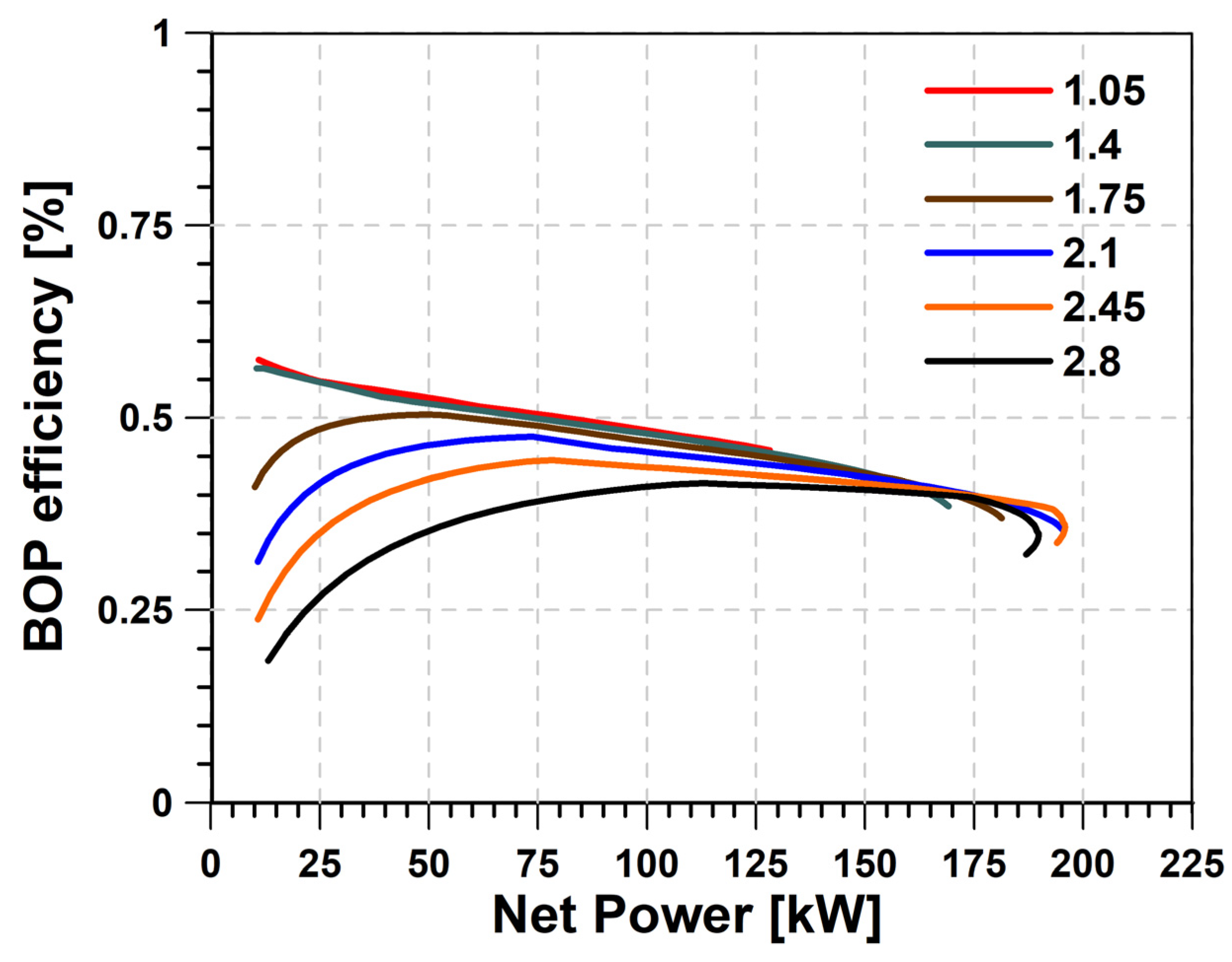
  • Evaluate the effect of the compressor operating conditions (pressure ratio and efficiency) on the compressor power consumption and balance-of-plant efficiency;
  • Quantify the implications of altitude on the maximum achievable power and energy balance;
  • Discuss the relationship between the compressor map and the altitude impact.

2. Materials and Methods

In this section, the main aspects of the methodology followed during the simulations will be detailed. First, the fuel cell balance-of-plant model will be described, including the validation of the physical model used to simulate the stack response as a function of the cathode working pressure. Then, the characteristics and working map of the Roots compressor technology under investigation will be presented. Finally, the test matrix, including altitude variations, will be summarized.

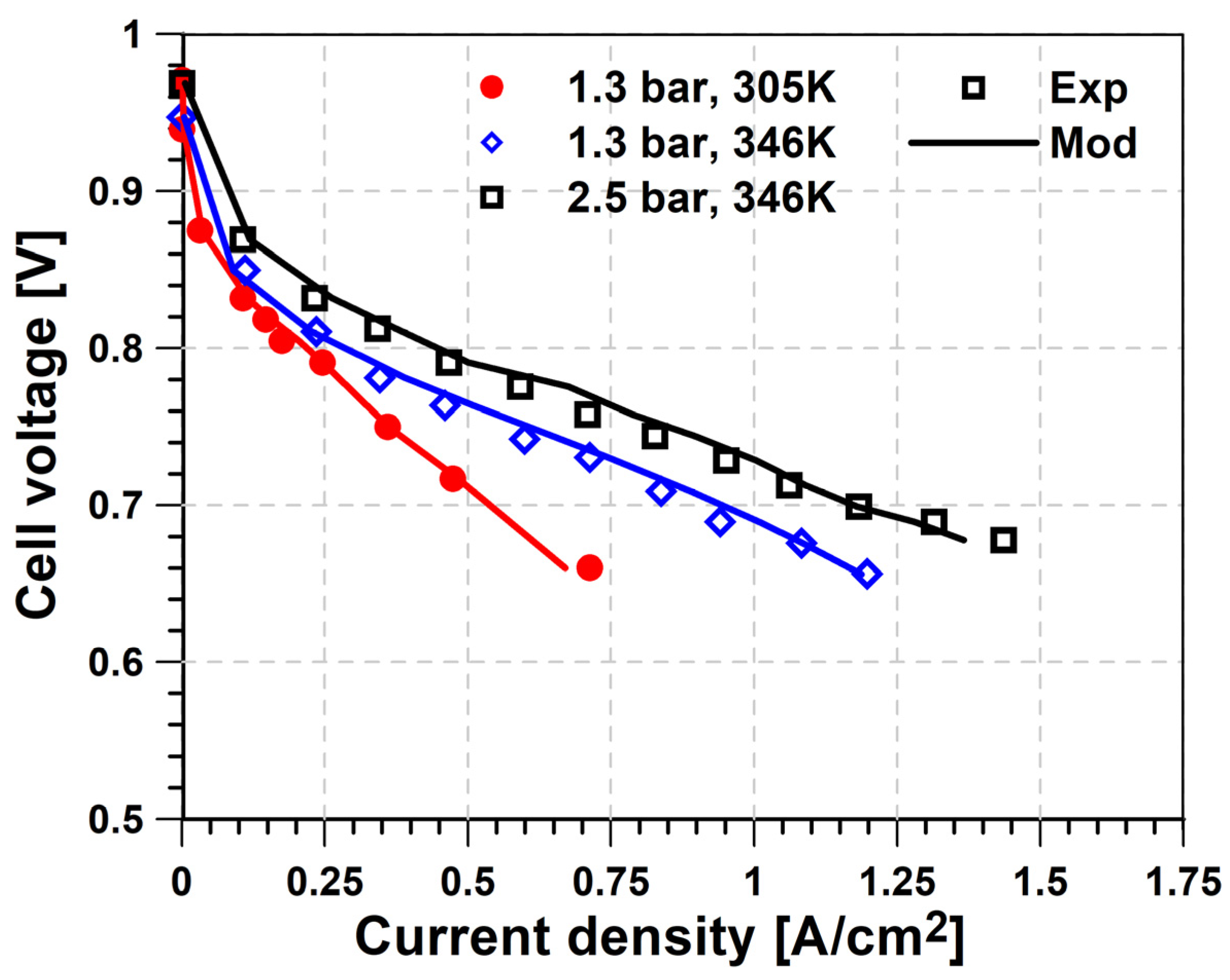
2.1. Balance-of-Plant Model

The current work explores the altitude effects on compressor and fuel cell performance for a heavy-duty vehicle. For this purpose, the balance-of-plant proposed sketch in Figure 1 is modeled using the MATLAB Simscape platform v24.1. On the anode side, the hydrogen from the fuel tank goes through a controlled valve that is used to set the operational pressure at the fuel cell inlet pin,a and afterwards to a heat exchanger to control the temperature Tin,a, particularly during the warm-up phase. After this heat exchanger, the flow coming from the fuel tank is mixed with the hydrogen excess flow recirculated from the anode exhaust by means of a recirculation pump (P). Finally, a membrane humidifier is used to set the final humidity content of the anode stream. In the cathode side, the first element in the line is an air filter, which is necessary to ensure that no impurities arrive at the cathode gas channels and is characterized by a 2% pressure drop at the maximum mass flow conditions. Afterwards, an electrically driven compressor is used to control the mass flow and pressure of the air arriving at the fuel cell (pin,c), where a second heat exchanger is used to control the inlet temperature Tin,c. Finally, a second membrane humidifier sets the humidity level of the cathode gas stream, using water recuperated from the cathode exhaust as the water source. It has to be considered that, in addition to these elements, a real system would also include two additional elements that are not considered in the current simulations. First, a thermal management system is used to maintain the PEMFC stack at the optimal working temperature (around 70 °C) once the system’s warm-up phase is completed. Second, a hydrogen purge circuit derives the hydrogen from the recirculation line to the cathode exhaust when the hydrogen purity reaches a certain minimum value due to nitrogen crossover across the stack. However, in the current work, these systems are not considered since they have no direct relation with the system performance in altitude conditions, which is the main scope of the activity.
One of the key elements in this model, together with the electrical compressor (which will be described in the next subsection), is the fuel cell stack itself. Given the nature of the study, it is critical that the selected submodel for the fuel cell stack provides physical sensitivity to the working pressure in the anode and cathode, which has a direct impact on both activation and mass transfer losses. In the current work, the open-source model developed by Vetter et al. [45] is selected. This model has been developed using experimental data from the literature [46,47] including different temperature and pressure conditions, up to a maximum pressure of 2.5 bar. For this purpose, the model was calibrated using data from a single polarization curve at 1.3 bar and 346 K, with the rest of the available data being used for model validation. Figure 2 shows the comparison between experimental and simulated polarization curves for three of the conditions extracted from previous studies. As can be seen, the model is well capable of reproducing the fuel cell performance in the whole current density range, not only for the curve used for the calibration, but also when inducing variations in pressure and temperature conditions. This points out that the physical model is capable of capturing pressure and temperature effects, a critical aspect for the evaluation of different altitude conditions proposed in the current study.
Once the fuel cell electrochemical response is validated at the cell level, its operation is scaled up to be representative of a PEMFC-based powertrain system in a heavy-duty vehicle [48]. Particularly, a total of 1000 cells with an active area of 280 cm2 each are considered in order to provide a maximum fuel cell power of 225 kW. Table 1 presents this information together with the most important physical and chemical parameters obtained during the fuel cell model calibration process.

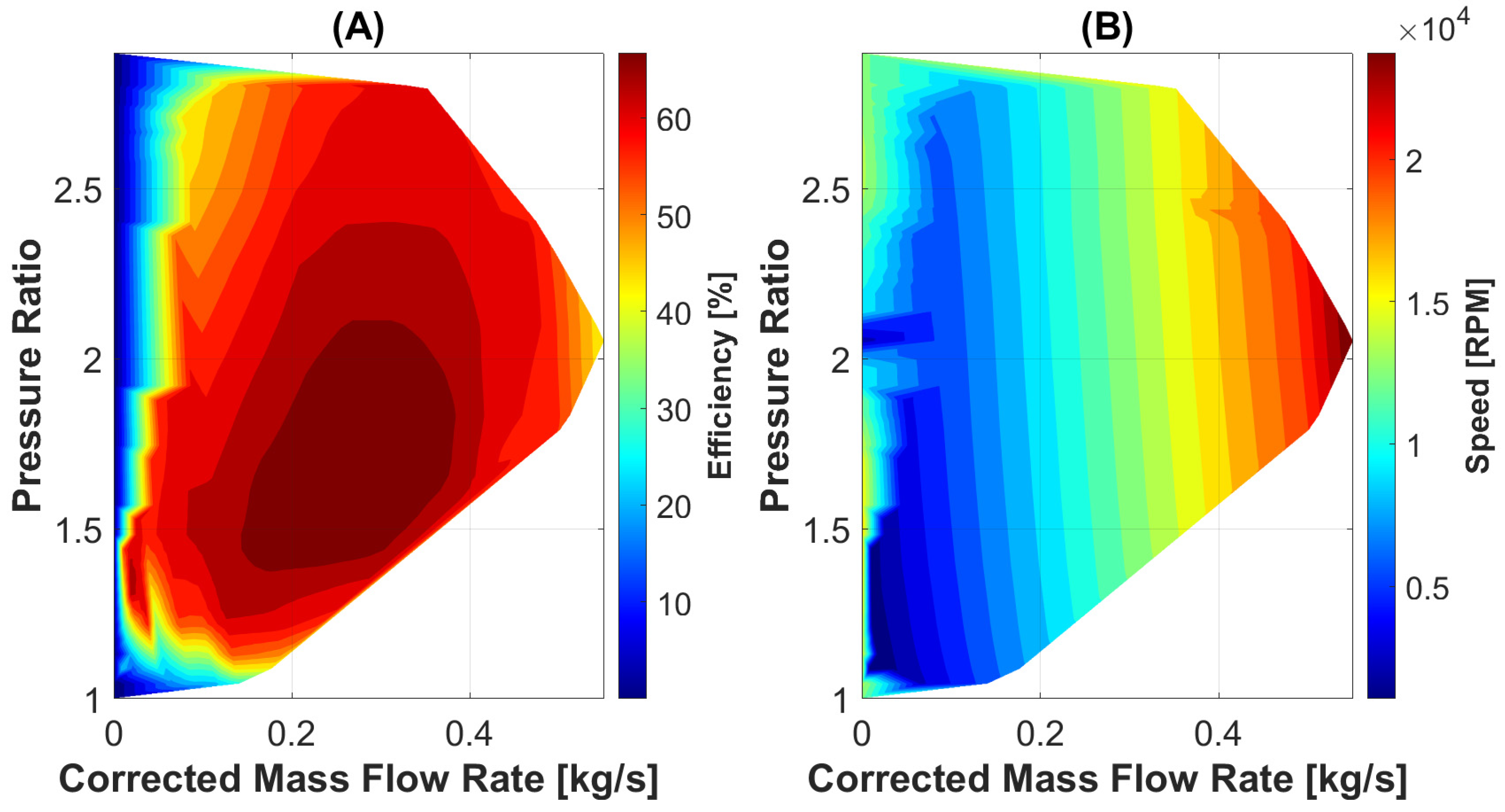
2.2. Compressor Selection and Modeling

As previously introduced, the fuel cell can be supercharged by either radial or Roots compressors. In general, a radial compressor map exhibits pressure ratio curves that reach higher values with decreasing corrected flow at a constant corrected speed. However, this increasing trend disappears when approaching the surge conditions, which are associated with low-flow-velocity environments and high-pressure-ratio conditions, inducing the appearance of backflows. These backflows induce an instability into the flow that first induces a drop in efficiency and eventually the appearance of severe vibrations and mechanical damage, limiting their boosting capability for a given mass flow value. Instead, since Roots compressors are volumetric machines with no direct contact between low-pressure and high-pressure flow areas, surge is much less prone to appear, and the maximum pressure ratio is mainly limited by the maximum temperature reached after compression. Therefore, a wider range of pressure ratios is possible for a given mass flow value, which is controlled by the rotational speed. Also, the efficiency (although it has a lower peak) is less sensitive to the flow rate compared to radial compressors. In the context of altitude operation, being less impacted by surge limitations can be a significant advantage due to the capability to compensate for the low ambient pressure by a higher-pressure-ratio operation, making it possible to maintain more similar conditions inside the fuel cell stack with a limited impact on efficiency and power consumption.
Figure 3 summarizes the characteristic maps of the roots compressor used for the current study in terms of isentropic efficiency (A) and compressor corrected speed (B) as a function of corrected mass flow and pressure ratio, which are provided by the compressor manufacturer. As can be seen, in this kind of compressor technology, the speed mainly controls the air mass flow provided, since the constant speed lines are practically vertical. Instead, at a given compressor speed, there is a wide variation in the pressure ratio, with a maximum value around 2.8 achieved up to a corrected mass flow of 0.35 kg/s (corresponding to ~15,000 rpm), from which the maximum achievable pressure ratio starts going down. Finally, it can also be noted that the peak isentropic efficiency reaches 70%, achieved in a wide area ranging from 0.15 to 0.35 kg/s and from 1.4 to 2.1 for the pressure ratio. From that point, the main efficiency deterioration is produced when the corrected mass flow reduces below 0.05 kg/s.

2.3. Simulation Conditions

Throughout the simulations, the following conditions were maintained:
  • Ambient temperature and pressure conditions are calculated as a function of altitude according to the international standard atmosphere, in a range between sea level (0 km) and 5 km.
  • The air filter is assumed to produce a maximum pressure drop of 2% for the highest operational air mass flow (0.3 kg/s). For lower air mass flows, a linear decay of this pressure drop is assumed.
  • The compressor reduced speed is controlled to achieve the target air mass flow for a constant oxygen excess ratio of 2.
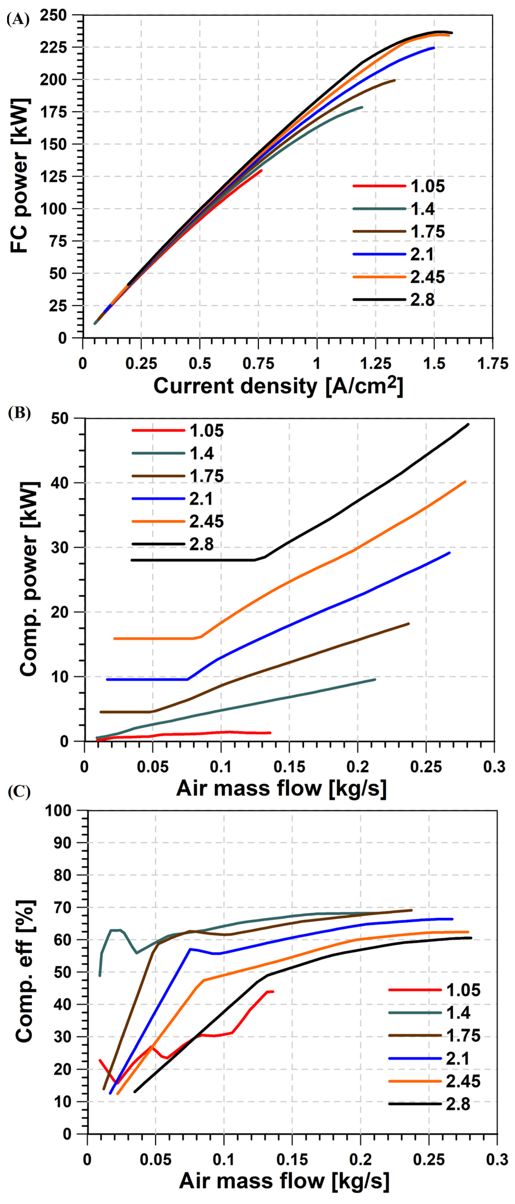
  • The compressor electrical power is adjusted to control its pressure ratio, in a range between 1.05 and 2.8, with a step size of 0.025. The inlet pressure at the fuel cell is assumed to be equal to the compressor outlet pressure for both cathode and anode streams.
  • The temperature of cathode and anode gas streams, as well as the internal fuel cell stack temperature, is set at 73 °C in order to reach the maximum proton conductivity of the membrane.
  • Relative humidity at both cathode and anode gas streams is set at 70%.
  • The hydrogen excess ratio defined at the anode inlet is set at 1.5, with the hydrogen excess being used to calculate power consumption from the recirculation pump.
  • The voltage in the fuel cell stack is limited to a minimum value of 0.6 V/cell in order to operate in the range covered during the validation phase and ensure that the stack does not reach oxygen-limited operation that could eventually lead to its degradation in real conditions.

3. Results

In this section, the main results from the simulations are presented and discussed. The analysis is divided into two parts: first, a detailed evaluation of the balance-of-plant operation and stack–compressor matching is performed at sea-level conditions; later, the impact of the altitude is evaluated for a net power range between 20 and 200 kW (or the maximum achievable value).

3.1. Sea-Level Analysis

Figure 4 shows the information about the fuel cell stack and compressor operation as a function of the pressure ratio at sea level. For this purpose, six levels of pressure ratios (between 1.05 and 2.8, in steps of 0.35) are depicted. Figure 4A shows the evolution of the power produced by the fuel cell stack against the current density (for different pressure levels). At low current densities, it can be seen that the impact of the pressure ratio is relatively small, despite higher pressures at the fuel cell stack always being positive for the fuel cell performance alone. As the current density increases, the effect of the operational pressure is more evident both in terms of the power produced and the range of current density, which reaches a maximum value of 1.6 A/cm2 for the last two pressure ratio cases. Additionally, it can be seen that for these two values, the peak power is actually produced at a slightly lower current density (~1.6 A/cm2), beyond which mass transport losses ramp up, producing a decrease in the electrical power despite the increase in the current. Figure 4B provides the counter figure in terms of compressor power consumption as a function of air mass flow. At low values of air mass flow (proportional to the fuel cell current), the compressor power is practically constant due to the fact that the increase in air mass flow is also compensated for by the continuous increase in compressor efficiency, as depicted in Figure 4C. This effect is clear as the pressure ratio on the compressor increases. At lower pressure ratio values (1.05 and 1.4), the efficiency lines show some fluctuations. This behavior is linked to the severe gradient of the efficiency map in the low-pressure-ratio and low-mass-flow areas, where the efficiency can vary from nearly 0 to 40% in a very narrow mass flow window. Therefore, small variations in the controlled rotational speed in the model can provide relatively high variations in the calculated compressor speed, which are also appreciable in the compressor power results. Once efficiency becomes more stable, compressor power consumption shows an almost linear evolution, which was dominated by the air mass flow variation. It can also be seen that the sweet spot for the compressor operation appears for pressure ratios between 1.4 and 1.75, with a peak efficiency near 70%, as already discussed when introducing the compressor map in Figure 3.
Figure 5 shows the evolution of the balance-of-plant efficiency as a function of the produced net power, which can be seen as the net balance of the aforementioned stack and compressor terms, since the recirculation pump contribution is independent of the pressure ratio selected. In general, the results show that the best efficiency is achieved when using the minimum possible pressure ratio for a given produced net power, due to the significant impact of the compressor consumption on the overall energy balance. However, as the net power demand increases, the best efficiency is found for higher pressure ratios until reaching the pr = 2.45 condition. Afterwards, further increases in the pressure do not significantly affect the fuel cell stack but translate into a higher compressor consumption, damaging the balance-of-plant efficiency.

3.2. Altitude Impact

Figure 6 analyzes the system-level performance as a function of the altitude level. Figure 6A shows the optimal pressure ratio for each altitude as a function of the balance-of-plant net power. Until approximately 100 kW, it can be seen that the optimal pressure ratio is approximately constant, with very little variation in terms of the altitude condition as well. From that point, the optimal pressure ratio increases rapidly when increasing the net power demand, which occurs more aggressively as the altitude increases, in order to compensate for the lower environmental pressure. For the most demanding conditions, the compressor can take up to 18% of the total electrical power produced by the fuel cell (Figure 6B). Looking at the extension of the data in the x-axis, it is noticeable that the maximum power also deteriorates with the altitude, with a maximum value of 135 kW (vs. the nominal 200 kW, a 32.5% deterioration) for the highest altitude of 5 km. Finally, Figure 6C provides the information on the balance-of-plant efficiency, where a deterioration between 3 and 7% can be observed when increasing the altitude at constant net power demand. This deterioration is more severe as the system approaches the rated power condition. It has to be noted that the balance-of-plant efficiency not only includes the effect of the compressor operation, but also two other power consumptions coming from the coolant and hydrogen recirculation pumps. However, these two contributions are nearly independent of the altitude since the hydrogen excess ratio and operational temperature are kept equal for all the simulations performed. Additionally, the pumps are simulated with a fixed efficiency. Instead, the altitude does have a direct impact on the compressor corrected mass flow, pressure ratio, and efficiency that drives the differences observed.
Figure 7 analyzes, in further detail, the operation of the compressor in terms of the pressure ratio (Figure 7A) and efficiency (Figure 7B) evolutions against the corrected mass flow. As can be seen, the reduction in the ambient pressure as a function of the altitude tends to increase the corrected mass flow values, whose maximum moves from around 0.25 kg/s at sea-level conditions to 0.35 kg/s in the most extreme conditions. However, thanks to the characteristics of the roots compressor selected for this study, these conditions still fall into the high-efficiency region of the compressor map, allowing for the maintenance of efficiencies between 60 and 70% throughout the majority of the operating range, even at 5 km altitude. This result confirms the suitability of this compressor technology to minimize the negative impact of altitude on the working range and efficiency of fuel cell-powered vehicles compared to other boosting systems available. However, it has to be noted that for the highest altitude of 5 km, the highest working point is limited to a corrected mass flow of 0.3 kg/s and a pressure ratio of 1.8, which is well inside the compressor map. Therefore, the net power is not limited by the extension of the compressor map itself, but by the fact that after this point, the compressor efficiency starts deteriorating again. Thus, the expected increase in the fuel cell stack power induced by the higher pressure and air mass flow is also overcome by the higher compressor power consumption coming from the lower efficiency operation.
Finally, Figure 8 shows the information about the fuel cell stack operating conditions as a function of altitude. Figure 8A depicts the actual pressure achieved in the cathode inlet stream. There is a clear decreasing trend in the working pressure with the altitude in the low-to-mid net power conditions. On the contrary, once the net power exceeds 135 kW, the optimal balance-of-plant operation is found for nearly identical levels of pressure in the cathode regardless of the working altitude. This is related to the fact that it is in these conditions where the pressure has the highest impact on the fuel cell stack performance, as can also be observed in Figure 8B. This, together with the relatively low variability of the compressor efficiency once the corrected mass flow exceeds 0.15 kg/s, makes the system optimization swing towards the sweet spot of the fuel cell stack.

4. Conclusions

In the current paper, an investigation of the altitude effects on the operation of a supercharged heavy-duty fuel cell powerplant equipped with a roots compressor is performed. For this purpose, the complete balance-of-plant model is developed in the Simscape platform. For the fuel cell stack, a one-dimensional physical and chemical model extracted from the literature is calibrated against experimental data at different temperatures and pressures at the single-cell polarization curve level. Then, the number of cells and effective areas are scaled up to provide a maximum net power of 200 kW, which is representative of the requirements of a heavy-duty vehicle. The roots compressor, characterized by a maximum pressure ratio of 2.9 and a maximum corrected flow of 0.55 kg/s, is calculated using information from the efficiency and corrected speed maps. The model is completed by including an air filter, which is characterized with a pressure drop of up to 2% for the maximum mass flow conditions, the anode recirculation system, membrane humidifiers for both anode and cathode streams, and a simplified thermal management system aimed at maintaining a constant temperature of 73 °C, where the maximum proton conductivity is found. The model is explored in an altitude range between sea level and 5 km, optimizing the compressor and fuel cell stack working points to achieve the highest balance-of-plant efficiency for a net power range between 10 and 200 kW (or the maximum achievable value at a given altitude). With this methodology, the following conclusions can be made:
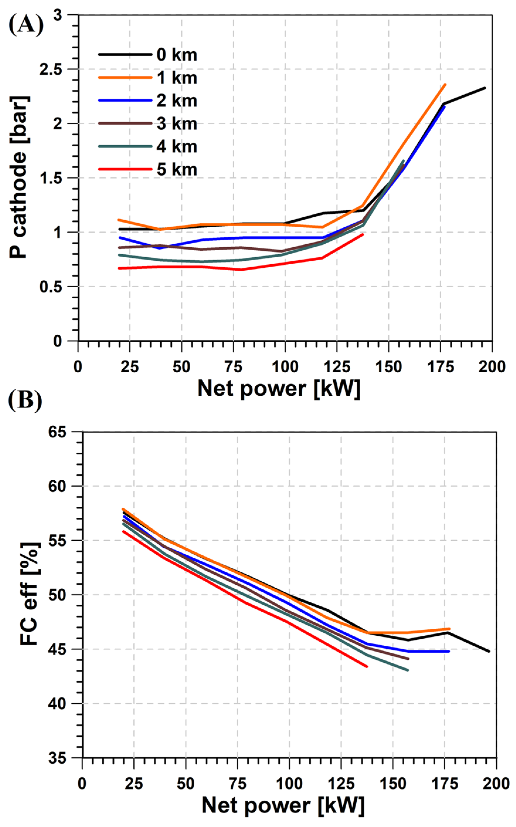
  • The pressure in the fuel cell stack helps to extend the current density operating range and therefore increase the achievable fuel cell power. However, the sensitivity to pressure starts reducing when the pressure exceeds 2 bar, where the minimum differences are achieved from 2.45 bar on.
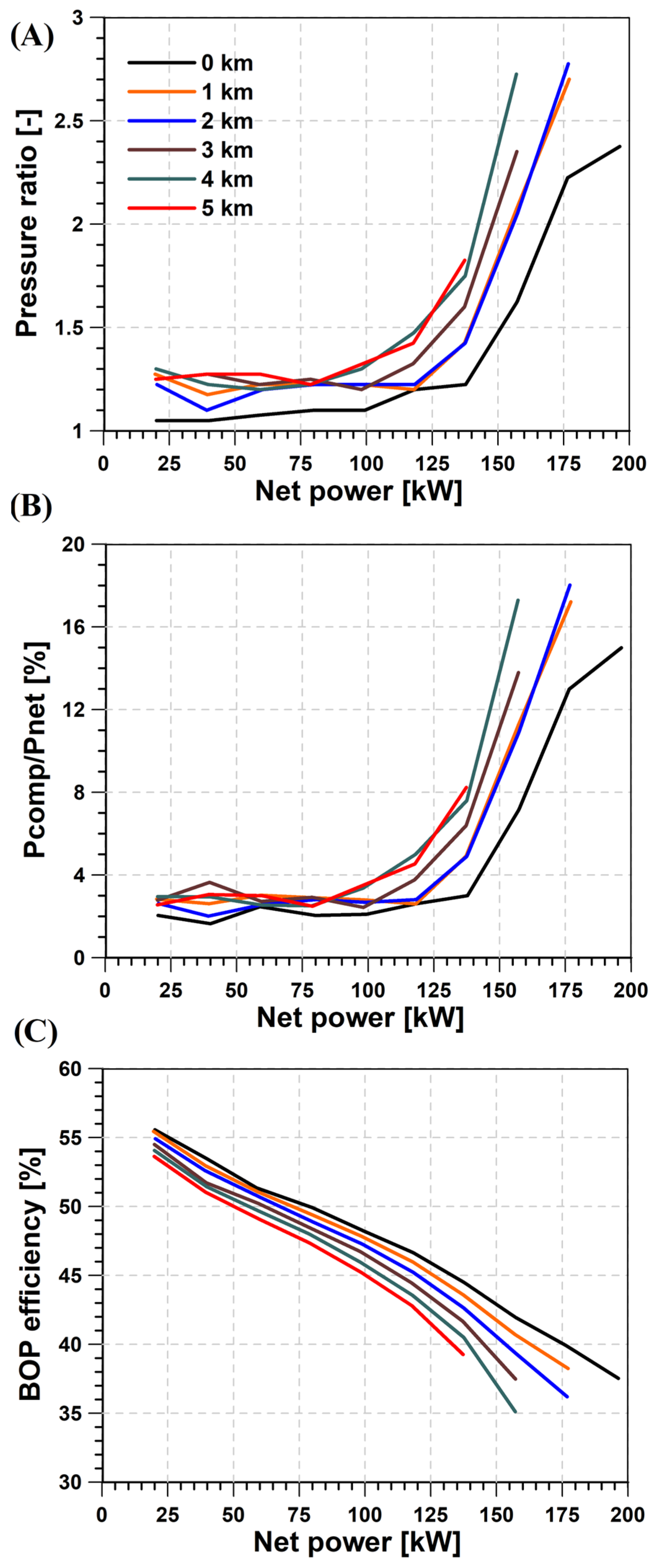
  • At sea-level operations, a minimum compressor power consumption is seen at low-to-mid fuel cell power (i.e., air mass flow) operations, which are dominated by the isentropic efficiency evolution. This minimum power increases nearly exponentially with the pressure ratio.
  • At mid-to-high-power conditions, the Roots compressor efficiency is nearly constant and close to the highest efficiency, and the compressor power consumption is dominated by the air mass flow.
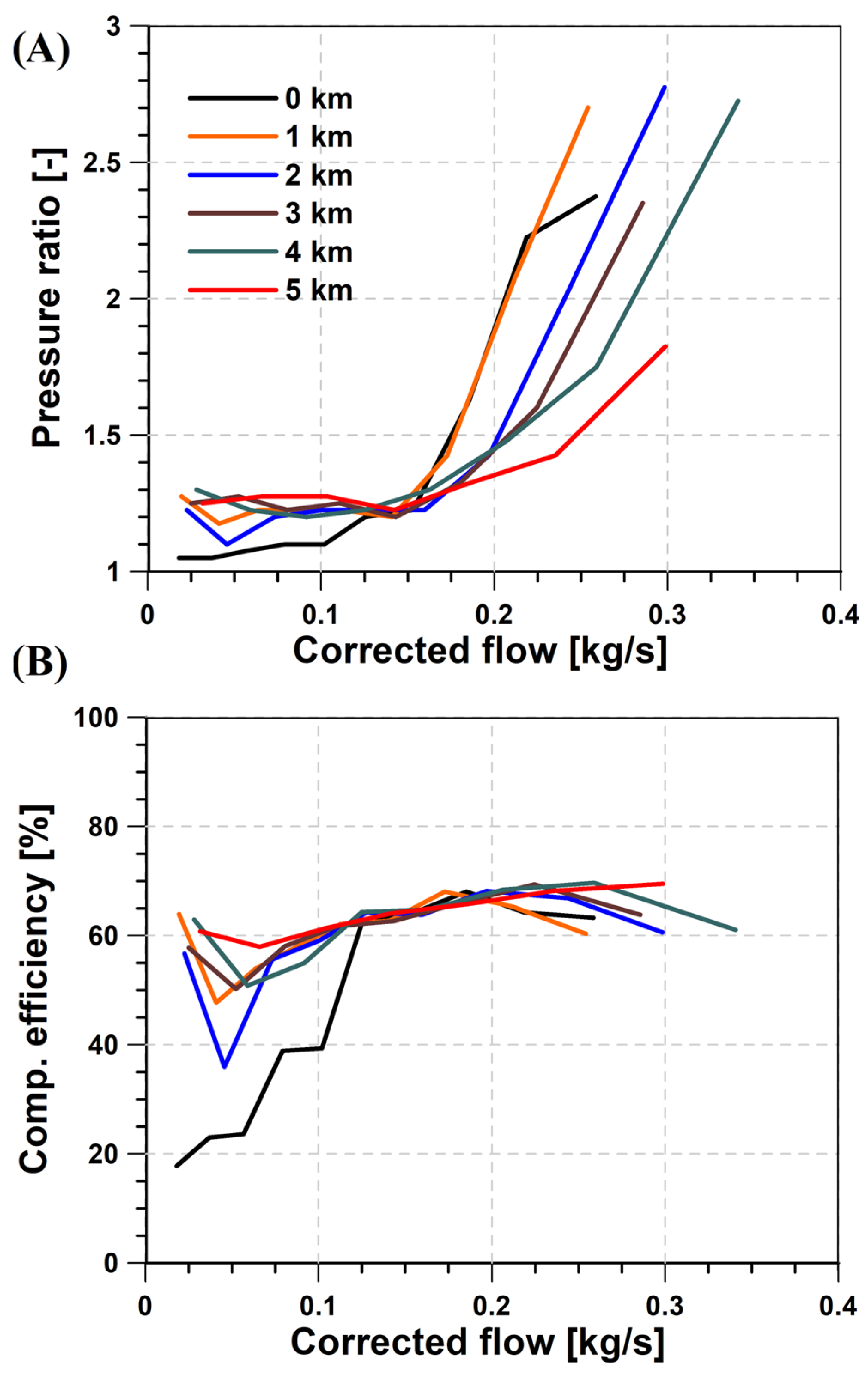
  • As altitude increases, the maximum corrected air mass flow tends to increase as a consequence of the lower ambient pressure. However, thanks to the characteristics of the Roots compressor, it operates with minimal changes in efficiency (between 60 and 70%) for a wide range of altitude and mass flow conditions.
  • For the highest altitude and power operating conditions, the combined increase in corrected mass flow and pressure ratio makes the compressor leave the best efficiency area, consequently increasing the power consumption and limiting the maximum balance-of-plant performance. Particularly, the peak net power produced is lowered from 200 kW at sea level to 135 kW at a 5 km altitude, which represents a 32.5% deterioration. Additionally, the balance-of-plant efficiency is also impaired, reaching up to a 7% reduction.
  • At mid-to-low net power operations, the best efficiency values are reached for nearly constant (and low) pressure ratios, with a slight increase as a function of the altitude. Consequently, the fuel cell stack operating pressure is reduced, inducing a penalty in efficiency of up to 3%.

Author Contributions

Conceptualization, P.P. and J.d.l.M.; methodology, P.P.; software, E.J.S. and I.S.; validation, J.d.l.M. and E.J.S.; formal analysis, P.P.; investigation, J.d.l.M.; resources, P.P.; data curation, I.S.; writing—original draft preparation, J.d.l.M. and I.S.; writing—review and editing, P.P. and E.J.S.; visualization, E.J.S.; supervision, P.P.; project administration, J.d.l.M.; funding acquisition, J.d.l.M. All authors have read and agreed to the published version of the manuscript.

Funding

This research was partially funded by the Spanish Ministry of Science and Innovation with funding from the European Union NextGenerationEU (PRTR-C17.11) and by the Generalitat Valenciana as project INNOMAT-H2 (MFA/2022/041).

Institutional Review Board Statement

Not applicable.

Informed Consent Statement

Not applicable.

Data Availability Statement

The dataset is available upon request from the authors.

Conflicts of Interest

The authors declare no conflicts of interest. The funders had no role in the design of the study; in the collection, analyses, or interpretation of the data; in the writing of the manuscript; or in the decision to publish the results.

Abbreviations

The following abbreviations are used in this manuscript:
BOPBalance of plant
CLCatalyst layer
FCFuel cell
FCVFuel cell vehicle
GDLGas diffusion layer
MElectric motor
OEROxygen excess ratio
PHydrogen recirculation pump
PEMProton-exchange membrane
PEMFCProton-exchange membrane fuel cell
pin,aAnode inlet pressure
pin,cCathode inlet pressure
prPressure ratio
Tin,aAnode inlet temperature
Tin,cCathode inlet temperature
UAVUncrewed air vehicle

References

  1. Summary for Policymakers—Global Warming of 1.5 °C n.d. Available online: https://www.ipcc.ch/sr15/chapter/spm/ (accessed on 23 October 2024).
  2. Rissman, J.; Bataille, C.; Masanet, E.; Aden, N.; Morrow, W.R.; Zhou, N.; Elliott, N.; Dell, R.; Heeren, N.; Huckestein, B.; et al. Technologies and policies to decarbonize global industry: Review and assessment of mitigation drivers through 2070. Appl. Energy 2020, 266, 114848. [Google Scholar] [CrossRef]
  3. Vision 2050: A Strategy to Decarbonize the Global Transport Sector by Mid-Century. International Council on Clean Transportation n.d. Available online: https://theicct.org/publication/vision-2050-a-strategy-to-decarbonize-the-global-transport-sector-by-mid-century/ (accessed on 23 October 2024).
  4. Samsun, R.C.; Rex, M.; Antoni, L.; Stolten, D. Deployment of Fuel Cell Vehicles and Hydrogen Refueling Station Infrastructure: A Global Overview and Perspectives. Energies 2022, 15, 4975. [Google Scholar] [CrossRef]
  5. Anand, C.; Chandraja, B.; Nithiya, P.; Akshaya, M.; Tamizhdurai, P.; Shoba, G.; Subramani, A.; Kumaran, R.; Yadav, K.K.; Gacem, A.; et al. Green hydrogen for a sustainable future: A review of production methods, innovations, and applications. Int. J. Hydrogen Energy 2025, 111, 319–341. [Google Scholar] [CrossRef]
  6. Sá, M.H. Electrochemical Devices to Power a Sustainable Energy Transition—An Overview of Green Hydrogen Contribution. Appl. Sci. 2024, 14, 2168. [Google Scholar] [CrossRef]
  7. Candelaresi, D.; Valente, A.; Iribarren, D.; Dufour, J.; Spazzafumo, G. Comparative life cycle assessment of hydrogen-fuelled passenger cars. Int. J. Hydrogen Energy 2021, 46, 35961–35973. [Google Scholar] [CrossRef]
  8. Desantes, J.M.; Molina, S.; Novella, R.; López-Juárez, M. Comparative global warming impact and NOX emissions of conventional and hydrogen automotive propulsion systems. Energy Convers. Manag. 2020, 221, 113137. [Google Scholar] [CrossRef]
  9. Usai, L.; Hung, C.R.; Vásquez, F.; Windsheimer, M.; Burheim, O.S.; Stromman, A.H. Life cycle assessment of fuel cell systems for light duty vehicles, current state-of-the-art and future impacts. J. Clean. Prod. 2021, 280, 125086. [Google Scholar] [CrossRef]
  10. Mei, J.; Meng, X.; Tang, X.; Li, H.; Hasanien, H.; Alharbi, M.; Dong, Z.; Shen, J.; Sun, C.; Fan, F.; et al. An Accurate Parameter Estimation Method of the Voltage Model for Proton Exchange Membrane Fuel Cells. Energies 2024, 17, 2917. [Google Scholar] [CrossRef]
  11. Boudghene Stambouli, A.; Traversa, E. Fuel cells, an alternative to standard sources of energy. Renew. Sustain. Energy Rev. 2002, 6, 295–304. [Google Scholar] [CrossRef]
  12. Bermúdez, V.; Serrano, J.R.; Piqueras, P.; Diesel, B. Fuel consumption and aftertreatment thermal management synergy in compression ignition engines at variable altitude and ambient temperature. Int. J. Engine Res. 2022, 23, 1954–1966. [Google Scholar] [CrossRef]
  13. Mancino, A.N.; Menale, C.; Vellucci, F.; Pasquali, M.; Bubbico, R. PEM Fuel Cell Applications in Road Transport. Energies 2023, 16, 6129. [Google Scholar] [CrossRef]
  14. Wee, J.-H. Applications of proton exchange membrane fuel cell systems. Renew. Sustain. Energy Rev. 2007, 11, 1720–1738. [Google Scholar] [CrossRef]
  15. Loo, K.H.; Wong, K.H.; Tan, S.C.; Lai, Y.M.; Tse, C.K. Characterization of the dynamic response of proton exchange membrane fuel cells—A numerical study. Int. J. Hydrogen Energy 2010, 35, 11861–11877. [Google Scholar] [CrossRef]
  16. Wang, Z.; Liu, Z.; Fan, L.; Du, Q.; Jiao, K. Application progress of small-scale proton exchange membrane fuel cell. Energy Rev. 2023, 2, 100017. [Google Scholar] [CrossRef]
  17. Majlan, E.H.; Rohendi, D.; Daud, W.R.W.; Husaini, T.; Haque, M.A. Electrode for proton exchange membrane fuel cells: A review. Renew. Sustain. Energy Rev. 2018, 89, 117–134. [Google Scholar] [CrossRef]
  18. Wang, H.; Yin, Y.; Hui, X.; Bail, J.; Qu, Z. Prediction of effective diffusivity of porous media using deep learning method based on sample structure information self-amplification. Energy AI 2020, 2, 100035. [Google Scholar] [CrossRef]
  19. Tellez-Cruz, M.M.; Escorihuela, J.; Solorza-Feria, O.; Compañ, V. Proton Exchange Membrane Fuel Cells (PEMFCs): Advances and Challenges. Polymers 2021, 13, 3064. [Google Scholar] [CrossRef]
  20. Liu, Z.; Liu, Z.; Jiao, K.; Yang, Z.; Zhou, X.; Du, Q. Numerical investigation of ejector transient characteristics for a 130-kW PEMFC system. Int. J. Energy Res. 2020, 44, 3697–3710. [Google Scholar] [CrossRef]
  21. Piqueras, P.; De La Morena, J.; Sanchis, E.J.; Lalangui-Gallegos, J.A. Potential of Proton-Exchange Membrane Fuel-Cell System with On-Board O2-Enriched Air Generation. Appl. Sci. 2024, 14, 836. [Google Scholar] [CrossRef]
  22. Wang, R.; Li, K.; Cao, J.; Yang, H.; Tang, H. Air supply subsystem efficiency optimization for fuel cell power system with layered control method. Renew. Energy 2024, 235, 121328. [Google Scholar] [CrossRef]
  23. Hoeflinger, J.; Hofmann, P. Air mass flow and pressure optimisation of a PEM fuel cell range extender system. Int. J. Hydrogen Energy 2020, 45, 29246–29258. [Google Scholar] [CrossRef]
  24. Kulikovsky, A.A. The effect of stoichiometric ratio λ on the performance of a polymer electrolyte fuel cell. Electrochim. Acta 2004, 49, 617–625. [Google Scholar] [CrossRef]
  25. Liu, J.; Gao, Y.; Su, X.; Wack, M.; Wu, L. Disturbance-Observer-Based Control for Air Management of PEM Fuel Cell Systems via Sliding Mode Technique. IEEE Trans. Control Syst. Technol. 2019, 27, 1129–1138. [Google Scholar] [CrossRef]
  26. Kuang, J.; Lv, J.; Hao, W.; Lin, X.; Zhao, D.; Matraji, I.; Muhl, P.; Liu, J. Oxygen excess ratio control of PEM fuel cell systems with prescribed regulation time. ISA Trans. 2023, 142, 683–692. [Google Scholar] [CrossRef] [PubMed]
  27. Yu, Q.; Wang, J.; Huang, W.; Li, X.; Liu, Z.; Dong, H. Sliding Mode Integral Separation PID Control for Hydrogen Fuel Cell Systems. Appl. Sci. 2024, 14, 7650. [Google Scholar] [CrossRef]
  28. Wu, Y.; Bao, H.; Fu, J.; Wang, X.; Liu, J. Review of recent developments in fuel cell centrifugal air compressor: Comprehensive performance and testing techniques. Int. J. Hydrogen Energy 2023, 48, 32039–32055. [Google Scholar] [CrossRef]
  29. Blunier, B.; Miraoui, A. Air management in PEM fuel cells: State-of-the-art and prospectives. In Proceedings of the 2007 International Aegean Conference on Electrical Machines and Power Electronics, Bodrum, Turkey, 10–12 September 2007; pp. 245–254. [Google Scholar] [CrossRef]
  30. Liu, M.; Wang, C.; Han, Y.; Xing, Z. Potential Evaluation of Twin-Screw Air Expanders with Dual-Lead Rotors Used in PEMFC Systems. Appl. Sci. 2024, 14, 9983. [Google Scholar] [CrossRef]
  31. Zhao, D.; Xu, L.; Huangfu, Y.; Dou, M.; Liu, J. Semi-physical modeling and control of a centrifugal compressor for the air feeding of a PEM fuel cell. Energy Convers. Manag. 2017, 154, 380–386. [Google Scholar] [CrossRef]
  32. Wang, S.; Jin, D.; Zhang, Y.; Wang, K.; Gui, X. A forward-curved blade centrifugal compressor for anode recirculation in proton exchange membrane fuel cells. Int. J. Hydrogen Energy 2024, 53, 736–748. [Google Scholar] [CrossRef]
  33. Ahsan, N.; Al Rashid, A.; Zaidi, A.A.; Imran, R.; Abdul Qadir, S. Performance analysis of hydrogen fuel cell with two-stage turbo compressor for automotive applications. Energy Rep. 2021, 7, 2635–2646. [Google Scholar] [CrossRef]
  34. Hou, J.; Yang, M.; Ke, C.; Zhang, J. Control logics and strategies for air supply in PEM fuel cell engines. Appl. Energy 2020, 269, 115059. [Google Scholar] [CrossRef]
  35. Liu, M.; Wang, C.; Li, Y.; Li, Y.; Liu, L.; Xing, Z. Experimental Investigation on the Effect of Water Cooling on a Dry Twin-Screw Air Compressor for Proton Exchange Membrane Fuel Cell. Appl. Sci. 2024, 14, 2537. [Google Scholar] [CrossRef]
  36. Özel, M.A.; Sümer, O. Controlling and Experimental Validation of an Air Compressor System with Energy Efficient Novel Pressurized Air Cabin for Open-Cathode PEM Fuel Cell. Appl. Sci. 2025, 15, 2158. [Google Scholar] [CrossRef]
  37. Gao, J.; Zhou, S.; Lu, Y.; Shen, W. Simulation of a Novel Integrated Multi-Stack Fuel Cell System Based on a Double-Layer Multi-Objective Optimal Allocation Approach. Appl. Sci. 2024, 14, 2961. [Google Scholar] [CrossRef]
  38. Hordé, T.; Achard, P.; Metkemeijer, R. PEMFC application for aviation: Experimental and numerical study of sensitivity to altitude. Int. J. Hydrogen Energy 2012, 37, 10818–10829. [Google Scholar] [CrossRef]
  39. Spiegel, R.J.; Gilchrist, T.; House, D.E. Fuel cell bus operation at high altitude. Proc. Inst. Mech. Eng. Part A J. Power Energy 1999, 213, 57–68. [Google Scholar] [CrossRef]
  40. Haraldsson, K.; Alvfors, P. Effects of ambient conditions on fuel cell vehicle performance. J. Power Sources 2005, 145, 298–306. [Google Scholar] [CrossRef]
  41. Zhao, D.; Xia, L.; Dang, H.; Wu, Z.; Li, H. Design and control of air supply system for PEMFC UAV based on dynamic decoupling strategy. Energy Convers. Manag. 2022, 253, 115159. [Google Scholar] [CrossRef]
  42. Pratt, J.; Brouwer, J.; Samuelsen, G. Experimental Performance of an Air-Breathing PEM Fuel Cell at High Altitude Conditions. In Proceedings of the 43rd AIAA Aerospace Sciences Meeting and Exhibit, American Institute of Aeronautics and Astronautics, Reno, NV, USA, 10–13 January 2005. [Google Scholar] [CrossRef]
  43. Lapeña-Rey, N.; Blanco, J.A.; Ferreyra, E.; Lemus, J.L.; Pereira, S.; Serrot, E. A fuel cell powered unmanned aerial vehicle for low altitude surveillance missions. Int. J. Hydrogen Energy 2017, 42, 6926–6940. [Google Scholar] [CrossRef]
  44. Plazas, A.; Naghshtabrizi, P.; Payri, R.; Martí-Aldaraví, P.; Gómez-Vilanova, A. Fuel Cell Humidity Control via Water Injection and its Influence on Root Compressor Performance. In Proceedings of the THIESEL 2024 Conference on Thermo- and Fluid Dynamics of Clean Propulsion Powerplants, Valencia, Spain, 10–13 September 2024; Valencia Polytechnic University: Valencia, Spain, 2024; ISBN 978-84-1396-275-7. [Google Scholar] [CrossRef]
  45. Vetter, R.; Schumacher, J.O. Free open reference implementation of a two-phase PEM fuel cell model. Comput. Ohysics Commun. 2019, 234, 223–234. [Google Scholar] [CrossRef]
  46. Corbo, P.; Migliardini, F.; Veneri, O. Experimental analysis of a 20 kWe PEM fuel cell system in dynamic conditions representative of automotive applications. Energy Convers. Manag. 2008, 49, 2688–2697. [Google Scholar] [CrossRef]
  47. Corbo, P.; Migliardini, F.; Veneri, O. Experimental analysis and management issues of a hydrogen fuel cell system for stationary and mobile application. Energy Convers. Manag. 2007, 48, 2365–2374. [Google Scholar] [CrossRef]
  48. Novella, R.; De La Morena, J.; López-Juárez, M.; Nidaguila, I. Effect of differential control and sizing on multi-FCS architectures for heavy-duty fuel cell vehicles. Energy Convers. Manag. 2023, 293, 117498. [Google Scholar] [CrossRef]
Figure 1. Sketch of balance-of-plant model.
Applsci 15 05513 g001
Figure 2. Validation of the fuel cell stack model.
Applsci 15 05513 g002
Figure 3. Compressor performance maps: (A) isentropic efficiency map and (B) compressor speed map.
Applsci 15 05513 g003
Figure 4. Fuel cell stack and compressor operation as a function of the pressure ratio at sea-level conditions: (A) fuel cell stack power, (B) compressor power, and (C) compressor efficiency.
Applsci 15 05513 g004
Figure 5. Balance-of-plant efficiency as a function of the pressure ratio at sea-level conditions.
Applsci 15 05513 g005
Figure 6. Balance-of-plant efficiency and compressor as a function of the altitude: (A) optimal pressure ratio; (B) ratio of compressor power and net BOP power; and (C) BOP efficiency.
Applsci 15 05513 g006
Figure 7. Compressor working point as a function of altitude: (A) pressure ratio vs. corrected mass flow; (B) efficiency vs. corrected mass flow.
Applsci 15 05513 g007
Figure 8. Fuel cell stack operation as a function of altitude: (A) cathode inlet pressure; (B) fuel cell stack efficiency.
Applsci 15 05513 g008
Table 1. Fuel cell parameters.
ParameterValue (Units)
Number of cells in stack1000
Cell area280 cm2
Membrane thickness125 µm
Gas diffusion layer (GDL) thickness160 µm
Catalytic layer (CL) thickness10 µm
Symmetry factor0.5
Density of dry membrane2000 kg/m3
Equivalent weight of dry membrane1.1 kg/mol
Disclaimer/Publisher’s Note: The statements, opinions and data contained in all publications are solely those of the individual author(s) and contributor(s) and not of MDPI and/or the editor(s). MDPI and/or the editor(s) disclaim responsibility for any injury to people or property resulting from any ideas, methods, instructions or products referred to in the content.

