1. Introduction
Eastern Türkiye, influenced by a protracted history characterized by significant seismic activity and evolving architectural practices, has once more faced the catastrophic impacts of earthquakes during the Kahramanmaraş incidents on 6 February 2023. These seismic events, registering magnitudes of Mw 7.7 (Pazarcik) and Mw 7.6 (Elbistan), inflicted extensive damage across numerous provinces and highlighted the vulnerabilities inherent in the current building inventory. Compounding the situation, there was a seismic event of magnitude Mw 6.4 occurred in Hatay just two weeks after, exacerbating the destruction of buildings that had already been compromised due to the preceding tremors [
1].
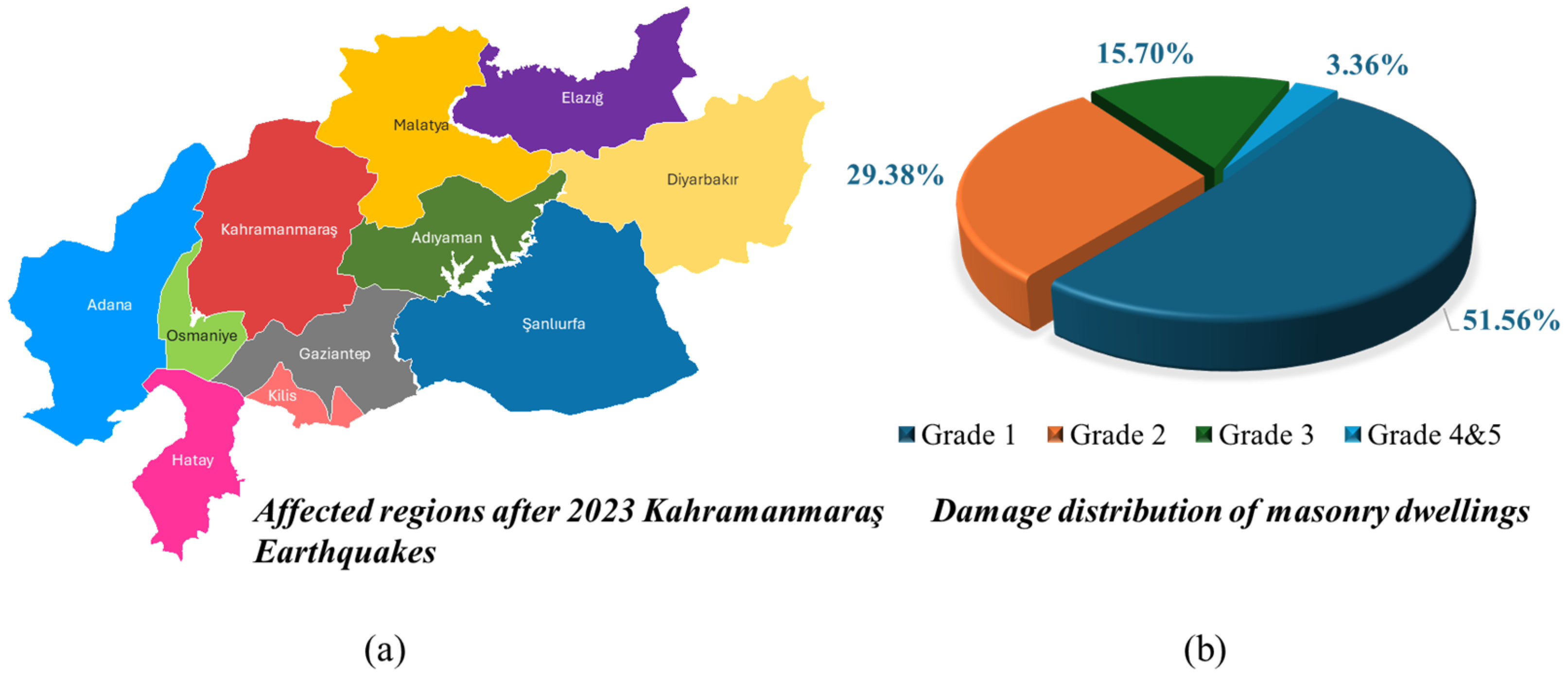
The earthquake series affected eleven provinces, including Kahramanmaraş, Hatay, Gaziantep, Malatya, Diyarbakır, Kilis, Şanlıurfa, Adıyaman, Osmaniye, Adana, and Elazığ. A quick territorial damage assessment in rural villages was conducted by the author. These evaluations’ approach depended on the European Macroseismic Scale (EMS-98) [
2]. Damage to masonry structures is classified by the EMS-98 [
2] into five successive stages. Usually confined to superficial hairline fractures in plaster with minimal structural consequences, Grade 1 denotes little to minor damage. Grade 2 is substantial damage without affecting structural integrity; it includes noticeable wall fractures or mild plaster separation. Grade 3 shows significant-to-severe deterioration, with broad fractures, local masonry disintegration, and early indications of structural instability. Reflecting major structural damage, Grade 4 corresponds to extremely severe damage, with partial failure or collapse of considerable wall portions. Grade 5 indicates whole or near-total building devastation, including the collapse of load-bearing components and total structural failure.
Figure 1 shows the geographic range of seismic effect across 11 provinces during the 2023 Kahramanmaraş earthquake series and offers the related distribution of damage in masonry dwellings.
As shown in
Figure 1, field evaluations conducted by the author classified damage in 2568 masonry buildings using EMS-98 [
2]. The results indicate that approximately 51.56% of the masonry buildings surveyed had Grade 4 or 5 damage using the EMS-98 [
2] classification, indicating extremely significant damage or destruction. About 29.38% matched Grade 3, which indicated significant structural degradation with indications of instability. While only 3.36% of the structures were classified as Grade 1, indicating minor damage, another 15.70% fell under Grade 2, indicating considerable cracking without complete structural weakening. This figure draws attention to the great vulnerability of the area masonry building stock, much of which was built without following current seismic design guidelines. The concentration of damage in Grades 3–5 supports the conclusion that occupant-driven expansions, poor mortar quality, and the lack of ring beams were the major causes of general structural collapse in the impacted area.
A pivotal aspect of the eastern Anatolian framework is the longstanding inclination towards unreinforced masonry (URM). Within both rural and peri-urban settings, residential structures are predominantly constructed from stone, earthen materials, or low-fired clay bricks, frequently with negligible involvement from professional engineers. Over time, these structures are modified by the inhabitants themselves, resulting in irregular shapes, the elimination of essential walls, or unfinished upper levels that further compromise lateral load resistance. As highlighted by Işık et al. [
3], modifications made by occupants in earthen masonry (adobe) homes may utilize local soils with deficient tensile strength, substantially increasing the likelihood of corner detachment, diagonal fractures, and out-of-plane collapses. Previous research, including that of Tomazevic [
4] and Sumerente et al. [
5], corroborates the idea that earthen constructions globally exhibit analogous susceptibilities, even in the presence of moderate seismic activity, unless they are enhanced through improved mortar strength, the inclusion of ring beams, or external reinforcement. The 2023 Kahramanmaraş earthquakes represent merely the latest instance of a recurring phenomenon wherein occupant modifications and insufficient design scrutiny yield catastrophic failure mechanisms.
A comprehensive analysis of the global seismic behavior of masonry buildings deepens our comprehension of the challenges faced in selected rural provinces of eastern Türkiye. Field evaluations in this research were mostly done in areas like Adıyaman, Malatya, Gaziantep, Hatay, and Kahramanmaraş, where URM dwellings are common and often altered by residents without engineering supervision. In this context, the term “occupant expansions” refers to structural additions made by homeowners, like extra rooms, kitchen wings, or even second stories, that are typically built without permits, design drawings, or any input from engineers. These additions often disrupt the balance and continuity of the original structure, making them more prone to failure during seismic events. Similar weaknesses have been recorded elsewhere. For example, in Italy, notable seismic events, such as those in Emilia-Romagna [
6,
7,
8] and L’Aquila [
9], demonstrated that traditional masonry, encompassing both stone and brick, exhibits vulnerability to out-of-plane failures, corner fractures, and partial collapses in the absence of ring beams or ties. Penna et al. [
8] established sophisticated retrofitting techniques, including external tie rods or near-surface mounted reinforcements, to significantly enhance the durability of older masonry constructs. However, alterations driven by occupants, particularly in rural Italian villages, frequently occur without regulation, resulting in a phenomenon analogous to occupant expansions in Türkiye.
In southeastern and eastern Anatolia, occupant expansions present a microcosm of these global concerns. The expansions are typically constructed for extra living space, storage, or extended family members, yet rarely incorporate ring beams or uniform mortar. According to occupant interviews after the 2023 Kahramanmaraş quakes [
10,
11], expansions often follow local craft tradition, relying on friction-based mortar and interior walls improvised from leftover bricks or stone rubble. While the Specification for Masonry Structures (TMS 602) [
12] or Turkish Building Earthquake Code (TBEC 2018) [
13] would ordinarily require continuous horizontal ties and compliance with specified shear capacities, occupant expansions proceed unobserved by official authorities, leading to partial or total collapses under significant lateral shaking. These expansions also hamper any prospect of large-scale hazard mapping or microzonation if the dwellings deviate from the assumptions of code-based geometry. One of the significant characteristics of occupant expansions is their capacity to convert a stable, albeit outdated, single-story masonry structure into one exhibiting abrupt vertical or horizontal discrepancies. When expansions are executed outwardly, new access points are chiseled into load-bearing walls, resulting in openings that compromise in-plane shear strength and may induce diagonal fractures. Conversely, occupant expansions may introduce a second level that is inadequately anchored to the foundational walls, establishing a precariously top-heavy configuration, particularly on earthen mortar.
Around the world, many earthquake-prone countries face a common issue: residents gradually expand their homes without formal engineering input. A clear example of this occurred during the 2015 Gorkha earthquake in Nepal, where many URM houses collapsed not because of original construction flaws, but due to extra stories and rooftop rooms added over time, often without any seismic reinforcement. Similar cases have been reported in Mexico and Iran, where post-earthquake surveys revealed that informal structural additions were a key factor in building failures. These kinds of modifications are not just cosmetic upgrades or extra rooms. They are significant structural changes that typically fall outside the scope of building codes and engineering oversight. Because of that, they often go unaccounted for in design assumptions and risk models, quietly increasing vulnerability until a major event exposes the weakness [
14,
15,
16,
17,
18,
19].
Apart from changes brought on by occupants, the usage of mortar in conventional masonry construction creates a major structural flaw. The Turkish Academy of Sciences (TUBA) [
20] emphasizes that resident families typically blend local earth or sand, at times integrating straw for earthen blocks, or utilize unrefined riverbed aggregates for stone walls. This type of mortar demonstrates poor cohesion and limited tensile strength, exacerbating shear or corner fractures when subjected to lateral forces from seismic events. On a global scale, Tomazevic [
4] noted that the compressive strength of mortar should correspond to the compressive strength of the blocks to facilitate proper load distribution and mitigate joint sliding. Nonetheless, the modifications made by occupants seldom replicate the mortar specifications (if any were present) of the original construction. Rather, resident families often opt for less expensive, friction-based bonding agents that, upon enduring recurrent vibrations, deteriorate, particularly in proximity to expansions or corners.
A further complicating factor is ring beam omission or partial usage. The TMS 602 [
12] suggests ring beams or confining elements at critical horizontal intervals to tie walls together and prevent out-of-plane disintegration. Similarly, the TBEC (2018) [
13] mandates horizontal ties or belts in larger masonry walls to forestall vertical separation. Occupant expansions, however, seldom see ring beams installed at the new roof–wall interface. Instead, occupant families typically lay wooden joists or, in some cases, steel beams directly on top of unreinforced walls, ignoring the ring beam concept. Observations from the 2023 Kahramanmaraş events confirm that occupant expansions lacking ring beams frequently collapsed outward, generating large debris fields that hampered rescue efforts [
20]. Similar patterns were observed worldwide in older masonry expansions without ring beams, including post-quake reconnaissance in the 2009 L’Aquila quake, the 2011 Christchurch (New Zealand) event, the 2017 Puebla–Morelos (Mexico) quake, and 2017 Kermanshah (Iran) quake [
9,
21,
22,
23,
24]. In each case, occupant expansions or partial additions aggravated the dwellings’ vulnerability.
In conclusion, occupant expansions, low-grade mortar, and absent ring beams collectively represent the trifecta behind older masonry collapses in eastern Türkiye, particularly in adobe or stone-based building types. Substantial occupant expansions in rural communities produce structural anomalies that code-based design does not anticipate, while occupant acceptance remains elusive if solutions appear expensive or culturally incongruent. Meanwhile, major seismic events highlight these deficiencies with stark clarity. If occupant expansions remain invisible to policy or occupant expansions are neglected in code-based vulnerability frameworks, older masonry in eastern Türkiye will remain perpetually at risk, yielding tragic outcomes whenever large quakes strike.
Moreover, post-earthquake onsite investigations significantly enhance the development of more seismically resilient structures for future seismic events. The identification of weaknesses in compromised buildings is crucial for the design and construction of more suitable structures. Thus, it is reasonable to assert that the understanding of the seismic performance of structures has been augmented due to prior field studies. This study conducts a detailed analysis of the recorded in situ damage observed in masonry buildings. The primary aim is to identify patterns of structural vulnerabilities that are consistently present, evaluate the shortcomings of existing seismic regulations, and facilitate the advancement of construction methodologies that are both resilient and tailored to the specific contexts of Türkiye’s masonry building sector. These results are especially important for nations where the condition of the current masonry building stock is equally lacking as they provide transferable knowledge on seismic behavior.
The paper’s structure is set out as follows. To provide background for the seismicity of eastern Türkiye and its consequences for ground motion exposure,
Section 2 offers a short tectonic review. Emphasizing the effects of occupant-driven expansions and inadequate construction techniques,
Section 3 provides a thorough categorization of deterioration processes seen in masonry structures. With particular emphasis on ring beam criteria, wall slenderness limitations, mortar standards, and the official handling of illegal extensions,
Section 4 offers a historical and technical analysis of the Turkish seismic code. This development lets the reader follow the connection between reported harm and legal loopholes. The study ends with a summary of results and focused suggestions for better seismic risk control and structural resilience in masonry housing.
3. Observed Damage Mechanisms in Eastern Türkiye’s Masonry Buildings
Masonry has historically been the primary building method in parts of eastern Türkiye, due to the accessibility of local resources like stone and adobe, as well as enduring vernacular customs [
38]. These construction techniques often use basic mortar mixtures and little or nonexistent reinforcing, and they depend on empirical guidelines for sizing walls and roofs [
4]. Although these traditions have cultural importance, they often lack designed seismic details, making them vulnerable to moderate-to-high ground shaking. The global kinds of masonry include URM, confined masonry (CM), reinforced masonry (RM), and autoclaved aerated concrete (RAAC). The URM types lack reinforcement, or the reinforcing percentage is far below the levels mandated by earthquake regulations. The prevalent material types for URM are bricks, hollow concrete blocks, hollow clay tile units (HCT), stone, and adobe. In CM, the structural system consists of horizontal and vertical reinforced concrete confining components; in RM, vertical and horizontal reinforcing bars are integrated into the walls.
The quality of stone masonry is influenced by quarrying techniques, bonding configurations, and mortar durability. Certain villages use random rubble construction, while others choose to more precisely cut stone blocks to enhance interlocking. Adobe building is notably widespread, particularly in areas with an abundance of clay-rich soil. Notwithstanding adobe’s thermal advantages, its seismic performance is compromised by brittle behavior, limited tensile strength, and quick cohesion loss under cyclic stress.
The mid-20th century marked a period of partial modernization characterized by the growing accessibility of cement, steel, and industrially produced bricks. This evolution facilitated the integration of concrete lintels, ring beams, or partial reinforcement in crucial areas of the construction (e.g., corners, openings). Although these modifications contributed to alleviating specific failure mechanisms, their application was often inconsistent. In numerous cases, retrofitting was executed informally, lacking proper design calculations or adherence to building codes [
39]. As a result, the resulting hybrid systems frequently display irregular stiffness distributions, compromised mortar layers, and unpredictable overall behavior under seismic forces.
Today, masonry construction in eastern Türkiye exists in a transitional space between vernacular and engineered approaches. However, enforcement remains a challenge in remote areas, where local masons may not be fully conversant with the latest guidelines [
40]. This gap between regulation and practice leaves a significant portion of the building stock at heightened risk of seismic damage.
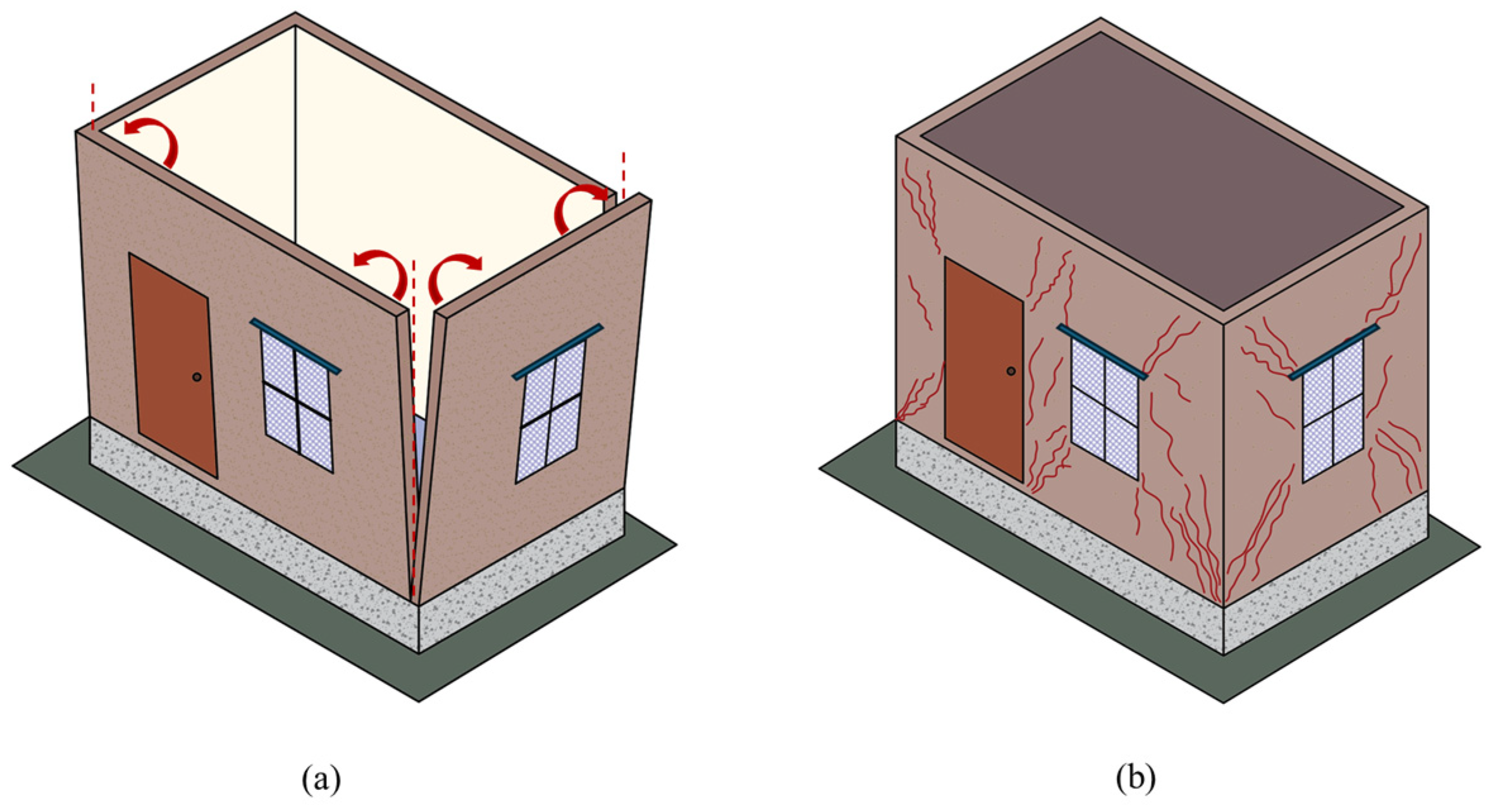
Field investigations indicated that, among masonry kinds, URM structures are mostly favored in eastern rural Türkiye. Consequently, the identified damage to masonry structures may be classified as resulting from either out-of-plane or in-plane behavior, as seen in
Figure 4. The former may be designated as the primary damage mode, resulting from seismic forces perpendicular to the wall, while the latter may be termed the secondary damage mode, arising from in-plane forces. If the walls of a structure are inadequately linked at floor levels due to out-of-plane behavior, they will split at the corners and intersections, resulting in instability and potential partial or whole collapse.
Tomazevic [
4] noted that out-of-plane behavior is less essential for seismic resistance than in-plane behavior due to the homogeneous distribution of walls in both orthogonal directions, the geometric requirements for shear walls, and the connections between walls and floors. In-plane damage arises from in-plane behavior, when severe in-plane bending or shearing leads to failure [
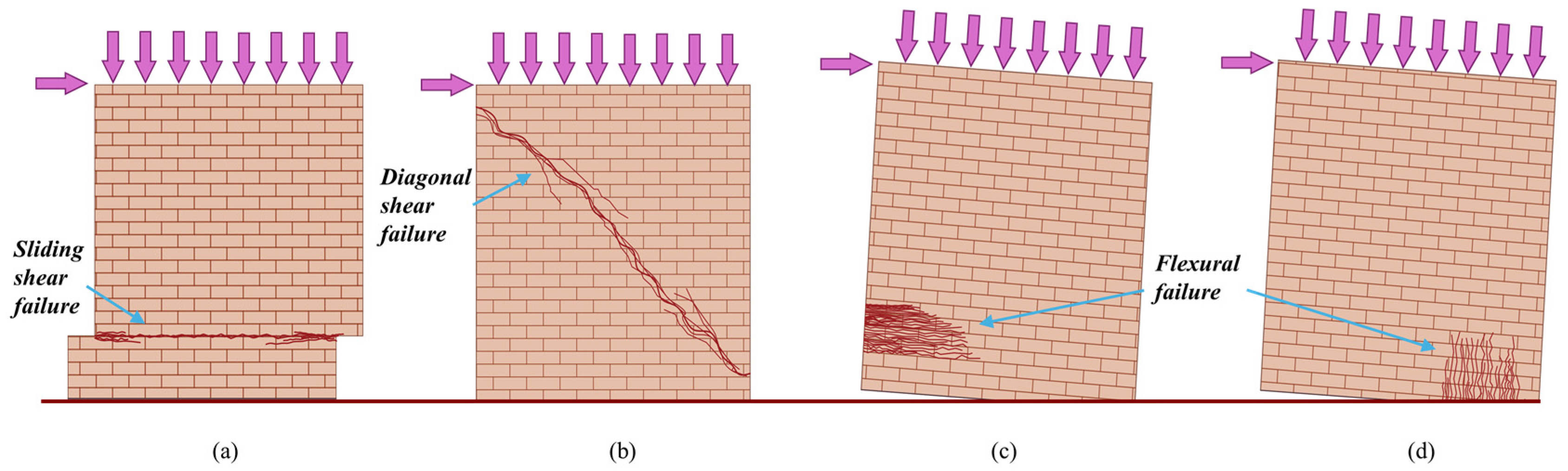
41]. Masonry wall in-plane damage may be categorized into three main types: sliding shear, diagonal shear, and flexural failure. Often, rocking and toe crushing are also seen as secondary types of flexural reaction.
Figure 5 shows common depictions of these in-plane breakdown types. Shown in
Figure 5a, sliding shear usually forms when seismic stress surpasses the frictional resistance of a weak masonry wall, hence generating horizontal displacement at the mortar joints. When lateral pressures exceed the wall’s shear strength, diagonal shear, as seen in
Figure 5b, shows itself as noticeable cracking along a diagonal path, usually starting at the corners. Exceeding the tensile capacity of the wall ends may cause this failure pattern to spread through the mortar joints and develop into a more serious state, hence generating flexural cracking as shown in
Figure 5c. Often resulting in gradual instability or total collapse, rocking behavior, shown in
Figure 5d, occurs when the wall pivots under imbalanced overturning forces. The publications of Oyguc and Oyguc [
41] and Parisi and Augent [
42] should be consulted by the reader for a thorough examination of these damage mechanisms and their consequences for masonry design.
This section provides a comprehensive analysis of the damage noted in masonry structures throughout field investigations.
3.1. Damage Modes Attributable to Poor-Quality Units and Mortar
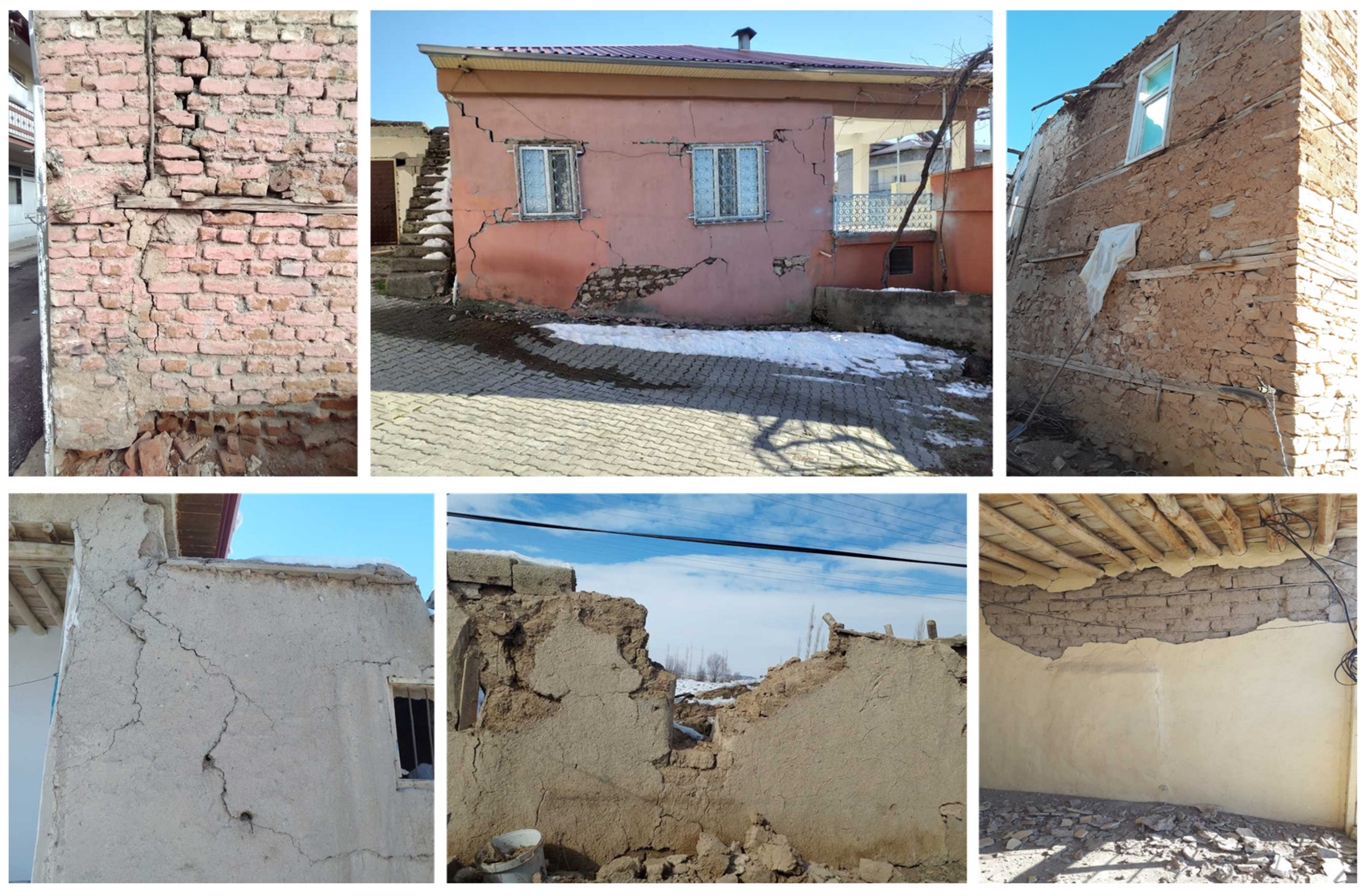
Many of the most severe problems affecting masonry construction in eastern Türkiye can be traced back to the intrinsic properties of the materials themselves and the lack of quality control in production and assembly. Low-grade mortar, substandard stone units, irregular or oversized bricks, and locally prepared adobe frequently fail to meet even minimal strength thresholds. This phenomenon was observed extensively in the aftermath of past earthquakes, when forensic investigations consistently pointed to material failure as a primary cause of extensive destruction.
3.1.1. Adobe and Partially Fired Bricks
The manufacturing procedure for adobe bricks often involves combining local soil, frequently rich in clay, with straw or other fibers to enhance tensile strength. The composite material is subsequently formed and permitted to undergo drying in ambient air for an extended period, spanning several days or weeks. This method is characterized by inconsistency and the absence of rigorous quality assessments. The ratio of straw, the specific kind of clay soil, the moisture content, and the drying conditions may significantly fluctuate across several batches, leading to bricks with variable mechanical qualities and compressive strengths often recorded below 2 MPa. Freeze–thaw cycles, moisture, and humidity exacerbate the deterioration of these materials, resulting in small fractures that enlarge under lateral seismic stresses.
Field investigators noted that complete adobe walls disintegrated during mild ground shaking, sometimes beginning with vertical fissures at inadequately bonded edges and resulting in out-of-plane toppling [
41]. Primary factors were inadequate cohesiveness at the mortar–adobe contact and the inherent brittleness of the dried blocks. In residences where proprietors attempted to mitigate deficiencies by applying multiple adobe layers or partial plastering with low-strength mortar, the issue persisted, signifying that the inherent characteristics of adobe necessitated more profound interventions to adequately meet seismic requirements.
In some regions, residents or local masons try to overcome the limits of adobe by using burnt clay bricks produced in small-scale kilns. The inconsistent heating and timing mechanisms of the kilns result in partly burnt bricks that provide only slight improvements compared to sun-dried adobe [
43]. The bricks often display partial vitrification, resulting in some strata being brittle or crumbly, while others may possess more density. These inherent irregularities are evident in color gradations, where darker areas indicate more intense firing, whereas lighter or muted regions often signify insufficient firing. In
Figure 6, examples of this type of damage have been presented.
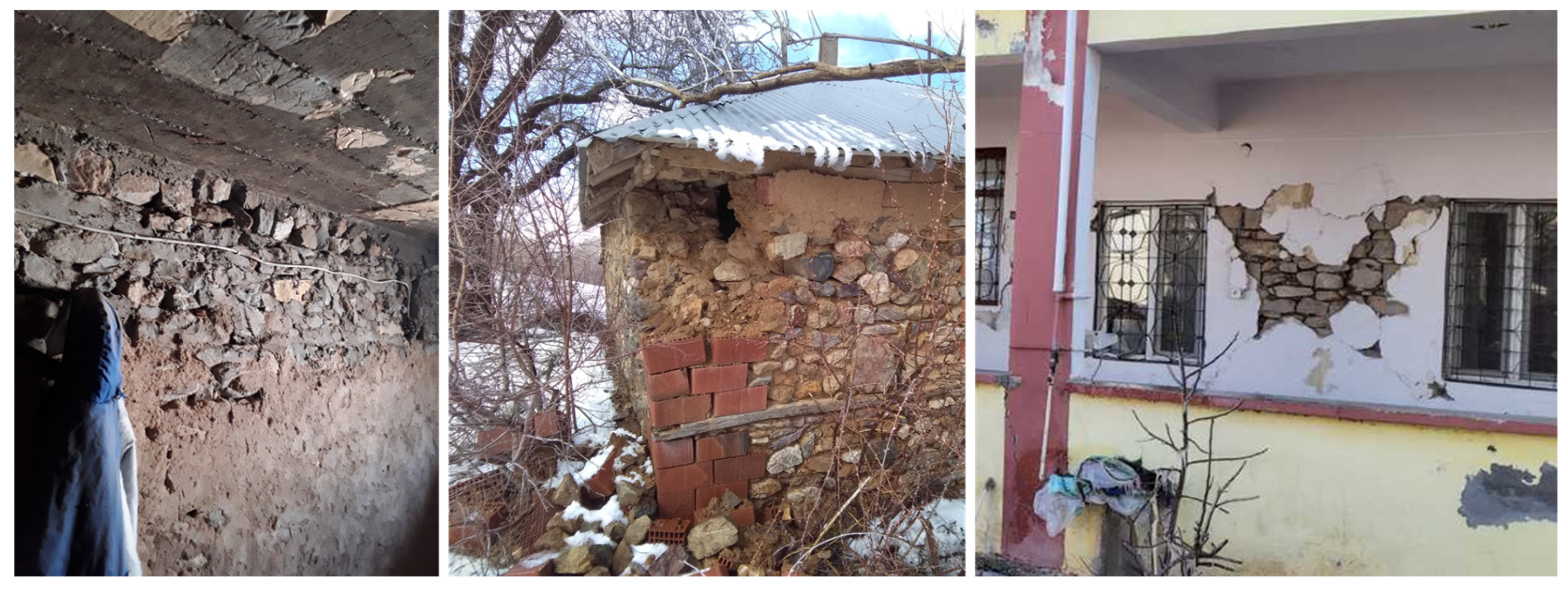
3.1.2. Stone Blocks of Variable Quality
In many regions of eastern Türkiye, stone masonry has traditionally been the predominant building method owing to the natural availability of basalt, limestone, tuff, and other sedimentary and volcanic rock resources. Although stone walls may demonstrate considerable compressive strength when properly cut, dressed, and erected, many regional constructions use irregularly shaped or inferior stone blocks that significantly undermine seismic performance [
41]. Deficiencies in stone quality, cutting techniques, and assembly processes often result in brittle, poorly bonded walls that are susceptible to various collapse mechanisms during moderate-to-intense seismic activity.
A prominent issue is that several stones are used in their “rubble” state, indicating they are sourced from local quarries or riverbeds and incorporated into walls with less or no modification. Consequently, individual blocks exhibit irregular geometry and fail to create cohesive, interconnecting surfaces. This results in substantial mortar-filled voids between stones, creating a discontinuous load path inside the wall section. Cyclic lateral stresses from seismic waves induce stress concentrations at these gaps, leading to premature mortar cracking and potential delamination of exterior stone veneers. Post-earthquake reconnaissance after the 2011 Van earthquakes and 2023 Kahramanmaraş earthquakes revealed whole wall portions removed from corners or mid-lengths, mostly due to inadequate fitting between neighboring stones.
A further issue emerges from the variety of rock types used in the same wall. Stone blocks may vary not only in form but also in geological composition; some may exhibit more brittleness, while others may have enhanced elasticity or superior strength. This heterogeneity induces inconsistent stiffness along the wall’s length and height, resulting in varying deformations under lateral stimulation. Consequently, weaker or more brittle stones may serve as “weak links” where fractures originate, ultimately propagating throughout the wall. Post-earthquake damage assessments in rural regions following the earthquakes indicated that structures composed of mixed stone types often exhibited intricate cracking patterns accompanied by partial out-of-plane failures at the junctions of stronger and weaker stone components [
44]. Field observations for this type of application are given in
Figure 7.
3.1.3. Hollow Clay Tiles and Composite Configurations
HCT modules are often used in regions seeking to partially modernize conventional masonry structures. The anticipated benefits often focus on decreased weight, enhanced insulation, and superior homogeneity in comparison to entirely sun-dried bricks or uneven stone blocks [
4]. Field observations after major earthquakes in eastern Türkiye, including the 2011 Van, 2020 Elazığ–Sivrice and 2023 Kahramanmaraş earthquakes, reveal that the advantages of HCTs are often compromised by inferior manufacture, insufficient mortar, and irregular installation. Consequently, HCT-based masonry walls may demonstrate brittleness, reduced shear capability, and a propensity for sudden failures under moderate-to-severe seismic forces.
Nonetheless, this design reduces the effective cross-sectional area that counters lateral and in-plane forces, especially when the tile webs are inadequately filled or poorly bonded with mortar. If mortar application is careless or insufficient, the tile voids may remain partly unfilled, preventing a secure integration between units. Field observations verified several occurrences in which whole HCT-based infill or partial load-bearing walls experienced out-of-plane ejection of tile segments. Minor fissures emerged in the corners of the tile webs and rapidly expanded, compromising the wall’s weight transfer system.
Local construction methods sometimes endeavor to integrate HCTs with other masonry materials, such natural stone, adobe bricks, or partly baked clay bricks, inside a singular building [
45]. This method may arise from gradual enhancements or extensions executed by homeowners, whereby the bottom level retains a stone foundation, but the subsequently added higher level is constructed using HCTs to save weight. Although these mixed-material configurations theoretically address certain mass-related challenges, they practically result in significant stiffness discontinuities and inconsistent bonding surfaces.
The diverse mechanical and thermal qualities of various masonry materials hinder their smooth integration. A stone foundation with an uneven top surface might obstruct appropriate seating for the HCTs above, resulting in substantial mortar joints susceptible to breaking. The interaction with inferior mortar exacerbates these interface zones, promoting delamination when cyclical seismic stresses induce out-of-phase displacements between the two segments. In several residences analyzed after the 2023 Kahramanmaraş earthquake, the top HCT section was noted to have largely collapsed independently of the bottom stone or adobe section, highlighting how inadequate interface quality essentially negated any composite action. Common damage models in HCTs and composite walls can be attributed as out-of-plane ejection of tile segments, diagonal shear with rapid crack propagation, and interface failure in hybrid walls. Example photos are shown in
Figure 8.
3.1.4. Poor-Quality Mortar
Mortar functions as the essential binding matrix that ensures shear and tensile continuity for masonry units [
4]. In several rural and semi-urban areas of eastern Türkiye, particularly inside the EAF zone, mortars are manufactured with little standardization or chemical regulation. Inferior-quality mortar is a primary factor contributing to the significant structural failures seen during moderate-to-severe seismic events. The following sections examine critical elements of inferior mortar quality, its conventional manufacturing techniques, and the manner in which it engenders a wide array of significant damage mechanisms under seismic stress.
The inclusion of soil-based aggregates or “clayey” sands contributes organic materials and particles that impede cohesive bonding. During the 2011 Van earthquakes, the 2020 Elazığ–Sivrice earthquake and 2023 Kahramanmaraş earthquakes, field testers identified mortar layers containing substantial aggregates of silt or clay, whereby incomplete hydration of these aggregates resulted in microvoids capable of expansion under dynamic stress [
41,
44].
It should be noted that due to logistical constraints and the emergency nature of the field deployment, no Schmidt hammer, rebound testing, or core extraction was performed. Instead, material assessments were conducted visually, with qualitative evaluations based on crack morphology, separation behavior, and unit fragmentation patterns during field inspections. Field studies indicate that the compressive strengths of local mortars can fall below 2 MPa, far lower than the minimum 5 MPa often advised in contemporary construction regulations for load-bearing masonry. Furthermore, the tension and shear capabilities are significantly inadequate, and are parameters essential for withstanding lateral stresses during seismic events. In the 2023 Kahramanmaraş earthquakes, whole masonry courses significantly lost their vertical load-bearing capability with the emergence of diagonal fractures in the mortar, resulting in the top parts of walls detaching and collapsing outward. Further, shear slip at horizontal mortar joints was consistently recorded, indicating that the mortar was insufficiently robust to convey in-plane pressures beyond modest seismic activity levels.
A detrimental interaction arises between inferior mortar and low-quality masonry components, such partly burned bricks, rubble stone, or uneven blocks. The usual limitations in mortar strength and adhesion exacerbate the underlying flaws in the pieces, resulting in monolithic action just in name. In instances when mortar is inadequate to cover substantial voids, the frictional or cohesive adhesion is negligible. Consequently, any isolated fissures in the mortar, initiated by minor lateral displacement, rapidly propagate to the adjacent units. Reconnaissance from the regional earthquakes reveals that structures constructed with random-rubble stone and inferior mortar are susceptible to out-of-plane bulging and rapid corner separations. Furthermore, in structures using HCTs, insufficient or partial mortar coverage leads to premature failure of tile webs, causing them to separate from the mortar matrix under horizontal shear forces. Typical failure modes due to poor-quality mortars can be categorized as bed-joint sliding, diagonal cracks focusing on joints, and out-of-plane wall ejection. Field observations concerning this issue are shown in
Figure 9.
3.2. Inadequate Craftsmanship in Masonry Construction
In numerous areas of eastern Türkiye, especially within the seismically active EAF zone, masonry structures are still erected in accordance with long-established traditions, frequently without the benefit of formal engineering supervision [
41]. Although these practices may foster regionally specific architectural elements, they often lead to considerable deficiencies in craftsmanship. When the foundational materials, such as bricks, stones, or mortar, are of inferior quality, the detrimental effects of inadequate craftsmanship are exacerbated, resulting in buildings that are fundamentally unprepared to endure seismic forces [
46]. Post-seismic evaluations in this region consistently highlight substandard or erratic craftsmanship as a significant contributor to the extensive and, at times, disproportionate levels of damage recorded during moderate seismic events [
44].
3.2.1. Irregular Laying of Units
A fundamental tenet in masonry engineering is the organized offsetting of joints to guarantee strong interlocking among courses. For example, the utilization of stretcher bond or running bond configurations in brick masonry minimizes the vertical alignment of joints, consequently fostering even distribution of stress in the face of shear and out-of-plane forces. Nevertheless, conventional construction practices in eastern Türkiye frequently overlook these design principles. Instead, masonry units are arranged based on immediate practicality, resulting in vertical joints being stacked directly above each other. This vertical alignment accelerates the propagation of cracks, allowing fissures to extend uninhibited from one course to its adjacent counterpart. This occurrence was commonly documented in reconnaissance assessments conducted after the earthquakes in the region, wherein entire wall sections fractured along uninterrupted vertical mortar joints.
In the context of stone masonry, the irregularity of shapes and the lack of thorough finishing necessitate that masons frequently engage in a process of “fitting” stones on-site through a method of trial-and-error. Stones that do not align properly are either forcibly wedged into place or are left with substantial interstitial voids that are subsequently filled with a thick, inferior-quality mortar. This technique, often termed random-rubble or “bag-placed” stonework, results in significant voids within the wall’s cross section [
46]. In a typical instance, blocks may only make contact at their corners, producing a fragile mortar matrix in between. In the event of an earthquake, these mortar-filled voids tend to fail prematurely, while the stone blocks may pivot or rotate, ultimately leading to either partial or complete structural failure.
Even when utilizing rectangular bricks or HCTs, it is common for constructors to overlook the necessity of half or quarter unit overlapping at corners and T-junctions. In the case of interior corners or L-junctions formed by intersecting walls, the omission of “toothing” or interlocking of bricks leads to a significant vertical seam. This seam serves as a critical point of vulnerability under lateral forces, resulting in the potential for corners to separate or fragment with minimal lateral displacement. Observations following the regional earthquakes indicated that entire corner sections were dislodged where these vertical seams extended from the foundation to the roof level. Field photos of this damage type are shown in
Figure 10.
3.2.2. Inconsistent Mortar Application
The absence of systematic regulation in rural locales results in local masons or property owners generally adhering to informal mixing proportions, often estimating sand-to-binder ratios through shovel loads as opposed to precise quantification. The addition of water is frequently executed “visually” based on the preferred consistency rather than adhering to a specific water-to-cement or water-to-lime ratio. Consequently, batches of mortar can exhibit significant variability even within a single structure, leading to a mosaic of stronger and weaker areas. For instance, a particular section of a wall may inadvertently possess a marginally more cohesive mortar if the mason temporarily maintained a reduced water content, while a neighboring section could be excessively porous and susceptible to disintegration if an overabundance of water was incorporated.
In certain communities, the aggregates themselves, frequently derived from local sandy soil, may incorporate excessive fines, silt, and even organic debris. These contaminants further diminish the mortar’s effective binding capability, obstructing the attainment of any substantial shear or tensile strength. During seismic events, such poorly proportioned mortars tend to fail abruptly through bed-joint sliding or diagonal tension, resulting in either the partial or total structural failure of walls.
Furthermore, the practice of employing “face shell bedding”, wherein mortar is exclusively applied along the periphery of HCTs or partially fired bricks, results in unfilled interior sections. This incomplete bonding significantly impedes shear transfer among units and promotes the infiltration of water, thereby intensifying freeze–thaw damage. Numerous inspections conducted following the regional earthquakes revealed that partially filled joints disintegrated into powder with minimal mechanical disturbance, exposing the transient bond established by inadequate mortar application. Observed damage due to inconsistent mortar application is shown in
Figure 11.
3.2.3. Absence of Key Structural Details
A fundamental tenet in seismic engineering is to ensure that masonry walls function integrally, with sufficient confinement and strong connections between perpendicular walls, floors, and roofs [
8,
46]. Nonetheless, in numerous areas of eastern Türkiye, conventional masonry residences overlook critical structural components such as ring beams, vertical confining elements, and dependable wall-to-floor tie systems [
41]. Consequently, the structural load pathways are inadequate, promoting the propagation of fissures and localized failures once seismic accelerations surpass moderate limits. The subsequent subsections investigate how the lack or improper implementation of these elements induces significant damage modes.
A prevalent deficiency observed in masonry structures is the absence of comprehensive ring beams at both flooring and roofing levels. These horizontal structural elements, commonly referred to as bond beams, are typically anticipated to encompass the full perimeter of the masonry framework, playing a crucial role in interlinking discrete wall sections and effectively distributing lateral forces. In the EAF zone, however, a notable proportion of masonry residences either entirely forgo the inclusion of ring beams or implement them irregularly, often with inadequate reinforcement or interruptions at the corners. This structural inadequacy results in out-of-plane instability, characterized by the outward bulging of entire wall panels under lateral forces, particularly evident near the uppermost courses. Additionally, corners are adversely affected when ring beams do not create continuous loops, as this leads to incomplete bridging between orthogonal walls and permits out-of-plane rotations to occur with minimal resistance [
46].
Vertical tie columns, which are crucial components in the confinement of masonry structures, are frequently overlooked or only superficially implemented in numerous constructions. The underlying principle of these vertical confining elements is to integrate steel reinforcement within boundary columns, thus consolidating wall segments into a cohesive entity. Regrettably, local builders often end the columns a few centimeters above the foundation or entirely omit them at the upper course, which obstructs a continuous load path from the foundation to the roof. During dynamic seismic activity, diagonal tension cracks that could potentially be mitigated by tie columns traverse uninterrupted along the full height of the wall, leading to the detachment and fall of substantial triangular segments. Observations from the 2023 Kahramanmaraş earthquakes revealed numerous residential structures with incomplete vertical ties, where the reinforcement was either insufficient or inadequately anchored to ring beams, rendering the confinement system largely ineffective.
A further widespread issue is the inadequate or entirely absent anchorage between walls and roofs, particularly for substantial earthen roofs or tile-based coverings. Rather than securely fastening the roof diaphragm to the supporting walls, regional customs frequently involve placing wooden beams or logs on the walls without any mechanical anchorage. This configuration significantly restricts the capacity of the walls to function cohesively; when seismic activity generates horizontal forces, the roof mass shifts laterally, exerting pressure on the upper sections of the walls, which are not anchored to a ring beam or vertical columns. The resulting pivoting or rotation around the mid height or corners often results in either partial or complete collapse of the wall, occasionally worsened by deteriorating mortar at the roof junction [
41].
Even when circumferential beams and vertical support columns are ostensibly incorporated, negligence regarding continuity, alignment, or adequate anchorage undermines their intended functionality [
46]. Cases of misaligned beams that bypass lintels or openings, or tension columns that do not converge with ring beams at corners, result in incomplete load transfer mechanisms; seismic forces subsequently propagate along these discontinuities, exacerbating fissures where the beams are merely positioned atop mortar layers. In certain structures, ring beams function more as partial load-bearing projections than as cohesive structural elements, highlighting the significant disparity between regulatory standards and actual practice [
44].
The immediate consequences of these absent or inadequate specifications manifest as significant damage patterns. Corners and wall edges lacking ring beams or columns are infamous for experiencing out-of-plane rotations, resulting in the detachment of wedge-shaped corner fragments. Extensive cracks also emerge along the uppermost courses when the roof’s inertial loads surpass the insufficient resistance of unrestrained walls, leading to outward failures. Substantial diagonal fractures extending from the foundation to the eaves arise in the absence of vertical ties, allowing in-plane shearing to convert a complete wall into two distinct wedges or triangular sections. Examples of observed damage caused by this deficiency are presented in
Figure 12.
3.3. Damage from Heavy Earthen Roofing
The substantial weight of earthen roofing markedly increases the seismic vulnerability of conventional masonry buildings in eastern Türkiye. This roofing method, which is primarily favored due to the plentiful availability of indigenous raw materials and advantageous thermal insulation characteristics, employs a composite layering system that generally incorporates soil, clay, organic fibrous substances such as straw, and, on occasion, stone aggregates, all of which are supported by wooden structural components like beams or timber joists. The overall mass of these layers considerably intensifies the inertial forces exerted on the underlying masonry walls during seismic events, thus aggravating structural susceptibility.
The conventional execution of these substantial roofing systems frequently neglects the imperative for robust anchorage systems to support masonry walls. Rather, there is a prevalent tendency to depend on frictional bonds or rudimentary mechanical fasteners. In the event of seismic activity, this insufficient anchorage leads to differential displacements between the roof and walls, resulting in considerable horizontal movement. As these lateral inertial forces escalate, the inadequately secured, heavy roof mass generates substantial out-of-plane bending stresses. As a result, wall segments, particularly those adjacent to the roof–wall interface, become susceptible to significant deformation, cracking, bulging, or, ultimately, structural failure because of deficient connection detailing.
Furthermore, the considerable weight of these roofs intensifies the damage patterns that have been observed, particularly at wall junctions, corners, and around apertures. An uneven distribution of loads due to the inconsistent application or varying thicknesses of roofing materials results in specific areas of heightened stress concentration, which promotes the development of diagonal shear cracks and progressive structural degradation.
Field evaluations undertaken subsequent to seismic occurrences consistently underscored significant destruction directly associated with the utilization of heavy earthen roofing techniques. Numerous cases of either total or partial failure of roofing systems were documented, which critically compromised the structural integrity of masonry walls and markedly increased the volume of debris produced. The expansive debris fields not only hindered emergency response and rescue endeavors but also substantially elevated dangers to both occupants and first responders. Furthermore, the absorption of moisture by earthen roofs enhances their mass and accelerates degradation processes, particularly during seasonal freeze–thaw cycles, resulting in additional deterioration of structural components and heightened seismic susceptibility.
Notwithstanding the clear discouragement and outright bans established by modern seismic regulations, the prevalence of heavy earthen roofing methods remains deeply rooted in regional traditions and cultural inclinations. The shift towards lightweight, securely anchored roofing solutions holds significant promise for alleviating seismic hazards, yet it faces considerable socioeconomic opposition and deeply ingrained construction methodologies. Addressing these challenges requires the execution of targeted educational initiatives, financial incentives, and strengthened regulatory oversight. Field photos of observed damage due to heavy earthen roofs are shown in
Figure 13.
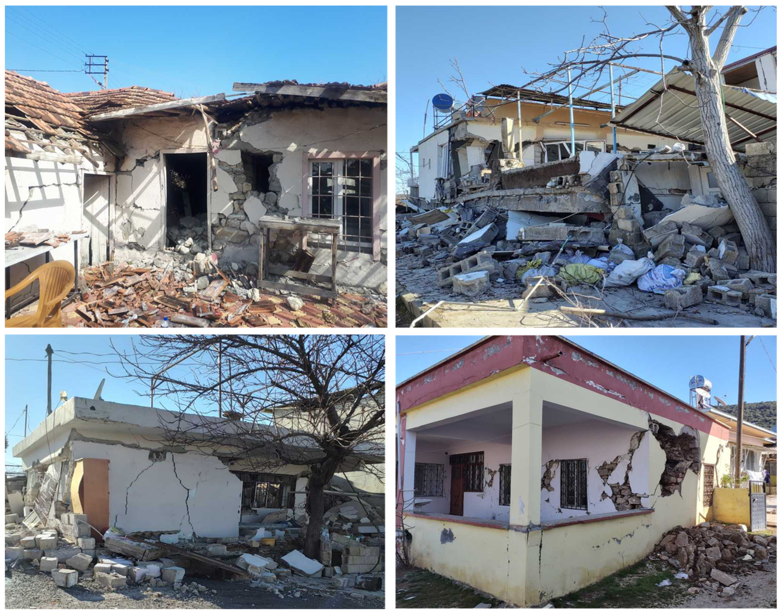
3.4. Failures at Corners and Orthogonal Wall Intersections
The failure of corners and intersections formed by orthogonal walls represents a common mode of failure in masonry constructions found in eastern Türkiye. In the presence of lateral seismic forces, inadequate interlocking, a deficiency or absence of vertical confining elements, and inconsistent detailing at L-, T-, or cross-shaped junctions significantly increase the vulnerability of these regions to sudden out-of-plane movements or corner disintegration [
45]. The fundamental geometry of masonry corners, typically characterized by substantial unreinforced edges converging at right angles, intensifies stress concentrations, especially during bidirectional ground shaking. As a result, the edges of walls are prone to rotate outward, leading to partial collapses that compromise structural integrity and produce dangerous debris fields.
Empirical observations consistently indicate that corner failures are intricately associated with two primary deficiencies. Firstly, masons frequently neglect to ensure the proper toothing or keying of perpendicular walls, resulting in vertical seams or discontinuities at the juncture [
45]. This issue stems from inadequate craftsmanship, where the builder fails to systematically interlace bricks or stones, and occupant expansions, wherein newly constructed perpendicular partitions are simply placed against rather than securely bonded to existing walls [
41].
During significant horizontal ground motion, these unbonded seams serve as planes of vulnerability; separation commences at mid-height or near the eaves, leading to the detachment of substantial triangular or indiscrete trapezoidal corner segments. Secondly, the lack of vertical confining elements, such as boundary tie columns, considerably exacerbates the deficiency of interlocking. Although partial interlocking of components may exist, in the absence of a substantial reinforced concrete (RC) or steel boundary element, the corner remains essentially unrestrained, allowing for out-of-plane rotation. Once fissures develop in the corner region, whether induced by out-of-plane bending or diagonal shear, there is no secondary confinement to restrict movement or maintain the corner’s structural integrity [
46]. As a result, cracks can swiftly advance from one surface to another, leading to complete corner “spalling” and localized failure. Field evidence indicated that cracks typically started at vertical seams where orthogonal walls lacked toothing or interlocking, often just below roof eaves or around unconfined window corners. From these points, fractures propagated diagonally downward or vertically along mortar joints, leading to the progressive detachment and outward rotation of entire corner segments under repeated lateral shaking.
In addition to their inherent structural disjunction, corner failures incite a cascade of adverse effects that jeopardize neighboring wall panels and floor diaphragms. Corners are typically pivotal nodal points essential for facilitating “box action”, enabling the transfer of lateral loads across perpendicular planes [
39]. Upon the fracturing or outward rotation of a corner, the overall capacity for distributing lateral forces experiences a significant reduction. Adjacent walls become isolated components vulnerable to out-of-plane instability, and roof/floor systems secured at that corner face the risk of partial detachment or progressive collapse in response to further seismic activity or aftershocks [
4].
The insights derived from the 2020 Sivrice and 2023 Kahramanmaraş earthquakes provided an abundance of case studies illustrating scenarios wherein multi-story stone or brick masonry structures demonstrated significant corner degradation. In buildings devoid of ring beams or horizontal tie beams, corner separation often coincided with the outward rotation of the upper segments of perpendicular walls. This dual-plane phenomenon exacerbated rescue operations, as precariously balanced corner segments posed a risk of collapse due to subsequent seismic activities or human-induced vibrations. Moreover, expansions initiated by occupants frequently resulted in the formation of new corners, which were connected solely through friction or insufficient mortar. These newly created corners exhibit distinct responses to seismic shaking compared to the original walls, thereby exacerbating corner separation. Post-event field investigations revealed diagonal shear fractures that abruptly deviate along joints installed by occupants, ultimately leading to sudden corner dislodgement.
Figure 14 shows field observations for failures at corners and orthogonal wall intersections.
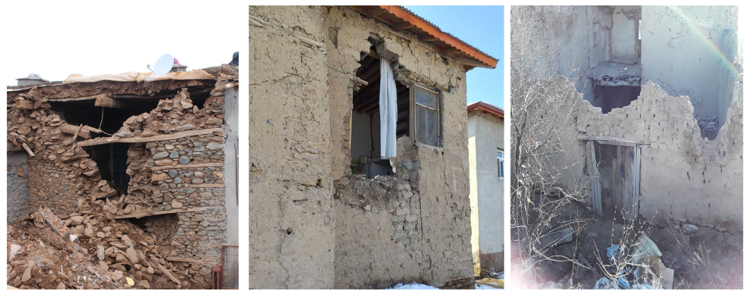
3.5. Observed Structural Failures Attributed to Occupant Expansions
Analytical evaluation of post-earthquake reconnaissance reports following significant seismic occurrences in eastern Türkiye, such as the 2011 Van earthquake, the 2020 Elazığ–Sivrice event, and the 2023 Kahramanmaraş earthquakes, reveals a recurring theme: unregulated alterations and expansions by occupants significantly contribute to the structural weaknesses of URM homes. These modifications, often implemented without professional engineering guidance or proper municipal regulation, result in sudden variations in mass distribution, structural stiffness, and the efficiency of lateral load transfer mechanisms [
3,
11,
41,
44].
In instances of vertical expansions, where an additional story is constructed on top of an existing structure, failures predominantly originate at the junction where the original walls meet the newly added upper level. These expansions frequently lack the necessary structural reinforcements, such as ring beams or adequate mechanical anchoring, at the wall-to-roof interface. Further weakening structural integrity is the new masonry, which is usually created with HCT units or partly heated bricks connected with weak, friction-based mortar.
Figure 15 shows a relevant example from the February 2023 earthquakes showing a situation where a second-story extension constructed using HCTs suffered total collapse, whereas the underlying story, made of rubble stone masonry, survived with minor damage. The root cause of failure was identified at the interface of the expansion, where continuity of the ring beam and vertical confinement were absent.
Horizontal expansions, including additions such as kitchens, living areas, or storage spaces, have been identified as contributing factors to structural instability. These modifications usually necessitate the creation of new openings in existing load-bearing walls to facilitate connections between the new and existing structures, resulting in a significant reduction of the in-plane shear capacity. Empirical observations, particularly after the seismic events in Elazığ in 2020 and Van in 2011, showed that expansion walls built with ungraded stone or adobe were often just set against pre-existing walls without suitable integration techniques including toothing, tie columns, or ring beams. A lack of interlocking and structural confinement caused the development of vertical planes prone to failure. These damaged interfaces were focal areas for crack initiation during seismic events, with diagonal or vertical cracks running through the expansion joints, therefore compromising the integrity and stability of the newly added sections.
It is essential to note that the failures attributable to structural expansions were not confined to a single seismic event. The analysis of four distinct earthquakes, including the 2020 Sivrice earthquake, revealed a consistent pattern: reconnaissance teams observed instances of collapsed or significantly compromised expansions, whereas the original masonry cores remained intact. Certain extensions raised building height over the story-height-to-thickness ratios approved by the TBEC (2018) [
13]. In other cases, these changes resulted in the removal of vital shear piers and the installation of extended unsupported wall sections, all in an attempt to generate more internal space. Furthermore, in most instances, the expansion operations were carried out without the supervision of official licenses, inspections, or seismic design assessments, which highlights the widespread lack of visibility for these changes within the current regulatory framework.
The extensive prevalence of these factors, combined with their exclusion from engineering assessments and the absence of formal regulatory scrutiny, highlights a significant deficiency in the policies aimed at mitigating seismic risks. To effectively bridge this gap, it is imperative to reconcile the performance standards set by national seismic codes with the actual conditions of Türkiye’s current infrastructure.
4. A Progressive Chronicle of Masonry Provisions in Turkish Earthquake Codes (1940–2018)
The discussion of damage mechanisms presented earlier primarily pertains to structures that have not been designed or constructed in alignment with seismic regulations. However, this circumstance does not lessen the importance of examining the TBEC (2018) [
13]. Instead, the significance of delineating TBEC (2018) [
13] provisions lies in providing a regulatory framework that allows for a critical evaluation of the identified shortcomings of construction practices. This section aims to emphasize the contrast between the established seismic safety regulations and the prevalent informal, occupant-led construction methods observed in the rural and peri-urban areas of eastern Türkiye. The analysis of recurring structural failures, such as the lack of ring beams, the use of inferior mortar, and excessive wall slenderness, can be elucidated by assessing how these practices diverge from the standards set forth in the TBEC (2018) [
13]. By engaging in this examination, the analysis makes clear that the pervasive vulnerability of masonry buildings is not merely a consequence of the absence of regulation, but instead a result of inadequate incorporation, execution, and enforcement of the existing standards within informal construction practices.
Earthquake design standards of Türkiye have been impacted by several seismic events and technical advances over many decades, resulting in a sequence of codes produced from 1940 to 2018. Turkish seismic rules have changed significantly in conceptual underpinnings and prescriptive criteria, particularly for masonry, from the basic principles of the 1940s to the TBEC (2018) [
13]. The rules set in 1944 [
47], 1949 [
48], and 1953 [
49] mostly repeated the 1940 standards, although they clarified mortar strength, stone measurements, and the importance of using local resources.
By 1961 [
50], multi-story masonry was explicitly recognized, but it still lacked quantitative standards for wall slenderness or ring beams. In reaction to earthquakes like the 1971 Bingöl disaster, the 1975 [
51] code stressed ring beams (hatıl) as a key approach to prevent out-of-plane failures, but did not impose them outside urban areas. The 1992 Erzincan earthquake and the recognition that occupant-driven expansions often circumvented structural regulation led the code to set stricter numerical limits on story height-to-thickness ratios and partial restrictions on earthen mortar by 1997 [
52,
53]. Inspired by research from the 1999 Kocaeli earthquake, the 2007 [
54] code mandated the use of ring beams in areas of moderate-to-high seismic activity and introduced preliminary capacity-based methods for the construction of reinforced or partially confined masonry.
The TBEC (2018) [
13] replaced zone-based hazard classifications with spectral acceleration maps, created explicit performance objectives (such as “Limited Damage” and “Collapse Prevention”), and required multi-story masonry structures to have continuous ring beams and tie columns. Occupant-driven extensions are still unclear in the 2018 [
13] code, allowing many rural or informal masonry additions to occur without code enforcement. Even as it struggles to reconcile code theory with practical application on-site, the Turkish regulatory framework for masonry has gradually evolved from basic prescriptive directives to comprehensive numerical constraints and performance-oriented principles.
Table 1 summarizes how key regulatory deficiencies in past Turkish seismic codes have directly contributed to observed failure mechanisms in the field, highlighting the practical implications of these gaps for URM construction.
The 2018 version delineates four degrees of seismic ground motion: DD-1, DD-2, DD-3, and DD-4. These values correspond to earthquakes with probabilities of exceedance of 2%, 10%, 50%, and 68% over a 50-year return period. Furthermore, the building significance coefficient (I) is used to delineate three building occupancy categories (
BKS): BKS = 1 pertains to critical infrastructures that must remain intact after seismic activity, including hospitals, educational institutions, and government facilities; BKS = 2 pertains to structures like retail centers and sports complexes; and BKS = 3 includes residential, commercial, and hospitality establishments. The latest version includes eight earthquake design classes (
DTS): DTS = 1–4 and 1a–4a. These classes pertain to the short-period spectral acceleration
of the DD-2 earthquake level and are associated with the previously established BKSs. This relationship is shown in
Table 2.
Based on the previously established DTS classifications, the TBEC 2018 delineates eight categories of building height (
BYS). Structures classified as BYS = 1 are characterized by an overall height that surpasses 70 m. Such edifices can be erected on sites exhibiting SDS values ranging from 0.50 to 0.75 and are categorized under DTS = 1, 1a, 2, and 2a. The relationship between DTS and BYS is presented in
Table 3. Additionally, masonry constructions are assigned BYS values of 7 and 8, where the potential variation in building height is contingent upon the DTS value of the respective site.
4.1. Material Eligibility and Standardization
Which masonry compounds are allowed and how they should be standardized has been vital for URM structural integrity throughout variations in Turkish seismic laws. The 1940 code, which established modern legislation in this area, allowed the use of stone, adobe, and “partially fired” bricks without setting compressive strength or mortar composition standards, leaving rural builders to use traditional methods. The 1944 [
47], 1949 [
48], and 1953 [
49] versions recommended “better shaped stones” or “semi-industrial” bricks but did not require thorough testing. Earthen mortar was accepted in single-story applications in these mid-century papers, showing indigenous materials’ societal supremacy rather than scientific engineering.
When revised in 1961 [
50], the code initially advised against using clay mortar in multi-story structures but allowed it in single-story homes. This method acknowledged that occupant expansions or partial augmentations were not clearly defined. The 1975 [
51] code mandated that “units must be of sound manufacture”. This let communities adopt partly burnt bricks or better stone manufacturing methods without setting numerical compressive restrictions. To establish binding minimum compressive strength criteria (≥5 MPa) for multi-story masonry, the 1997 [
52] code initially used national standards (e.g., TS 705) for bricks. Therefore, tenant expansions that impacted load-bearing walls in moderate- or high-seismic-risk areas were implicitly assumed to follow these criteria, despite variable local enforcement. The 2007 [
54] code established mortar classifications (M2.5, M5, and M10), penalized the use of earthen mortar in moderate- or high-risk areas unless heritage exemptions were applicable, and tightened HCT geometry and rebar anchorage specifications.
The TBEC (2018) [
13] allows four categories of masonry structures: URM, CM, RM, and RAAC. According to
Table 4, these structures must be constructed with poor ductility at the allowable BYS values. If a URM building is under construction, the allowable BYS is 8, equating to a maximum total height of 7 m for DTS categories 1, 1a, 2, and 2a, and 10.5 m for DTS categories 3, 3a, 4, and 4a.
Furthermore, the TBEC (2018) [
13] mandated M5 mortar in moderate- and high-seismic-risk zones, TS EN 771-1 [
55] HCT manufacturing requirements, and site-specific or laboratory testing for multi-story or occupant additions. The TBEC (2018) [
13] prioritizes standardized material evaluation as a primary condition for code adherence, which theoretically reduces the unchecked implementation of low-strength stone or earthen mortar that prior codes allowed. However, occupant expansions in isolated regions often evade systematic laboratory assessments, maintaining the discrepancy between sophisticated regulatory frameworks and localized construction practices.
Table 5 compares the TBEC (2018) [
13] with major international seismic codes, highlighting alignments and critical gaps, particularly in the regulation of URM design, retrofit strategies, and the treatment of informal construction practices.
Although the TBEC (2018) [
13] introduces modern seismic design standards, its impact in rural and peri-urban areas remains limited by gaps in enforcement. In many of the affected regions, local authorities face challenges like understaffing, limited budgets, and difficult access to dispersed settlements. As a result, formal inspections are rare, especially for small-scale additions made by homeowners themselves. Conversations with residents and municipal officials after the 2023 earthquakes revealed that permits are often skipped entirely for minor expansions, and inspections, when they occur, are sometimes reduced to routine paperwork. This lack of oversight means that even well-intentioned regulations often fail to reach the structures most at risk. Without meaningful on-the-ground enforcement, occupant-driven expansions continue to be built without seismic safeguards, leaving homes vulnerable despite the existence of a technically sound code.
4.2. Mortar Classes, Joint Thickness, and Masonry Unit Testing
In the mid-twentieth century, Turkish seismic regulations provided merely a qualitative recognition that “sufficient” mortar should be utilized, generally referring to lime or cement–lime compositions without delineating minimum compressive strengths or joint dimensions. Indeed, within the codes from 1940 to the early 1960s, creating earthen mortars was deemed an acceptable practice for single-story structures, whereas multi-story masonry remained sufficiently infrequent that numerical benchmarks for mortar strength or joint dimensions were overlooked. By 1975 [
51], the regulatory language became more precise in advocating for “well-made” mortar and “consistent joint thickness”, although it had yet to mandate formal compressive testing or numerical classifications (e.g., M2.5, M5). Often, discretionary site assessments were deemed adequate, with expansions by occupants, particularly in rural southeastern Türkiye, continuing to evade official documentation, thereby escaping scrutiny regarding mortar quality.
The 1997 [
52] modification was the first instance in which the code included a quasi-quantitative standard for minimum mortar strength in load-bearing walls, establishing an insufficient relationship to national or local testing standards. The 2007 code [
53] formalized this shift by specifying defined mortar “classes”, including M2.5, M5, and M10, and stating that multi-story masonry or masonry in moderate-/high-seismic-risk areas must at least be of class M5. This code established guidelines for joint thicknesses, often necessitating bed joints of around 10–15 mm and mandating consistent bed and head joints to mitigate shear-plane weaknesses. Nevertheless, occupant expansions continued to disregard or minimize these needs, since unlicensed projects seldom passed laboratory or site-based compressive testing.
By the TBEC 2018 [
13], mortar categorization transitioned to a definitive numeric standard, requiring class M5 or above in zones of moderate-to-high seismic activity, with compressive strengths of about 5 MPa. The references to standardized tests, often using TS EN 1015-11 [
59] techniques, indicated that the code now regarded systematic laboratory or field testing as essential for validating consistent mortar performance, particularly in multi-story URM or RM. Simultaneously, the maximum joint thickness (≤15 mm) and guidelines for adequately compacted head joints were established. Notably, while tenant expansions are required to comply with these regulations, the legal classifications for “partial additions” sometimes enable them to bypass formal building permits. Furthermore, the TBEC (2018) [
13] establishes regulatory parameters for the permissible minimum and maximum thickness measurements of load-bearing walls, as delineated in
Table 6.
As a result, the progressive methodology advocated by the TBEC (2018) [
13], which incorporates standardized mortar classifications, numerical compressive limits, and constrained joint thicknesses, has not achieved consistent implementation on site in numerous rural developments, where traditional friction-based or earthen mortar practices persist. Nevertheless, the systematic definition of mortar classifications, enhanced joint thickness regulations, and mandated testing of masonry units represent significant advancements in Turkish seismic regulations over the last fifty years.
4.3. Ring Beams (Hatıl) and Confining Elements
Earlier versions of the Turkish earthquake regulations at most briefly referenced “belt courses” or “reinforced tie layers”, seldom explicitly designating them as ring beams (hatıl) and providing little information on their integration into masonry walls. Between 1944 [
47] and 1961 [
50], the rules included only broad recommendations for additional horizontal supports in multi-story or corner-heavy structures, without specific requirements for rebar diameter or cross-sectional depths. The 1975 code [
51] clearly identified ring beams as essential for preventing out-of-plane failure, but it mostly provided suggested guidance for their thickness and anchorage. Although the law acknowledged that residential expansions including additional floors should ideally use ring beams, it refrained from mandating local authorities to enforce this requirement in isolated regions.
By 1997 [
52], ring beams became firmly stated as a necessary component for multi-story URM. Yet, the code continued to allow single-story stone or adobe structures to bypass ring beams if local officials deemed them safe. Occupant expansions frequently leveraged this oversight, adding rooms or entire upper floors without integrating horizontal beams. In a similar vein, although the 1997 [
52] code did reference minimal ring beam cross-sectional areas, it did not stipulate anchorage details, stirrup spacing, or splicing lengths.
The 2007 [
54] code brought these confining elements to the forefront, requiring that any multi-story URM in moderate- or high-seismic-risk zones implement ring beams at every floor level. In addition, it proposed corner tie columns or vertical boundary members to confine the walls into box-like segments. This partial capacity design logic also meant ring beams had to meet some fundamental rebar continuity standards. Even occupant expansions that involved new floors in moderate-/high-risk areas technically needed ring beams retrofitted onto the older walls to ensure load path integrity. Notwithstanding these rules, code enforcement continued to be a weak link: occupant expansions often remained outside formal permissions, particularly in rural or semi-urban areas.
The TBEC (2018) [
13] refined these ring beams and confining element requirements further, mandating minimum cross-sectional heights and rebar coverage for ring beams in moderate-/high-risk zones, and calling for vertical boundary columns around large openings or corners. The code introduced more standardized approaches to confining masonry, especially when combined with improved mortar classes and more stringent analysis methods. However, occupant expansions still received no separate recognition in law, thus generally remaining unverified unless the homeowner voluntarily complied. Mandatory requirements related to ring beams are illustrated in
Figure 16.
Additionally, the TBEC (2018) [
13] stipulates that the minimum cylindrical compressive strength of these ring beam (hatıl) components should be no less than 25 MPa. The code stipulates that a minimum thickness of 10 cm for reinforced concrete slabs must include transverse reinforced horizontal beams to ensure that URM, RM, and CM structures achieve rigid diaphragm behavior. The vertical distance of the horizontal ring beams is limited to a maximum of 4 m.
4.4. Wall Slenderness, Story Height, and Openings
The progressive amendments concerning wall slenderness, permissible floor heights, and allowable openings within Turkish seismic regulations demonstrate a gradual evolution from ambiguous, experience-based standards to comparatively precise numerical limitations. As illustrated by the codes of 1944 [
47], 1949 [
48], and 1953 [
49], references to maximum wall heights or thicknesses were predominantly articulated in qualitative terms, such as advocating for “adequate thickness” to ensure the stability of stone or adobe constructions, while formal floor height regulations were seldom more detailed than suggesting single-story structures for earthen mortar. The 1961 [
50] revision marked a subtle recognition of multi-story masonry, albeit reiterating broad recommendations that walls must not be “unduly slender” and granting limited authority to local administrations to evaluate occupant additions on an individual basis. A significant transformation occurred with the 1975 [
51] code; it introduced preliminary numerical criteria for multi-story masonry, recommending specific height-to-thickness ratios, typically not exceeding 12:1 or similar, especially in moderate-to-high-seismic-risk zones, although expansions involving additional upper floors remained largely outside rigorous municipal oversight.
By 1997 [
52], the code stated more explicit constraints, assigning maximum H/t (height-to-thickness) ratios for unreinforced stone or brick walls (e.g., 10:1 or 12:1 in some official or local guidelines) and demanding that multi-story URM carefully respects these limits to reduce diagonal shear cracking and out-of-plane bending. At the same time, the 1997 [
52] text began referencing recommended story heights (generally 3.0 m or less for typical URM) and limiting window/door openings by specifying minimum piers to mitigate plane instability, although occupant expansions often introduced large new openings for interior remodeling without abiding by these constraints. The 2007 [
54] code built upon these numeric guidelines, tying them more concretely to seismic zones: moderate-to-high-seismic-risk areas might require an even stricter H/t ratio (e.g., 8:1 or 10:1), capping story heights at nearly 3.0 m and mandating that each opening remain within specified bounds (such as not exceeding 50% of the wall length). Multi-story occupant expansions in moderate/high-risk zones thus theoretically had to conform to these numeric slenderness and story height rules, but without a distinct “occupant expansions” category, application remained uneven.
Finally, the TBEC (2018) [
13] refined slenderness restrictions further, linking them to the performance-level objectives (Limited Damage or Collapse Prevention) for multi-story or confined masonry. This code also strictly limited openings, usually demanding a robust wall segment around doors and windows, and recommended corner piers of at least 0.80 m. By insisting that occupant expansions meet these same guidelines, the TBEC (2018) [
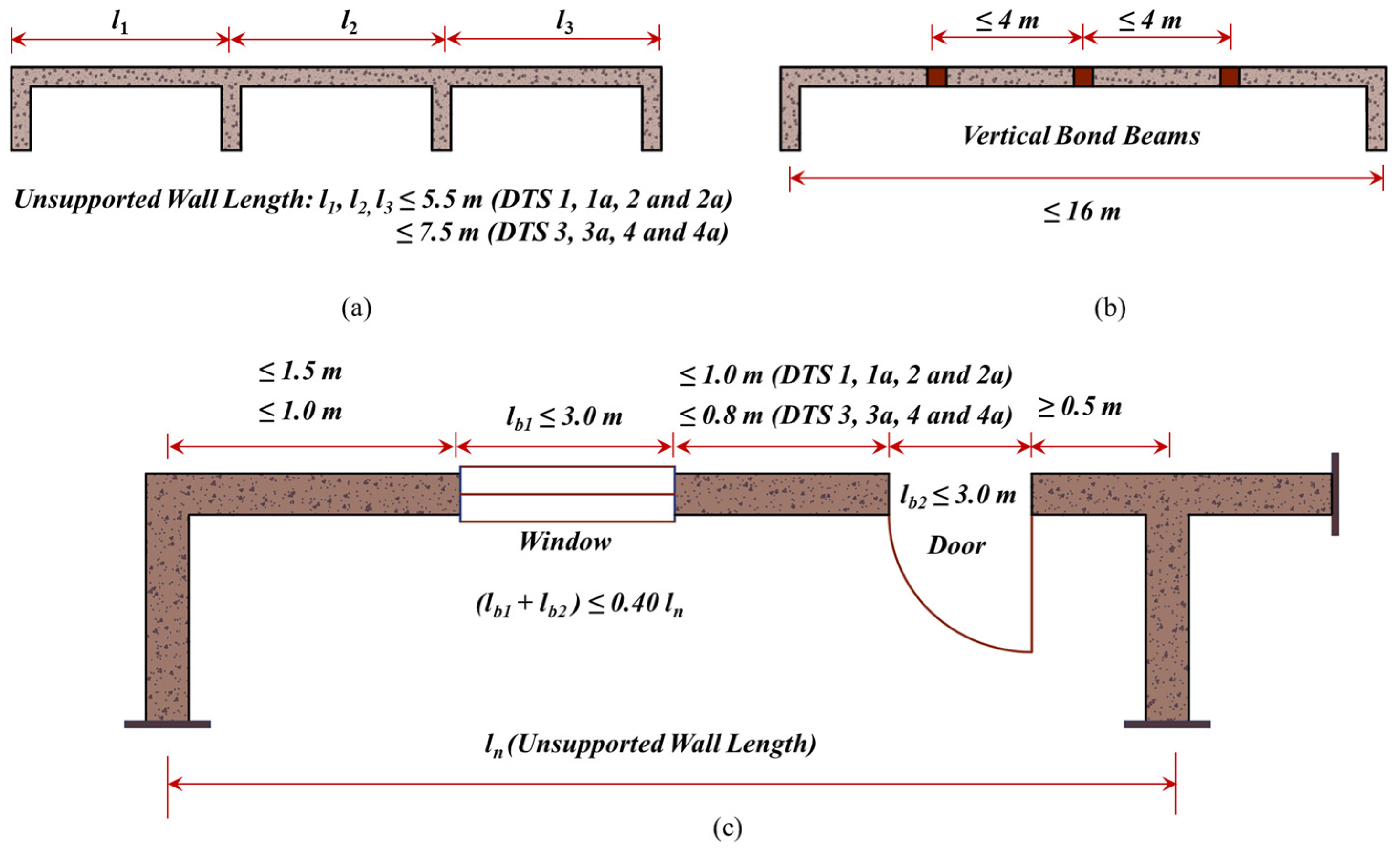
13] attempted to curb expansions that historically produced extremely slender walls, extensive openings, or additional stories without proportionate strengthening. In practice, occupant expansions still frequently occur under unlicensed conditions, thus undermining the code’s numerical, capacity-based approach to slenderness, story height, and opening limitations. The allowed unsupported wall lengths according to the TBEC (2018) [
13] are illustrated in
Figure 17.
4.5. Gable Walls, Heavy Earthen Roofs, and Special Roof Systems
Previous Turkish earthquake codes paid only cursory attention to gable walls and traditional earthen roofs, largely accepting them as local cultural norms rather than rigorously controlled design features. From 1944 [
47] through to the 1961 [
50] revision, references to gable geometry were effectively absent, and massive earthen roofs remained tolerated so long as single-story or low-rise contexts prevailed, as was common in rural Anatolia. Due to this hands-off approach, older documents merely advised that “excessive heights” or “unstable shapes” be avoided yet provided no numeric specifications to prevent out-of-plane tipping of gable walls or dangerously heavy roof structures. Consequently, occupant expansions frequently raised the overall roof mass or added new gables in an unregulated manner, thereby exacerbating the potential for partial or total collapse during seismic episodes.
By 1975 [
51], the code grew more explicit about limiting tall, unsupported gable walls. It stopped short of enumerating an absolute gable wall height, but it encouraged ring beams (hatıl) at the eaves level or the top perimeter. As for earthen roofs, the 1975 [
51] text vaguely warned that “excessive roof mass” significantly raised inertial demands on masonry walls, yet enforcement hinged on local building departments, which rarely forced rural homeowners to abandon the heavy earthen tradition. Occupant expansions that extended or modified roof lines often went beyond official scrutiny, enlarging roof mass with additional earth layers or partial second floors, while ignoring ring beam continuity at the ridges.
The 1997 [
52] code identified gable wall detachment as a recurrent failure mode. The text specified that gables in moderate-/high-seismic-risk areas should maintain limited height, recommended an eave-level ring beam, and if feasible, required tie columns at corners. Nonetheless, these clauses remained only partially mandatory, and occupant expansions continued to spawn non-compliant gables, especially where expansions introduced an entire second pitched roof. As for earthen roofs, the 1997 [
52] document acknowledged their cultural entrenchment but recommended that multi-story masonry rely instead on lighter systems or ensure ring beams that confine the top walls. In practice, local enforcement remained minimal, allowing occupant expansions to reinforce the older pattern of heavy earthen roofs with minimal structural ties. A schematic illustration of a heavy earthen roof is given in
Figure 18.
A more rigorous stance on gable walls and heavy earthen roofs emerged in the 2007 [
54] code. The code nominally capped the height of gable walls, often requiring they remain below two meters above the last ring beam. It also advocated rebar anchorage to connect the gable apex to the underlying wall system. Simultaneously, the 2007 [
54] text took a firmer line against heavy earthen roofs in moderate-/high-risk zones, except under “special heritage” exemptions. Occupant expansions that added or raised pitched roofs were thus theoretically obligated to follow these new numeric restrictions, but in practice, occupant expansions typically proceeded without official notice in many rural communities, preserving the cycle of top-heavy roofs or tall, unconstrained gables.
Finally, the TBEC (2018) [
13] completed a shift to a more performance-oriented approach, explicitly restricting tall gable walls to around 0.8 to 1.0 m above the last horizontal beam in areas of higher seismic risk and pushing occupant expansions that altered pitched roofs to incorporate ring beams or partial steel ties if the roof mass exceeded certain recommended thresholds. Earthen roofs, while not outright banned, were declared “highly discouraged” in multi-story settings or moderate-/high-risk zones, necessitating ring beams and corner ties if used. Occupant expansions, in theory, must align with these disclaimers, but the code still fails to name expansions distinctly. Thus, the advanced numeric constraints on gable height and the strong discouragement of thick earthen roofing remain difficult to enforce for occupant expansions in low-administration locales.
4.6. Occupant Expansions and Systematic Code Non-Compliance
Post-earthquake reconnaissance confirms that most catastrophic failures observed in rural and peri-urban Anatolia can be traced to unlicensed occupant expansions, vertical or horizontal additions executed without formal design review. In the 2023 Kahramanmaraş sequence, 64% of the collapsed dwellings inspected in Pazarcık and Nurdağı exhibited at least one expansion that violated the length-to-thickness limit or lacked the ring-beam continuity mandated by the TBEC (2018) [
13]. Similar patterns were documented after the 2020 Elazığ–Sivrice and 2011 Van events, where out-of-plane gable failures and corner spalling were concentrated in houses whose owners had lengthened façades beyond ten times the wall thickness without adding the intermediate tie columns required by the code.
Three interacting factors perpetuate this systematic non-compliance. Economic constraints encourage owners to reuse local stone, earthen mortar, and salvaged timber, materials that do not meet the M5 mortar class or compressive strength threshold stipulated before. Administrative blind spots allow small additions, typically < 30 m2, to proceed under simplified “renovation” permits that do not trigger structural review, even though these additions often raise the building from BKS IV to BKS III and thereby increase the required analysis rigor. Cultural preference for incremental self-building means that ring-beam steel or laboratory mortar testing is perceived as an unnecessary expense for a “temporary” first-floor room, even though such expansions frequently become permanent.
The divergence between code intent and on-site reality is therefore not a marginal issue but a dominant driver of seismic loss in Turkish masonry stock. Each unreinforced expansion alters load paths, increases diaphragm demands, and nullifies the performance-level objectives, Limited Damage and Collapse Prevention, that the TBEC (2018) [
13] prescribes for the parent structure’s original DTS and BYS combination. Until occupant expansions are recognized in municipal bylaws as structural interventions requiring ring beams, tie columns, and mortar verification, even when the footprint increment is modest, the TBEC (2018)’s [
13] advanced capacity-based provisions will remain only partially effective outside major urban jurisdictions.
In conclusion, the comprehensive analysis of the provisions within the Turkish seismic code extends beyond a mere historical or regulatory summary; it establishes an analytical lens through which the systemic vulnerabilities in the construction sector can be evaluated. The observed deficiencies in masonry buildings, particularly those linked to unauthorized expansions by occupants, cannot be solely blamed on a lack of technical guidance. Instead, they highlight the inadequacy of existing regulations to infiltrate informal construction practices. This disjunction emphasizes the urgent necessity for more inclusive and enforceable regulatory approaches that recognize the prevalent presence of unauthorized additions and self-constructed structures. Addressing this regulatory shortfall is crucial for ensuring that seismic codes fulfill their intended protective roles, particularly in contexts beyond formally engineered structures.
Despite the evolution of Turkish seismic codes, the persistent vulnerability of masonry buildings cannot be addressed by regulation alone. In many rural and peri-urban areas, the implementation of the TBEC (2018) [
13] is hindered by institutional limitations, including understaffed municipal offices, the scarcity of licensed structural engineers, and the lack of accessible training for local masons. Official permitting procedures are often bypassed for small additions or expansions, and in some provinces, permit approvals are handled by general technicians or non-engineering staff with limited capacity to assess structural implications. According to reports by Türkiye’s Chamber of Civil Engineers (TMMOB) [
60], a significant portion of rural municipalities operate without a full-time civil or structural engineer, relying instead on rotating or part-time staff from provincial centers. These constraints result in inconsistent application of the code and allow many non-compliant structures to proceed unchecked. Without targeted policy interventions such as staffing incentives, mobile inspection units, or simplified permit pathways with structural safeguards, the TBEC’s advanced provisions will remain out of reach for much of the building stock that needs them most.
5. Conclusions
With particular emphasis on failures resulting from occupant-driven expansions and departures from seismic code requirements, this paper offers a thorough investigation of the seismic vulnerability of URM homes in eastern Türkiye. Based on field data from past and current earthquakes, the study shows how informal construction methods, especially the lack of ring beams, use of non-compliant mortar, and omission of vertical tie components, undermine structural integrity even in low-to-moderate-rise buildings.
The results show that structural breakdowns are not just the outcome of obsolete construction practices or material constraints but also the consequence of a systematic divergence between formal regulatory systems and the reality of rural building activity. Although the TBEC (2018) [
13] calls for accurate seismic performance criteria, including wall slenderness ratios, mortar classification, ring beams, and confinement detailing, occupant expansions often treat these requirements as non-structural interventions and often ignore or avoid them, compromising their notable load-bearing effects.
The creation of
Appendix A, which combines technical material in a homeowner-accessible manner, is one of the major contributions of this work. This appendix connects expert knowledge to practical advice by converting technical failures into a table of field-observed problems, related damage processes, and straightforward retrofitting remedies. It emphasizes the necessity of a new type of community-oriented seismic literacy that supports regulatory change.
Ultimately, the paper contends that not only improvements in code complexity but also the official acknowledgment of informal building realities will be necessary for significant seismic risk reduction in Türkiye’s brick dwelling sector. Structural extensions have to be viewed as seismic interventions and held to fundamental engineering standards. Municipal control should be enhanced; records of important design practices should be made readily accessible in a simpler, illustrated manner. The method shown here offers a scalable outreach strategy as well as a diagnostic framework, maybe relevant to other seismically active areas with high degrees of informal building.
While this study offers a detailed look at how masonry buildings performed during recent earthquakes, it is important to be upfront about its limitations. The damage assessments were carried out in the immediate aftermath of the 2023 Kahramanmaraş events, under field conditions that did not allow for lab testing or the use of specialized tools like Schmidt hammers or core extraction. As a result, many of the evaluations relied on visual inspections and pattern recognition rather than precise measurements. Also, while trends were observed, such as the link between unreinforced expansions and structural failure, these relationships were not backed by statistical modeling or numeric correlation. Future studies could build on this work by incorporating more standardized assessment methods, detailed material testing, and broader datasets. Doing so would help not only validate the patterns noted here but also support more targeted retrofit guidelines and practical policy solutions.


