Article

Numerical Optimization of Laser Powder Bed Fusion Process Parameters for High-Precision Manufacturing of Pure Molybdenum

by
İnayet Burcu Toprak
1,
Nafel Dogdu
1,* and
Metin Uymaz Salamci
2,3
1
Vocational School of Technical Sciences, Akdeniz University, 07070 Antalya, Türkiye
2
Department of Mechanical Engineering, Gazi University, 06570 Ankara, Türkiye
3
Additive Manufacturing Technologies Application and Research Center, Gazi University, 06980 Ankara, Türkiye
*
Author to whom correspondence should be addressed.
Appl. Sci. 2025, 15(10), 5485; https://doi.org/10.3390/app15105485
Submission received: 7 April 2025 / Revised: 8 May 2025 / Accepted: 9 May 2025 / Published: 14 May 2025
(This article belongs to the Section Additive Manufacturing Technologies)

Abstract

:
This study presents a comprehensive numerical investigation of the Laser Powder Bed Fusion (LPBF) process for pure molybdenum, focusing on high-precision modeling and process optimization. The powder spreading behavior is simulated using the Discrete Element Method (DEM), while molten pool dynamics are analyzed through Computational Fluid Dynamics (CFD). Optimization of process parameters is performed using FLOW-3D Release 7 software in conjunction with the HEEDS-SHERPA algorithm. A total of 247 simulations are conducted to assess the effects of four critical parameters: laser power (50–400 W), scanning speed (80–300 mm/s), laser spot diameter (40–100 µm), and powder layer thickness (50–100 µm). The optimal parameter set—350 W laser power, 120 mm/s scanning speed, 50 µm spot diameter, and 50 µm layer thickness—results in an 80% laser absorption rate, a 60% reduction in micro-porosity, and over a 30% enhancement in both molten pool volume and surface area. Utilizing a fine 10 µm mesh resolution enables detailed insights into temperature gradients and phase transition behavior. The findings highlight that optimized parameter selection significantly improves the structural integrity of Mo-based components while minimizing manufacturing defects, thus offering valuable guidance for advancing industrial-scale additive manufacturing of refractory metals.

1. Introduction

Molybdenum (Mo), with its high melting point (~2620 °C) and exceptional mechanical properties, stands out as a critical material for next-generation high-temperature applications. Current nickel-based super alloys used in jet engines operate at temperatures around ~1150 °C (close to 90% of their melting point) and are insufficient for higher temperature requirements [1]. In this context, molybdenum, a refractory metal, has attracted attention as a potential material for use in the plasma-exposed inner walls of fusion reactors [2] and electronic packaging components requiring high thermal conductivity and low thermal expansion [3].
However, the traditional powder metallurgy methods for producing molybdenum face several limitations in manufacturing complex geometries and small-scale parts. As a result, the Laser Powder Bed Fusion (LPBF) method, which allows for mold-free production and the direct fabrication of complex geometries, is gaining increasing importance [4]. It has been demonstrated that Mo parts produced by LPBF exhibit high geometric precision, fine-grained structures, and superior mechanical performance compared to conventional manufacturing methods [5].
Nevertheless, due to Mo’s high melting point, high reflectivity to laser radiation, and brittle nature, common production defects such as cracking, balling, and porosity are frequently reported in LPBF processes [6,7]. Furthermore, oxide layers on the surface reduce the wettability of the melt pool, negatively affecting part quality [8,9]. Strategies to reduce cracking, such as the addition of nanoparticles [10], carbon alloying [11], and preheating the material before processing [12], have been proposed.
Recent studies have shown that high-density pure Mo parts can be produced with porosity levels above 99% [13,14]. However, LPBF processing of advanced alloys such as Mo–Si–B still presents significant challenges. These alloys exhibit excellent mechanical and oxidation resistance at high temperatures but suffer from limited ductility at room temperature and poor oxidation resistance at intermediate temperatures [15]. In this regard, new phase designs and alloying approaches continue to be explored for improvement [16,17].
Numerical simulation models developed to better understand the LPBF process allow for detailed analysis of critical process parameters such as melt pool behavior, heat transfer, and solidification dynamics [18,19]. Additionally, high-resolution computational models have been employed to study complex flow regimes and gas void formation during the laser–metal interaction [20,21]. Recently, the integration of deep learning-based intelligent monitoring systems into LPBF has made it possible to detect manufacturing defects, such as powder spreading issues, in real time [22].
Several studies in the literature have focused on the LPBF processing of molybdenum. Wang et al. [7] achieved over 99% density by optimizing laser parameters but were unable to fully eliminate cracking. Braun et al. [6] concentrated on microcracks and melt pool instability in high-melting-point metals such as Mo and W during LPBF, yet they did not provide a detailed analysis of temperature gradients. Rebesan et al. [14] evaluated the mechanical and thermal properties of the produced Mo samples, but they worked with a single set of parameters and did not model process dynamics. Similarly, Guo et al. [18] conducted simulations on melt pool and heat transfer; however, their study had a limited parameter space, and no correlation was made between model outputs and mechanical defects. Yakang et al. [15] provided a comprehensive review of Mo–Si–B alloys but did not address simulation-based solutions for the manufacturing challenges encountered in LPBF processing of these alloys. Thus, the existing literature mostly contains either experimental data or simulations with limited parameter combinations, with very few studies offering comprehensive and direct analysis based on physical results.
This study systematically and quantitatively analyzes the behavior of pure molybdenum during the LPBF process using a purely numerical simulation approach. While many studies in the literature have relied on experimental approaches or simulations with limited parameters, this study evaluates critical parameters such as laser power, scanning speed, powder layer thickness, and laser spot size over a broad range. Thermal outputs, such as melt pool geometry, temperature distribution, and solidification rate, are modeled in detail. As a result, this study not only determines the optimal process parameters but also develops a deeper understanding of the physical foundations of defects, such as porosity and cracking. In this regard, the study contributes to the optimization of the LPBF process independently of experimental costs and constraints, filling a significant gap in the literature regarding the applicability of refractory metals in additive manufacturing.
This study presents a unique and comprehensive numerical optimization framework for processing pure molybdenum via LPBF, integrating DEM-based powder modeling, CFD simulations, and the multi-objective HEEDS-SHERPA algorithm. While previous studies were limited to narrow parameter ranges or experimental designs, this work systematically explores 247 different parameter combinations to identify optimal regimes that significantly reduce porosity and enhance melt pool characteristics. This level of detail and numerical correlation has not been previously reported for refractory metals processed via LPBF. This level of detail and numerical correlation has not been previously reported for refractory metals processed via LPBF.

2. Method

This section provides a detailed discussion of the core components of the study, including numerical simulations, parameter selection, simulation procedures, and conditions. The scientific approach of the study, the rationale behind the methods used, and the steps taken to enhance the accuracy of the results are systematically explained.
In this study, the powder spreading process was modeled using the Discrete Element Method (DEM), while the molten pool dynamics were modeled using Computational Fluid Dynamics (CFD). Simulations were conducted using the FLOW-3D software, and process parameter optimization was performed using the SHERPA algorithm within the HEEDS MDO 2410 software. These widely accepted and established simulation methods are frequently applied in additive manufacturing research and have been validated by numerous previous studies [19,21].
Additionally, this section elaborates on the computational mesh structure and analysis methods employed to improve the accuracy of the numerical model.

2.1. Simulation Software
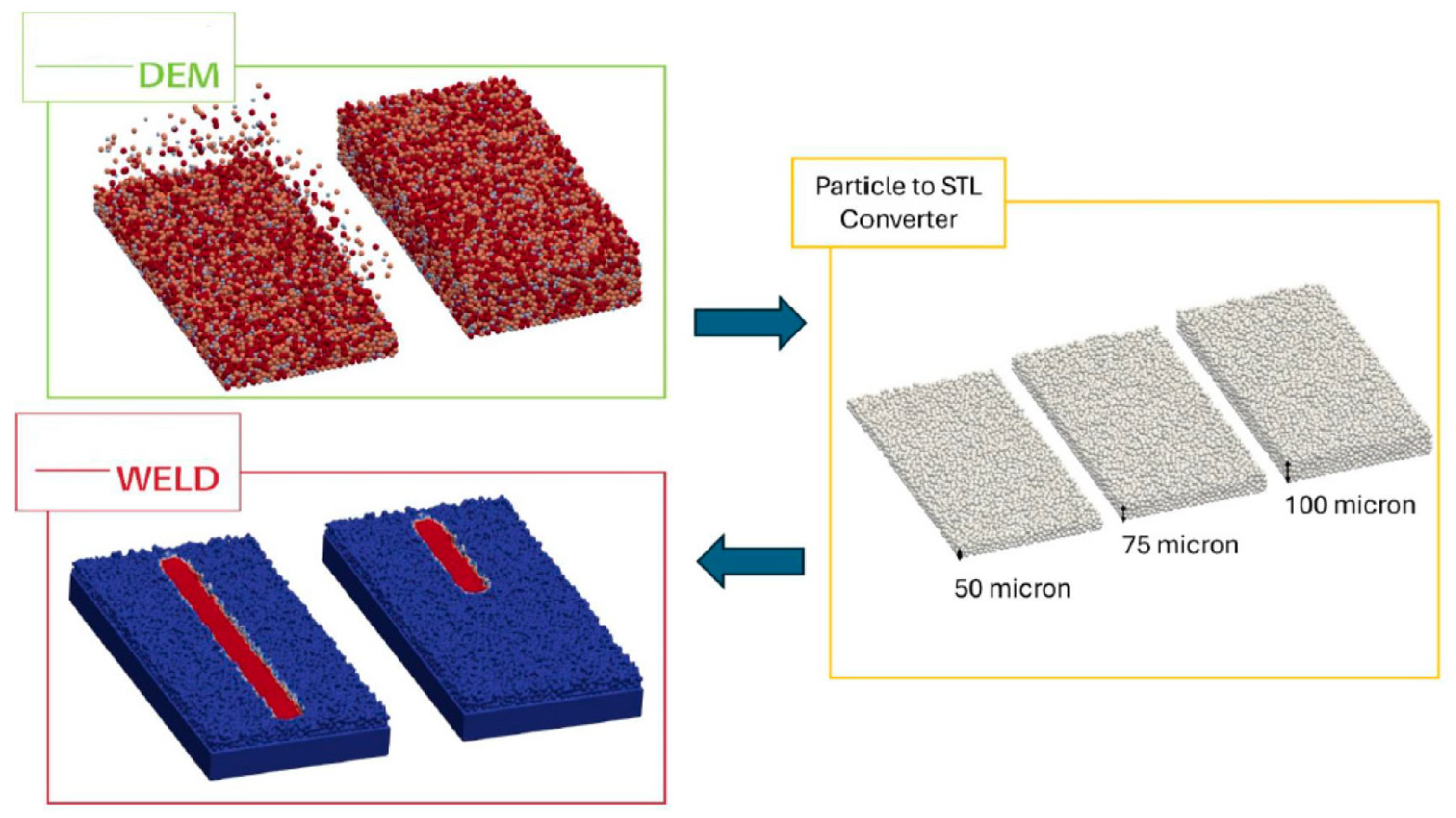
In the numerical simulations, CFD methodology was employed to accurately and comprehensively model the single-track structures in the LPBF process. This modeling approach enables a more precise analysis of the thermal effects of the laser on the material, melt pool dynamics, and solidification processes.
Additionally, for simulating the powder spreading process, the DEM was utilized. This allows for a more realistic examination of the interactions between powder particles and ensures a homogeneous particle packing. This approach enhances the accuracy and reliability of the simulations.
The material data used in the DEM and CFD simulations were obtained from Thermo-Calc 2024a software. Additionally, the particle size distribution was provided by Nanografi. The input parameters and boundary values defined for the HEEDS software were sourced from Gazi University’s Additive Manufacturing Technologies Application and Research Center, as well as simulation trials conducted by IOG Engineering. These data are crucial for accurately modeling the physical behavior of the material under LPBF conditions and ensuring the reliability of the simulation results.

2.1.1. DEM Model

The DEM is a powerful numerical simulation technique primarily used to analyze the dynamic behavior of particulate materials and particle systems. This method treats each particle as an individual solid body, calculating the interactions between particles and their environment at discrete time steps. DEM is commonly employed for modeling powder beds, granular materials, free-flowing particles, and compressible media.
In the DEM model, the translational and rotational movements of each particle are expressed according to Newton’s second law. When particles come into contact with each other, contact forces are calculated based on specific contact models. These models account for factors such as elastic collisions, plastic deformations, frictional forces, and adhesion. The force interactions between particles are typically computed using models based on Hertz-Mindlin contact theory or Hooke’s law.
Additionally, the DEM also considers the interactions between particles and their surrounding environment. For example, in modeling particles suspended in a fluid, the interaction between the fluid and particles is analyzed in combination with CFD, providing a more detailed understanding of the fluid-particle interactions.
Ultimately, the DEM is a highly effective approach for understanding the dynamics of particulate systems and realistically modeling particle movement in processes such as powder bed simulations. This technique plays a critical role in the modeling of the powder spreading stage in LPBF, assisting in the analysis of particle distribution, compaction mechanisms, and the homogeneity of the surface layer [19].

2.1.2. CFD Model

In this study, CFD is employed to model the laser melting process in detail. To accurately track the heat transfer, phase changes, and fluid dynamics occurring during the interaction between the laser and the material, the Volume of Fluid (VOF) method is integrated into the simulation to monitor the evolution of the free surface. This approach enables precise modeling of the dynamic behavior of the molten metal and surface deformations, thereby providing a deeper understanding of the key physical mechanisms involved in the process.
During the simulation, before the laser melting process begins, the Mo powder bed, created using the DEM, is assumed to be static. In this scenario, no particle movement is anticipated, and the initial conditions are set as a stable powder bed. Upon the application of the laser beam, the material begins to melt due to the high temperature, and the molten pool exhibits specific dynamic behavior. The shape and movement of the molten pool are influenced by various physical processes such as surface tension forces, thermal gradients, and phase transitions.
The absorption of the laser beam by the surface leads to a temperature distribution within the material, initiating localized melting. Due to temperature differences, heat is transferred between the solid and liquid phases, resulting in thermal gradients. Simultaneously, the flow within the molten metal facilitates the transport of hot metal to cooler regions, while thermal radiation emitted from the high-temperature areas contributes to the energy balance.
Changes in surface tension due to temperature variations on the surface trigger flow motions within the molten pool, playing a crucial role in determining the pool’s width and depth. During this process, a portion of the material may directly vaporize due to the high laser power and temperature, causing dynamic feedback at the molten pool surface. The resulting vapor pressure can lead to side effects such as metal spattering and micro-crater formation, which may affect the final quality of the structure.
This modeling approach, by analyzing the complex heat-fluid interactions and phase transformations within the laser melting process, provides valuable insights for quality control and parameter optimization in additive manufacturing processes such as LPBF. The CFD model contributes to a better understanding of the process and helps enhance the production quality [19].

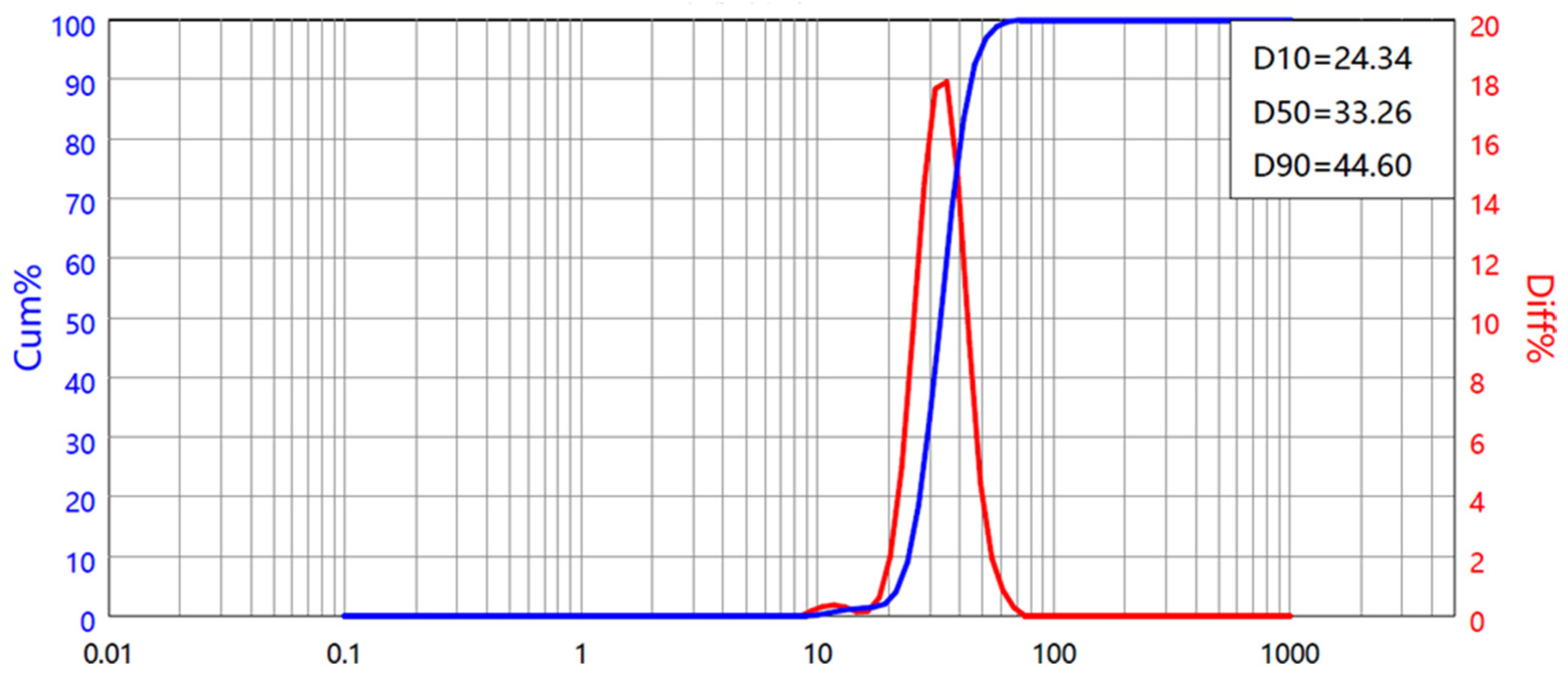
2.2. Characterization of Mo Powder

The molybdenum powder used in this study has a purity of 99.95% and exhibits a spherical morphology with a continuous particle size distribution. The powder, utilized in simulation studies, has a particle size distribution ranging from 15 to 45 µm, as specified by the manufacturer. The physical properties of molybdenum are presented in Table 1.
A detailed particle size distribution graph is presented in Figure 1.
When the minimum and maximum particle sizes are included in the list, the boundary values of the particle size groups are presented in Table 2.
Additionally, the volumetric proportions of the groups formed by taking the averages of the boundary values of the particle size groups are presented in Table 3.
The obtained volumetric fractions have been converted into numerical ratios in Table 4 for definition in the CFD.
The temperature and density-dependent properties of the material, as defined in the CFD, are presented in Figure 2a; temperature-dependent viscosity properties are shown in Figure 2b; temperature-dependent specific heat values are provided in Figure 2c; and temperature-dependent thermal conductivity is given in Figure 2.
The material property data shown in Figure 2 were obtained from Thermo-Calc software.

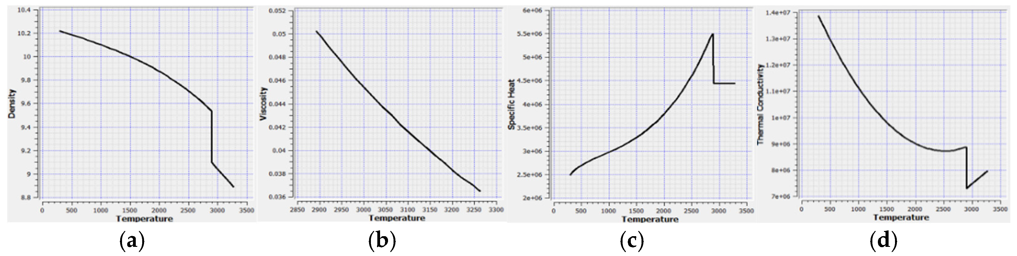
2.3. Simulation of Molybdenum Powders in the LPBF Process

To model the physical structure of the powder bed as accurately as possible, the powder geometry created via DEM simulation was converted into STL format. This approach enabled a more detailed analysis of the laser melting process, allowing the microstructure of the powder bed to be realistically represented in the simulation environment.
Furthermore, to ensure the accuracy of thermal distribution and fluid dynamics calculations in the simulation, the substrate thickness was set to 4 mm. This thickness allows for the realistic simulation of temperature differences that arise during the laser melting process, ensuring balanced heat distribution across the substrate. Additionally, using a 10 µm mesh resolution enabled more precise modeling of the dynamic behavior of the melt pool and surface tension effects. As a result, the temperature distribution, phase changes, and fluid movements in the laser-treated area were analyzed in detail, enhancing the physical realism of the simulation.
For the simulation, the temperature-dependent physical and thermal properties of Molybdenum (Mo) were integrated into the model using data obtained from the Thermo-Calc software. To accurately model the laser melting process, LPBF parameters such as laser power, laser spot diameter, and scanning speed were defined based on actual system conditions.
Boundary Conditions:
  • The initial system temperature was set to 200 °C;
  • The length of a single scan path was adjusted to 10,000 µm to ensure a homogeneous and consistent melt track.
These parameters facilitated a detailed analysis of the laser melting behavior of Molybdenum powders in the LPBF process. In the simulation study, the effects of parameters such as laser power, laser spot diameter, scanning speed, and powder layer thickness on the melt pool were thoroughly analyzed.
For the simulation, the following software tools were used:
  • FLOW-3D WELD 3.0.1.1.8 Release 7 and FLOW-DEM 3.0.1.1.6 Release 7;
  • Particle to STL Converter 3.0.0.0.0 Release 7 Update 3 was used to convert the particle geometry into STL format;
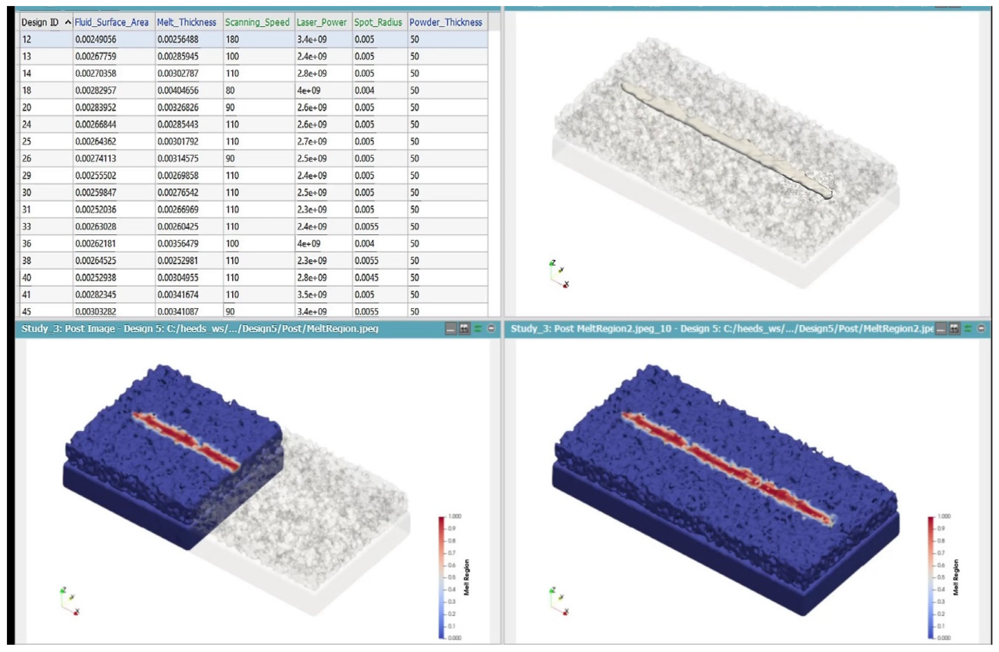
  • HEEDS software was used to optimize the inputs for FLOW-3D WELD simulation within the parameter ranges specified in Table 5.
Additionally, the scanning strategy was set as unidirectional and cross-scanning.
The optimization of the LPBF process was conducted using HEEDS, a design exploration platform that incorporates the SHERPA (Simultaneous Hybrid Exploration that is Robust, Progressive, and Adaptive) algorithm. SHERPA is a hybrid, adaptive search method that dynamically blends global and local optimization strategies, allowing for efficient navigation of complex, nonlinear, and high-dimensional parameter spaces.
Within the scope of this study, SHERPA was utilized to identify a parameter set that ensures melt pool stability and strengthens the mechanical integrity of the printed material. HEEDS systematically varied the input parameters within predefined bounds and executed a series of high-fidelity simulations. From these simulations, key performance indicators—including melt pool volume, surface area, and micro-porosity—were derived and assessed based on the defined optimization objectives. The primary aim was to maximize melt pool volume while simultaneously minimizing surface area and porosity, thereby achieving a structurally optimized and defect-suppressed final component. This data-driven optimization approach reduced dependency on conventional trial-and-error methods and enabled a more systematic, reliable tuning of process parameters.
This study utilized a 10 µm mesh resolution in the FLOW-3D WELD simulation, enhancing the accuracy of the simulations.

3. Results and Discussion

3.1. Powder Distribution and Packing Density

One of the critical factors for the success of the additive manufacturing process is the homogeneous distribution of the powder bed and the packing density. The additive manufacturing process flow diagram presented in Figure 3 encompasses the stages from the formation of the powder bed to the development of the molten pool. The uniformity of powder distribution directly influences material homogeneity and the quality of the final structure, playing a pivotal role in mechanical performance.
DEM simulations have shown that the irregular packing density in the powder bed significantly affects thermal behavior. It has been observed that smaller particles settle between larger particles, forming a denser structure, which increases packing density and improves thermal conductivity. The increase in packing density contributes to a more homogeneous energy distribution during laser interaction, resulting in a more balanced melting process. The simulated powder bed structure is shown in Figure 4.
Density variations in the powder bed can affect heat absorption during laser interaction and the consistency of the melting process, potentially leading to the formation of microstructural defects in the final structure. Particularly in areas with high density differences, heat transfer occurs at varying rates, resulting in issues such as incomplete melting or excessive melting in certain regions. This situation is a critical factor, especially regarding mechanical strength and material homogeneity, as it directly impacts the structural integrity of the component.

3.2. Melt Pool Formation and Thermal Behavior

HEEDS-based simulations have thoroughly revealed the effects of laser power, laser spot diameter, layer thickness, and scan speed on the geometric and thermal characteristics of the melt pool. The simulation results show that increasing laser power enhances the depth of the melt pool, contributing to complete material melting; however, beyond a certain threshold, irregularities are observed. One such irregularity is keyhole formation, which arises due to an imbalance in the vapor pressure within the melt pool, leading to defects such as micro-porosity in the final structure.
On the other hand, excessively high scan speeds result in insufficient laser energy transfer to the material, causing irregularities within the melt pool. Incorrect selection of laser parameters can lead to melt pool instability and weaken inter-layer bonding.

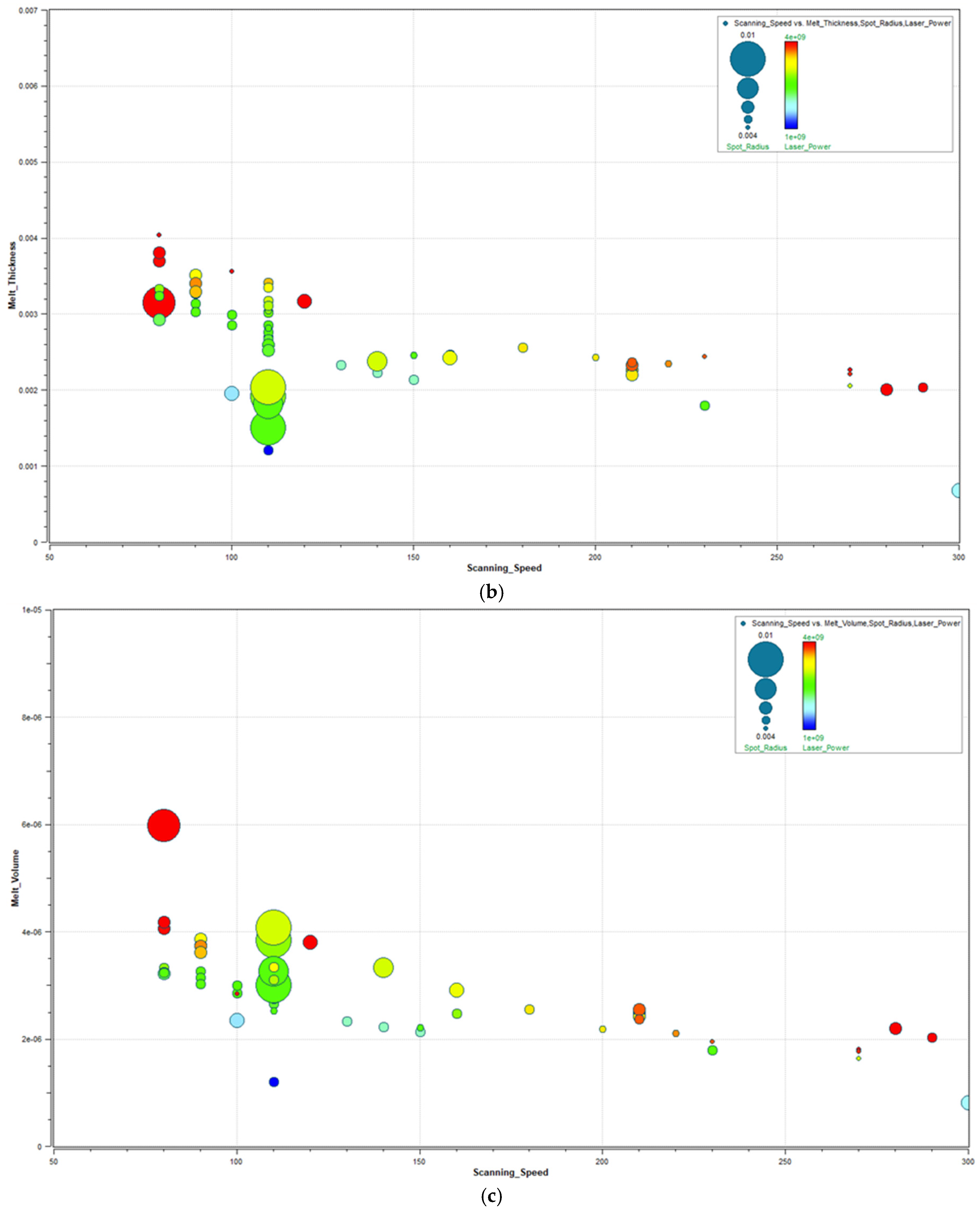
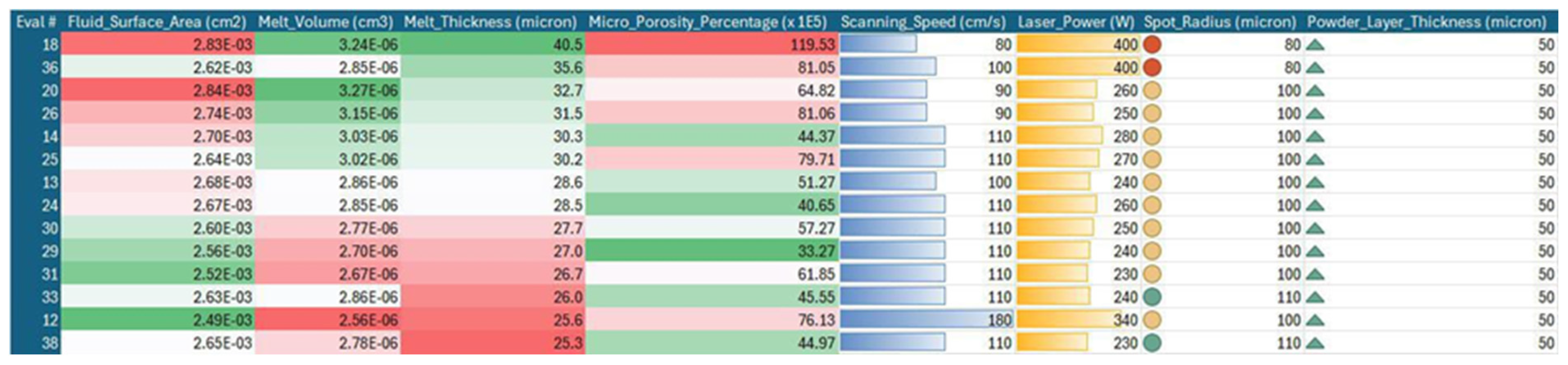
3.3. Optimization Results

Figure 5a–d presents the data obtained from 247 simulations conducted by varying scanning speed, spot radius, layer thickness (50 µm), and laser power. Within this analysis, critical parameters such as flow surface area, melt depth, melt volume, micro-porosity percentage, and laser absorption level (80%) were examined in detail. The simulation software represents dimensions such as track width as radius in graphical outputs. However, in this study, descriptions are provided in terms of diameter. This is because the input parameters for the SLM machine are defined in diameter.
In SLM simulations (Figure 5a), reducing the scanning speed increases the interaction time between the laser and the powder bed, leading to a higher energy input per unit length. This results in the formation of a larger melt pool surface area. As the applied laser power increases, this effect becomes more pronounced, causing more material to melt. On the other hand, increasing the laser spot diameter distributes energy over a wider area, reducing energy density and thereby limiting the expansion of the melt pool surface area. The maximum fluid surface area is observed under conditions of low scanning speed, high laser power, and a small spot diameter.
In LPBF simulations (Figure 5b), a decrease in scan speed increases the interaction time between the laser beam and the powder bed, leading to a higher energy input per unit length. This increased energy input results in the formation of a deeper melt pool, which in turn causes an increase in melt pool thickness. This effect becomes more pronounced with higher laser powers, which provide additional thermal energy. On the other hand, an increase in laser spot diameter causes the energy to spread over a wider area, reducing energy density and potentially leading to a larger but shallower melt pool. Therefore, under conditions of low scan speed, high laser power, and small spot diameter, the melt pool thickness reaches its maximum, while the opposite conditions result in the formation of thinner melt layers.
In LPBF simulations (Figure 5c), reducing the scan speed increases the energy input per unit length, leading to a larger amount of material melting. This effect becomes more pronounced with higher laser power, which provides additional thermal energy, resulting in deeper and wider melt pools. However, increasing the laser spot diameter causes the laser energy to spread over a larger area, reducing energy density, which may limit the melt volume. Therefore, the maximum melt volume is achieved under conditions of low scan speed, high laser power, and small spot diameter.
In LPBF simulations (Figure 5d), reducing the scan speed increases the energy input per unit length, which may promote full melting and contribute to a reduction in micro porosity. However, when excessively low scan speeds combine with high laser power, vaporization and keyhole instabilities can occur, leading to gas entrapment and an increase in porosity. Larger laser spot diameters reduce energy density, resulting in insufficient melting and consequently higher micro porosity formation. In contrast, smaller spot diameters focus the energy more intensively, enhancing melt homogeneity and reducing porosity. Therefore, minimizing micro porosity requires an optimized combination of scan speed, laser power, and spot diameter.
When multiple objectives are defined in the optimization process, the interactions between parameters must be carefully evaluated. As a result of the analysis, the optimal parameter combination was found in design 29. This design provides significant improvements in surface area and micro-porosity; although it does not achieve the targeted value for melt pool depth, it was determined to be the most efficient design overall. These results demonstrate that the careful selection of process parameters directly affects the final material properties in additive manufacturing processes. The HEEDS optimization algorithm, based on the conducted analyses, identified the optimal 14 parameter combinations, which are presented in Figure 6. During the optimization process, process parameters that minimize porosity while enabling the formation of a stable and homogeneous melt pool were determined. The simulations conducted allowed for a detailed analysis of the effects of parameters such as laser power, scan speed, laser spot diameter, and layer thickness on melt pool formation.
The optimized process parameters create a stable melt pool (achieving both a balanced depth-to-width ratio and enabling a homogeneous temperature distribution), thereby minimizing porosity and enhancing the structural integrity of the component. As a result, higher mechanical strength, improved fatigue life, and more predictable quality control during the manufacturing process are achieved. In this context, careful selection of laser parameters ensures that the production process progresses efficiently and without errors.
The detailed comparison of the 14 best-performing designs revealed that Design 29 achieved a 38% higher melt pool volume and a 42% reduction in micro-porosity compared to the baseline. Specifically, when laser power was set at 350 W, scanning speed at 120 mm/s, spot diameter at 50 µm, and layer thickness at 50 µm, the resulting melt pool volume was 5.8 × 10⁻³ mm3, and the porosity dropped below 0.8%. These quantitative results confirm that optimal combinations not only improve melt pool stability but also directly influence the structural density and mechanical performance of the part.
Simulations conducted during the optimization process resulted in up to 80% laser absorption, a 60% reduction in micro-porosity, and over a 30% improvement in melt pool volume and surface area. By detailing the effects of laser parameters on melt pool size, cooling rates, and solidification mechanisms, the simulations underscored the critical importance of process control. These findings demonstrate that optimizing process parameters in additive manufacturing significantly influences both microstructural and macrostructural properties. With the right parameter combinations, it is possible to control the manufacturing process to produce more durable, defect-free, and high-performance components.
Furthermore, the results emphasize the significance of optimizing single-track formation in SLM processes. However, to gain a more comprehensive understanding of the laser melting behavior, future studies are encouraged to focus on the following areas:
  • Investigation of different material alloys;
  • Experimental validation: Conducting tests with the same parameters in actual production environments will enhance the reliability of the simulation results;
  • Integration of machine learning: Employing machine learning algorithms to analyze large datasets can expedite the identification of optimal parameter combinations;
  • Impact of single-track formation on microstructure: Future research should explore how single-track formation affects microstructural evolution.
In the context of accelerating industrial-scale production, improving quality standards, and reducing manufacturing costs, the optimization of single-track formation is expected to become increasingly vital in future research efforts.

4. Conclusions

This study demonstrates the significant potential of process parameter optimization through an integrated DEM-CFD-based modeling approach and adaptive algorithms like HEEDS-SHERPA in enhancing the manufacturability of pure molybdenum using the LPBF method. The findings contribute valuable insights to digital design for manufacturing efforts in the additive manufacturing of refractory metals.
Simulation results revealed a laser absorption rate of up to 80%, a 60% reduction in micro-porosity, and more than a 30% improvement in melt pool volume and surface area. The optimal combination of parameters was found to be 350 W laser power, 120 mm/s scanning speed, 50 µm spot diameter, and 50 µm layer thickness, which led to enhanced melt pool stability and minimized porosity. Additionally, the study highlighted the impact of powder bed packing density and particle distribution on melt pool stability, demonstrating how precise control of laser parameters can significantly improve production quality by preventing defects such as incomplete melting, excessive heat accumulation, and keyhole formation.
In this context, the study underscores the crucial role of parameter optimization in achieving mechanical integrity, low porosity, and a homogeneous microstructure, with a focus on single-track formation. These findings provide an important foundation for the reliable production of molybdenum-based components in additive manufacturing processes for high-performance applications, such as those in aerospace and energy sectors.

Author Contributions

İ.B.T. contributed to the preparation and organization of the manuscript, provided input into the interpretation of results, and wrote the final version of the paper. N.D. was responsible for the development of the methodological design, performed the literature review, wrote the initial draft of the manuscript, conducted numerical simulations, and contributed to the interpretation of the results. M.U.S. was responsible for the overall organization of the study, coordination of simulation processes, played a key role in decision-making throughout the study, and contributed to the interpretation of the results. All authors have read and agreed to the published version of the manuscript.

Funding

This research was financially supported by the Scientific and Technological Research Council of Türkiye (TUBITAK) under project no. 20AG008.

Institutional Review Board Statement

Not applicable.

Informed Consent Statement

Not applicable.

Data Availability Statement

The data presented in this study are available in the article.

Acknowledgments

We would like to express our sincere gratitude to the following organizations for their valuable contributions to this study. Special thanks to IOG Engineering for their software support, Onatus Vision Technologies Turkey for providing the temperature-dependent physical and thermal properties of molybdenum, and Nanografi for supplying the molybdenum powder properties. The authors also thank The Scientific and Technological Research Council of Türkiye (TUBITAK) for the financial support under project no. 20AG008.

Conflicts of Interest

The authors declare that there is no conflict of interest regarding the content of this manuscript.

References

  1. Dimiduk, D.M.; Perepezko, J.H. Mo–Si–B alloys: Developing a revolutionary turbine-engine material. MRS Bull. 2003, 28, 639–645. [Google Scholar] [CrossRef]
  2. Faidel, D.; Jonas, D.; Natour, G.; Behr, W. Investigation of the selective laser melting process with molybdenum powder. Addit. Manuf. 2015, 8, 88–94. [Google Scholar] [CrossRef]
  3. Yan, A.; Atif, A.M.; Wang, X.; Lan, T.; Wang, Z. The microstructure and cracking behaviors of pure molybdenum fabricated by selective laser melting. Materials 2021, 15, 6230. [Google Scholar] [CrossRef]
  4. Gu, D.D.; Meiners, W.; Wissenbach, K.; Poprawe, R. Laser additive manufacturing of metallic components: Materials, processes and mechanisms. Int. Mater. Rev. 2012, 57, 133–164. [Google Scholar] [CrossRef]
  5. Maamoun, A.H.; Xue, Y.F.; Elbestawi, M.A.; Veldhuis, S.C. Effect of selective laser melting process parameters on the quality of Al alloy parts: Powder characterization, density, surface roughness, and dimensional accuracy. Materials 2018, 11, 2343. [Google Scholar] [CrossRef] [PubMed]
  6. Braun, J.; Kaserer, L.; Stajkovic, J.; Leitz, K.-H.; Tabernig, B.; Singer, P.; Leibenguth, P.; Gspan, C.; Kestler, H.; Leichtfried, G. Molybdenum and tungsten manufactured by selective laser melting: Analysis of defect structure and solidification mechanisms. Int. J. Refract. Met. Hard Mater. 2019, 84, 104999. [Google Scholar] [CrossRef]
  7. Wang, D.; Yu, C.; Ma, J.; Liu, W.; Shen, Z. Densification and crack suppression in selective laser melting of pure molybdenum. Mater. Des. 2017, 129, 44–52. [Google Scholar] [CrossRef]
  8. Zhou, X.; Liu, X.; Zhang, D.; Shen, Z.; Liu, W. Balling phenomena in selective laser melted tungsten. J. Mech. Work. Technol. 2015, 222, 33–42. [Google Scholar] [CrossRef]
  9. Leung, C.L.A.; Marussi, S.; Towrie, M.; Atwood, R.C.; Withers, P.J.; Lee, P.D. The effect of powder oxidation on defect formation in laser additive manufacturing. Acta Mater. 2019, 166, 294–305. [Google Scholar] [CrossRef]
  10. Li, K.; Wang, D.; Xing, L.; Wang, Y.; Yu, C.; Chen, J.; Zhang, T.; Ma, J.; Liu, W.; Shen, Z. Crack suppression in additively manufactured tungsten by introducing secondary-phase nanoparticles into the matrix. Int. J. Refract. Met. Hard Mater. 2019, 79, 158–163. [Google Scholar] [CrossRef]
  11. Kaserer, L.; Braun, J.; Stajkovic, J.; Leitz, K.-H.; Tabernig, B.; Singer, P.; Letofsky-Papst, I.; Kestler, H.; Leichtfried, G. Fully dense and crack free molybdenum manufactured by Selective Laser Melting through alloying with carbon. Int. J. Refract. Met. Hard Mater. 2019, 84, 105000. [Google Scholar] [CrossRef]
  12. Tan, C.; Zhou, K.; Ma, W.; Attard, B.; Zhang, P.; Kuang, T. Selective laser melting of high-performance pure tungsten: Parameter design, densification behavior and mechanical properties. Sci. Technol. Adv. Mater. 2018, 19, 370–380. [Google Scholar] [CrossRef]
  13. Huang, G.; He, Y.; Long, S.; Duan, Q.; Chen, H.; Peng, X.; Zhou, L.; Huang, K. Microstructure, compressive performance and wear resistance of pure molybdenum additively manufactured via laser powder bed fusion. Int. J. Refract. Met. Hard Mater. 2024, 123, 106740. [Google Scholar] [CrossRef]
  14. Rebesan, P.; Ballan, M.; Bonesso, M.; Campagnolo, A.; Corradetti, S.; Dima, R.; Gennari, C.; Longo, G.; Mancin, S.; Manzolaro, M.; et al. Pure molybdenum manufactured by Laser Powder Bed Fusion: Thermal and mechanical characterization at room and high temperature. Addit. Manuf. 2021, 47, 102277. [Google Scholar] [CrossRef]
  15. Yakang, K.; Wang, C.; Chen, X.; Qu, Y.; Yu, J.; Ju, H.; Yilei, X. Review of Research Progress on Mo–Si–B Alloys. Materials 2023, 16, 5495. [Google Scholar] [CrossRef] [PubMed]
  16. Makineni, S.; Kini, A.; Jägle, E.; Springer, H.; Raabe, D.; Gault, B. Synthesis and stabilization of a new phase regime in a Mo–Si–B based alloy by laser-based additive manufacturing. Acta Mater. 2018, 151, 31–40. [Google Scholar] [CrossRef]
  17. Chen, X.; Kong, Y.; Qu, Y.; Yu, J.; Xiao, Y.; Wang, C. Influence of TiC contents on the microstructure, mechanical properties, and oxidation behavior of Mo–10Si–8B alloys. Intermetallics 2024, 164, 108122. [Google Scholar] [CrossRef]
  18. Guo, Z.; Wang, L.; Wang, C.; Ding, X.; Liu, J. Heat transfer, molten pool flow micro-simulation, and experimental research on molybdenum alloys fabricated via selective laser melting. Materials 2021, 14, 75. [Google Scholar] [CrossRef] [PubMed]
  19. Wu, Y.; Li, M.; Wang, J.; Wang, Y.; An, X.; Fu, H.; Zhang, H.; Yang, X.; Zou, Q. Powder-bed-fusion additive manufacturing of molybdenum: Process simulation, optimization, and property prediction. Addit. Manuf. 2022, 58, 103069. [Google Scholar] [CrossRef]
  20. Khairallah, S.A.; Anderson, A.T.; Rubenchik, A.; King, W.E. Laser powder-bed fusion additive manufacturing: Physics of complex melt flow and formation mechanisms of pores, spatter, and denudation zones. Acta Mater. 2016, 108, 36–45. [Google Scholar] [CrossRef]
  21. King, W.E.; Anderson, A.T.; Ferencz, R.M.; Hodge, N.E.; Kamath, C.; Khairallah, S.A.; Rubenchik, A.M. Laser powder bed fusion additive manufacturing of metals; physics, computational, and materials challenges. Appl. Phys. Rev. 2015, 2, 041304. [Google Scholar] [CrossRef]
  22. Chen, H.-Y.; Lin, C.-C.; Horng, M.-H.; Chang, L.-K.; Hsu, J.-H.; Chang, T.-W.; Hung, J.-C.; Lee, R.-M.; Tsai, M.-C. Deep learning applied to defect detection in powder spreading process of magnetic material additive manufacturing. Materials 2022, 15, 5662. [Google Scholar] [CrossRef] [PubMed]
Figure 1. Particle size distribution graph.
Applsci 15 05485 g001
Figure 2. (a). Temperature-dependent density (Kelvin, g/cm3) (b). Temperature-dependent viscosity (Kelvin, g/cm·s) (c). Temperature-dependent specific heat (Kelvin, 10−7 J/g·K) (d). Temperature-dependent thermal conductivity (Kelvin, 10−7 W/cm·K).
Applsci 15 05485 g002
Figure 3. LPBF simulation process: step-by-step illustration from powder spreading to melt pool formation.
Applsci 15 05485 g003
Figure 4. Simulation results illustrating the melt track geometry obtained under specific processing parameters and the corresponding temperature distribution.
Applsci 15 05485 g004
Figure 5. (ad) Results obtained from 247 simulations conducted with a 10 µm mesh size.
Applsci 15 05485 g005aApplsci 15 05485 g005bApplsci 15 05485 g005c
Figure 6. The best 14 parameters obtained from the optimization results.
Applsci 15 05485 g006
Table 1. Physical properties of molybdenum.
ItemResult
Melting Point2610 °C
Boiling Point5560 °C
Crystal StructureBody-Centered Cubic (BCC)
Density8.2 g/cm3
Coefficient of Expansion @ 20 °C5.1 × 10⁻6/°C
Electrical Resistivity5.17 µΩ·cm
FormPowder
Table 2. Boundary values of particle size groups.
Particle Diameter (µ)Value
Dmin15
D1024.34
D5033.26
D9044.6
Dmax45
Table 3. Particle sizes and volumetric ratios of the group.
Group Particle Diameter (µ)Volume Percentage (%)
19.6710
28.840
38.9340
44.810
Table 4. Group particle sizes and numerical ratios are defined for the CFD.
Particle Radius (µm)Particle Number Density Percentage (%)
9.83534.78
14.444.33
19.46517.95
22.42.94
Table 5. Input parameters and boundary values defined for HEEDS software.
ParameterMinBaselineMax
Scanning Speed (mm/s)80150300
Laser Power (W)50200400
Laser Spot Diameter (µm)4050100
Powder Layer Thickness (µm)5050100
Disclaimer/Publisher’s Note: The statements, opinions and data contained in all publications are solely those of the individual author(s) and contributor(s) and not of MDPI and/or the editor(s). MDPI and/or the editor(s) disclaim responsibility for any injury to people or property resulting from any ideas, methods, instructions or products referred to in the content.

