Article

Research on Key Parameters and Engineering Experiments of Coal Gangue Slurry Filling Technology

1
School of Energy and Mining Engineering, China University of Mining & Technology-Beijing, Beijing 100083, China
2
School of Energy Engineering, Xi’an University of Science and Technology, Xi’an 710054, China
*
Authors to whom correspondence should be addressed.
Appl. Sci. 2025, 15(10), 5475; https://doi.org/10.3390/app15105475
Submission received: 14 April 2025 / Revised: 10 May 2025 / Accepted: 12 May 2025 / Published: 13 May 2025

Abstract

:
In this paper, a gangue grouting filling technology in goafs is proposed based on the dual requirements of not affecting the average production of tens of millions of tons of coal from mines and achieving the large-scale underground disposal of coal gangue, and the technology’s principle and critical technical issues are elucidated. This article explores practical problems, such as how coal gangue forms slurry, how the long-distance pipeline transportation of coal gangue slurry can be realized, and how coal gangue slurry intervenes in the gaps of collapsed rocks in goafs through laboratory experiments and large-scale experiments. Finally, the feasibility of this technology was verified through on-site underground industrial experiments to explore a technically and economically feasible avenue for the underground filling of coal gangue in tens of millions of tons of coal from mines in western China.

1. Introduction

As China’s primary energy source and an essential chemical raw material, coal plays a fundamental and primary role as a “ballast” and “regulator” in ensuring energy security [1,2]. However, in the process of coal resource development, about 10~20% of coal gangue needs to be discharged, which inevitably causes environmental pollution and ecological damage in the mining area [3,4]. The Chinese government and various provincial and municipal governments have introduced a series of policies and regulations to improve the comprehensive utilization rate of coal gangue. However, the total utilization rate of coal gangue is still not high, and coal gangue accumulated over the years has not been effectively treated. The green disposal of coal gangue has become one of the problems affecting coal resource extraction and ecological environmental protection in China [5,6]. Therefore, how to achieve the efficient removal of coal gangue while safeguarding “green mountains and clear waters” is a significant development challenge faced by coal enterprises [7,8].
Long-term theoretical research and practice in China have proven that underground filling in coal mines is an essential technical approach for the disposal and utilization of coal gangue. The underground filling technology of coal gangue has a development history of several decades in China [9,10,11,12]. It has come in the form of three underground filling technologies for different needs in different periods, including roadway dumping filling, solid filling of working faces, paste filling of working faces, short-wall cementation filling, and grouting filling of overlying strata. These coal gangue filling technologies have been successfully applied in dozens of mining areas and hundreds of pairs of mines in China. They have achieved various goals, such as the green discharge of coal gangue and the safe recovery of coal resources [13,14,15,16,17,18]. However, the existing underground filling technology of coal gangue has the problem of spatiotemporal interference between coal mining and filling, which seriously restricts the efficient extraction of coal and the large-scale filling of coal gangue. In terms of the solid filling and paste filling technology of working faces, coal mining and filling are carried out in the same space successively. After mining 1~3 coal knives, filling is carried out once, and then upon continuing to mine 1~3 coal knives, filling is carried out again. This process is repeated until the entire working face is fully filled. In addition, it is not easy to arrange a filling working face specifically for handling coal gangue in a high-yield and efficient mine with a capacity of tens of millions of tons [19,20,21,22]. For roadway dumping filling and short-wall cementation filling, the speed of coal excavation in the roadway limits the filling efficiency, making it difficult for the coal mining and filling capacity to exceed 500,000 tons/year [23]. For the grouting filling of overlying strata, it is necessary to drill grouting holes on the ground in advance before the mining face, and the timing of the grouting filling is directly related to the migration law of the overlying strata in the mining site [24,25].
The mining of coal resources in China has gradually shifted westward, and the tens of millions of tons of coal obtained from mines in the western regions are also facing the problem of the large-scale green disposal of coal gangue. However, existing underground filling technology cannot meet the high production and efficient operation of mines while achieving underground disposal of coal gangue. Therefore, this article proposes a gangue grouting filling technology in goafs, elucidates the principle and key technical issues of the technology, and gradually explores practical problems such as how coal gangue forms slurry, how the long-distance pipeline transportation of coal gangue slurry can be realized, and how coal gangue slurry intervenes in the gaps of collapsed rocks in goafs through laboratory experiments and large-scale experiments. Finally, the feasibility of this technology was verified through on-site underground industrial experiments, with the aim of exploring a technically and economically feasible avenue for the underground filling of coal gangue in tens of millions of tons of coal from mines in western China.

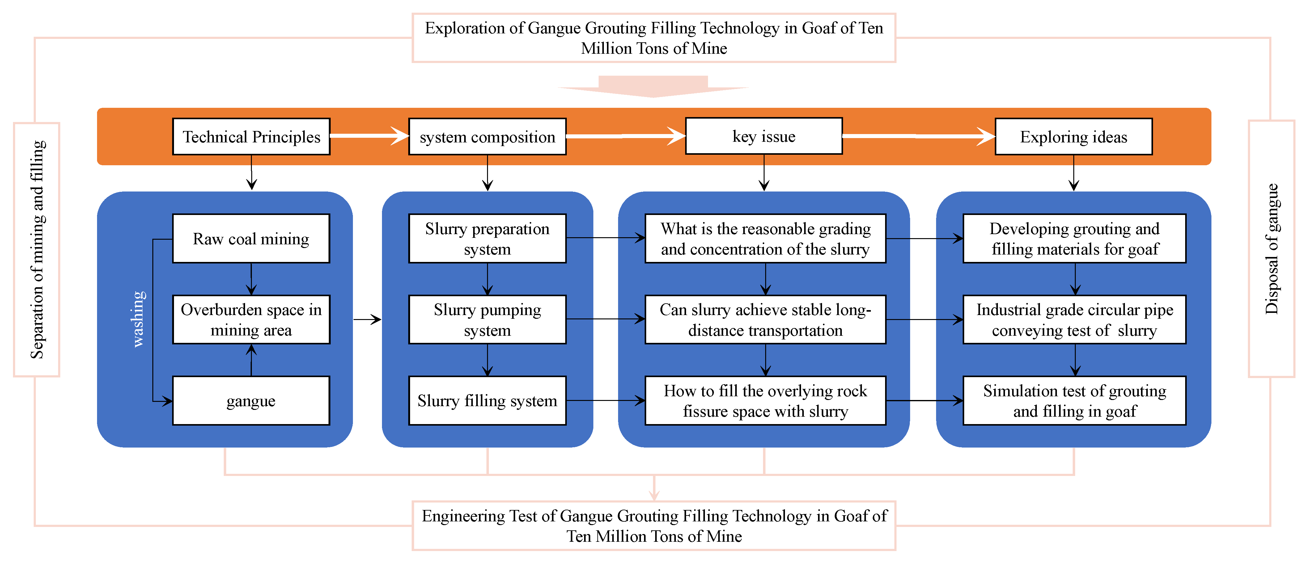
2. Gangue Grouting Filling Technology in Goafs

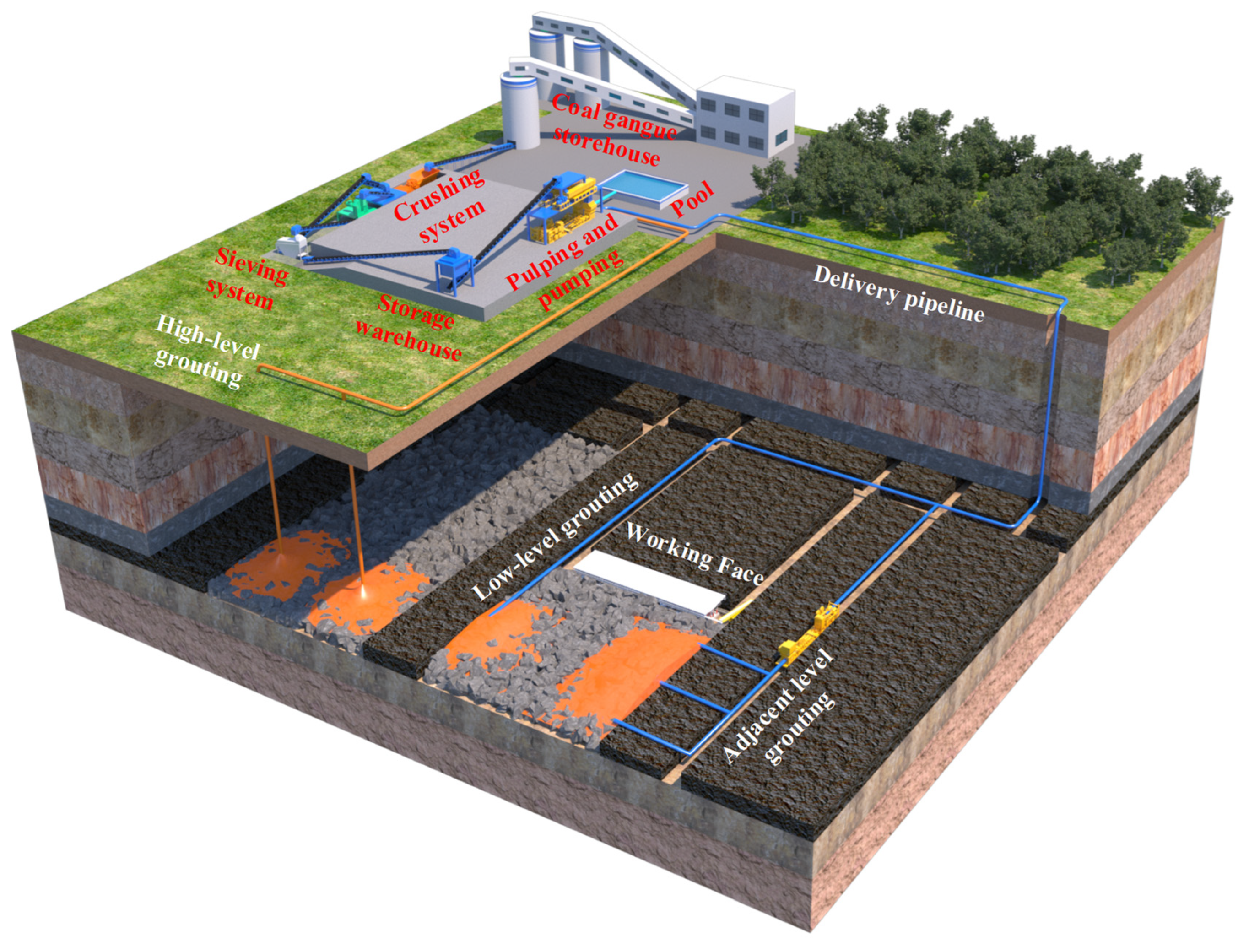
2.1. Principle and System Composition of Gangue Grouting Filling Technology in Goafs

Based on the dual needs of not affecting the average production of tens of millions of tons of coal from mines and achieving the large-scale underground disposal of coal gangue, the concept of “fluidized filling” is proposed, which means that the coal gangue is made into a coal gangue slurry and filled into the gaps and fissure spaces in the collapse zone, fissure zone, and separation zone of goafs.
Gangue grouting filling technology in a goaf involves breaking or grinding coal gangue into particle aggregates with a specific particle size distribution, mixing them with water in a proportion to produce a particular concentration of gangue slurry, and then using a grouting pump to fill the gangue slurry into the overlying rock fissure space in the goaf through pipeline transportation. Ultimately, the large-scale underground disposal of coal gangue is achieved without affecting the average production of the coal mine, as shown in Figure 1. Gangue grouting filling technology in a goaf includes a slurry preparation system, a slurry pumping system, and a slurry filling system. The slurry preparation system uses technical means such as crushing, screening, or grinding to form the raw coal gangue into a particle aggregate with a particular particle size distribution and then forms a specific concentration of gangue slurry in a mixer with water in a certain proportion; the slurry pumping system is used to pressurize the gangue slurry using a grouting pump or gravity flow, and the slurry is then transported to the target area underground or on the ground through pipeline transportation; the grouting filling system is used to fill the gangue slurry in the target area into the gaps and fissure spaces in the collapse zone, fissure zone, or separation zone using one or more methods of low-level grouting, adjacent-level grouting, or high-level grouting.

2.2. Technical Difficulties and Solutions of Gangue Grouting Filling in Goafs

Based on the principle and system composition of gangue grouting filling technology in goafs, the reasonable grading and concentration of the slurry, whether the slurry can be stably transported over a long distance, and how the slurry fills the overlying rock fissure space are three key questions that need to be answered by this technology, as shown in Figure 2.
Laboratory testing and research regarding the reasonable grading and concentration of the slurry were conducted, the water permeability and slump of coal gangue slurry under different gradations and attention levels were analyzed, and grouting and filling materials for goafs were developed. The industrial-grade circular pipe transportation performance of coal gangue slurry was researched to determine the stability and feasibility of the long-distance transportation of coal gangue slurry. The relationship between the reasonable grading and specific concentration of coal gangue slurry and its pumping flow rate and transportation resistance were analyzed, and the stability and feasibility of the long-distance transportation of coal gangue slurry was determined. We conducted simulation experiments on how to fill the overlying rock fissure space with slurry, studied the flow and diffusion laws of coal gangue slurry in the gaps between collapsed rock blocks under reasonable grading and specific concentrations, and determined the feasibility of using coal gangue slurry to intervene in goafs.

3. Research and Development of Millimeter-Grade Gangue Grouting Filling Material

The research and development of gangue grouting materials is the foundation of coal gangue grouting filling technology in goafs. It is necessary to determine a reasonable gangue grading and appropriate slurry concentration and to fully consider issues such as the gangue particle size composition and crushing and screening costs. Therefore, based on the difficulty in and high price of controlling the grading of different particle sizes of gangue within a reasonable range, this technology changed the gangue particle size grading by limiting the upper limit of the gangue particle size and then conducted bleeding rate and slump experiments with different gangue slurry concentrations, ultimately determining the preliminary parameters of the millimeter-grade gangue grouting filling materials. The gangue used in this investigation was the original crushed gangue sample, and the particle size distribution of the gangue is shown in Table 1.

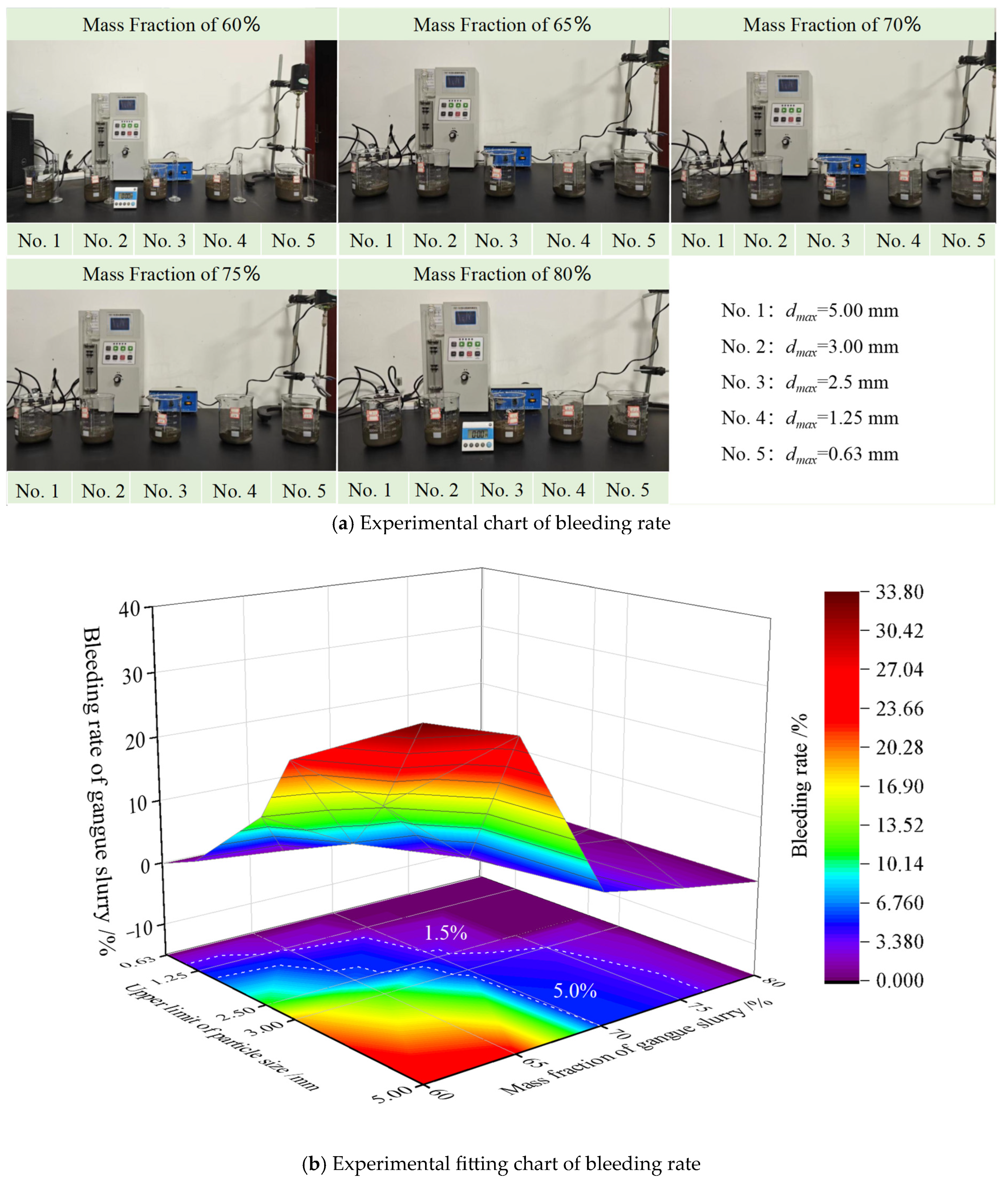
3.1. The Bleeding Performance of Different Gangue Grades and Slurry Concentrations

Based on the physical significance of the concrete bleeding rate, the bleeding rate of the gangue slurry was used to characterize the water retention properties of different gangue grades and slurry concentrations. Then, a reasonable range of the slurry concentration was determined. The bleeding rate of gangue slurry refers to the ratio of water secreted from the gangue slurry to the total amount of water in the gangue slurry. The formula for calculating the bleeding rate of the slurry is as follows:
B m = m m m 0 + m 1 ω
In the above formula, Bm is the bleeding rate of the gangue slurry, %; mm is the total amount of bleeding in the slurry, g; m0 is the total amount of water added during the preparation of the slurry, g; m1 is the amount of gangue added during the preparation of the slurry, g; and ɷ is the moisture content in the gangue, %.
The upper limits of the gangue particle size controlled in this experiment were −5 mm, −3 mm, −2.5 mm, −1.25 mm, and −0.63 mm, respectively. The slurry concentrations were set to 60%, 65%, 70%, 75%, and 80%, respectively. A total of 25 sets of experiments were conducted, and the moisture content of the gangue under different gradations was measured before the experiment. The overall plan of this investigation was to keep the total amount of 200 g of gangue unchanged and to prepare 60%, 65%, 70%, 75%, and 80% gangue slurries by controlling the different water amounts in sequence. Then, the gangue slurry was allowed to stand still, and the water released from the surface of the gangue slurry was sucked out using a rubber-tipped dropper at different times. After 90 min, the mass of accumulated water released was calculated [26,27,28]. Finally, the bleeding rate of the gangue slurry was calculated according to Formula (1), and the data were processed, as shown in Table 2 and Figure 3.
Figure 3 shows three main aspects: (1) As the upper limit of the gangue particle size increased, the bleeding rate of the gangue slurry showed an upward trend. As the concentration of the gangue slurry increased, the bleeding rate of gangue slurry showed a downward trend, that is, the gangue particle size was inversely proportional to the water retention performance of the slurry, and the slurry concentration was directly proportional to the water retention performance of the slurry. (2) Based on the standard that the bleeding rate of qualified paste is between 1.5% and 5.0% [29], a reasonable gangue particle size grading and an appropriate gangue slurry concentration were a variable interval, and the gangue particle size grading and gangue slurry concentration interacted with each other. (3) From the perspective of the variable interval, there was a corresponding relationship between a reasonable gangue particle size grading and an appropriate slurry concentration. When the upper limit of the gangue particle size was 5 mm, the appropriate slurry concentration was 70.0–76.7%; when the upper limit of the gangue particle size was 3 mm, the appropriate slurry concentration was 69.1–74.9%; when the upper limit of the gangue particle size was 2.5 mm, the appropriate slurry concentration was 66.5–70.8%; when the upper limit of the gangue particle size was 1.25 mm, the appropriate slurry concentration was less than 63.5%; when the slurry concentration was 60%, the reasonable upper limit of the gangue particle size was 1.01–1.56 mm; and when the slurry concentration was 70%, the reasonable upper limit of the gangue particle size was 2.3–5.0 mm.

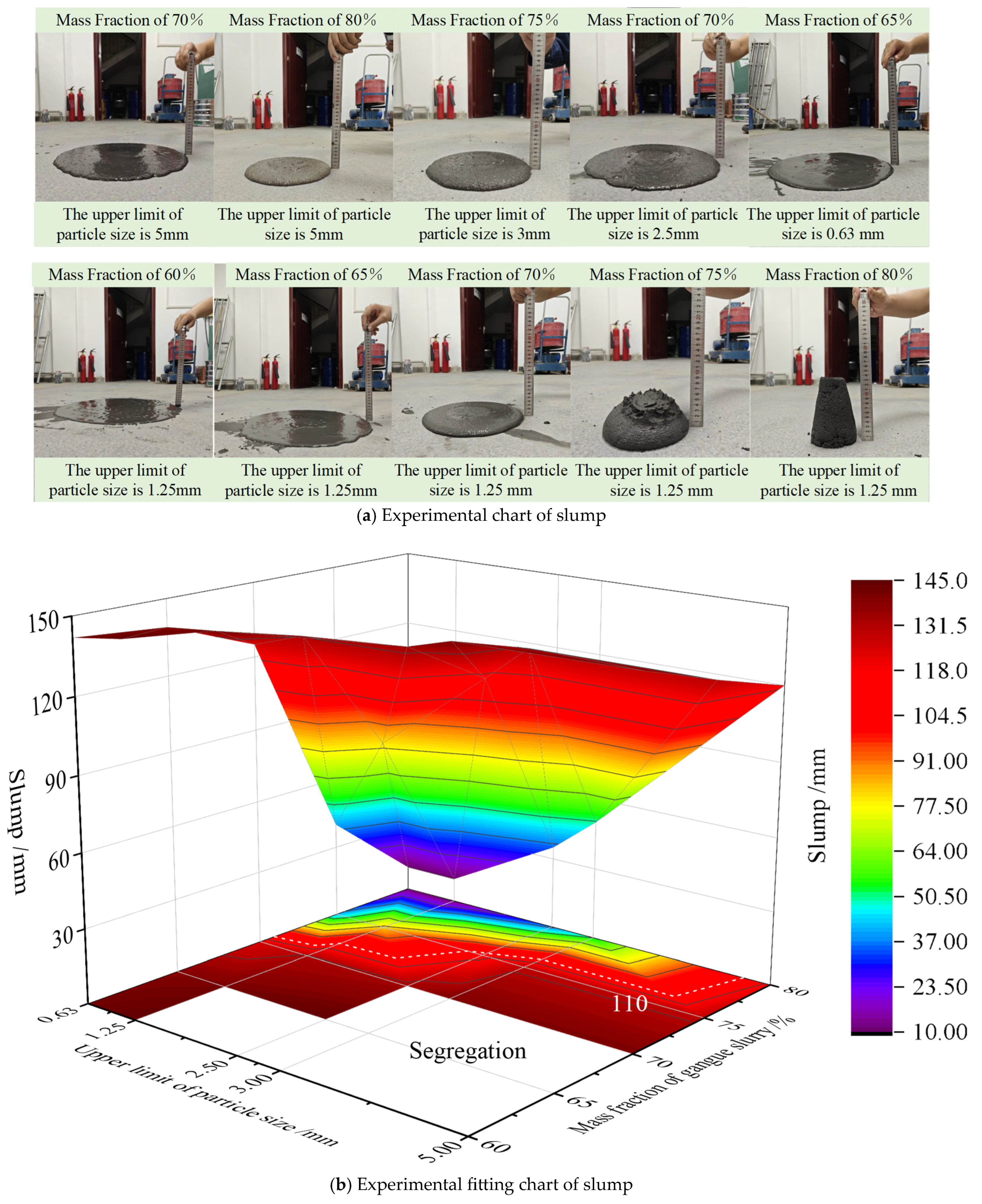
3.2. Collapse Performance of Different Gangue Grades and Slurry Concentrations

Slump refers to the difference between the height of the test bucket and the maximum height of the filled slurry after the collapse and is the simplest method to measure the flow performance of a slurry [30,31]. In this experiment, a standard slump cylinder with an upper diameter of 50 mm, a lower diameter of 100 mm, and a height of 150 mm was used to scale the slump of the different gangue grades and slurry concentrations. Twenty-five sets of slump data were measured, as shown in Table 3 and Figure 4.
Since gangue slurry is a super-fluidized paste, the slump value of a high-slump gangue slurry should be greater than 220 mm without segregation [32,33]. Therefore, considering the proportional scaling of the micro slump cylinder, the slump value of the high-slump gangue slurry in this experiment had to be higher than 110 mm.
From Figure 4, the following can be seen: (1) When the upper limit of the gangue particle size was more than 2.50 mm and the slurry concentration was below 65%, there was a risk of segregation or segregation in the gangue slurry; when the upper limit of the gangue particle size was less than 3.00 mm and the slurry concentration was above 75%, it was difficult to transport the gangue slurry. (2) As the gangue particle size upper limit increased, the gangue slurry slump showed an increasing trend. As the concentration of the gangue slurry increased, the slump of the gangue slurry showed a decreasing trend. The gangue particle size was directly proportional to the slurry transportation performance, while the slurry concentration was inversely proportional to the slurry transportation performance. (3) Within a specific range, a reasonable grading of the gangue particle size should correspond to an appropriate slurry concentration. When the upper limit of the gangue particle size was 5 mm, the appropriate slurry concentration was 70–80%; when the upper limit of the gangue particle size was 3 mm, the appropriate slurry concentration was 70–76.2%; when the upper limit of the gangue particle size was 2.5 mm, the appropriate slurry concentration was 65–75.3%; when the upper limit of the gangue particle size was 1.25 mm, the appropriate slurry concentration was 60–72%; and when the upper limit of the gangue particle size was 0.63 mm, the appropriate slurry concentration was 60–70.9%.

3.3. Preliminary Parameters of Millimeter-Grade Gangue Slurry

Based on the bleeding experiment and slump experiment of the gangue slurry and considering the stability and transportability of the gangue slurry, it is believed that a qualified gangue slurry is an organic combination of the gangue particle size grading and the slurry concentration. When the upper limit of the gangue particle size is 5 mm, the concentration of the gangue slurry should be controlled between 70.0% and 76.7%; when the upper limit of the gangue particle size is 3 mm, the concentration of the gangue slurry should be maintained between 70% and 74.9%; when the upper limit of the gangue particle size is 2.5 mm, the concentration of the gangue slurry should be controlled between 66.5% and 70.8%; when the upper limit of the gangue particle size is 1.25 mm, the concentration of the gangue slurry should be maintained between 60.0% and 63.5%.

4. Industrial-Grade Circular Pipe Conveying Test of Gangue Slurry

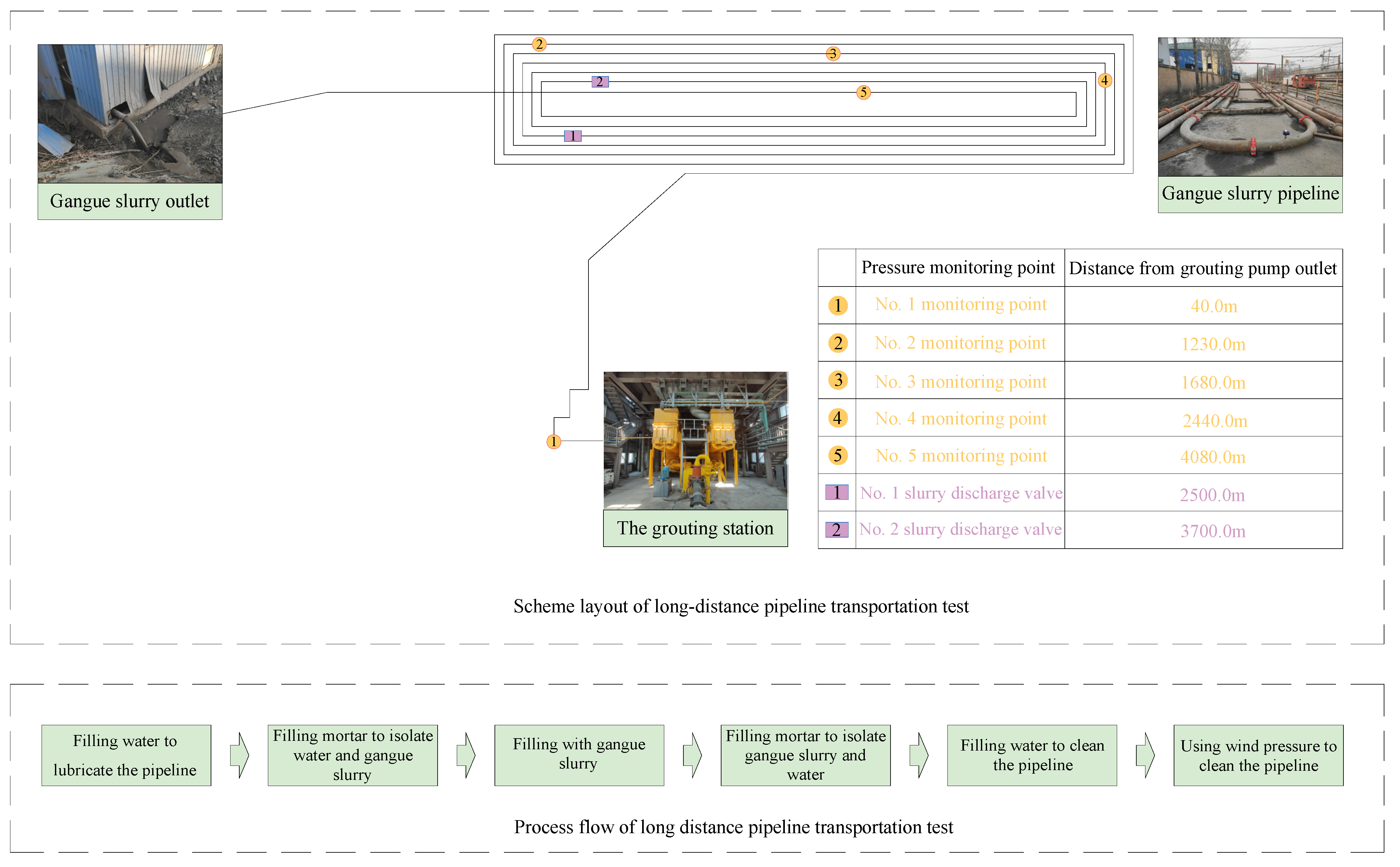
4.1. Scheme for Long-Distance Pipeline Transportation Test

The long-distance pipeline transportation test of gangue slurry carried out in this study was based on a paste filling station and a gangue mountain. Firstly, the ground paste filling station was used to mix the crushed coal gangue with water to produce a specific concentration of gangue slurry. Then, a pipeline of about 4500 m was arranged on the ground according to the terrain of the mining area. Finally, a grouting pump was used to transport the gangue slurry through the pipeline to the vicinity of the gangue mountain [34,35,36], as shown in Figure 5.

4.2. Design of Long-Distance Pipeline Transportation Test

4.2.1. Test Parameters of Long-Distance Pipeline Transportation

Based on the above primary experimental results, the mass fraction of the gangue slurry used in the long-distance pipeline transportation test was 71%. The crushed gangue particle size ranged from 1.25 to 5 mm, accounting for 32.33%, 0.075 to 1.25 mm, accounting for 40.67%, and less than 0.075 mm, accounting for 27.0%. In this experiment, the inner diameter of the pipeline was about 201 mm, and this was determined by changing the pumping flow rate of the gangue slurry at different periods, monitoring the pressure at different positions of the pipeline, analyzing the relationship between the transportation resistance and flow rate of the gangue slurry at specific concentrations, and determining the stability and feasibility of the long-distance transportation of the gangue slurry.

4.2.2. Process of Long-Distance Pipeline Transportation Test

The long-distance pipeline transportation test process was divided into six primary functions: pre-filling lubrication, mortar and water separation, grouting filling, mortar and gangue separation, post-filling pipe washing, and air pressure cleaning, as shown in Figure 5. The detailed processes were as follows.
Pre-filling lubrication pipe: a a grouting pump was used to pump 30 m3 of clean water into the pipeline, achieving the goal of wetting the pipeline and removing debris inside the pipeline. Mortar waterproofing: before the pumping of the 30 m3 of water was completed, 40 m3 of prepared mortar was pumped into the pipeline through a grouting pump to isolate the water from the gangue slurry. Grouting filling: Before the 40 m3 of slurry was pumped, the prepared gangue slurry was pumped into the pipeline using a grouting pump. When the slurry was seen at the end of the pipeline, the pressure at different positions of the pipeline was monitored by changing the pumping flow rate of the grouting pump. Mortar separation: before the pumping of the gangue slurry was completed, the prepared 20 m3 of mortar was pumped into the pipeline again using a grouting pump to isolate the gangue slurry from the water. After filling and washing the pipeline: Before the 20 m3 of mortar was pumped, the injection pump was used again to pump clean water into the pipeline. When the clean water was seen at the end of the pipeline, the pump was stopped from achieving the purpose of cleaning the pipeline. Pressure air cleaning: after the clean water was pumped, the pressurized air system was opened, and high-pressure airflow was used to blow out the remaining large particles of gangue from the pipeline, achieving the goal of removing sewage from the pipeline and thoroughly cleaning the pipeline.

4.2.3. Monitoring System for Long-Distance Pipeline Transportation Test

The test monitoring adopted a LORa wireless pressure transmitter, with five pressure monitoring points set up. Among them, the first pressure monitoring point was 40.00 m away from the outlet of the grouting pump, the second pressure monitoring point was 1230.0 m away from the outlet of the grouting pump, and there were ten 90-degree corners and two 135-degree corners between the first monitoring point and the second pressure monitoring point. The third pressure monitoring point was 1680.0 m away from the outlet of the grouting pump, and there were four 90-degree angles between it and the second monitoring point. The fourth pressure monitoring point was 2440 m away from the outlet of the grouting pump, and there were three 90-degree angles between it and the third monitoring point. The fifth pressure monitoring point was 4080.0 m away from the outlet of the grouting pump, and there were thirteen 90-degree angles between it and the fourth monitoring point. In addition, one discharge valve was arranged at a distance of 2500 m and 3700 m, respectively, from the outlet of the grouting pump to address the problem of pipeline blockage.

4.3. Experimental Analysis of Long-Distance Pipeline Transportation

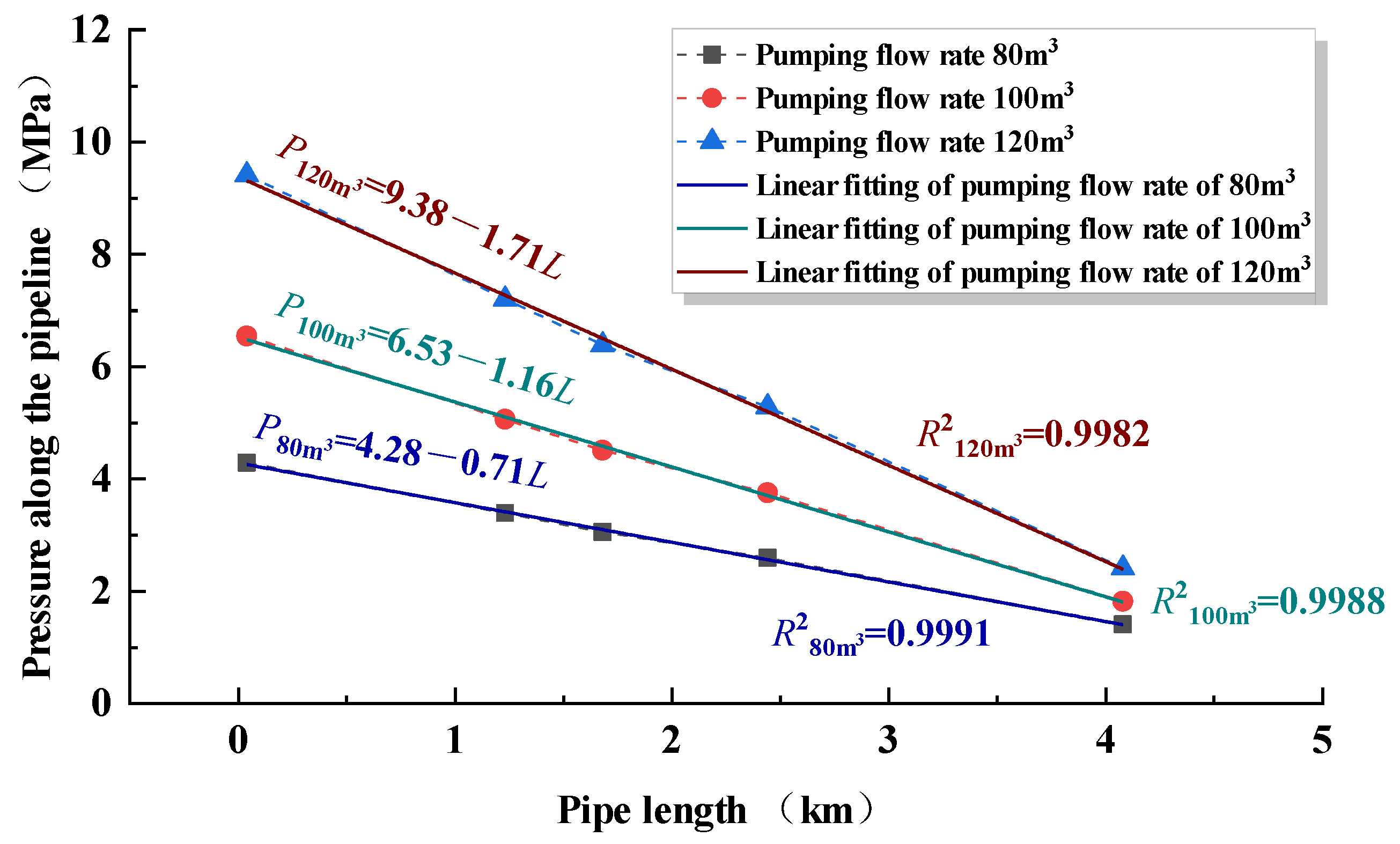
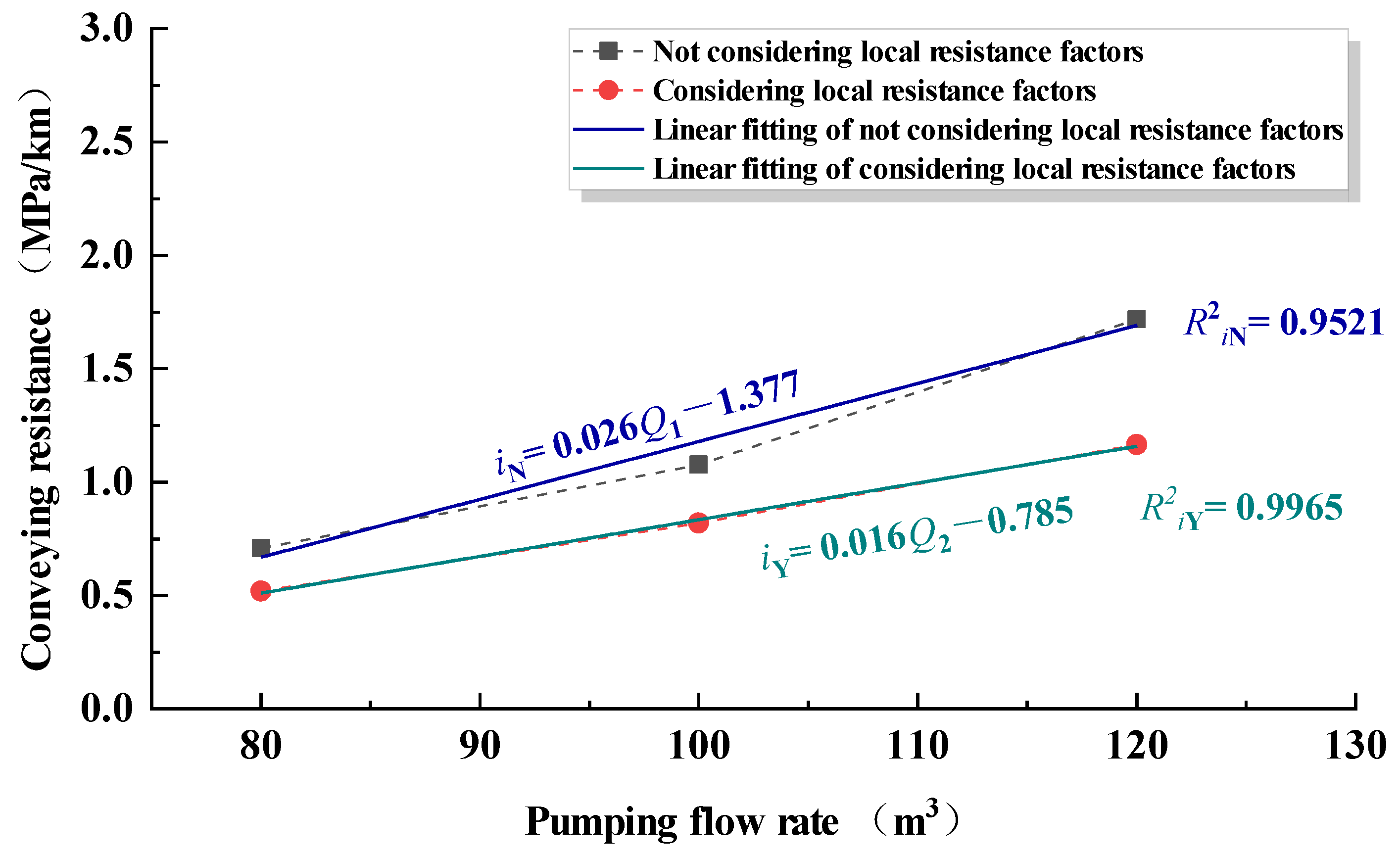
4.3.1. The Relationship Between the Pumping Flow Rate and Conveying Resistance

According to the long-distance pipeline transportation monitoring system, the pressure of each monitoring point along the pipeline at different pumping flow rate was obtained, as shown in Figure 6. According to the data, as it was far from the outlet of the grouting pump, the pressure along the pipeline showed a decreasing trend; as the pumping flow rate increased, the pressure at the exact location along the pipeline also showed an increasing trend, and the larger the pumping flow rate, the faster the pressure decreased along the pipeline. To further explore the relationship between the pipeline length and the pressure along the pipeline, the fitting curve of the pipeline length and the pressure along the pipeline under three pumping flow rates were obtained through data analysis. Still, the appropriate angle and the origin line graph could only be partially coincident. In this pipeline transportation test, the number of elbow sections in each section along the pipeline led to different local frictional losses in each section, which led to further transportation resistance in each section along the pipeline.
Based on the statistical analysis, the relationship between the spacing and pressure difference between the monitoring points of long-distance pipelines was obtained, as shown in Table 4. According to fluid mechanics and Table 1, the following relationship was established:
i i j = Δ P i j Δ L i j + x i j l e 0 + y i j l e 1
namely
P 2 P 1 ( L 2 L 1 ) + x 12 l e 0 + y 12 l e 1 = P 3 P 2 ( L 3 L 2 ) + x 23 l e 0 + y 23 l e 1 = P 4 P 3 ( L 4 L 3 ) + x 34 l e 0 + y 34 l e 1 = P 5 P 4 ( L 5 L 4 ) + x 45 l e 0 + y 45 l e 1
In the formula, iij is the conveying resistance between two adjacent monitoring points on the conveying pipeline, MPa/km. ΔPij is the pressure difference between two adjoining monitoring points on the conveying pipeline, MPa. ΔLij is the distance between two adjoining monitoring points on the transmission pipeline, km. xij is the number of 90-degree angles between two adjacent monitoring points on the conveying pipeline. yij is the number of 135-degree angles between two adjacent monitoring points on the conveying pipeline. le0 is the equivalent pipe length at a 90-degree angle, km. le1 is the equivalent pipe length at a 135-degree angle, km.
By substituting the data in Table 2 into Equation (2) and after calculating and taking the average value, it can be seen that when the pumping flow rate was 80 m3, le0 was 48.01 m and le1 was 29.76 m. When the pumping flow rate was 100 m3, le0 was 54.64 m and le1 was 33.74 m. When the pumping flow rate was 120 m3, le0 was 62.15 m and le1 was 38.11 m.
Combining the above calculation with Table 2, the relationship between the pumping flow rate and conveying resistance was obtained under two conditions: considering local resistance and not considering local resistance, as shown in Figure 7. As shown in the figure, as the pumping flow rate increased, the conveying resistance also increased, and the influence of the bent pipe sections on the conveying resistance also increased; when the pumping flow rate was the same, the measured and calculated conveying resistances were higher than the actual designating resistance, and as the pumping flow rate increased, the difference rate between the estimated and actual communicating resistance increased. Compared with the case of not considering local frictional losses, the fitting degree of the pumping flow and conveying resistance obtained by considering local frictional losses was higher.

4.3.2. Evaluation of the Effect of Long-Distance Pipeline Transportation

This long-distance pipeline transportation test transported about 180 m3 of clean water, 60 m3 of mortar, and 500 m3 of gangue slurry. There were no pipeline blockage incidents throughout the entire process. In addition, when the pumping flow rate was changed three times, except for the feedback data from the pressure gauge, there were no other abnormal phenomena. After the experiment, no large gangue particles were deposited at the bottom of the pipeline. That is to say, with the cooperation of the six transportation processes, 71% of the gangue slurry formed by “gangue + water” could be stably transported over a long distance.

5. Simulation Test of Grouting and Filling in Goafs

5.1. Gangue Accumulation Model and Test Process in Goafs

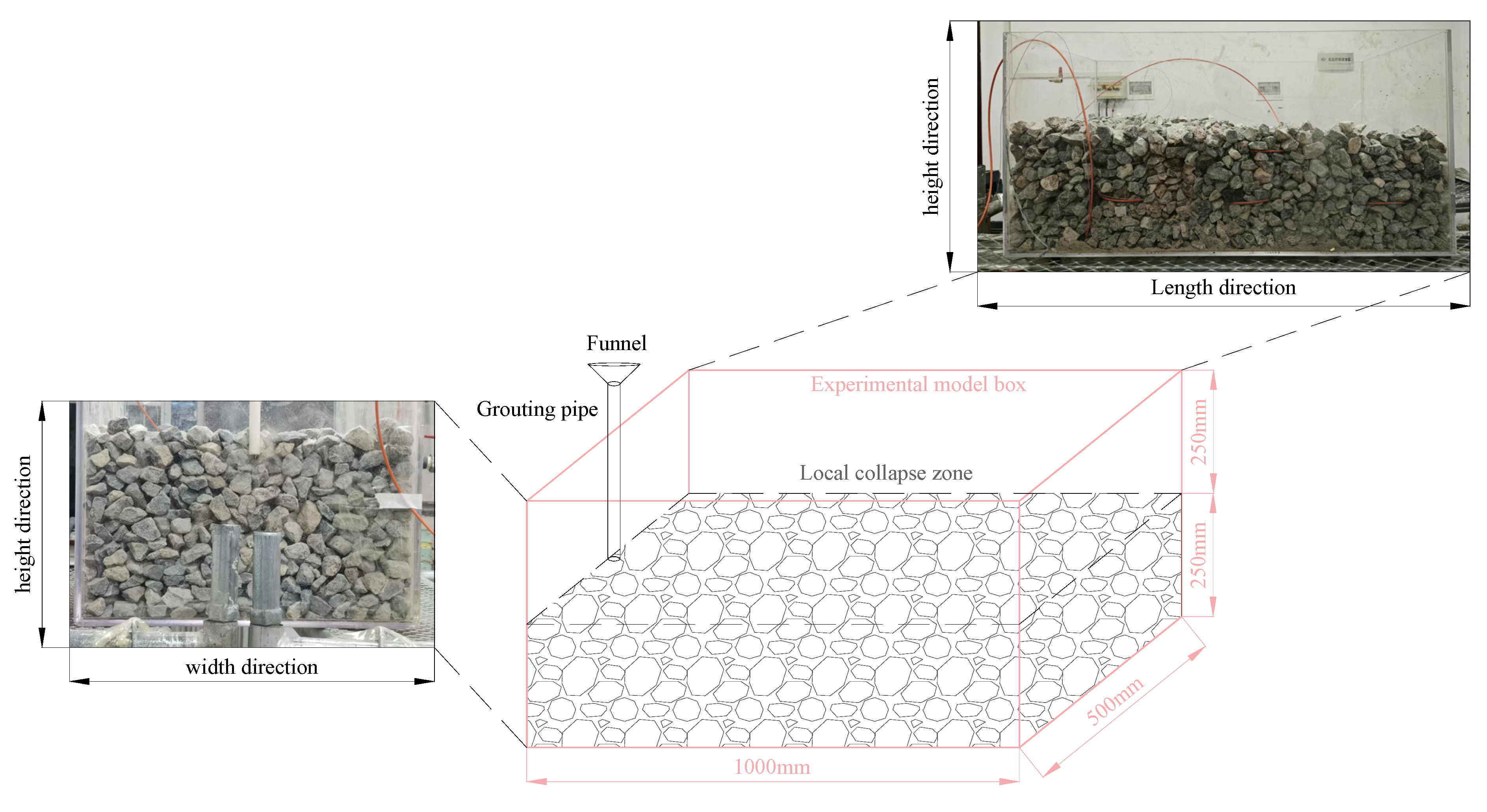
5.1.1. A Model of Gangue Accumulation in Local Collapse Zone

A test model box with a length, width, and height of 1.0 m, 0.5 m, and 0.5 m, respectively, was made using acrylic plate. In the test model box, different particle size fragments were placed to simulate the local state of the collapse zone with a porosity of 0.3. The height, width, and length of the collapse zone formed by accumulation were 0.25 m, 0.5 m, and 1.0 m, respectively. A PVC pipe with an inner diameter of 50 mm was placed in the middle of one side of the test model box to simulate the grouting pipe, as shown in Figure 8.

5.1.2. Process of Grouting Filling Simulation Test

The grouting filling simulation test was carried out in two steps. The first step was to make the crushed gangue powder and water into a gangue slurry with a mass fraction of 70% according to a ratio of 3:7. The second step was to inject the gangue slurry into the simulated collapse zone in the test model box through the funnel and grouting pipe and to observe and record the flow and diffusion law of the gangue slurry in the simulated collapse zone [37,38].

5.2. Analysis of Gangue Grouting Filling Test in Goafs

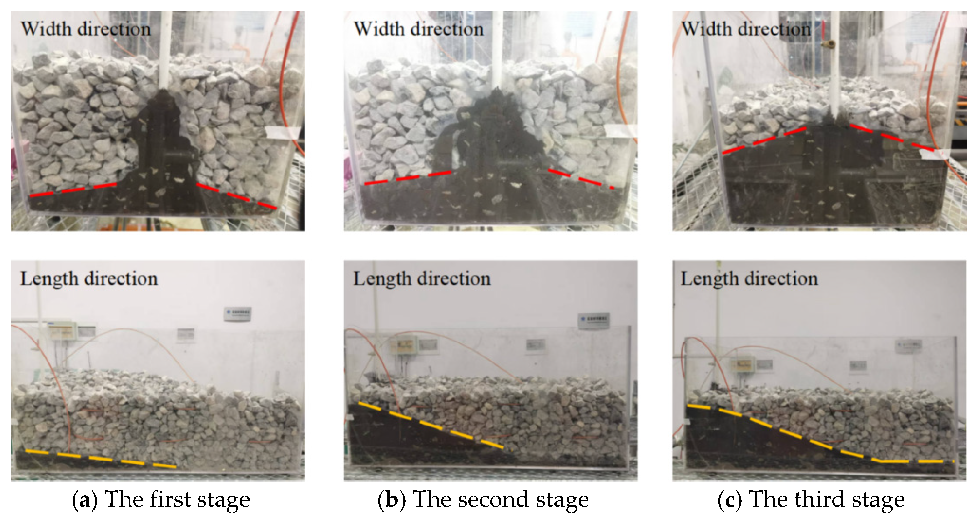
5.2.1. Flow Law of Gangue Slurry

According to the flow and diffusion law of the gangue slurry in the gap of the collapsed rock block in the simulated goaf during the test, the process can be divided into three stages:
The first stage was the free flow stage: the gangue slurry began to flow downward along the gap between the rock blocks from the slurry outlet and then began to diffuse around the gap between the rock blocks after the slurry reached the bottom of the experimental model box. The overall diffusion range was conical, as shown in Figure 9a.
The second stage was the stage of a self-flow slope: with the increase in the gangue injection amount, the width direction of the gangue slurry in the experimental model box was distributed in the shape of ‘eight’ and rose steadily, forming a slope of a certain angle in its length direction, and the newly added gangue slurry continuously scoured the slope and rose accordingly, as shown in Figure 9b.
The third stage was the accumulation stage at the bottom of the slope: with the increase in the amount of gangue injection, the gangue slurry flowed to the bottom of the slope along the length direction and gradually accumulated at the bottom of the slope, and the self-flow slope was no longer ‘linear’ but showed a convex ‘curve’, as shown in Figure 9c.

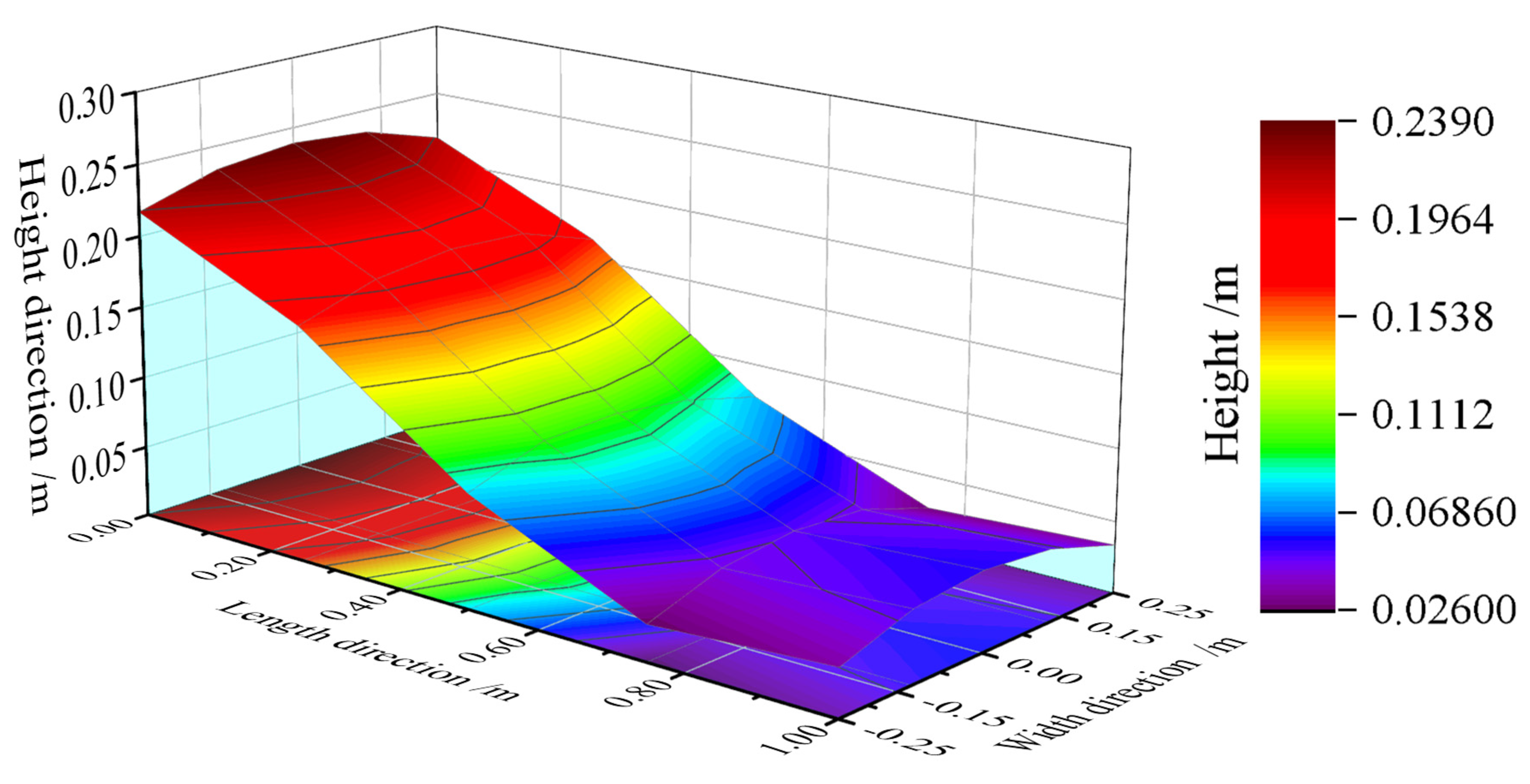
5.2.2. Distribution Pattern of Gangue Slurry

After the end of the test, the test model box was not stained with the gangue slurry block that needed to be removed, and then, using the actual measurements combined with drawing software, the distribution of the gangue slurry in the simulated goaf cloud was formed, as shown in Figure 10. The following can be seen from the figure:
(1)
The accumulation height of the gangue slurry was highest at the slurry outlet, and its height was 0.24 m. The minimum accumulation height of the gangue slurry was 0.026 m, which was located at 0.7 m in the length direction and ±0.25 m in the width direction, not at the boundary of the length direction of the test model box (1.0 m).
(2)
In the process of exposing the rock fragments, the gangue slurry did not fully fill the gaps between the rock fragments, and there was no gangue slurry between the local rock fragments, that is, the gangue slurry could not pass through the gaps between all the rock fragments.
Figure 10. Distribution of gangue slurry in the collapse zone.
Applsci 15 05475 g010

6. Industrial Test of Gangue Grouting Filling Technology in Goafs

6.1. Background of Grouting Filling Test

Zhangjiamao Coal Mine adopts the method of adit development, and it has set up three industrial sites, including a mine industrial site, a return air shaft site, and an air shaft site in the second panel. The grouting filling station of this test was located in the air shaft site in the second panel. The underground mining face of Zhangjiamao Coal Mine adopts a double roadway layout. At present, the number 22203 working face is mined, with a mining height of about 6.0 m, and the adjacent number 22202 working face has been mined out. In this experiment, the number 22203 mining roadway drilled upwardly inclined holes into the number 22202 goaf through a coal pillar section, and grouting filling was carried out in the number 22202 goaf.

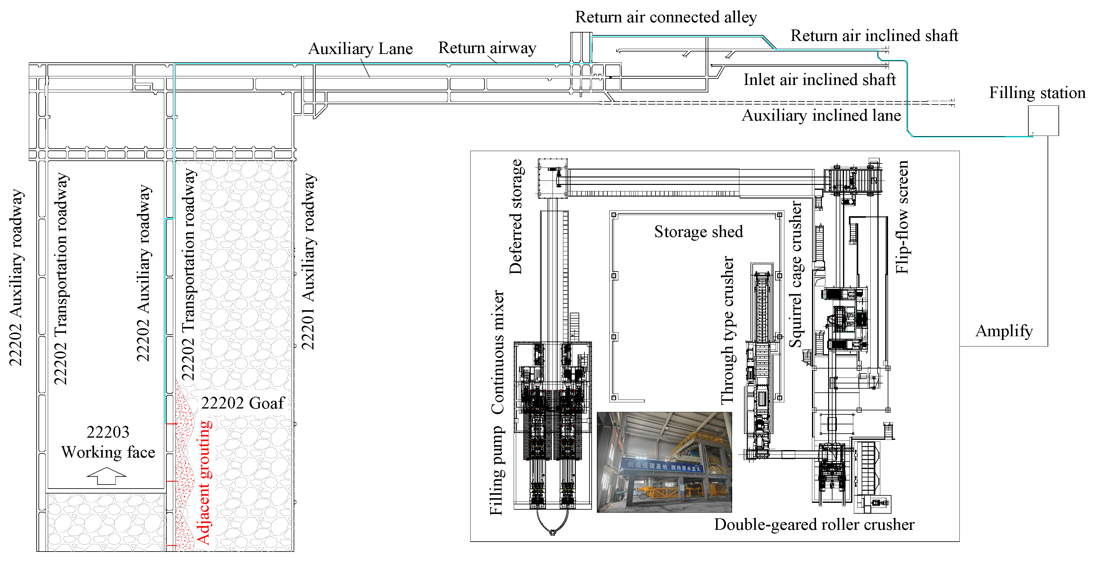
6.2. The Process and Layout of Grouting Filling

6.2.1. The Process of the Grouting Filling Test

The grouting filling test process can be divided into five steps, as shown in Figure 11.
(1)
The gangue in the gangue bin of the coal washing plant was transported by automobile to the storage shed.
(2)
The scraper was used to load the gangue to the first-stage crusher. The crushed gangue entered the second-stage crusher and then was transferred to the third-stage crusher through the belt, and it then entered the screening machine for screening. The finished gangue powder under the screen was transferred to the deferred storage through the well belt, and the unqualified gangue on the screen entered the third-stage crusher through the return belt to continue crushing.
(3)
The quantitative feeder under the deferred storage and water supply system transported the gangue powder and water to the first-stage mixer quantitatively according to a ratio of 7:3, and it then made the gangue slurry with a 70% concentration.
(4)
The gangue powder and water were stirred in the first-stage mixer, and the initially qualified gangue slurry overflowed to the second-stage mixer to continue stirring. Finally, the qualified gangue overflowed from the second-stage mixer to the hopper of the filling pump.
(5)
The filling pump transported the gangue slurry in the slurry hopper to the number 22202 goaf through the adjacent grouting borehole through the pipeline.
Figure 11. Test process and system layout of grouting filling technology in the goaf.
Applsci 15 05475 g011

6.2.2. Grouting Filling Equipment and Parameters

The ground filling station of Zhangjiamao Coal Mine adopts three stages of crushing, one stage of screening, one stage of buffering, two stages of stirring, and one stage of pumping equipment. The first-stage crusher is a through-type crusher, which can crush the washing gangue to less than 80 mm; the secondary crusher is a double-geared roller crusher, which can crush the gangue from below 80 mm to below 30 mm. The three-stage crusher is a squirrel cage crusher, which can crush the gangue from below 30 mm to below 3 mm. The flip-flow screen can realize the screening of the gangue below 3 mm; the volume of the deferred storage is 20 m3, which can meet the continuous operation of crushing screening and stirring pumping. The mixer is a two-stage continuous overflow mixer, and the filling pump is a plunger pump.
The filling pipeline route is as follows: filling station → air shaft site in the second panel → return air inclined shaft in the second panel → joint roadway of return air inclined shaft and return air roadway in the second panel → return air roadway → return air roadway → number 22202 auxiliary transportation roadway (number 22203 mining roadway) → adjacent grouting borehole → number 22202 goaf. The total length of the filling pipeline is about 4.6 km, and the pipeline model is a ϕ180 × 15 mm seamless steel pipe.
The adjacent grouting borehole spacing is 120 m, the borehole length is 28.0 m, the angle with the horizontal plane is 21°, the borehole diameter is ϕ200 mm, and a ϕ180 mm protective casing is used to protect the adjacent grouting filling borehole.

6.3. Process and Effect of Grouting Filling Test

During the adjacent grouting filling of the number 22202 goaf in the number 22202 auxiliary roadway of Zhangjiamao Coal Mine, the outlet pressure of the grouting filling pump was about 2.0 MPa, and the cumulative filling amount of a single borehole was about 1835 m3. After the pump was stopped for 28 h, there was no blockage or pressure rise, and the filling effect was good.

7. Conclusions

(1)
The concept of “fluidized filling” is proposed in this paper, and the principle, system composition, technical difficulties, and solutions of gangue grouting filling technology in goafs in a mine producing ten million tons of coal are provided.
(2)
A millimeter-grade gangue grouting material was developed, providing a gangue slurry concentration of 70.0~76.7%, corresponding to an upper limit of a 5 mm gangue particle size, 70~74.9%, corresponding to an upper limit of a 3 mm gangue particle size, 66.5~70.8%, corresponding to an upper limit of a 2.5 mm gangue particle size, and 60.0~63.5%, corresponding to an upper limit of a 1.25 mm gangue particle size.
(3)
The calculation method of frictional losses along the pipeline and local frictional losses are given. When the pumping flow was80~120 m3, the equivalent pipe length corresponding to a 90-degree elbow was 48.01~62.15 m, and the equal pipe length corresponding to a 135-degree elbow was 29.76~38.11 m, which verifies the feasibility of long-distance pipeline transportation of “gangue + water” two-phase flow.
(4)
Laboratory and field industrial grouting filling tests were carried out. Field experiments have shown that the gangue grouting filling technology in goafs can achieve the underground filling of ten million tons of coal gangue in a mine without affecting the average production of the mine.

Author Contributions

Methodology, H.P. and S.X.; Software, W.G. and F.Q.; Validation, H.P. and T.S.; Formal analysis, S.X., W.G. and D.C.; Investigation, T.S. and F.Q.; Data curation, W.G. and T.S.; Writing—original draft, H.P.; Writing—review and editing, S.X. and D.C. All authors have read and agreed to the published version of the manuscript.

Funding

This research received no external funding.

Institutional Review Board Statement

Not applicable.

Informed Consent Statement

Not applicable.

Data Availability Statement

The original contributions presented in this study are included in the article. Further inquiries can be directed to the corresponding authors.

Conflicts of Interest

The authors declare no conflicts of interest.

References

  1. Xie, H.P.; Ren, S.H.; Xie, Y.C.; Jiao, X.M. Development opportunities of the industry towards the goal of carbon neutrality. J. China Coal Soc. 2021, 46, 2197–2211. [Google Scholar]
  2. Xie, H.P.; Wang, J.H.; Wang, G.F.; Ren, H.Y.; Liu, J.Z.; Ge, S.R.; Zhou, H.W.; Wu, G.; Ren, S.H. New ideas of coal revolution and layout of coal science and technology development. J. China Coal Soc. 2018, 43, 1187–1197. [Google Scholar]
  3. Zhang, J.X.; Ju, Y.; Zhang, Q.; Ju, F.; Xiao, X.; Zhang, W.Q.; Zhou, N.; Li, M. Low ecological environment damage technology and method in coal mines. J. Minging Strat. Control Eng. 2019, 1, 56–68. [Google Scholar]
  4. Zhang, J.X.; Ju, Y.; Li, M.; Zhou, N.; Zhang, Q. Method of coal gangue separation and coordinated in-situ backfill mining. J. China Coal Soc. 2020, 45, 131–140. [Google Scholar]
  5. Wu, Q.; Liu, H.L.; Chen, Q.; Sun, W.J.; Chen, Y. Theoretical study of mine geo-environmental restoration model and its application. J. China Coal Soc. 2017, 42, 1085–1092. [Google Scholar]
  6. Wang, X.H.; Liu, F.; Ni, M.; Liu, Z.X. Research and application of spontaneous combustion control and ecological restoration of waste dump. Coal Sci. Technol. 2020, 48 (Suppl. S2), 128–131. [Google Scholar]
  7. Wu, Q.; Liu, H.L.; Zhao, H.Q.; Zhang, M.; Liu, S.Q.; Zeng, Y.F. Discussion on the nine aspects of addressing environmental problems of mining. J. China Coal Soc. 2019, 44, 10–22. [Google Scholar]
  8. Hu, B.N. Backfill mining technology and development tendency in China coal mine. Coal Sci. Technol. 2012, 40, 1–5. [Google Scholar]
  9. Yan, S.H.; Zhang, H.X. Status of filling mining technology in coal mines of China. Coal Min. Technol. 2008, 13, 1–3+10. [Google Scholar]
  10. Liu, J.G.; Li, X.W.; He, T. Application status and prospect of backfill mining in Chinese coal mines. J. China Coal Soc. 2020, 45, 141–150. [Google Scholar]
  11. Xu, J.L. Research and progress of coal mine green mining in 20 years. Coal Sci. Technol. 2020, 48, 1–15. [Google Scholar]
  12. Yang, S.L.; Bai, Y.G.; Li, J. Comprehensive analysis on present status of mine backfill mining and prospects. Coal Eng. 2013, 45, 4–6, 10. [Google Scholar]
  13. Zhou, N.; Zhang, J.X.; Ouyang, S.Y.; Deng, X.J.; Dong, C.W.; Du, E.B. Feasibility study and performance optimization of sand-based cemented paste backfill materials. J. Clean. Prod. 2020, 259, 120798. [Google Scholar] [CrossRef]
  14. Xu, J.L.; Xuan, D.Y.; Zhu, W.B.; Wang, X.Z.; Wang, X.L.; Teng, H. Study and application of coal mining with partial backfilling. J. China Coal Soc. 2015, 40, 1303–1312. [Google Scholar]
  15. Zou, H.Q.; Hou, C.J.; Sun, X.K.; Zhai, Q.D.; Chen, D.J. Solid waste paste filling for non-village-relocation coal mining. J. China Univ. Min. Technol. 2004, 33, 154–158. [Google Scholar]
  16. Miao, X.X.; Zhang, J.X.; Guo, G.L. Study on waste-filling method and technology in fully-mechanized coal mining. J. China Coal Soc. 2010, 35, 1–6. [Google Scholar]
  17. Xuan, D.Y.; Xu, J.L.; Zhu, W.B. Backfill mining practice in China coal mines. J. Mines Met. Fuels 2013, 61, 225–234. [Google Scholar]
  18. Zhu, W.B.; Xu, J.L.; Lai, W.Q.; Wang, Z.G. Research of isolated section-grouting technology for overburden bed separation space to reduce subsidence. J. China Coal Soc. 2007, 32, 458–462. [Google Scholar]
  19. Xu, J.L.; Ni, J.M.; Xuan, D.Y.; Wang, X.Z. Coal mining technology without village relocation by isolated grout injection into overburden. Coal Sci. Technol. 2015, 43, 8–11. [Google Scholar]
  20. Sun, J. Mechanics criterion and factors affecting overburden stability in solid dense filling mining. Int. J. Min. Sci. Technol. 2017, 27, 407–413. [Google Scholar] [CrossRef]
  21. Zhang, J.X.; Tu, S.H.; Cao, Y.J.; Tan, Y.L.; Xin, H.Q.; Pang, J.L. Research progress of technologies for intelligent separation and in-situ backfill in deep coal mines in China. J. Min. Saf. Eng. 2020, 37, 1–10. [Google Scholar]
  22. Huang, P.; Zhang, J.X.; Yan, X.J.; Anthony John Spencer Spearing; Li, M.; Liu, S.W. Deformation response of roof in solid backfilling coal mining based on viscoelastic properties of waste gangue. Int. J. Min. Sci. Technol. 2021, 31, 279–289. [Google Scholar] [CrossRef]
  23. Zhang, Y.; Cao, S.G.; Zhang, N.; Chang, Z. The application of short-wall block backfill mining to preserve surface water resources in northwest China. J. Clean. Prod. 2020, 261, 121232. [Google Scholar] [CrossRef]
  24. Xie, S.R.; Gao, M.M.; Chen, D.D.; Yue, S.S.; Pan, H.; Zeng, J.C.; Suo, H.X. Study on the distribution and evolution characteristics of spherical stress shell in backfilling mining stope. J. Min. Saf. Eng. 2019, 36, 16–23. [Google Scholar]
  25. Xu, P.; Zhou, Y.J.; Zhang, M.X.; Li, J.W.; Cao, Z.Z. Fracture development of overlying strata by backfill mining under thick alluvium and thin bedrock. J. Min. Saf. Eng. 2015, 32, 617–622. [Google Scholar]
  26. Liu, W.T.; Wu, H.F.; Shen, J.J. Based on Box-Behnken method superfine cement grouting material ratioandperformance optimization model. Coal Sci. Technol. 2024, 52, 146–158. [Google Scholar]
  27. Ruan, Z.N.; Wu, A.X.; Wang, Y.M.; Wang, S.Y.; Wang, J.D. Multiple response optimization of key performance indicators of cemented pastebackfill of total solid waste. Chin. J. Eng. 2020, 44, 496–503. [Google Scholar]
  28. Zhou, Z.B.; Liu, J.H.; Wu, R.D.; Wu, A.X.; Wang, H.J.; Wang, S.Y. Analysisof bleeding of low concentration full tailings filling materialand its regulate-control. Chin. J. Mater. Res. 2020, 34, 481–488. [Google Scholar]
  29. Wang, X.F.; Gao, M.Z.; Li, L.Q. Spatiotemporal coupling law of mining pressure strata movement and fracture field distribution in deep stope. J. Min. Saf. Eng. 2016, 33, 604–610. [Google Scholar]
  30. Yang, C.; Guo, L.J.; Zhang, L.; Hu, L.M.; Xu, W.Y. Study of the rheological characteristics of copper tailings and calculation of resistance in pipeline transportation. Chin. J. Eng. 2021, 39, 663–668. [Google Scholar]
  31. Hou, Y.Q.; Yin, S.H.; Dai, C.Q.; Cao, Y. Rheological properties and pipeline resistance calculation model in tailings paste. Chin. J. Nonferrous Met. 2021, 31, 510–519. [Google Scholar]
  32. Wang, H.J.; Wang, Y.; Wu, A.X.; Zhai, Y.G.; Jiao, H.Z. Research of paste new definition from the view point of saturation ratio and bleeding rate. J. Wuhan Univ. Technol. 2011, 33, 85–89. [Google Scholar]
  33. Wu, A.X.; Wang, H.J. Theory and Technology of Metal Ore Paste Filling; Science Press: Beijing, China, 2015. [Google Scholar]
  34. Yang, X.B.; Yan, Z.P.; Yin, S.H.; Yang, H. Transportation Pressure Model and Optimization of Coarse Aggregate Paste Backfill Based on Pipe Loop Test. J. Hunan Univ. (Nat. Sci.) 2022, 49, 181–191. [Google Scholar]
  35. Liu, H.L.; Hou, C.; Li, L.; Du, J.F.; Yan, B.X. Experimental investigation on flow properties of cemented paste backfill through L-pipe and loop-pipe tests. J. Cent. S. Univ. 2021, 28, 2830–2842. [Google Scholar] [CrossRef]
  36. Zheng, B.K.; Yao, W.; Huang, T.L.; Zhang, L.Y.; Yin, X.Y. Transportable performance of modified unclassed tailingsfilling slurry based on loop test. Chin. J. Nonferrous Met. 2021, 31, 520–529. [Google Scholar]
  37. Zhe, L.; Pan, H.; Gu, W.Z.; Zhao, M.Y.; Zhang, X.F.; Xu, K. Experimental study on flow and diffusion law of gangue filling slurry in caving zone. J. China Coal Soc. 2021, 46 (Suppl. S2), 629–638. [Google Scholar]
  38. Zhe, L.; Song, T.Q.; Gu, W.Z.; Xu, K.; Liu, Z.C.; Qiu, F.Q.; Yuan, C.F. Experimental research on transport-resistance characteristics of gangue slurry andits flow trend in goaf. J. China Coal Soc. 2022, 47 (Suppl. S1), 39–48. [Google Scholar]
Figure 1. Principle of gangue grouting filling technology in goafs.
Applsci 15 05475 g001
Figure 2. Technical difficulties and solutions of gangue grouting filling in goafs.
Applsci 15 05475 g002
Figure 3. Bleeding experiment of different gangue slurry gradations and concentrations.
Applsci 15 05475 g003
Figure 4. Slump experiment of different gangue slurry gradations and concentrations.
Applsci 15 05475 g004
Figure 5. Scheme and process of long-distance pipeline transportation test.
Applsci 15 05475 g005
Figure 6. Relationship between pipeline length and pressure along the pipeline.
Applsci 15 05475 g006
Figure 7. Relationship between pumping flow rate and conveying resistance.
Applsci 15 05475 g007
Figure 8. Gangue accumulation model in local collapse zone.
Applsci 15 05475 g008
Figure 9. Flow and diffusion law of gangue slurry.
Applsci 15 05475 g009
Table 1. Particle size distribution of original gangue samples after crushing.
Particle SizeProportion
>5.0 mm5.25%
3.0–5.0 mm10.03%
2.5–3.0 mm8.95%
1.25–2.5 mm13.35%
630 μm–1.25 mm12.95%
315–630 μm10.70%
<315 μm38.77%
Table 2. Bleeding rate of gangue slurry with different concentrations and particle size gradations.
Upper Limit of Particle Size
Mass Fraction
60%65%70%75%80%
5.00 mm33.76%29.71%4.93%2.25%0%
3.00 mm23.26%13.93%2.92%1.50%0%
2.50 mm13.50%6.50%1.75%0%0%
1.25 mm2.50%1.10%0.20%0%0%
0.63 mm0%0%0%0%0%
Table 3. Slump of gangue slurry with different concentrations and particle size gradations.
Upper Limit of Particle Size
Mass Fraction
60%65%70%75%80%
5.00 mm//141 mm130 mm120 mm
3.00 mm//140 mm130 mm50 mm
2.50 mm/145 mm135 mm115 mm35 mm
1.25 mm145 mm141 mm132 mm80 mm10 mm
0.63 mm142 mm139 mm125 mm40 mm10 mm
Table 4. Relationship between spacing and pressure difference between monitoring points of long-distance pipelines.
Spacing/kmNumber of 90-Degree Angles IncludedNumber of 135-Degree Angles IncludedPressure Difference at a Flow Rate of 80 m3/MPaPressure Difference at a Flow Rate of 100 m3/MPaPressure Difference at a Flow Rate of 120 m3/MPa
1.191020.901.482.21
0.45400.330.550.82
0.76300.470.751.10
1.641301.181.942.87
Disclaimer/Publisher’s Note: The statements, opinions and data contained in all publications are solely those of the individual author(s) and contributor(s) and not of MDPI and/or the editor(s). MDPI and/or the editor(s) disclaim responsibility for any injury to people or property resulting from any ideas, methods, instructions or products referred to in the content.

