Article

Multi-Unit Coupled Motion Hybrid Generator Based on a Simple Pendulum Structure

Center on Nano-Energy Research, Institute of Science and Technology for Carbon Peak & Neutrality, Guangxi Key Laboratory for the Relativistic Astrophysics, School of Physical Science & Technology, Guangxi University, Nanning 530004, China
*
Author to whom correspondence should be addressed.
Appl. Sci. 2025, 15(10), 5454; https://doi.org/10.3390/app15105454
Submission received: 15 March 2025 / Revised: 30 April 2025 / Accepted: 9 May 2025 / Published: 13 May 2025
(This article belongs to the Topic Advanced Energy Harvesting Technology, 2nd Edition)

Abstract

:
Wave energy is a widely distributed, abundant, and clean renewable energy source with tremendous potential for development. This study presents a multi-unit coupled motion hybrid generator (MCM-HG) based on a pendulum structure for harvesting low-frequency wave energy. The device integrates eight power generation units, including triboelectric nanogenerators (TENGs), electromagnetic generators (EMGs), and piezoelectric nanogenerators (PENGs), enhancing space utilization and energy conversion efficiency through coupled motion. Experiments show that at a frequency of 0.5 Hz and a swing angle of 15°, the MCM-HG achieves an output power of 22.07 mW and a power density of 7.36 Wm−3. The device successfully powers microelectronic devices, demonstrating its potential application value in the marine Internet of Things.

1. Introduction

With the continuous development and utilization of marine resources by humans, the Ocean Internet of Things (Ocean IoT) has emerged [1,2]. As a network system connecting various marine devices and sensors, the marine IoT offers innovative solutions for marine resource exploration, environmental monitoring, and marine disaster early warning [3,4,5]. Up to now, energy harvesting systems based on artificial intelligence (AI), and adaptive hybrid devices have gradually become research hotspots. In this field, energy harvesting devices, as the hardware foundation empowered by AI, play a crucial role [6,7,8]. However, the complexity and vastness of the marine environment pose significant challenges for traditional energy supply technologies in the marine IoT [9,10]. Additionally, the irregular amplitude and low frequency of wave energy limit the performance of traditional energy harvesting devices in converting blue energy [11,12,13]. Therefore, there is a pressing need to develop new devices capable of efficiently harvesting wave energy.
In recent years, the triboelectric nanogenerator (TENG) has been introduced for harvesting mechanical energy from the environment [14,15,16,17]. TENGs collect energy through the slight deformation of materials under external forces and are characterized by their small size, light weight, and strong scalability, making them highly suitable for wave energy harvesting [18,19,20,21,22,23]. Currently, energy harvesting devices based on swinging structures have garnered widespread attention due to their ability to operate under low-frequency excitation and produce multi-frequency outputs [24,25,26]. For example, Ren et al. developed a hybrid wave energy harvester (HW-NG) based on a pendulum structure, integrating TENGs and electromagnetic generators (EMGs) [27]. However, a large portion of the internal space in this structure remains underutilized. Similarly, Xu et al. designed and fabricated a durable rolling-based swinging structure triboelectric nanogenerator (RS-TENG) for low-frequency water wave energy harvesting [28]. When triggered by water waves, it can generate an output power of 4.27 mW, with a corresponding power density of 1.16 W/m3. Nevertheless, there is still a significant amount of unused space within this structure, leaving room for improvement in space utilization.
Addressing the issue of low space utilization in traditional swinging structures, this paper proposes a multi-unit coupled motion hybrid generator (MCM-HG) based on a simple pendulum structure. The device integrates eight power generation units, including triboelectric nanogenerators (TENGs), electromagnetic generators (EMGs), and piezoelectric nanogenerators (PENGs). The structural design, which integrates multiple power generation units, significantly enhances the utilization of internal space compared to traditional single-unit structures. Moreover, it achieves coupled motion between TENG units and EMG units, resulting in high voltage and large current outputs. The coupled motion between TENG units and PENG units enables multiple outputs from a single excitation. First, this paper systematically investigates the effects of the number of turns in the PCB coil and the range of magnetic flux cutting distance on the electrical output performance of the EMG unit; the mass of the simple pendulum and the support structure angle on the electrical output performance of the TENG unit; and the movement distance of the pulley clamp on the electrical output performance of the PENG unit. Next, the output performance of each power generation unit of the MCM-HG on a six-degree-of-freedom platform is studied. At a frequency of 0.5 Hz and a swing angle of 15°, the MCM-HG achieves an output power of 22.07 mW, with a corresponding power density of 7.36 W/m3, which is 5.35 times higher than that of traditional swinging structures. Finally, the electrical output characteristics of TENGs and EMGs connected in parallel with the same phase are demonstrated. Additionally, the ability of the MCM-HG to power microelectronic devices is verified. Therefore, this study provides a feasible approach for harvesting low-frequency wave energy, offering significant potential for practical applications in marine energy harvesting.

2. Materials and Methods

2.1. Fabrication of MCM-HG

The MCM-HG has a rectangular shape, assembled from acrylic plates, with an effective volume of 15 cm × 10 cm × 20 cm. The simple pendulum structure was manufactured using stereolithography resin (SL resin) through 3D printing technology. The pendulum shaft length is 100 mm, and the magnet holder measures 55 mm × 55 mm × 13 mm with a wall thickness of 3 mm. The hybrid generator comprises eight power generation units, including four TENG units (two S-TENGs and two P-TENGs; to facilitate differentiation, we refer to the TENG that is arranged in a fan shape at the lower layer as S-TENG, and the TENG that is integrated with PENG as P-TENG), two EMG units (P-EMG and C-EMG; to facilitate differentiation, we refer to the EMG composed of PCB coils as P-EMG and the EMG composed of coils as C-EMG), and two PENG units. The two S-TENGs are identical and symmetrically distributed on the lower layer. Each S-TENG consists of six contact-separation TENGs, measuring 50 mm × 60 mm. The friction layer is composed of a 0.1 mm copper sheet and a 0.08 mm PTFE film. The friction layer is attached to a 1.6 mm-thick acrylic plate measuring 60 mm × 80 mm. Each acrylic plate is adhered to a 0.2 mm-thick PTFE film and folded into a fan-shaped structure. The two P-TENGs are identical and symmetrically distributed on the upper layer, each comprising five contact-separation TENGs, measuring 50 mm × 50 mm. The friction layer consists of a 0.04 mm weakly magnetic silicon steel sheet and a 0.08 mm PTFE film. The EMG units are composed of coils and magnets. The P-EMG consists of eight custom-designed PCB coils, while the C-EMG contains two ordinary wound coils. Each wound coil has an inner diameter of 3.5 mm, an outer diameter of 20 mm, and 1500 turns. Both EMG units share a magnet measuring 50 mm × 50 mm × 10 mm. The two PENG units are identical, each containing five PZT piezoelectric ceramic plates measuring 30 mm × 50 mm × 0.6 mm, adhered to a weakly magnetic silicon steel sheet measuring 50 mm × 60 mm × 0.04 mm.

2.2. Electrical Measurements of MCM-HG

This study employs a linear motor (LinMot, Bo1-37×166/260, LinMot AG, Spreitenbach, Switzerland, made in Switzerland) to generate controllable horizontal linear motion (with programmable adjustment of acceleration, velocity, and displacement) while incorporating a six-degree-of-freedom platform to accurately simulate wave dynamic characteristics, including adjustable frequency, swing angle, and deterministic motion sequences. (In this study, the motion applied by the six-degree-of-freedom (6-DoF) platform (Nanjing Lingjing Automation Equipment Company, Nanjing, China, made in China) is deterministic, with a sinusoidal signal output, an oscillation frequency of 0.3–1.1 Hz, and an oscillation angle of 6–24°.) The output performance of the MCM-HG was measured under different excitation conditions. An electrometer (Keithley, 6514, Tektronix Company in Beaverton, OR, USA, made in China) and an oscilloscope (Tektronix, MDO3012, Tektronix Company in Beaverton, OR, USA, made in China) were employed for the relevant electrical performance tests.

3. Results and Discussion

3.1. Structure and Working Principle of MCM-HG

The structure and working principle of the MCM-HG are shown in Figure 1. The overall structure is rectangular, designed based on a simple pendulum structure, effectively integrating eight power generation units. The device is divided into two layers by a partition that features a U-shaped track. The upper layer includes two TENG units (P-TENG) and two PENG units, while the lower layer includes two TENG units (S-TENG) and two EMG units (P-EMG and C-EMG). This layered design maximizes the utilization of device space. The swinging block is composed of a magnet, which serves as a mass block to provide excitation for the power generation units and is also an essential part of the two EMG units, as shown in Figure 1a. Each power generation unit in the upper layer consists of five contact-separation TENGs and five PENGs, as shown in Figure 1b. The TENG friction layer consists of weakly magnetic silicon steel sheets and PTFE films, while the PENG is made of a PZT piezoelectric ceramic plate. The weakly magnetic silicon steel sheet with the PTFE film is fixed at the top of the MCM-HG structure, and the weakly magnetic silicon steel sheet with the PZT piezoelectric ceramic plate is attached to the pulley clamp. This design combines the TENG units with the PENG units to achieve coupled motion between the two units.
Each fan-shaped power generation unit in the lower layer is constructed from an acrylic plate and a PTFE film, consisting of six pairs of contact-separation TENGs and four spiral PCB coils, as shown in Figure 1c. The acrylic plate, chosen for its high strength, light weight, and excellent mechanical support properties, serves as the skeleton of the fan-shaped structure. An acrylic plate of the same thickness as the PCB coil is selected, with a shape cut out in the middle to embed the PCB coil. The PTFE film and copper sheet, serving as the friction layer of the TENG, are attached to the structure composed of the acrylic plate and the PCB coil. Each acrylic plate is connected to the supporting ramp via a PTFE film; the physical images of each unit and the entire device are detailed in Figure S1–S5 in the Supporting Information. This design combines the TENG units with the EMG units, achieving coupled motion between the two units while effectively solving the problem of the large volume and heavy weight of traditional coils, thereby improving space utilization.
Figure 1d explains the working principle of the device: when the device is tilted or subjected to horizontal inertial forces, the simple pendulum swings back and forth, thereby activating the TENGs, EMGs, and PENGs. The TENGs undergo contact separation, the magnetic flux through the EMG coils changes, and the PENGs deform to generate electrical energy. This process converts the mechanical energy from ocean waves into electrical energy. Figure 1e illustrates the working principle of the PENG units. The PENG and TENG units adopt a shared-carrier architecture design, with both units sharing a weakly magnetic silicon steel sheet substrate. Upon external excitation, the TENG unit undergoes contact separation, transmitting force to the silicon steel sheet and causing it to bend. The bending of the silicon steel sheet subsequently deforms the PZT ceramic sheet, where the piezoelectric effect induces the separation of positive and negative charges within the crystal. This charge imbalance generates a potential difference between the electrodes, producing current in the external circuit. The motion between the PENG and TENG units exhibits a certain phase difference, constituting phase-shifted motion. Taking the 0.5 Hz (T = 2 s) case where both units generate one output cycle as an example, TENG completes contact-separation and dominates output during 0–120 ms (forward) and 820–940 ms (reverse), while PENG achieves maximum bending and dominates output during 140–180 ms (forward) and 960–1100 ms (reverse), with an 85 ± 5 ms response delay relative to TENG triggering.
Figure 1f explains the working principle of the TENG units. Due to the different electrostatic properties of the PTFE film and the steel sheet, charge transfer occurs between the two materials upon contact through electrostatic induction and triboelectric effects. The PTFE film surface accumulates negative charges, while the copper sheet surface carries positive charges. When the two materials are separated, a potential difference is generated, forming an electric current. Figure 1g illustrates the working principle of the EMG units, operating on the principle of Faraday’s law of electromagnetic induction. As the simple pendulum swings back and forth, the PCB coils move with the fan-shaped structure, changing the magnetic flux. The magnetic flux through the coils fixed at the bottom also changes, generating alternating current.

3.2. Structural Design and Optimization of MCM-HG

Since the MCM-HG integrates eight power generation units with diverse output characteristics, it is necessary to study and optimize the structural parameters of each unit. To avoid the issues of large volume, heavy weight, and limited portability associated with traditional coils, specially designed spiral PCB coils were used in this study. The size of the PCB coils was determined to be 50 mm×50 mm, and the output performance of the P-EMG unit was investigated for different numbers of turns, ranging from 100 to 500 turns in increments of 100 turns. Figure 2a shows the changes in voltage and current of the P-EMG unit under different numbers of turns. Given the same magnetic field variation, the open-circuit voltage and short-circuit current increase with the number of turns. For example, at 100 turns, the open-circuit voltage of the P-EMG is 0.11 V, and the short-circuit current is 1 mA. When the number of turns reaches 400, these values increase to 0.62 V and 2 mA, respectively. However, with a fixed size of the PCB coil, more turns result in finer wire diameters and smaller currents. At 500 turns, the values are only 0.2 V and 0.4 mA. Therefore, to ensure the best output performance of the P-EMG, the number of turns in the PCB coil was chosen to be 400.
To validate the performance of the PCB coils, a linear motor was used to control the magnetic field variation and investigate the output performance. The experimental parameters were set as follows: acceleration range from 1.0 to 5.0 m/s2 with an increment of 1.0 m/s2; distance between the magnet and the PCB coil ranging from 1 to 9 cm with an increment of 2 cm. Figure 2b,c show the changes in voltage and current of the P-EMG unit. As the acceleration increases, the magnetic flux variation increases, and the output of the P-EMG also increases. The open-circuit voltage rises from 0.7 V to 2 V, and the short-circuit current increases from 0.22 mA to 0.62 mA. As the distance between the magnet and the PCB coil increases, the change in magnetic flux decreases, and the output of the P-EMG follows the same trend. The open-circuit voltage decreases from 1.2 V to 0.6 V, and the short-circuit current decreases from 0.37 mA to 0.19 mA as the distance increases from 1 cm to 9 cm. Considering the device design, an acceleration of 2 m/s2 and a distance of 5 cm between the magnet and the PCB coil were selected to achieve optimal output performance.
The swing of the simple pendulum significantly influences the output performance of the MCM-HG, making it essential to study and optimize the pendulum. Due to the track length limitation of the upper power generation units, the swing amplitude of the simple pendulum is fixed. Therefore, this paper only discusses the impact of the pendulum mass on the device output. Hollow trapezoidal acrylic structures were placed on both sides of the magnet block to expand the swing amplitude of the simple pendulum and serve as carriers for the counterweight blocks. As the mass of the simple pendulum increases from 110 g to 510 g, the force exerted on the S-TENG during swinging increases, and the contact between the friction layers becomes tighter. Consequently, the open-circuit voltage and short-circuit current of the S-TENG increase significantly, as shown in Figure 2d. However, when the pendulum mass increased from 410 g to 510 g, the improvement in S-TENG output performance was not significant. Moreover, the 510 g pendulum could not complete a reciprocating motion under the same excitation conditions due to its excessive mass. Therefore, we ultimately selected the 410 g pendulum.
Additionally, for the S-TENG, the opening angle directly affects the output performance. If the angle is too small or too large, the S-TENG will not open fully, resulting in a significant reduction in electrical output. Therefore, this paper investigates the angle of the ramp that the S-TENG relies on. The optimal ramp inclination angle of 9.3° was determined experimentally through repeated testing and data analysis. As shown in Figure 2e, when the ramp angle increases from 3.3° to 11.3°, the open-circuit voltage and short-circuit current of the S-TENG first increase and then decrease. Specifically, with a moderate increase in the ramp angle, the S-TENG opens more fully, thereby enhancing the output performance. However, when the angle exceeds a certain threshold, the opening of the S-TENG is restricted, and the performance declines. Based on the experimental results, a ramp angle of 9.3° is ultimately chosen, at which the output performance of the S-TENG is optimal.
For the PENG units, the pressure applied determines the degree of deformation of the PZT piezoelectric ceramic plates, thereby affecting the output performance of the PENG. In this structure, the pressure on the PENG is determined by the movement distance of the pulley clamp; the greater the distance, the greater the pressure. Therefore, a linear motor was also used to control the distance. The distance range was set from 0.5 to 2.5 cm with an increment of 0.5 cm. Figure 2f shows the changes in open-circuit voltage and short-circuit current of the PENG. As the distance increases, the open-circuit voltage rises from 3.7 V to 6 V, and the short-circuit current increases from 1 μA to 24 μA. Considering the output performance and space limitations, the movement distance of the pulley clamp was ultimately chosen to be 1.5 cm to achieve the best performance of the PENG units.

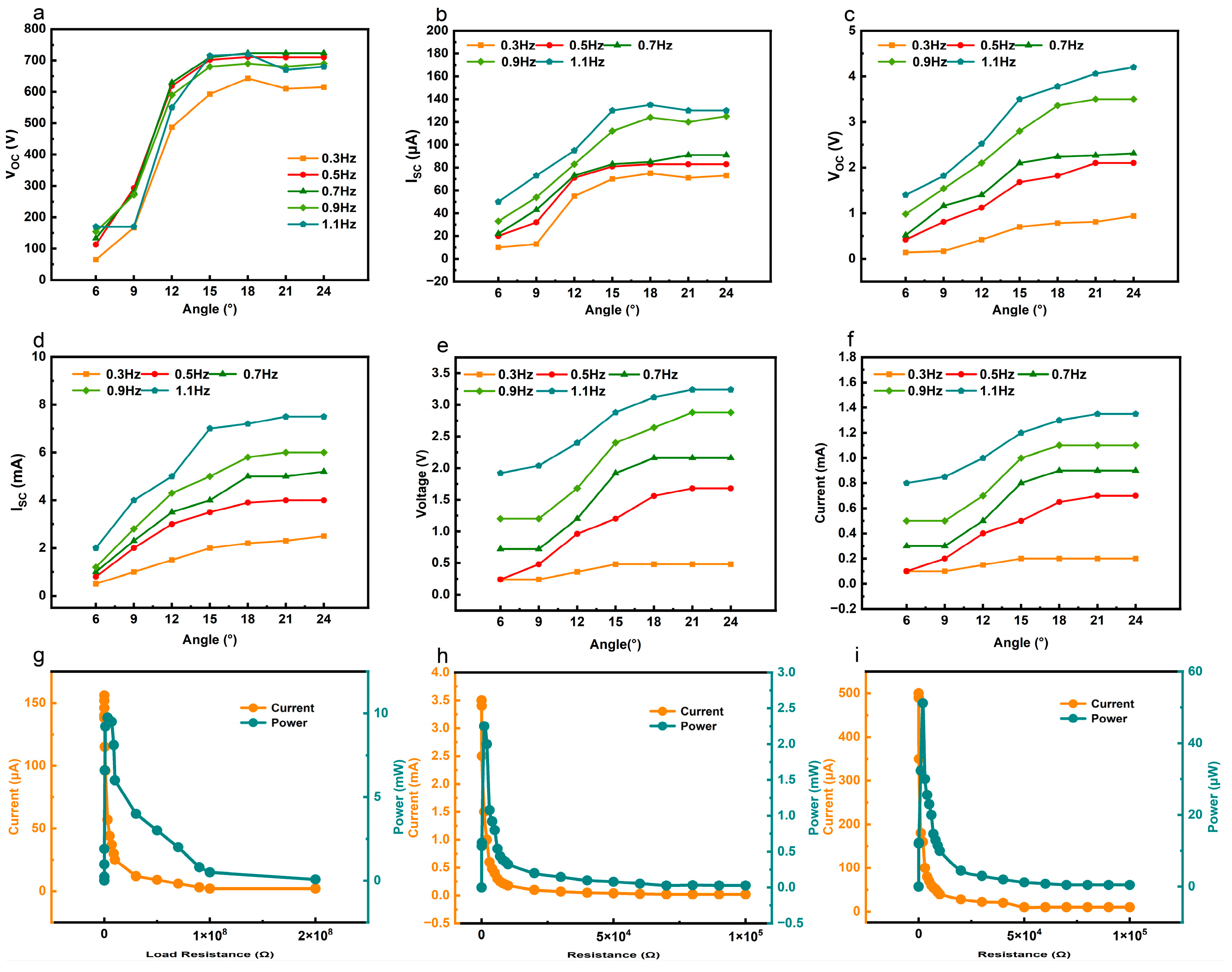
3.3. Output Performance of MCM-HG

This paper systematically investigates the ability of the MCM-HG to harvest wave energy. To simulate real ocean conditions, a six-degree-of-freedom platform was selected as the experimental platform. The typical power generation performance of the device, including open-circuit voltage (VOC), short-circuit current (ISC), and output power, was systematically measured. To avoid mismatch and performance interference between different power generation units, the output paths of the TENG, EMG, and PENG units in the MCM-HG are separated. Their optimal outputs are obtained under their respective external loads. In an MCM-HG, due to the completely symmetrical composition of the device, any one of the same power generation units can be selected for measurement. To better focus on the core research objectives, this paper does not investigate the potential effects of mechanical, electrical, and thermal factors on device output performance. As shown in Figure 3a,b, the VOC and ISC outputs of the S-TENG unit were measured at different angles (6–24°) and frequencies (0.3–1.1 Hz). The results indicate that, at the same frequency, the VOC increases and then slightly fluctuates around 700 V as the swing angle increases, and the ISC shows a similar trend. When the swing angle is constant, the ISC gradually increases with the increase in swing frequency, while the VOC remains relatively stable. At a swing angle of 18° and a frequency of 1.1 Hz, the maximum VOC and ISC values are 710 V and 135 μA, respectively. Figure 3c–f show the output performance of the two EMG units, with Figure 3c,d for C-EMG and Figure 3e,f for P-EMG. The VOC and ISC of the EMG units both increase with the angle and then tend to level off, and they increase with the frequency. At a swing angle of 24° and a frequency of 1.1 Hz, the maximum VOC and ISC values for C-EMG are 4.2 V and 7.5 mA, respectively. For P-EMG, the maximum VOC and ISC values are 3.2 V and 1.4 mA, respectively. At a swing angle of 15° and a frequency of 0.5 Hz, the maximum output powers of S-TENG, C-EMG, and P-EMG are 9.7 mW, 2.3 mW, and 51.2 μW, respectively, as shown in Figure 3g–i. The electromagnetic interference between EMG and TENG units will be further investigated in subsequent research projects.
It is noteworthy that the upper-layer power generation units of the MCM-HG exhibit multi-output characteristics during operation. By utilizing fixed clamps and highly elastic, weakly magnetic silicon steel sheets, the power generation units can produce multiple outputs from a single excitation due to the inertial force causing the steel sheets to swing repeatedly. With the six-degree-of-freedom platform set at a swing angle of 15°, a frequency of 0.5 Hz, and a duration of 30 s, the output performance of the P-TENG and PENG is shown in Figure 4. The results indicate that within one cycle, the P-TENG generates two significant outputs, with maximum values of VOC, ISC, and short-circuit transferred charge (Qsc) reaching 61 V, 16 μA, and 230 nC, respectively, as shown in Figure 4a–c. Figure 4d–f illustrate the output performance of the PENG. Since the PZT piezoelectric ceramic sheet generates electrical output upon deformation, it exhibits high sensitivity. Thus, each swing of the steel sheet produces one electrical output, resulting in five significant outputs per cycle, with maximum values of VOC, ISC, and Qsc reaching 3.1 V, 19 μA, and 203 nC, respectively. (The observed periodic quintuple outputs of PENG originate from the elastic vibration modes and inertial effects of the weakly magnetic steel sheet, representing typical forced-free vibration transition behavior rather than parasitic vibration or mechanical resonance phenomena.) The maximum output power of the P-TENG and PENG is measured to be 0.11 mW and 48 μW, respectively. In summary, the total output power of the MCM-HG is 22.07 mW, corresponding to a power density of 7.36 W/m3. To more clearly demonstrate the significant performance advantages of the integrated system, we have prepared a summary chart comparing the outputs of individual units (TENG, EMG, and PENG) with the total output of the integrated system, as shown in Table S1 of the Supporting Information.

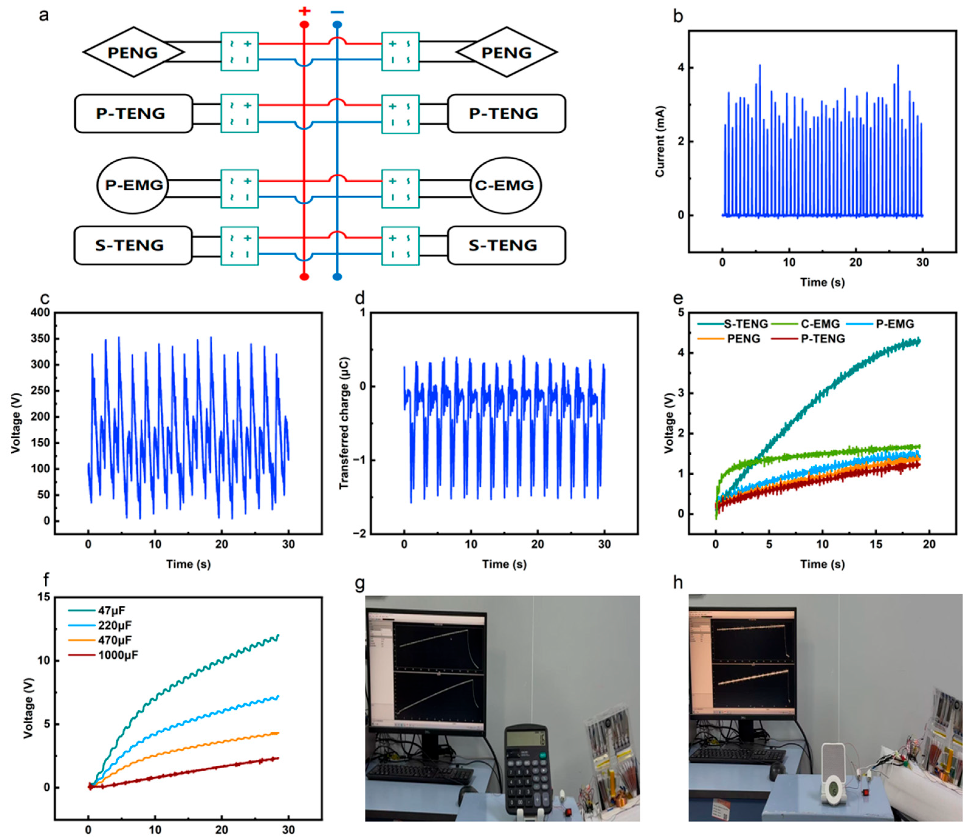
3.4. Demonstration of MCM-HG Applications

After independent testing of the eight power generation units, the overall performance of the MCM-HG was tested. To avoid mutual interference between the power generation units, a rectification-before-parallel connection method was chosen to integrate all the units, as shown in the circuit diagram in Figure 5a. Based on previous work, an ideal voltage source and an ideal current source can be paralleled, with the TENG considered as a current source and the EMG used as a voltage source [29,30]. When the TENG and EMG are paralleled and in phase, they can exhibit the large current characteristic of the EMG and the high voltage characteristic of the TENG. At a frequency of 0.5 Hz and a swing angle of 15°, the current and voltage of the MCM-HG are shown in Figure 5b,c, with measured peak current and voltage values of 4.1 mA and 353 V, respectively. The transferred charge is shown in Figure 5d, with a maximum transferred charge of 1.5 μC. (This study did not consider the impedance matching and phase synchronization issues in the TENG-EMG parallel system, nor did it quantitatively analyze their impact on the system’s output efficiency). The MCM-HG was used to charge capacitors, comparing the charging performance differences between individual units and the integrated system, as shown in Figure 5e,f. Figure 5e shows the charging curves of a single-side S-TENG, C-EMG, P-EMG, single-side PENG, and single-side P-TENG for a 47 μF capacitor. After 20 s, the capacitor voltages are 4.39 V, 1.72 V, 1.56 V, 1.47 V, and 1.33 V, respectively. The MCM-HG was used to charge capacitors of 47 μF, 220 μF, 470 μF, and 1000 μF. After 30 s, the capacitor voltages were 12 V, 7.2 V, 4.3 V, and 2.3 V, respectively. To further demonstrate the practicality of the MCM-HG, a 47 μF capacitor was used to power a calculator, and a 470 μF capacitor was used to power a thermo-hygrograph, as shown in Figure 5g–h (Videos S1 and S2). Additionally, we conducted durability tests on the devices. After 43,200 cycles, the transferred charge (Q) of the TENG decreased by 0.5% compared to the initial transferred charge (Q₀), the transferred charge (Q) of the PENG decreased by 4.9% compared to the initial transferred charge (Q₀), and the output current (I) of the EMG decreased by 5.5% compared to the initial output current (I₀) (Supporting Information, Figures S6–S8). The experimental results indicate that these units can maintain good performance after a large number of cycles, demonstrating high durability.

4. Conclusions

In summary, based on traditional swinging generators, this study innovatively designed a multi-unit coupled motion hybrid generator. The device integrates eight power generation units, comprising triboelectric nanogenerators (TENGs), electromagnetic generators (EMGs), and piezoelectric nanogenerators (PENGs), using simple pendulum motion as the excitation signal. Through the coupled motion design between different types of generators, the space utilization rate was significantly improved. At a frequency of 0.5 Hz and a swing angle of 15°, the S-TENG and EMG in the MCM-HG exhibited coupled motion, achieving peak output voltages of 353 V and peak currents of 4.1 mA after rectification. This combined high voltage and large current output leveraged the complementary advantages of both generators to achieve satisfactory results. Meanwhile, the P-TENG and PENG also demonstrated coupled motion, enabling multiple outputs from a single excitation within one cycle. The total output power of the MCM-HG was 22.07 mW, with a corresponding power density of 7.36 W/m3, which is 6.35 times higher than that of the rolling-based swinging structure triboelectric nanogenerator. Additionally, the MCM-HG performed well in practical applications: after charging a 47 μF capacitor to 5 V, it successfully powered a calculator; and after charging a 470 μF capacitor to 3 V, it successfully powered a thermo-hygrograph. These results indicate that the MCM-HG not only has significant advantages in low-frequency wave energy harvesting but also offers new ideas for marine energy collection and provides strong technical support for the sustainable development of future marine IoT.

Supplementary Materials

The following supporting information can be downloaded at https://www.mdpi.com/article/10.3390/app15105454/s1. Video S1: MCM-HG drives a calculator on a six-degree-of-freedom platform; Video S2: MCM-HG drives a thermo-hygrograph on a six-degree-of-freedom platform. Figure S1: The physical image of the PCB coil; Figure S2: The photo of the PCB coil embedded in the acrylic plate; Figure S3: The physical image of the S-TENG combined with the P-EMG; Figure S4: The physical image of the P-TENG combined with the PENG; Figure S5: The physical photograph of the MCM-HG; Figure S6: Durability testing of the TENG, with 43,200 cycles at a frequency of 0.5 Hz; Figure S7: Durability testing of the PENG, with 43,200 cycles at a frequency of 0.5 Hz; Figure S8: Durability testing of the EMG, with 43,200 cycles at a frequency of 0.5 Hz; Table S1: Individual Unit Output and Total Output of the Integrated System.

Author Contributions

Conceptualization, Y.L. and L.W.; methodology, Y.L. and L.W.; validation, Y.L.; writing—original draft preparation, Y.L.; writing—review and editing, all authors; supervision, L.W.; funding acquisition, L.W. All authors have read and agreed to the published version of the manuscript.

Funding

This research was funded by the National Key R&D Project from the Minister of Science and Technology, grant number 2021YFA1201603.

Institutional Review Board Statement

Not applicable.

Informed Consent Statement

Not applicable.

Data Availability Statement

The raw data supporting the conclusions of this article will be made available by the corresponding authors upon request.

Acknowledgments

The research was supported by all authors.

Conflicts of Interest

The authors declare no conflicts of interest.

References

  1. Stojanovic, M.; Preisig, J. Overview of networking protocols for underwater wireless communications. IEEE Commun. Mag. 2009, 47, 97–102. [Google Scholar] [CrossRef]
  2. Razzaq, A.; Ahmad, A.; Malik, A.W.; Fahmideh, M.; Ramadan, R.A. Software engineering for internet of underwater things to analyze oceanic data. Internet Things 2023, 24, 100893. [Google Scholar] [CrossRef]
  3. Baños, R.; Manzano-Agugliaro, F.; Montoya, F.G.; Gil, C.; Alcayde, A.; Gómez, J. Optimization methods applied to renewable and sustainable energy: A review. Renew. Sustain. Energy Rev. 2010, 14, 899. [Google Scholar] [CrossRef]
  4. Bar David, Y.; Geller, T.; Bistritz, I.; Ben-Gal, I.; Bambos, N.; Khmelnitsky, E. Wireless Body Area Network Control Policies for Energy-Efficient Health Monitoring. Sensors 2021, 21, 4245. [Google Scholar] [CrossRef]
  5. Hribernik, M.; Kos, A. Exploring the applicability of haptic actuators in aquatic environments. Internet Things 2023, 24, 100924. [Google Scholar] [CrossRef]
  6. Dong, L.; Li, J.; Zhang, H.; Gao, M.; Yang, Y.; Yang, F. Adaptive energy harvesting approach for smart wearables towards human-induced stochastic oscillations. J. Clean. Prod. 2023, 418, 138094. [Google Scholar] [CrossRef]
  7. Liu, Y.H.; Tse, C.K.; Yang, G.; Liao, Y.; Lin, H.; Dai, D.; Lin, H.; Hong, H.; Wu, H.; Zhang, X. Achieving Ultrahigh Efficiency of Triboelectric Nanogenerator Energy Harvesting Systems via Hybrid Electronic-Spark Power Management. Adv. Funct. Mater. 2024, 34, 2405338. [Google Scholar] [CrossRef]
  8. Xiao, Z.; Tan, P.; Xue, J.; Xi, Y.; Liu, M.; Zou, Y.; Zheng, Q.; Li, Z.; Wu, Y. Adaptive respiratory muscle trainer based on hybrid nanogenerator sensor and artificial intelligence. InfoMat 2025, 7, e70004. [Google Scholar] [CrossRef]
  9. Akyildiz, I.F.; Pompili, D.; Melodia, T. Underwater acoustic sensor networks: Research challenges. Ad Hoc Networks 2005, 3, 257–279. [Google Scholar] [CrossRef]
  10. Heidemann, J.; Stojanovic, M.; Zorzi, M. Underwater sensor networks: Applications, advances, and challenges. Philos. Trans. R. Soc. A 2012, 370, 158–175. [Google Scholar] [CrossRef]
  11. Jung, S.; Lee, J.; Hyeon, T.; Lee, M.; Kim, D.H. Fabric-based integrated energy devices for wearable activity monitors. Adv. Mater. 2014, 26, 6329–6334. [Google Scholar] [CrossRef] [PubMed]
  12. Zhao, L.-C.; Zou, H.-X.; Xie, X.; Guo, D.-H.; Gao, Q.-H.; Wu, Z.-Y.; Yan, G.; Wei, K.-X.; Zhang, W.-M. Mechanical intelligent wave energy harvesting and self-powered marine environment monitoring. Nano Energy 2023, 108, 108230. [Google Scholar] [CrossRef]
  13. Wang, W.; Yang, D.; Yan, X.; Wang, L.; Hu, H.; Wang, K. Triboelectric nanogenerators: The beginning of blue dream. Front. Chem. Sci. Eng. 2023, 17, 635–678. [Google Scholar] [CrossRef]
  14. Fan, F.-R.; Tian, Z.-Q.; Wang, Z.L. Flexible Triboelectric Generator. Nano Energy 2012, 1, 328–334. [Google Scholar] [CrossRef]
  15. Wang, Z.L. Triboelectric nanogenerators as new energy technology and self-powered sensors-Principles, problems and perspectives. Faraday Discuss. 2014, 176, 447–458. [Google Scholar] [CrossRef]
  16. Fan, F.R.; Tang, W.; Wang, Z.L. Flexible Nanogenerators for Energy Harvesting and Self-Powered Electronics. Adv. Mater. 2016, 28, 4283–4305. [Google Scholar] [CrossRef]
  17. Liang, X.; Jiang, T.; Liu, G.; Xiao, T.; Xu, L.; Li, W.; Xi, F.; Zhang, C.; Wang, Z.L. Triboelectric Nanogenerator Networks Integrated with Power Management Module for Water Wave Energy Harvesting. Adv. Funct. Mater. 2019, 29, 1807241. [Google Scholar] [CrossRef]
  18. Khan, U.; Kim, S.-W. Triboelectric Nanogenerators for Blue Energy Harvesting. ACS Nano 2016, 10, 6429–6432. [Google Scholar] [CrossRef]
  19. Viet, N.V.; Wu, N.; Wang, Q. A Review on Energy Harvesting from Ocean Waves by Piezoelectric Technology. J. Model. Mech. Mater. 2017, 1, 20160161. [Google Scholar] [CrossRef]
  20. Rodrigues, C.; Nunes, D.; Clemente, D.; Mathias, N.; Correia, J.M.; Rosa-Santos, P.; Taveira-Pinto, F.; Morais, T.; Pereira, A.; Ventura, J. Emerging Triboelectric Nanogenerators for Ocean Wave Energy Harvesting: State of the Art and Future Perspectives. Energy Environ. Sci. 2020, 13, 2657–2683. [Google Scholar] [CrossRef]
  21. Wu, H.; Wang, Z.; Zi, Y. Multi-mode Water-tube-based Triboelectric Nanogenerator Designed for Low-frequency Energy Harvesting with Ultrahigh Volumetric Charge Density. Adv. Energy Mater. 2021, 11, 2100038. [Google Scholar] [CrossRef]
  22. Li, J.; Chen, J.; Guo, H. Triboelectric Nanogenerators for Harvesting Wind Energy: Recent Advances and Future Perspectives. Energies 2021, 14, 6949. [Google Scholar] [CrossRef]
  23. Xiang, H.; Zeng, Y.; Huang, X.; Wang, N.; Cao, X.; Wang, Z.L. From Triboelectric Nanogenerator to Multifunctional Triboelectric Sensors: A Chemical Perspective toward the Interface Optimization and Device Integration. Small 2022, 18, 2107222. [Google Scholar] [CrossRef] [PubMed]
  24. Yuan, Z.; Wei, X.; Jin, X.; Sun, Y.; Wu, Z.; Wang, Z.L. Magnetic energy harvesting of transmission lines by the swinging triboelectric nanogenerator. Mater. Today Energy 2021, 21, 100848. [Google Scholar] [CrossRef]
  25. Demircioglu, O.; Cicek, M.O.; Doganay, D.; Gazaloglu, G.; Baykal, C.; Cinar, S.; Unalan, H.E. Triboelectric Nanogenerators for Blue Energy Harvesting in Simulated Wave Conditions. Nano Energy 2022, 108, 108157. [Google Scholar] [CrossRef]
  26. Zhang, C.; Yuan, W.; Zhang, B.; Yang, J.; Hu, Y.; He, L.; Zhao, X.; Li, X.; Wang, Z.L.; Wang, J. A Rotating Triboelectric Nanogenerator Driven by Bidirectional Swing for Water Wave Energy Harvesting. Small 2023, 19, 2304412. [Google Scholar] [CrossRef]
  27. Ren, Z.W.; Liang, X.; Liu, D.; Li, X.J.; Ping, J.F.; Wang, Z.M.; Wang, Z.L. Water-Wave Driven Route Avoidance Warning System for Wireless Ocean Navigation. Adv. Energy Mater. 2021, 11, 2101116. [Google Scholar] [CrossRef]
  28. Xu, Z.; Chen, L.; Zhang, Z.; Han, J.; Chen, P.; Hong, Z.; Jiang, T.; Wang, Z.L. Durable Roller-Based Swing-Structured Triboelectric Nanogenerator for Water Wave Energy Harvesting. Small 2023, 19, 2307288. [Google Scholar] [CrossRef]
  29. Zhao, T.; Niu, B.; Xie, G.; Hu, C.; Liu, B.; Xu, M.; Ma, Y. A High Output Triboelectric–Electromagnetic Hybrid Generator for Water Wave Energy Harvesting. Adv. Mater. Technol. 2022, 7, 2101485. [Google Scholar] [CrossRef]
  30. Ding, J.; Jiang, J.; Lin, T.; Liu, G.; Yao, H.; Wen, H.; Li, S.; Mo, F.; Wan, L. Realization of a Sustainable Charging Power Source by In Situ Low-Frequency Water Wave Energy Harvesting with a Coaxial Triboelectric–Electromagnetic Hybrid Generator. Adv. Energy Sustain. Res. 2022, 3, 2200087. [Google Scholar] [CrossRef]
Figure 1. Structural design and working mechanism diagram of MCM-HG. (a) Schematic of the structure of the MCM-HG; structural details of (b) PENG and P-TENG, (c) S-TENG and P-EMG; (d) the process of movement in the waves; the working principles of (e) PENG units, (f) S-TENG units, and (g) EMG units.
Applsci 15 05454 g001
Figure 2. Kinematic characteristics and optimization of MCM-HG. The output performance of P-EMG (a) under different numbers of turns, (b) under different acceleration levels, and (c) at different distances between the magnet; (d) the impact of magnet mass on the output of S-TENG; (e) the effect of ramp angle on the output of S-TENG; (f) the output performance of PENG under different movement distances.
Applsci 15 05454 g002
Figure 3. The output performance of S-TENG, C-EMG, and P-EMG. (a) The open-circuit voltage and (b) short-circuit current of S-TENG at a frequency of 0.3–1.1 Hz and angle of 6–24°; (c) the open-circuit voltage and (d) short-circuit current of C-EMG at a frequency of 0.3–1.1 Hz and angle of 6–24°; (e) the open-circuit voltage and (f) short-circuit current of P-EMG at a frequency of 0.3–1.1 Hz and angle of 6–24°; the output power of (g) S-TENG, (h) C-EMG, and (i) P-EMG at frequency 0.5 Hz and angle 15° under different external loads.
Applsci 15 05454 g003
Figure 4. The output performance of P-TENG and PENG. (a) The open-circuit voltage, (b) short-circuit current, and (c) short-circuit transfer charge of P-TENG at a frequency of 0.5 Hz and angle of 15°; (d) the open-circuit voltage, (e) short-circuit current, and (f) short-circuit transfer charge of PENG at a frequency of 0.5 Hz and angle of 15°.
Applsci 15 05454 g004
Figure 5. Circuit connection of MCM-HG, output characteristics, charging characteristics, and driving electronic devices. (a) Circuit connection of MCM-HG; (b) the open-circuit voltage, (c) short-circuit current, and (d) short-circuit transfer charge of MCM-HG at a frequency of 0.5 Hz and angle of 15°; (e) charging properties of S-TENG, C-EMG, P-EMG, PENG, and PENG charging a 47 μF capacitor; (f) charging characteristics of MCM-HG; (g) charging a 47 μF capacitor to drive a calculator, and (h) charging a 470 μF capacitor to drive a thermo-hygrograph.
Applsci 15 05454 g005
Disclaimer/Publisher’s Note: The statements, opinions and data contained in all publications are solely those of the individual author(s) and contributor(s) and not of MDPI and/or the editor(s). MDPI and/or the editor(s) disclaim responsibility for any injury to people or property resulting from any ideas, methods, instructions or products referred to in the content.

