Study on Crack Development of Frame Beams with U-Shaped Engineered Cementitious Composites Cover Layer Under Negative Moments


Abstract
1. Introduction
2. Frame Beam with ECC Protective Layer
2.1. Status of ECC Protective Layer
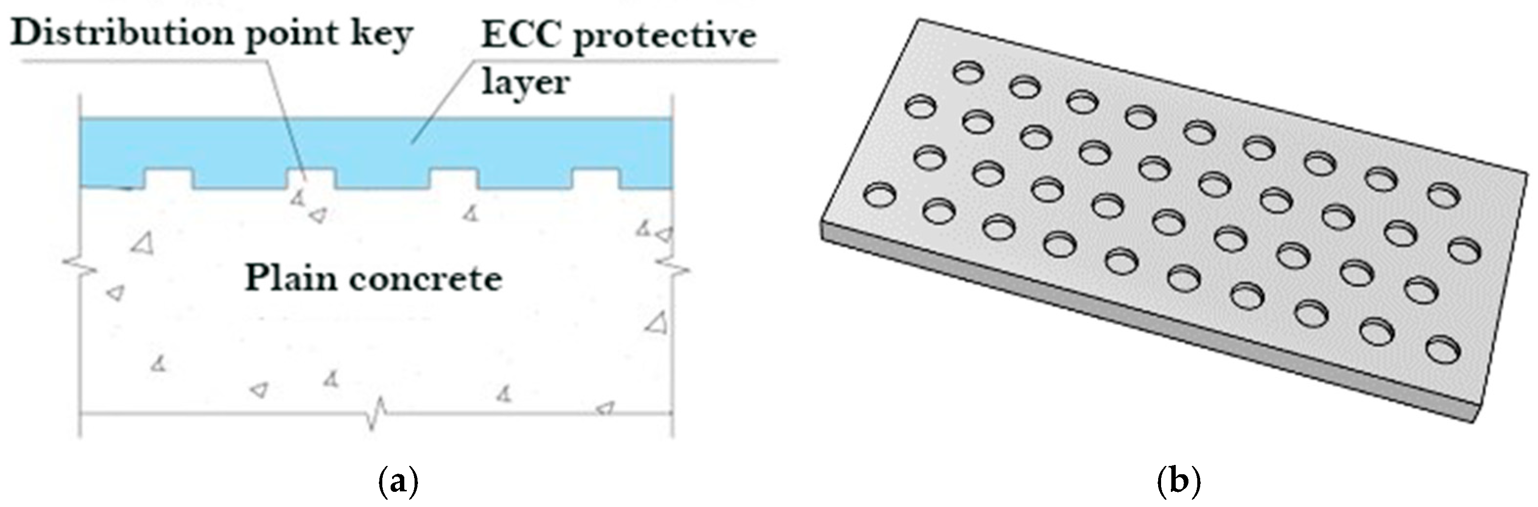
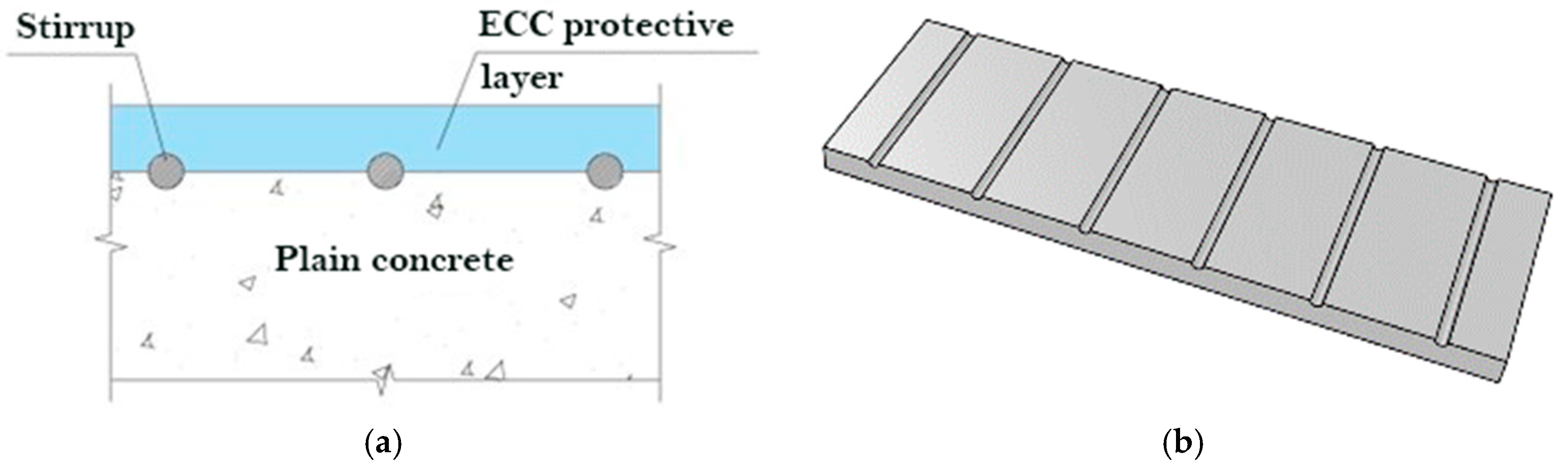
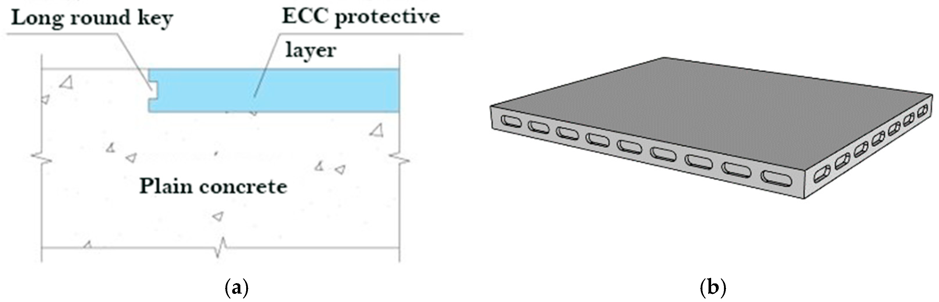
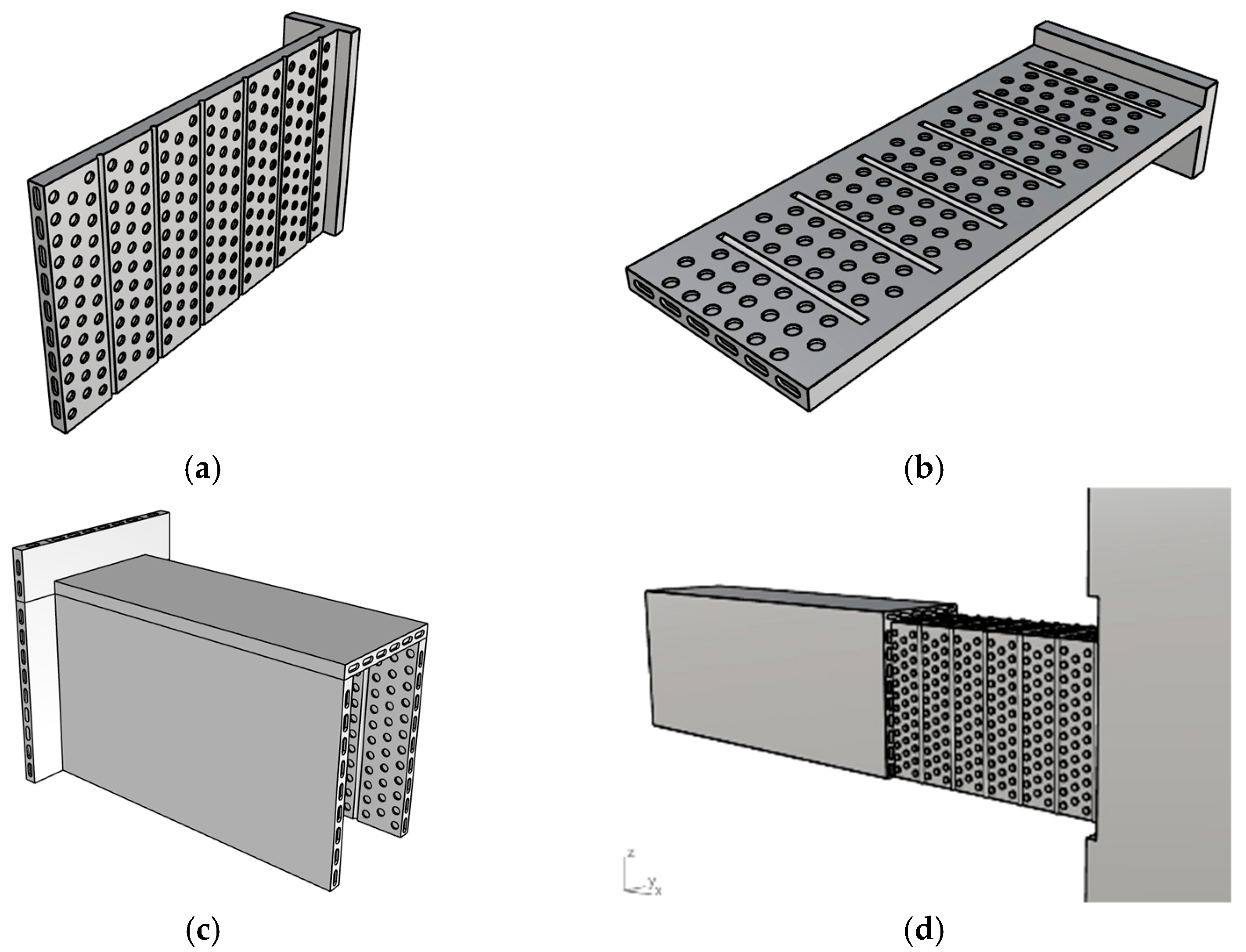
2.2. Structural Construction of ECC Protective Layer
3. Test Survey
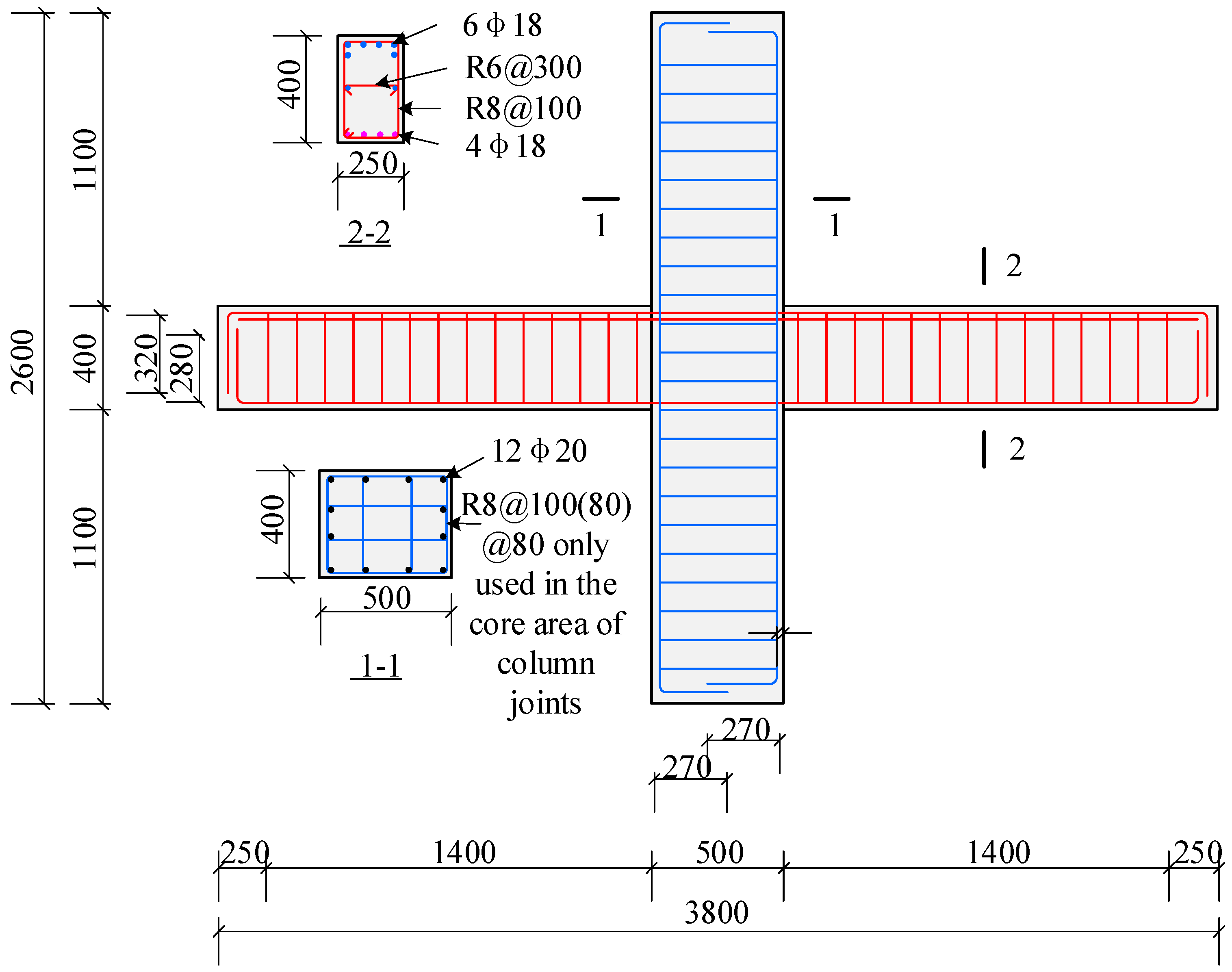
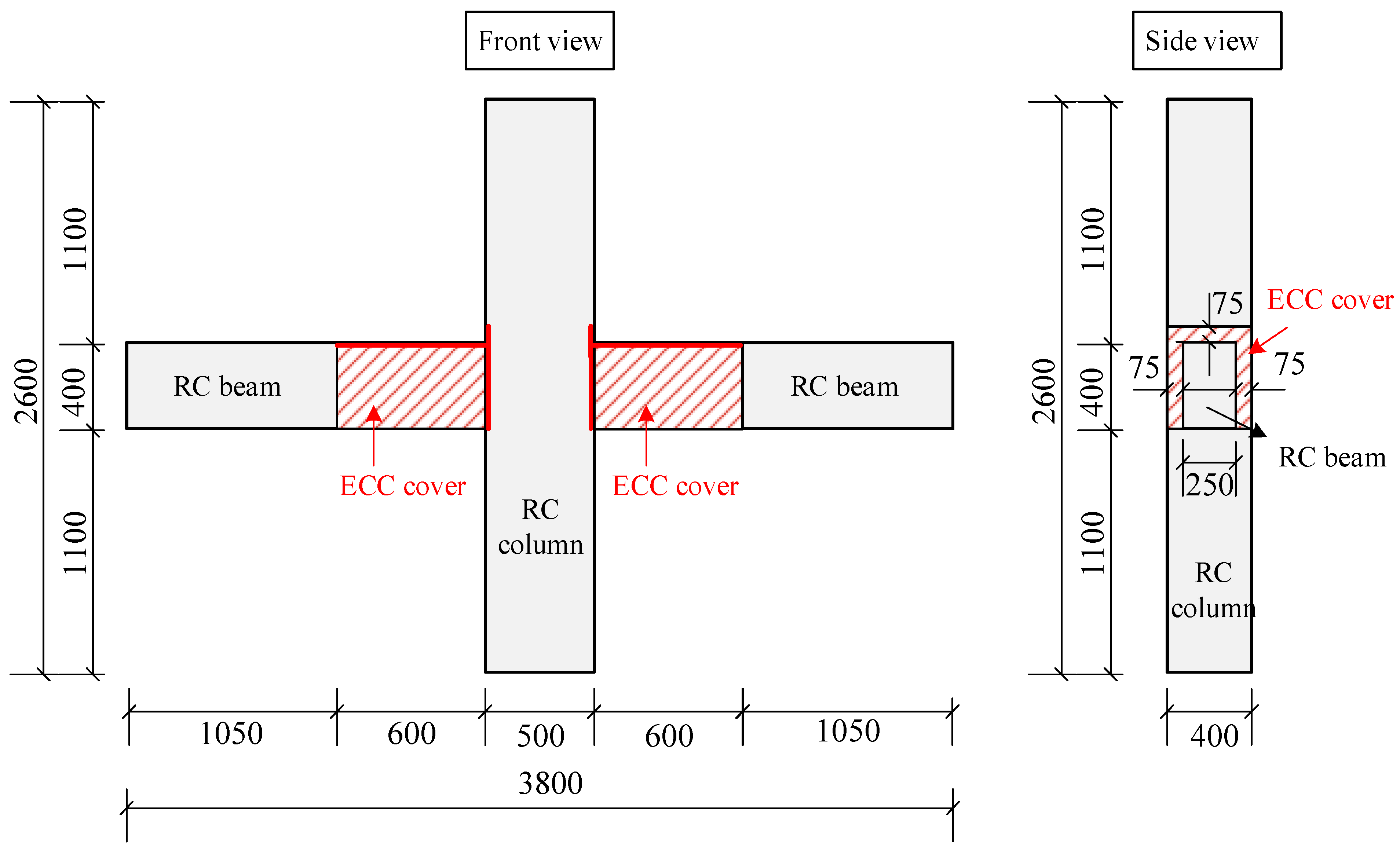
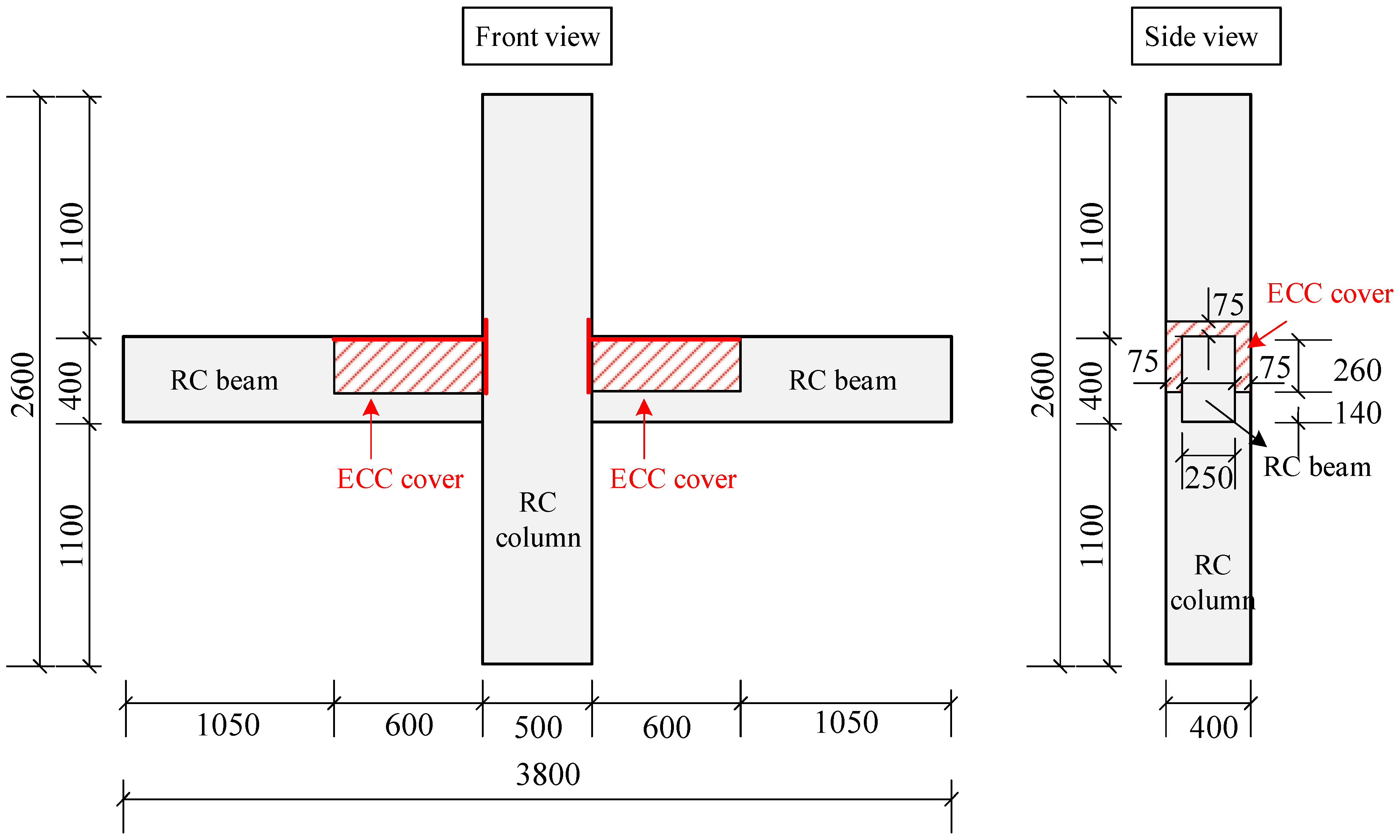
3.1. Design and Manufacture of Specimen
3.2. Material Properties
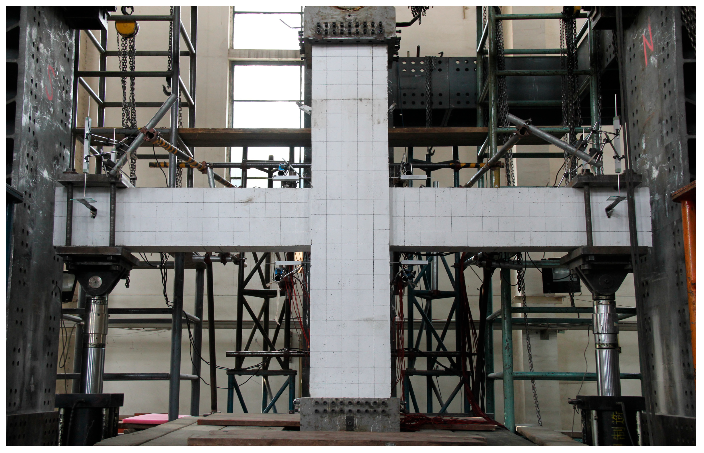
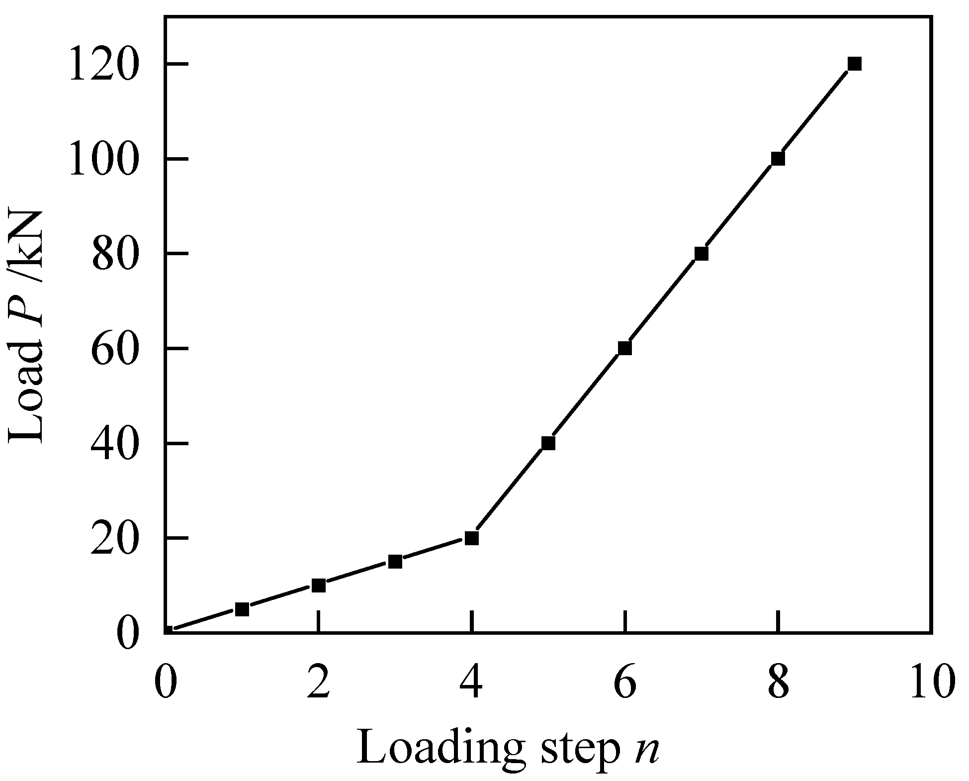
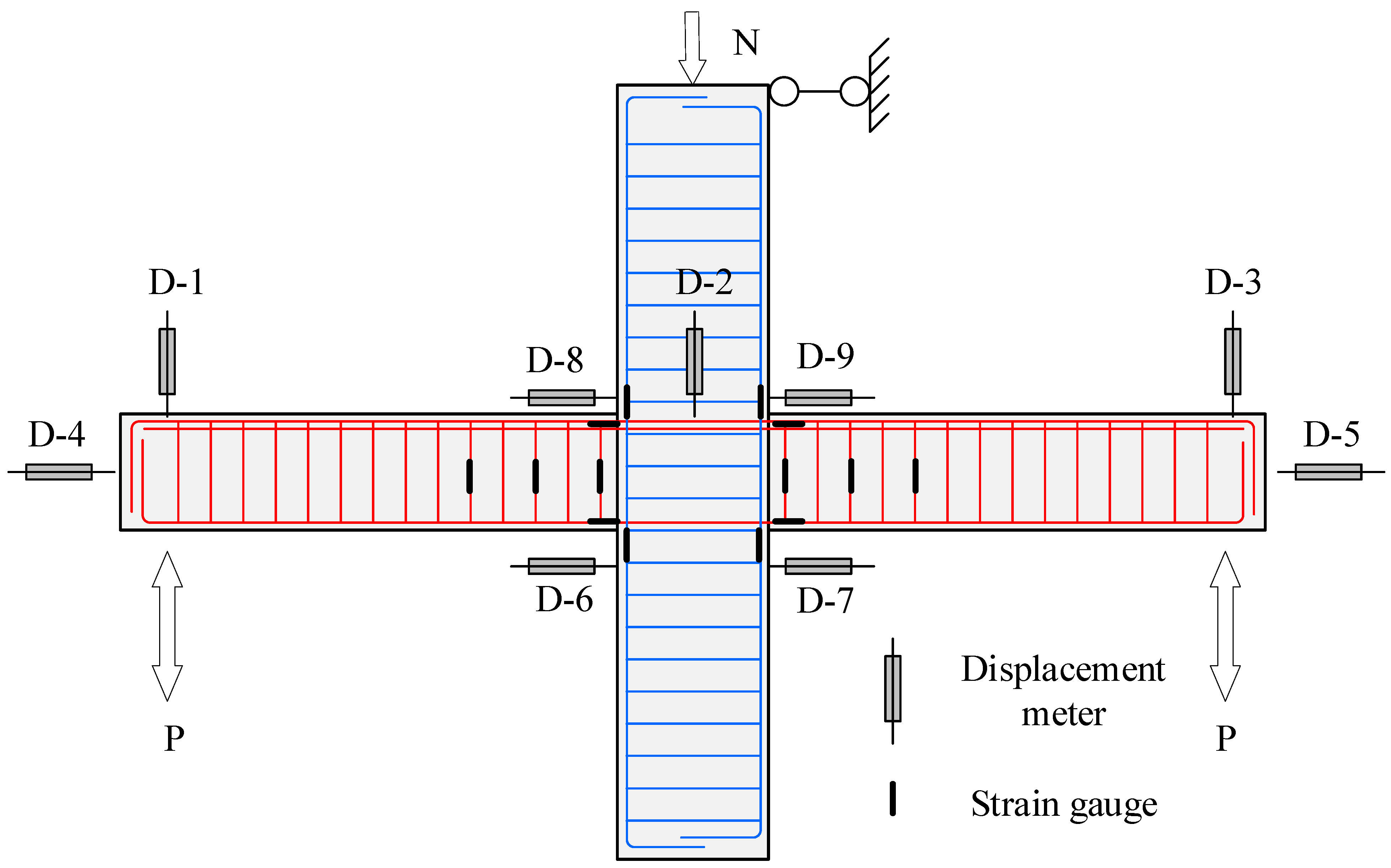
3.3. Test Loading and Measurement
4. Theoretical Analysis of Maximum Crack Width in Negative Moment Zone
4.1. Calculation of Flexural Bearing Capacity of Normal Section
4.2. Shear Bearing Capacity Calculation of Inclined Section
4.3. Calculation of Maximum Crack Width
5. Study on Fracture Development
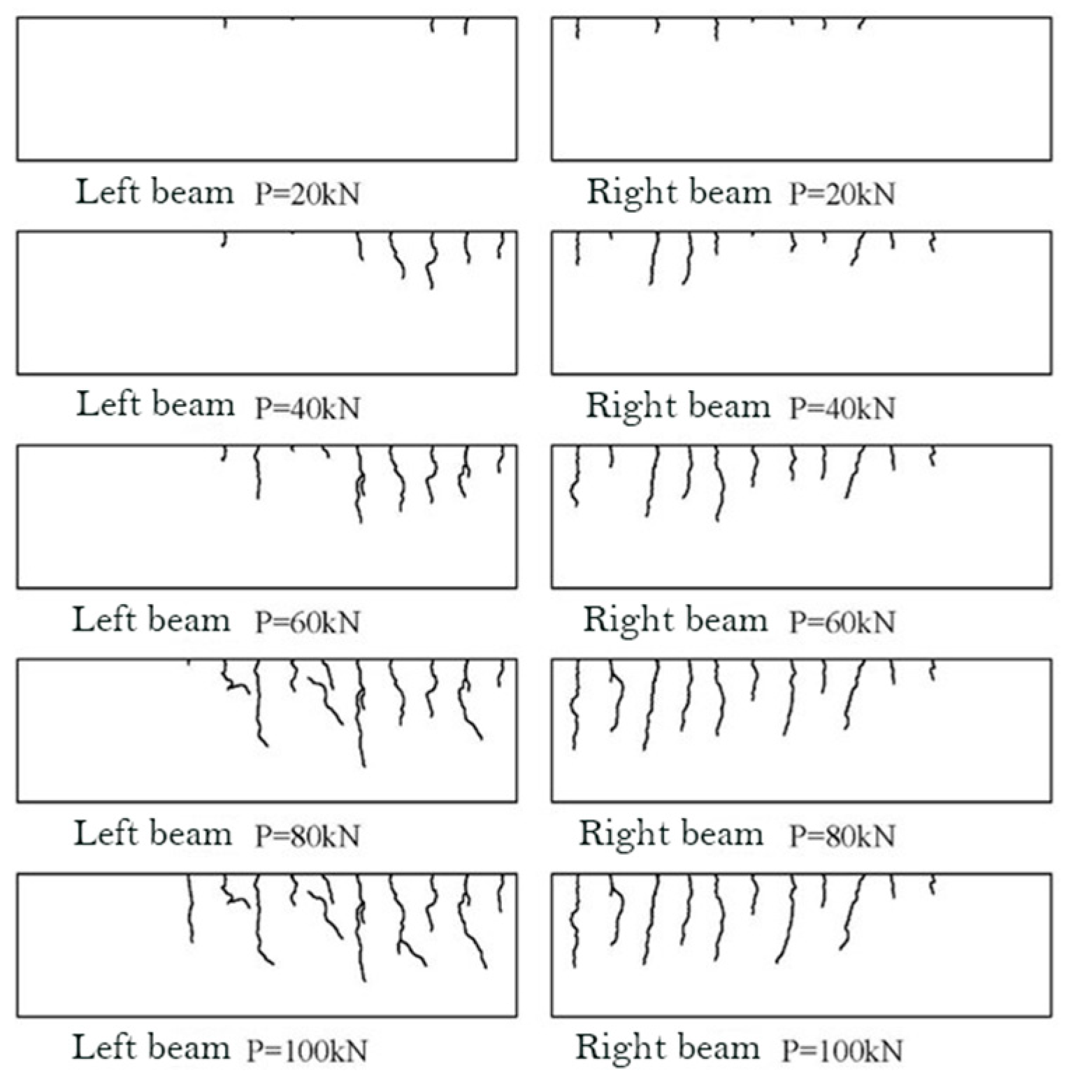
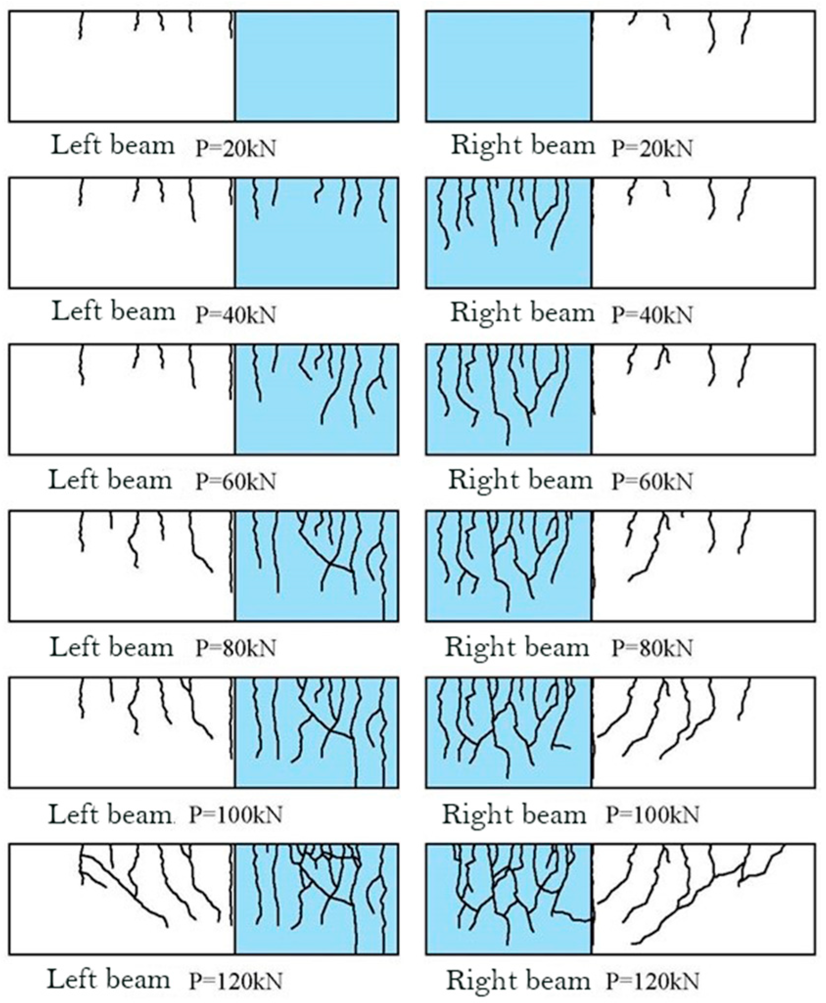
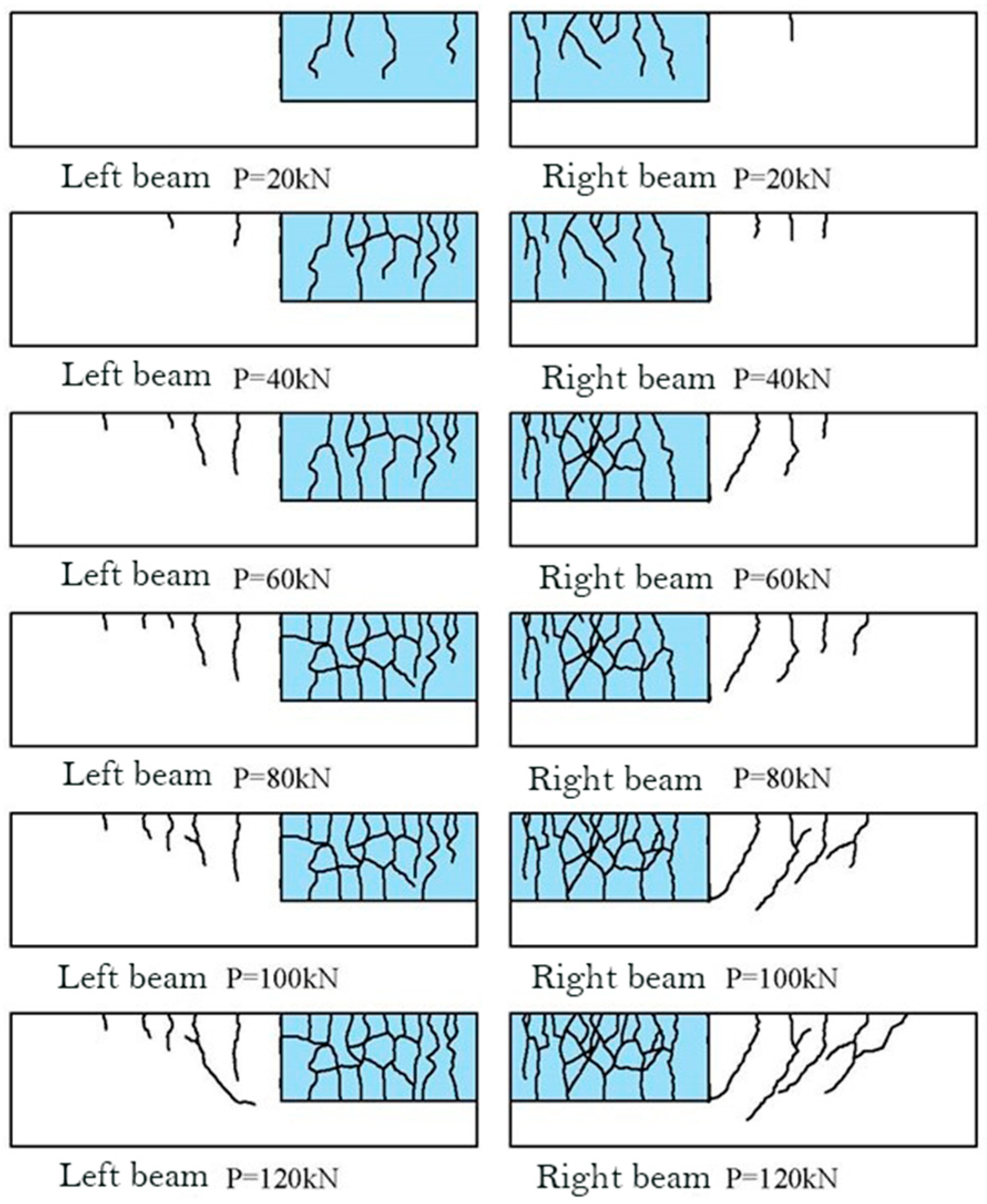
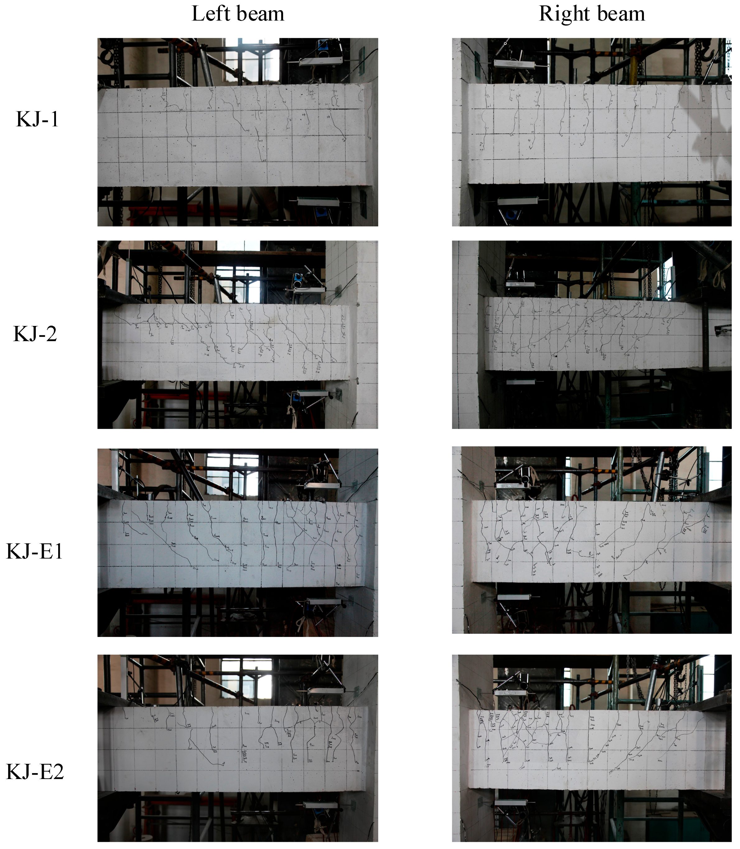
5.1. Development of Cracks
5.2. Crack Spacing
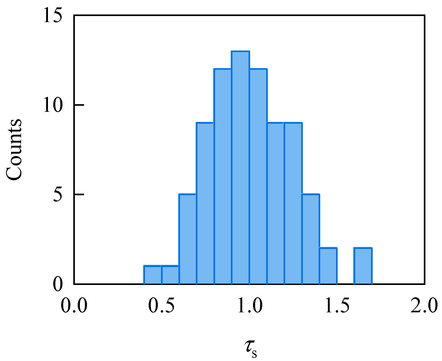
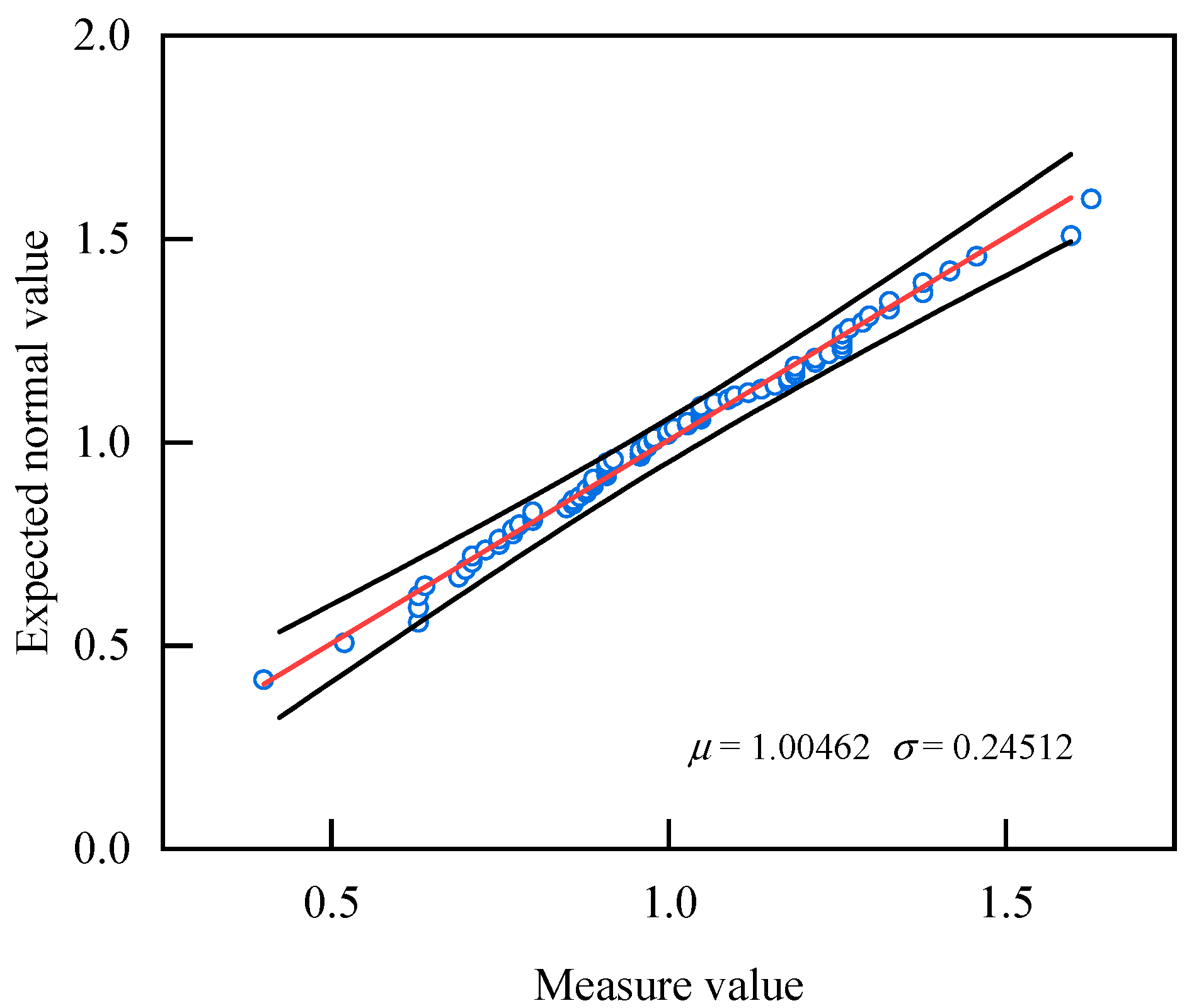
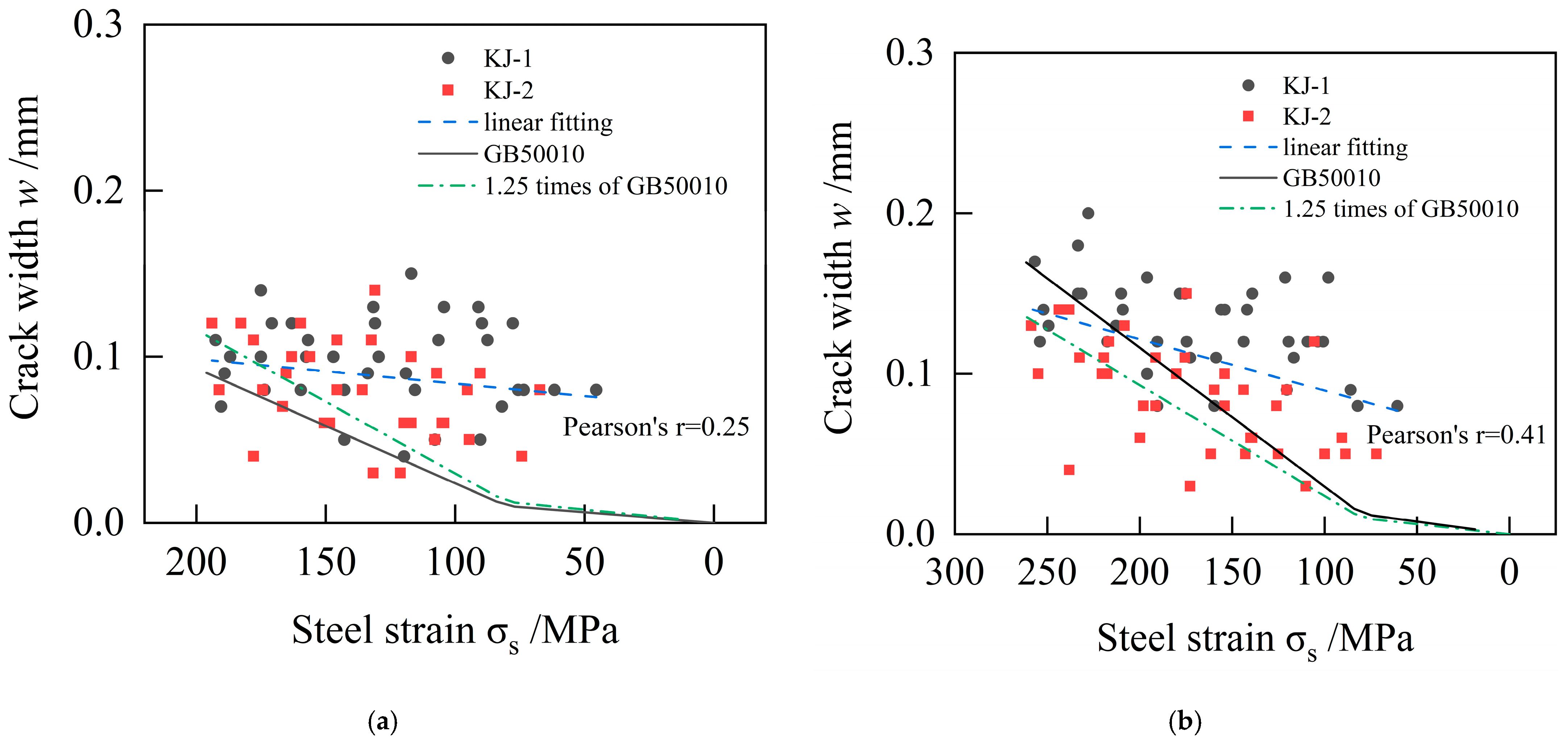
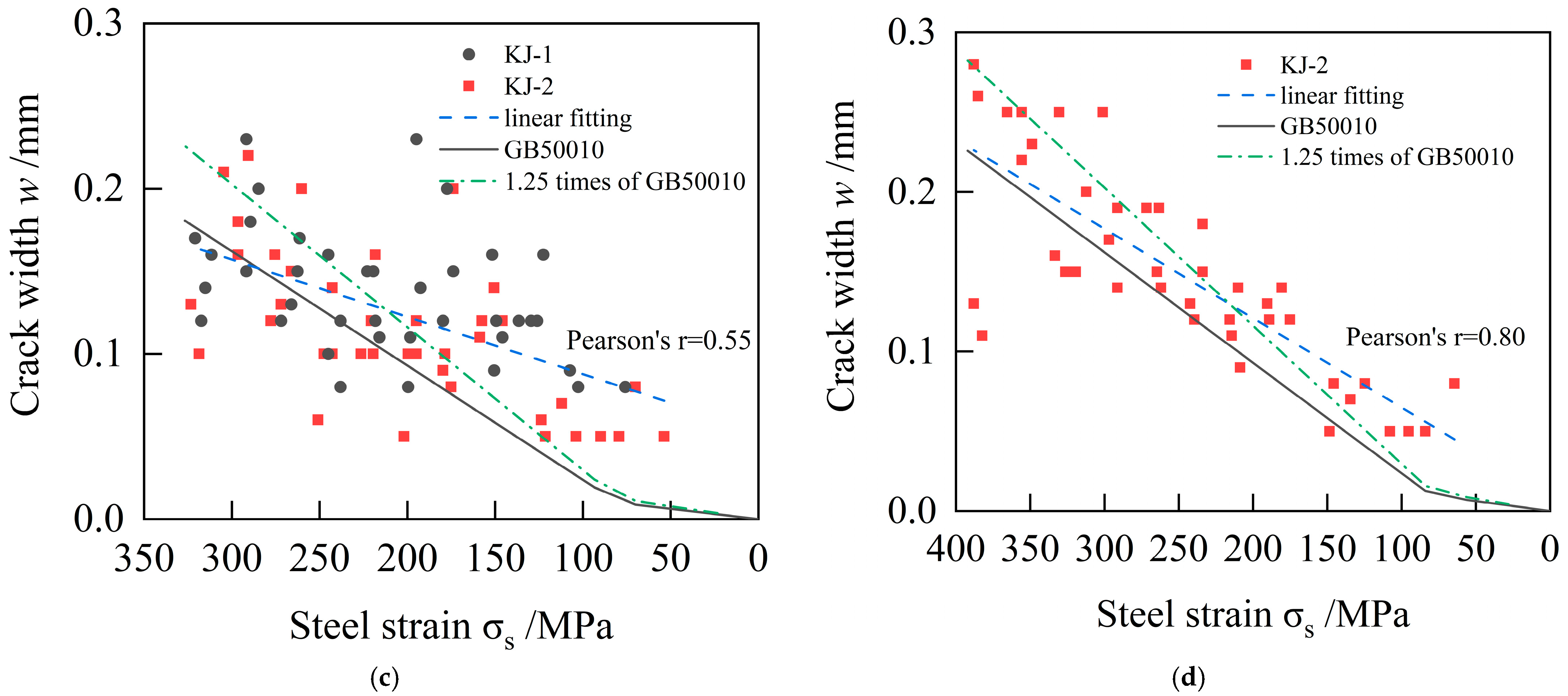
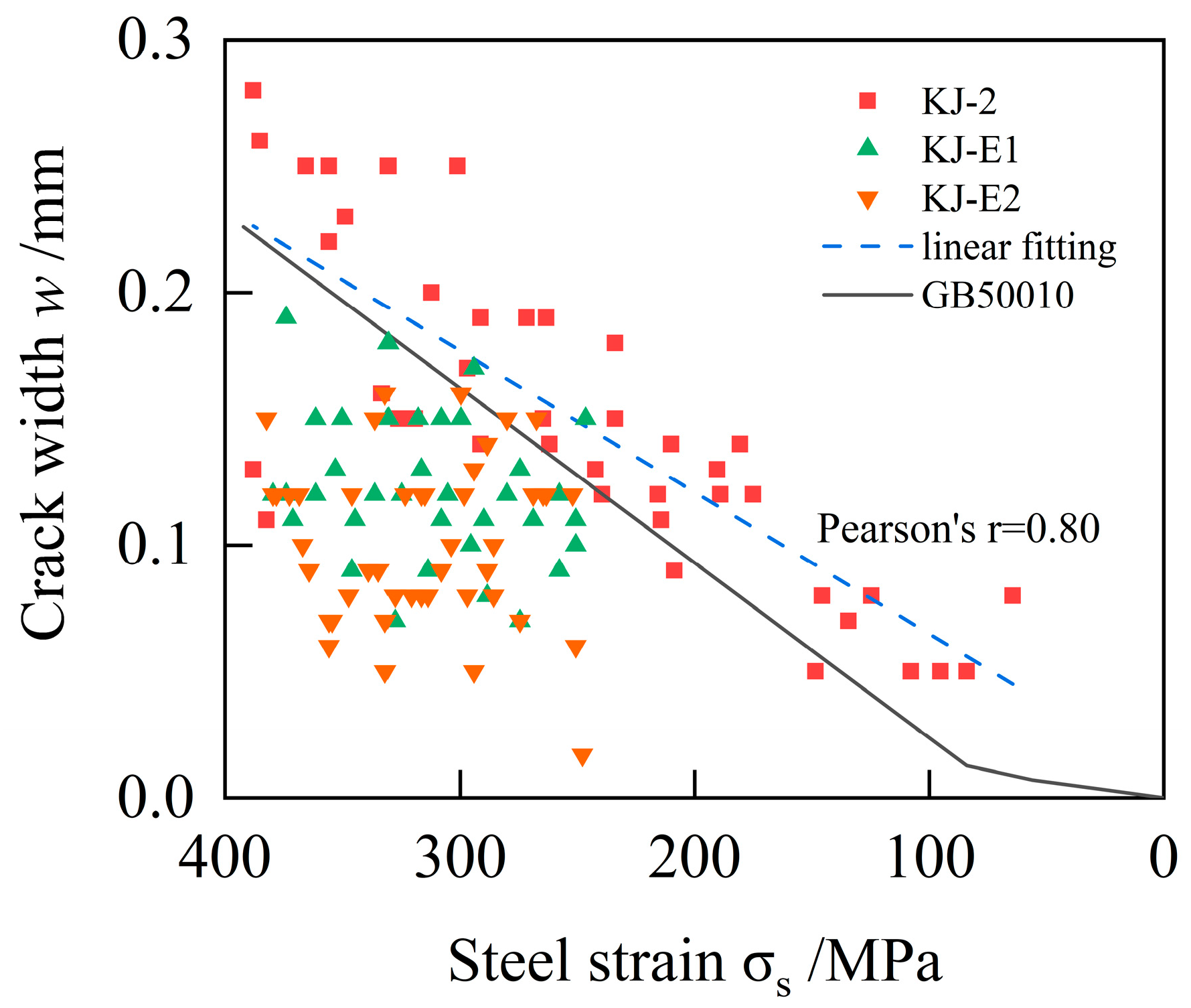
5.3. Crack Width
6. Conclusions
Author Contributions
Funding
Data Availability Statement
Conflicts of Interest
References
- GB50010-2010; Code for Design of Concrete Structures. China Architecture & Building Press: Beijing, China, 2016.
- Zhang, Y.X.; Zhang, S.J.; Deng, M.K. Four-point bending tests of ECC: Mechanical response and toughness evaluation. Case Study Constr. Mater. 2022, 17, e01573. [Google Scholar] [CrossRef]
- Fischer, G.; Li, V.C. Influence of matrix ductility on tension-stiffening behavior of steel reinforced engineered cementitious composites (ECC). ACI Struct. J. 2002, 99, 104–111. [Google Scholar]
- National Technical Measures for Design of Civil Construction RC Structure; China Architecture & Building Press: Beijing, China, 2009.
- Marshall, D.B.; Cox, B.N. A J-integral method for calculating steady-state matrix cracking stresses in composites. Mech. Mater. 1988, 7, 127–133. [Google Scholar] [CrossRef]
- Li, V.C.; Leung, C.K.Y. Theory of steady state and multiple cracking of random discontinuous fiber reinforced brittle matrix composites. ASCE J. Eng. Mech. 1992, 118, 2246–2264. [Google Scholar] [CrossRef]
- Han, T.S.; Feenstra, P.H.; Billington, S.L. Simulation of highly ductile fiber-reinforced cement based composite components under cyclic loading. ACI Struct. J. 2003, 100, 749–757. [Google Scholar]
- Kanakubo, T. Tensile characteristics evaluation method for ductile fiber-reinforced cementitious composites. J. Adv. Concr. Technol. 2006, 4, 3–17. [Google Scholar] [CrossRef]
- Yang, Y.D.; Pu, J.C.; Tian, H.; Deng, J.X. Study on the crack of reinforced concrete beams repaired with ECC during the normal working stage. Build. Sci. 2022, 38, 9–16. [Google Scholar]
- Fischer, G.; Li, V.C. Deformation behavior of fiber-reinforced polymer reinforced engineered cementitious composite (ECC) flexural members under reversed cyclic loading conditions. ACI Struct. J. 2003, 100, 25–35. [Google Scholar]
- Leung, C.K.Y.; Cheung, Y.N.; Zhang, J. Fatigue enhancement of concrete beam with ECC layer. Cem. Concr. Res. 2007, 37, 743–750. [Google Scholar] [CrossRef]
- Hu, Z.H.; Zhou, Y.W.; Hu, B.; Huang, X.X.; Guo, M.H. Local use of ECC to simultaneously enhance the shear strength and deformability of RC beams. Constr. Build. Mater. 2022, 353, 129085. [Google Scholar] [CrossRef]
- Sheng, J.; Yin, S.P.; Yue, J.H.; Yang, Y.H. Bending performance of ECC-RC composite beam reinforced with textile. Constr. Build. Mater. 2021, 287, 123079. [Google Scholar] [CrossRef]
- Cui, T.; He, H.X.; Zhao, X.L.; Zhou, D.X. Bending performance analysis of precast composite beams with precast ECC plate. Structures 2021, 33, 986–998. [Google Scholar] [CrossRef]
- Li, Y.Z.; Li, J.X.; Yang, E.H.; Guan, X.C. Mechanism study of crack propagation in river sand engineered cementitious composites (ECC). Cem. Concr. Compos. 2022, 128, 104434. [Google Scholar] [CrossRef]
- Shoji, D.; He, Z.; Zhang, D.; Li, V.C. The greening of engineered cementitious composites (ECC): A review. Constr. Build. Mater. 2022, 327, 126701. [Google Scholar] [CrossRef]
- Zhang, J.; Wang, Z.B.; Ju, X.C.; Shi, Z.J. Simulation of flexural performance of layered ECC-concrete composite beam with fracture mechanics model. Eng. Fract. Mech. 2014, 131, 419–438. [Google Scholar] [CrossRef]
- Ge, W.J.; Ashour, A.F.; Ji, X.; Cai, C.; Cao, D.F. Flexural behavior of ECC-concrete composite beams reinforced with steel bars. Constr. Build. Mater. 2018, 159, 175–188. [Google Scholar] [CrossRef]
- Tian, J.; Wu, X.W.; Tan, X.; Wang, W.W.; Hu, S.W.; Du, Y.F.; Yuan, J.Y.; Huang, W.T.; Huang, X. Experimental study and analysis model of flexural synergistic effect of reinforced concrete beams strengthened with ECC. Constr. Build. Mater. 2022, 352, 128987. [Google Scholar] [CrossRef]
- Zhu, J.X.; Weng, K.F.; Liu, W.H.; Huang, B.T.; Peng, K.D.; Zhu, J.H.; Dai, J.G. Thin-layer ultra-high-strength engineered cementitious composites (UHS-ECC) reinforced with small-diameter FRP bars for structural strengthening. Thin-Walled Struct. 2024, 205, 112592. [Google Scholar] [CrossRef]
- Zhou, Y.W.; Sui, L.L.; Huang, X.X.; Guo, M.H.; Luo, M.S.; Hu, B.; Chen, C. Enhancing the EB-FRP strengthening effectiveness by incorporating a cracking-control layer of ECC with different thicknesses. Constr. Build. Mater. 2021, 286, 122975. [Google Scholar] [CrossRef]
- Cong, L.Y.; Zhang, F.; Qian, Y.J. Experimental study of flexural behavior of ECC-CFRP composite reinforced beams with different ECC thicknesses. Structures 2024, 66, 106873. [Google Scholar] [CrossRef]
- Wu, Q.W.; You, J.Y.; Wang, H.; Wan, D.B.; Hou, Z.G.; Li, Y.P.; Wang, Y.H.; Chen, X.; Liu, L. Flexural behavior of over-reinforced beam with ECC layer: Experimental and numerical simulation study. Heliyon 2024, 19, e38271. [Google Scholar] [CrossRef]
- Yuan, F.; Pan, J.L.; Xu, Z.; Leung, C.K.Y. A comparison of engineered cementitious composites versus normal concrete in beam-column joints under reversed cyclic loading. Mater. Struct. 2013, 46, 145–159. [Google Scholar] [CrossRef]
- Zhang, R.; Matsumoto, K.; Hirata, T.; Ishizeki, Y.; Niwa, J. Application of PP-ECC in beam-column joint connections of rigid-framed railway bridges to reduce transverse reinforcements. Eng. Struct. 2015, 86, 146–156. [Google Scholar] [CrossRef]
- Qudah, S.; Maalej, M. Application of engineered cementitious composites (ECC) in interior beam-column connections for enhanced seismic resistance. Eng. Struct. 2014, 69, 235–245. [Google Scholar] [CrossRef]
- Said, S.H.; Razak, H.A. Structural behavior of RC engineered cementitious composite (ECC) exterior beam-column joints under reversed cyclic loading. Constr. Build. Mater. 2016, 107, 226–234. [Google Scholar] [CrossRef]
- Shamass, R.; Cashell, K.A. Experimental investigation into the flexural behaviour of basalt FRP reinforced concrete members. Eng. Struct. 2020, 220, 110950. [Google Scholar] [CrossRef]
- Ashtiani, M.S.; Dhakal, R.P.; Scott, A.N. Seismic performance of high-strength self-compacting concrete in reinforced concrete beam-column joints. J. Eng. Struct. 2014, 140, 04014002. [Google Scholar] [CrossRef]
- Li, Y.; Guan, X.; Zhang, C.; Liu, T. Development of high-strength and high- ductility ECC with saturated multiple cracking based on the flaw defect of coarse river sand. J. Mater. Civ. Eng. 2020, 32, 56–63. [Google Scholar] [CrossRef]
- Li, V.C. On engineered cementitious composites (ECC) a review of the material and its applications. J. Adv. Concr. Technol. 2003, 1, 215–230. [Google Scholar] [CrossRef]
- Li, H.D.; Leung, K.C.Y.; Xu, S.L.; Cao, Q. Potential use of strain hardening ECC in permanent formwork with small scale flexural beams. J. Wuhan Univ. Technol.-Mater. Sci. Ed. 2009, 24, 482–487. [Google Scholar] [CrossRef]
- GB/T 50081-2019; Standard for Test Method of Mechanical Properties on Ordinary Concrete. China Architecture & Building Press: Beijing, China, 2019.
- JC/T 2461-2018; Standard Test Method for the Mechanical Properties of Ductile Fiber Reinforced Cementitious Composites. Ministry of Industry and Information Technology of the People’s Republic of China: Beijing, China, 2018.
- GB/T 228.1-2021; Metallic Materials-Tensile Testing-Part 1: Method of Test at Room Temperature. Standards Press of China: Beijing, China, 2021.
- GB/T 50152-2012; Standard for Test Method of Concrete Structures. China Architecture & Building Press: Beijing, China, 2012.
- Li, V.C.; Mishra, D.K.; Naaman, A.E.; Wight, J.K.; LaFave, J.M.; Wu, H.-C.; Inada, Y. On the shear behavior of engineered cementitious composites. Adv. Cem. Based Mater. 2003, 1, 142–149. [Google Scholar] [CrossRef]
- Pan, Z.F.; Wu, C.; Liu, J.Z.; Wang, W.; Liu, J.W. Study on mechanical properties of cost-effective polyvinyl alcohol engineered cementitious composites (PVA-ECC). Constr. Build. Mater. 2015, 78, 397–404. [Google Scholar] [CrossRef]


| Specimen Number | fcu/MPa | fc/MPa | ft/MPa | Ec/MPa |
|---|---|---|---|---|
| KJ-1, KJ-2 | 45.01 | 34.21 | 3.21 | 33,660.2 |
| KJ-E1, KJ-E2 | 46.08 | 35.02 | 3.25 | 33,864.4 |
| Specimen Number | f1 /MPa | f2 /MPa | ft /MPa | fc /MPa | fcu /MPa |
|---|---|---|---|---|---|
| KJ-E1, KJ-E2 | 18.32 | 8.54 | 6.0 | 43.09 | 56.70 |
| Diameter/mm | Cross-Sectional Area/mm2 | fy/MPa | fu/MPa | δ/% |
|---|---|---|---|---|
| 6 | 28.86 | 435.67 | 658.77 | 13.7 |
| 8 | 49.24 | 412.77 | 653.30 | 14.7 |
| 10 | 76.38 | 418.55 | 657.32 | 14.7 |
| 12 | 100.51 | 491.68 | 675.90 | 16.7 |
| 14 | 139.84 | 445.80 | 632.48 | 21.0 |
| 18 | 233.28 | 487.69 | 700.01 | 20.3 |
| 20 | 288.89 | 489.07 | 690.78 | 22.3 |
| Load P/kN | Expansion Coefficient of Short-Term Crack Width/Average Crack Width | |||||||||||||||
|---|---|---|---|---|---|---|---|---|---|---|---|---|---|---|---|---|
| Crack 1 | Crack 2 | Crack 3 | Crack 4 | |||||||||||||
| E-N | E-S | W-N | W-S | E-N | E-S | W-N | W-S | E-N | E-S | W-N | W-S | E-N | E-S | W-N | W-S | |
| 40 | 1.60 | 0.80 | 0.96 | 0.64 | 0.40 | 1.19 | 1.19 | 1.63 | 0.97 | 1.24 | 1.10 | 0.69 | 1.26 | 1.05 | 1.05 | 0.63 |
| 60 | 1.30 | 0.86 | 0.86 | 0.97 | 0.80 | 0.91 | 1.03 | 1.26 | 1.26 | 1.05 | 1.05 | 0.63 | 1.42 | 0.77 | 1.03 | 0.77 |
| 80 | 1.27 | 0.91 | 0.91 | 0.91 | 0.96 | 0.96 | 0.87 | 1.22 | 1.07 | 0.89 | 1.16 | 0.89 | 1.00 | 0.73 | 1.18 | 1.09 |
| 100 | 1.33 | 0.63 | 0.89 | 1.14 | 0.75 | 1.38 | 0.88 | 1.00 | 0.92 | 0.80 | 1.29 | 0.98 | 0.98 | 0.70 | 1.05 | 1.26 |
| 120 | 1.18 | 0.52 | 0.85 | 1.46 | 0.78 | 1.12 | 0.88 | 1.22 | 0.71 | 0.71 | 1.38 | 1.19 | 0.75 | 0.91 | 1.01 | 1.33 |
Disclaimer/Publisher’s Note: The statements, opinions and data contained in all publications are solely those of the individual author(s) and contributor(s) and not of MDPI and/or the editor(s). MDPI and/or the editor(s) disclaim responsibility for any injury to people or property resulting from any ideas, methods, instructions or products referred to in the content. |
© 2025 by the authors. Licensee MDPI, Basel, Switzerland. This article is an open access article distributed under the terms and conditions of the Creative Commons Attribution (CC BY) license (https://creativecommons.org/licenses/by/4.0/).
Share and Cite
Yang, Y.; Yang, H.; Jiang, Z.; Mu, Z. Study on Crack Development of Frame Beams with U-Shaped Engineered Cementitious Composites Cover Layer Under Negative Moments. Appl. Sci. 2025, 15, 5397. https://doi.org/10.3390/app15105397
Yang Y, Yang H, Jiang Z, Mu Z. Study on Crack Development of Frame Beams with U-Shaped Engineered Cementitious Composites Cover Layer Under Negative Moments. Applied Sciences. 2025; 15(10):5397. https://doi.org/10.3390/app15105397
Chicago/Turabian StyleYang, Yuqing, Hongyue Yang, Zhelong Jiang, and Zaigen Mu. 2025. "Study on Crack Development of Frame Beams with U-Shaped Engineered Cementitious Composites Cover Layer Under Negative Moments" Applied Sciences 15, no. 10: 5397. https://doi.org/10.3390/app15105397
APA StyleYang, Y., Yang, H., Jiang, Z., & Mu, Z. (2025). Study on Crack Development of Frame Beams with U-Shaped Engineered Cementitious Composites Cover Layer Under Negative Moments. Applied Sciences, 15(10), 5397. https://doi.org/10.3390/app15105397