1. Introduction
The growing global environmental awareness and depletion of fossil fuel reserves have heightened interest in renewable energy sources [
1,
2]. However, renewable power generation faces several challenges [
3,
4,
5,
6,
7]. Firstly, the power generated by renewable energy sources demonstrates random, intermittent, and fluctuating outputs that pose substantial challenges to grid stability. Secondly, heavy reliance on power electronic equipment leads to lower system inertia and insufficient grid voltage and frequency regulation support. Lastly, the uneven distribution of renewable energy stations and load centers results in long transmission distances and substantial losses. To address these challenges, integrating energy storage into the power system is often necessary.
The supercapacitor energy storage system (SCES) provides several advantages over batteries, such as rapid charging, high power density, and environmental sustainability. These characteristics render it a practical, efficient, and environmentally friendly energy storage solution that can smooth power fluctuations, enhance power quality, and facilitate renewable energy integration [
8]. In medium- and high-voltage transmission systems, the modular multilevel converter (MMC) is characterized by high modularity, low harmonic distortion, and negligible losses [
9]. The integration of supercapacitors into each MMC submodule forms the MMC-SCES system. This system demonstrates robust fault tolerance, flexible control, and notable advantages for renewable energy grid integration and high-voltage direct-current (HVDC) transmission [
10,
11].
To leverage the modularity of the MMC, supercapacitors can be integrated with each submodule through three distinct approaches: direct parallel connection [
12,
13], parallel connection via a bidirectional DC/DC converter [
14,
15,
16], and parallel connection through an isolated DC/DC converter [
17,
18]. The first topology offers simplicity and relatively low power losses. However, this approach directly exposes the supercapacitor to second-harmonic power, necessitating large submodule capacitors for mitigation [
19]. To preserve the supercapacitor’s lifespan, a bidirectional DC/DC converter serves as an intermediate stage [
20]. The DC/DC converter decouples the supercapacitor from the submodule capacitor, enhancing system flexibility while enabling active charge/discharge management. A notable limitation is the reduction in overall energy conversion efficiency introduced by the DC/DC converter. The isolated topology provides essential insulation between submodules in high-voltage applications while ensuring electrical isolation for safety. However, it requires additional switching devices, increasing the system complexity and cost [
21]. Considering both functionality and practicality, this paper adopts the second topology.
The MMC-SCES consists of multiple energy storage modules (ESMs) connected in series. Inherent parameter variations among supercapacitors lead to state-of-charge (SOC) discrepancies across ESMs. The ESM with the minimum SOC determines the system’s maximum utilizable energy storage capacity. Consequently, SOC balancing among ESMs becomes essential for optimal system performance.
One effective approach to balance SOC within an arm is to sort the SOCs of all submodules [
14]. However, the computational complexity escalates substantially with the increasing number of submodules. While the zero-sequence voltage injection method achieves SOC balancing among different phases, its implementation demands sophisticated mathematical computations and, consequently, more advanced control hardware [
20,
22]. A simpler closed-loop method can balance SOC among submodules within an arm and phases but does not address SOC imbalances between the upper and lower arms [
23]. To overcome these limitations, a three-level proportional controller employing circulating current injection has been proposed for SOC balancing under carrier phase-shifted pulse width modulation (CPS-PWM). The balancing speed exhibits direct proportionality to the coefficient [
24,
25,
26]. Furthermore, an adaptive SOC coefficient strategy has been developed to accelerate the balancing process [
27,
28]. However, CPS-PWM proves unsuitable for high-voltage applications, as the modulation complexity grows substantially with increasing voltage levels. In contrast, artificial intelligence (AI)-based SOC balancing strategies, including model predictive control [
29,
30], multi-agent systems [
31], fuzzy logic control [
32,
33], and reinforcement learning [
34,
35], have offered scalable solutions to high-voltage challenges. Distributed control methods, such as multi-agent-based strategies and predictive power model-based strategies, have successfully achieved SOC balancing in HVDC transmission systems [
29,
31]. However, these algorithms impose excessive computational demands due to their dependence on iterative optimization and real-time data processing. This poses critical implementation challenges, as industrial-grade embedded systems lack the computational capacity to support such intensive real-time computations without compromising system responsiveness. Additionally, most of these SOC balancing strategies primarily focus on submodules, necessitating controllers with a matching number of bidirectional DC/DC converters as the ESM. However, MMC-SCES is often utilized in high-voltage applications, leading to substantial computational demands and increased system complexity.
To overcome the limitations of existing strategies, this paper analyzes the correlation between supercapacitor SOC and submodule capacitor voltage. An enhanced SOC balancing control strategy is proposed to equalize the supercapacitor SOC through phase SOC balancing, arm SOC balancing, and capacitor voltage balancing regulation. Finally, a two-terminal transmission system with MMC-SCES is built in PSCAD/EMTDC to verify the feasibility and effectiveness of the proposed strategy.
The paper is organized as follows:
Section 2 presents the topology and operating principle of MMC-SCES.
Section 3 introduces the balancing principle and the three-level SOC balance control in detail.
Section 4 simulates and compares the proposed SOC balancing strategy and the traditional one. Finally, conclusions are drawn in
Section 5.
2. Converter Structure and Operation Principle
2.1. Topology Description
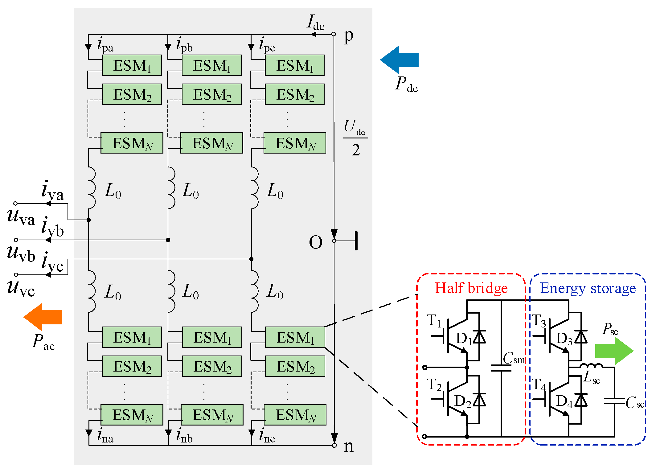
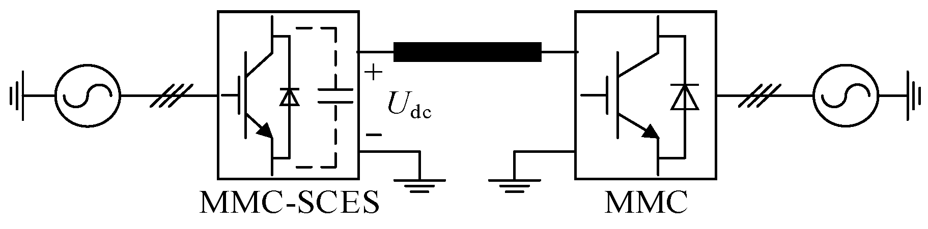
As depicted in
Figure 1, the main circuit topology of MMC-SCES closely resembles that of traditional MMC. It comprises three parallel-connected phase units. Each phase unit consists of two arms, formed by a series connection of
N ESMs and the arm inductance
L0. In this configuration,
Udc represents the DC bus voltage,
ipj and
inj are the currents of the upper and lower arms of phase
j, respectively (where
j = a, b, c), while
uvj and
ivj denote the phase
j equivalent output voltage and current of the AC side.
The ESM consists of a half-bridge submodule section and an energy storage section. The half-bridge submodule includes two switches, T1 and T2, and a capacitor Csm, which operates similarly to a conventional half-bridge submodule in MMC. When switch T1 is turned on and T2 is off, the cell is inserted. Conversely, when T1 is off and T2 is on, the cell is bypassed. The energy storage section incorporates a bidirectional DC/DC converter, formed by switches T3 and T4, together with inductor Lsc, which interfaces the supercapacitor Csc with the main circuit. The bidirectional DC/DC converter enables a significant reduction in the voltage rating requirements for the energy storage system. The operating mode of the supercapacitor is governed by the switching devices of the energy storage section. When switch T3 is turned on and T4 is off, the converter operates in Buck mode, charging the supercapacitor. Conversely, when T3 is turned off and T4 is on, it operates in Boost mode, discharging the supercapacitor.
Complementary firing pulses are applied to switches T3 and T4. Assuming that the on-time of the switch T3 is Ton and the off-time is Toff, then Ton + Toff = T.
When switch T
3 is turned on and T
4 is off, according to Kirchhoff’s voltage law (KVL), it can be stated as:
where
UL is the voltage of the inductor in the energy storage,
Usc is the supercapacitor voltage, and
Usm is the submodule capacitor voltage.
When switch T
3 is turned off and T
4 is on, according to KVL, it can be stated as:
At steady state, the following equation can be derived from inductor volt-second balance:
Consequently, the duty cycle of switch T
3 can be derived as:
The supercapacitor voltage exhibits direct proportionality to the submodule capacitor voltage, with the scaling factor governed by the duty cycle d of switch T3.
2.2. Power Flow Analysis
The power flow directions are schematically illustrated in
Figure 1. Neglecting losses, a portion of the DC power is transferred to the AC link, while the remainder is exchanged with the supercapacitor energy storage system. The power relationship can be expressed as:
where
Psc represents the total energy storage power of all ESMs in the MMC-SCES, denoted as:
The MMC-SCES operates as a three-port power conversion system, connected to the AC grid, the DC system, and the supercapacitor energy storage system. It can simultaneously perform energy storage and AC–DC conversion functions.
Neglecting the effect of the inductor, the voltages for the upper and lower arms of each phase in the MMC-SCES are given by:
In the MMC-SCES, the second- and higher-order harmonic components of the circulating current do not affect the active power transmission. Consequently, the analysis considers only the DC component and fundamental frequency component of the circulating current, which can be mathematically expressed as:
where
Idcj is the DC component of the circulating current, and
I1j and
θj are the amplitude and phase of the fundamental component of the circulating current, respectively.
Assuming symmetrical arm impedances, the AC current divides equally between the upper and lower arms within each phase unit. The arm currents can be defined as:
where φ is the power factor angle.
By multiplying Equations (7) and (9), the average power of the upper arm, lower arm, and entire phase can be obtained, as expressed by:
Under steady-state conditions, capacitor voltage stability requires the submodule capacitor to absorb equal average power from both the MMC and supercapacitor energy storage system. This power balance ensures that the average power in each arm equals the total supercapacitor power for that arm, and the average power per phase matches the total supercapacitor power within the respective phase:
In a three-phase balanced operation, the power of each phase is affected by the DC component of the circulating current. Supercapacitor energy storage system power imbalances within phases induce corresponding imbalances in this DC circulating current component. Additionally, the power of arms is affected by the fundamental component of the circulating current, which has an opposite influence on the upper and lower arm powers. If a power difference exists between the supercapacitors in the upper and lower arms, a fundamental component of the circulating current will arise in that phase. Therefore, by adjusting the supercapacitor power of the phases and arms, it is possible to control the DC component and fundamental component of circulating currents, thus achieving SOC balancing between phases and arms. This is the principle of the SOC balancing control strategy discussed in the following sections.
2.3. Control Strategy
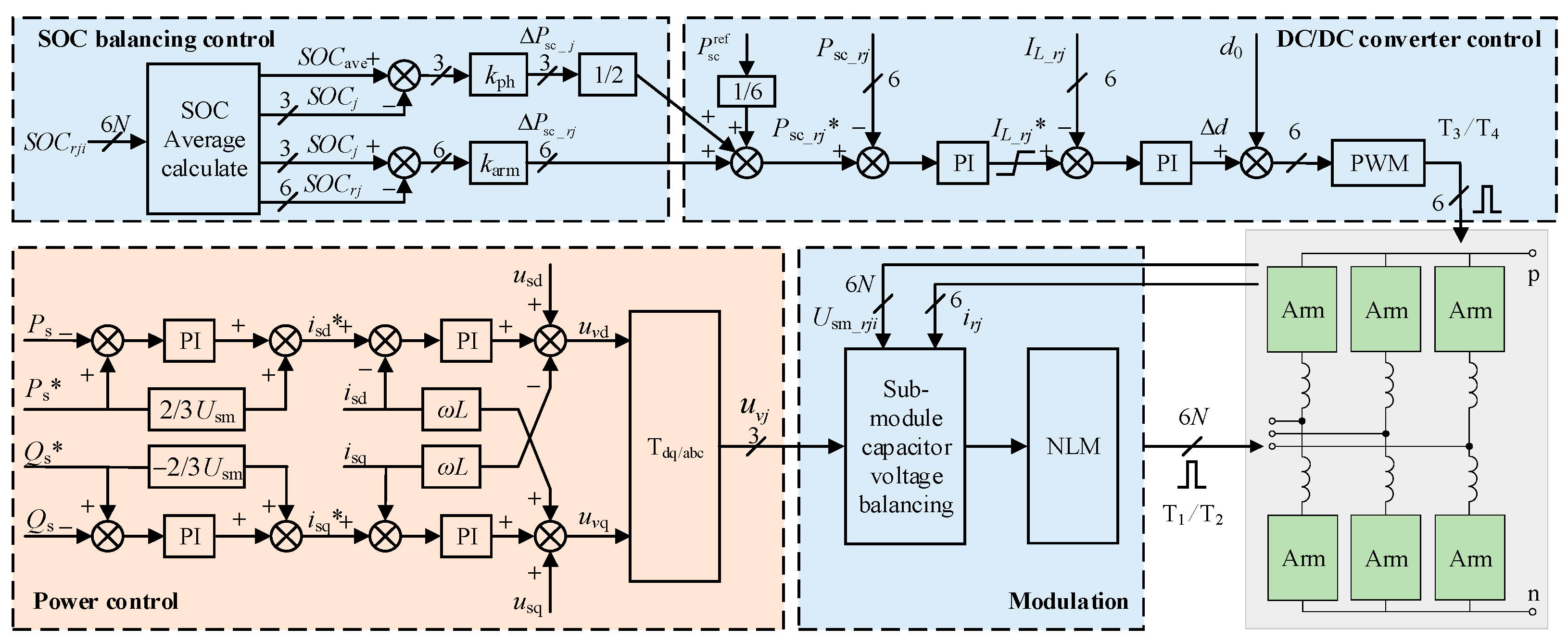
The overall control block diagram is shown in
Figure 2, consisting of four parts: power control, DC/DC converter control, SOC balancing control, and modulation.
The integration of supercapacitors into each submodule via a bidirectional DC/DC converter enables the MMC-SCES to maintain the characteristic AC and DC port behavior of the conventional MMC. This similarity preserves the effectiveness of the dual-loop power control strategy. The outer active and reactive power loops establish the reference values for the d-axis and q-axis currents, while the inner current loop implements decoupling control to generate the modulated voltage. Through dq/abc coordinate transformation, the system ultimately produces the desired phase-modulated output voltage uvj.
The bidirectional DC/DC converters employ a dual closed-loop control strategy to optimize supercapacitor performance and extend operational lifespan. This strategy consists of two main control loops: an outer power loop and an inner current loop. The outer loop maintains the supercapacitor power reference, while the inner loop controls the energy storage current. A feedforward duty cycle is utilized to enhance system tracking performance. The feedforward duty cycle is calculated as the ratio of the supercapacitor rated voltage to the submodule capacitor rated voltage, while the dual-loop control compensates for steady-state errors. Current constraints are implemented to prevent supercapacitor overcharging and over-discharging conditions.
To minimize hardware complexity, this paper proposes a centralized control strategy where all ESMs per arm share a common energy storage controller. This ensures consistent duty cycles across all ESMs in the arm. Compared to the traditional SOC balancing strategy, the centralized control strategy fundamentally modifies the generation of gate signals for the bidirectional DC/DC converters. This achieves an N times reduction in controllers, dramatically simplifying the control architecture while maintaining balancing performance.
The SOC balancing control strategy is introduced in detail in the following section.
3. SOC Balancing
During the operation of MMC-SCES, the SOC difference may gradually increase due to the slight difference between supercapacitors. This will decrease the capacity utilization efficiency of the supercapacitors. Therefore, SOC balancing control is essential.
SOC is a critical parameter for evaluating the health and longevity of supercapacitors. It quantifies the electric charge remaining in the device relative to its fully charged state. It also denotes the ratio of the remaining electrical energy to the fully charged state, which can be expressed as:
where
Qre and
Wre are the remaining electric charge and electrical energy of the supercapacitor, and
Qn and
Wn are the electric charge and electrical energy when the supercapacitor is fully charged.
3.1. Balancing Principle
The relationship between the total electrical energy
Wtotsc of supercapacitor
Csc and its terminal voltage
Usc can be expressed as:
In reality, the usable energy
Wsc of the supercapacitor is only a fraction of
Wtotsc, and it depends on the maximum
Umaxsc and minimum
Uminsc allowable terminal voltage [
8]:
Assuming the minimum allowable terminal voltage of the supercapacitor is half of its rated voltage, and the maximum allowable voltage is rated voltage, then the SOC can be expressed as:
where
Uscn represents the rated voltage of the supercapacitor. It is evident that the SOC of the ESM is positively correlated with its terminal voltage.
According to Equation (4), the supercapacitor terminal voltage is directly proportional to the submodule capacitor voltage, with the scaling factor being the duty cycle
d of the switch T
3. Substituting Equation (4) into Equation (15), the SOC can be rewritten as:
The SOC of the ESM is related to both the submodule capacitor voltage and the duty cycle of switch T3. When implementing the centralized control strategy, the duty cycle of switch T3 in each ESM is identical. Consequently, the SOC of each ESM in the arm becomes directly proportional to its corresponding submodule capacitor voltage. This fundamental relationship enables supercapacitor SOC balancing through submodule capacitor voltage control, forming the theoretical foundation for the balancing control strategy proposed in subsequent sections
3.2. SOC Balancing Control Strategy
SOC imbalance among ESMs presents a critical challenge to system operational stability and performance. Traditional balancing approaches often require numerous controllers and exhibit high computational complexity, limiting the practical implementation. To overcome these limitations, this paper proposes an enhanced SOC balancing strategy based on a three-level control system involving phase units, arms, and submodules.
The system implements adaptive power allocation during both charge and discharge states. During discharge, ESMs with higher SOC are allowed to deliver more power, while during charging, those with lower SOC are allowed to absorb more power. Additionally, the SOC imbalances in ESMs per arm through direct regulation of submodule capacitor voltages capitalize on the proportional relationship between supercapacitor SOC and submodule capacitor voltage. By assigning distinct power references to each arm and exploiting the voltage–SOC correlation principle, the enhanced control strategy ensures SOC convergence across all ESMs:
As shown in Equation (17), SSOC_rji is the SOC of the ith ESM in either the upper arm or lower arm of the j phase. Additionally, SSOC_rj and SSOC_j are defined as the average SOC values of the submodules in the arm and the phase, respectively. SSOC_ave is the average SOC value of the entire MMC-SCES.
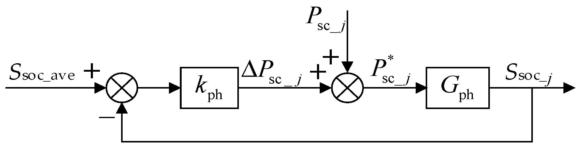
SOC imbalances among phases can be effectively addressed through controlled injection of unbalanced power.
Figure 3 illustrates the proposed control for SOC balancing among phases.
kph represents the proportional coefficient for phase balancing, and
Gph is the transfer function relating phase energy storage power to the average SOC. The control calculates the deviation between each phase’s average SOC and the system mean value, then generates phase unbalanced power through proportional control. The unbalanced power is superimposed on the nominal phase powers while rigorously maintaining the zero-sum constraint across all phases. The power adjustments in each phase’s supercapacitors induce corresponding variations in the submodule capacitor voltages. This results in the DC circulating currents being actively redistributed among phases.
The arm SOC balancing control strategy ensures uniform SOC values between the upper and lower arm within each phase through dynamic power allocation. As illustrated in
Figure 4, the proportional coefficient
karm and transfer function G
arm regulate the SOC balancing between arms. The unbalanced power is proportional to the SOC difference between the corresponding upper and lower arms. These power adjustments follow the principle that arms with higher SOC deliver increased power during discharge while receiving reduced power during charge states. The resulting power differential between the upper and lower arms induces fundamental frequency circulating currents. Similarly, the sum of the unbalanced power of the upper and lower arm within each phase is zero. Thus, injecting unbalanced power into the arms does not affect the total energy storage power of the system.
The submodule SOC balancing control maintains uniform SOC values among ESMs within the same arm through the regulation of submodule capacitor voltage. As shown in Equation (16), when the duty cycle of switch T3 in each ESM is identical, the SOC of each ESM exhibits a direct proportional relationship with its corresponding submodule capacitor voltage. This intrinsic correlation enables automatic SOC balancing through conventional capacitor voltage regulation when all ESMs within an arm share a common controller, eliminating the need for additional SOC balancing control.
Submodule capacitor voltage balancing is typically achieved by a real-time sorting algorithm [
36]. This strategy determines the operational states of ESMs based on both capacitor voltage and arm currents’ direction. During the discharging state, ESMs with higher submodule capacitor voltages are preferentially for insertion, while those with lower voltages are bypassed. Conversely, in the charging state, the opposite action is taken. However, the balancing algorithm is applied unconditionally to every control cycle of the arm, and the gate signals are updated at the sampling control frequency. This process results in redundant switching operations, even when the total number of inserting ESMs in one arm remains constant.
High switching frequencies create significant power losses as heat, lowering system efficiency and requiring longer balancing times. More critically, these continuous losses increase operating temperatures, accelerating aging in both power devices and supercapacitor energy storage systems [
37,
38]. The rapid switching also generates damaging electrical stresses on IGBTs. Cumulative stress leads to gradual performance degradation or failure, impairing both the SOC balancing accuracy and system responsiveness [
39,
40]. Ultimately, these combined effects exacerbate SOC imbalances and significantly shorten the system’s operational lifespan.
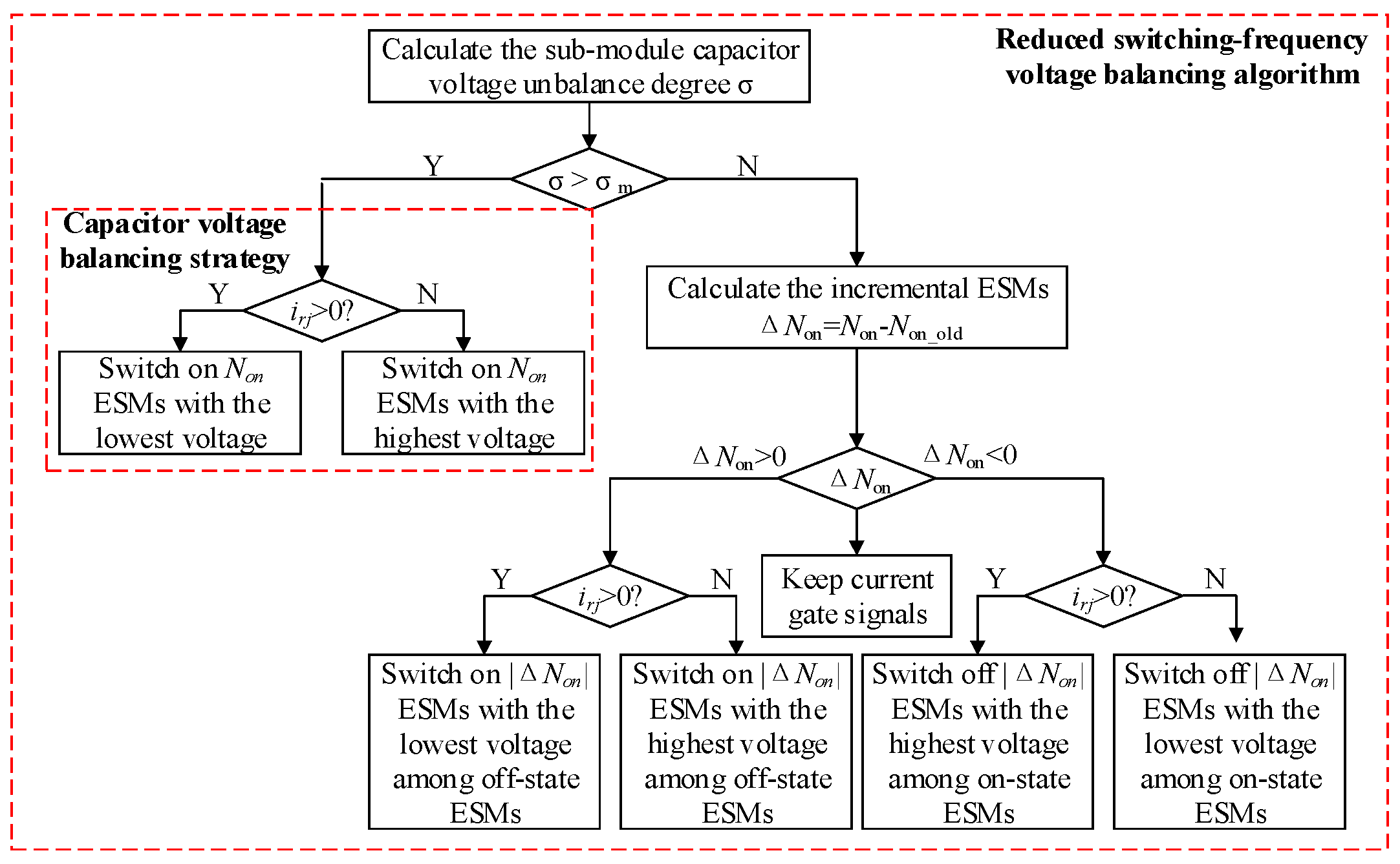
To address this issue, a reduced switching-frequency (RSF) voltage balancing algorithm is proposed [
41].
Figure 5 illustrates both the conventional submodule capacitor voltage balancing algorithm and the RSF algorithm. In contrast to the conventional algorithm, the RSF voltage balancing algorithm introduces the concept of the submodule capacitor voltage unbalance degree σ, defined as the ratio of the maximum voltage deviation among submodules to the rated capacitor voltage. When the submodule capacitor voltage unbalance degree exceeds the threshold value σ
m, all submodule capacitor voltages are sorted. Otherwise, only the incremental ESMs are sorted according to their capacitor voltages.
The capacitor voltage balancing control strategy capitalizes on the operational flexibility of the submodule insertion number to regulate charging and discharging durations. This dynamic voltage regulation inherently enables SOC balancing among all ESMs within each arm by exploiting the voltage–SOC correlation. In contrast to the traditional strategy requiring N independent controllers per arm, the proposed strategy achieves equivalent balancing performance with only six centralized controllers. This represents an N times reduction in controller hardware while maintaining equivalent voltage and SOC regulation performance.
In summary, the final power command for the ESMs in each arm is shown in Equation (18):
where
is the power command before SOC balancing is applied.
3.3. Parameter Design
The proportional coefficients kph and karm critically influence the SOC balancing speed across phases and arms. Increasing the proportional coefficient accelerates the balancing speed. Theoretically, the SOC balancing speed should be maximized to ensure optimal performance. However, with a constant proportional coefficient, the balancing speed declines sharply as the SOC converges. Employing a larger proportional coefficient to reduce the balancing time may inject excessive unbalanced circulating current into the system. This current may exceed the switches’ peak current rating, compromising system operation. To address this issue, this paper proposes an adaptive proportional coefficient-based SOC balancing strategy.
First, the phase balancing variance
dph and the arm balancing variance
darm are calculated separately to quantify the SOC consistency, as expressed in the following equations:
Next, the adaptive coefficient
f(
d) is formulated by jointly considering the SOC balancing speed and the switches’ safe operating range. This function determines the adaptive proportional coefficients for phase and arm SOC balancing, as defined below:
where
a and
b are the scaling factors. To prevent excessive circulating current at the initial time,
a and
b are constrained within the range of 0 to 1.
kph0 and
karm0 are the initial constant proportional coefficients, while
dph0 and
dph0 are the initial balancing variances of phases and arms, respectively.
With the adaptive coefficient, the proportional coefficients for both phase and arm SOC balancing increase during SOC convergence. This adaptation maintains rapid balancing speeds, consequently reducing the total balancing time. Additionally, the scaling factor constrains initial circulating currents, avoiding adverse impacts on system stability.
3.4. SOC Balancing Control with Different Capacitance
As the cycle count accumulates, supercapacitor capacitance inevitably differs due to aging effects. To maintain optimal system performance under these conditions, the power allocation strategy must consider remaining capacity as a critical factor, adjusting power in proportion to each supercapacitor’s remaining capacity.
The total capacitance of supercapacitors in the arm
Csc_rj, the total capacitance of the phase
Csc_j, and the total system capacitance across all three phases C
sc_tot are defined as:
The reference power for supercapacitors is determined through remaining capacity at both the phase and arm, expressed as:
Under conditions of non-uniform supercapacitor capacitance distribution caused by aging, the power command for ESMs in each arm is determined by:
In this case, submodule SOC balancing can also be achieved through the regulation of submodule capacitor voltage. This is because the supercapacitor SOC is determined solely by its rated voltage and actual voltage. Even when the capacitance value is affected by the aging of the supercapacitor, the relationship between SOC and voltage remains valid. Consequently, the strategy proposed in this paper remains effective in achieving SOC balance even under capacitance variations.
4. Simulation
To verify the feasibility and effectiveness of the proposed SOC balancing control strategy, a two-terminal MMC-SCES transmission system was built in PSCAD/EMTDC using the efficient simulation method [
42]. The system architecture is depicted in
Figure 6. Active and reactive power control were applied to the MMC-SCES, while DC voltage and reactive power control were employed on the MMC. Additionally, a conventional circulating current suppression controller (CCSC) was implemented to mitigate the double-line-frequency circulating current within the system [
41]. The system parameters are provided in
Table 1. Furthermore, the traditional balancing method was utilized for comparison [
24].
4.1. SOC Balancing Control with Constant Proportional Coefficients
The SOC of all ESMs was initialized between 50% and 60%. During system operation, the supercapacitor energy storage system maintained a constant 100 MW discharge power, with the SOC balancing control activated at
t = 2 s.
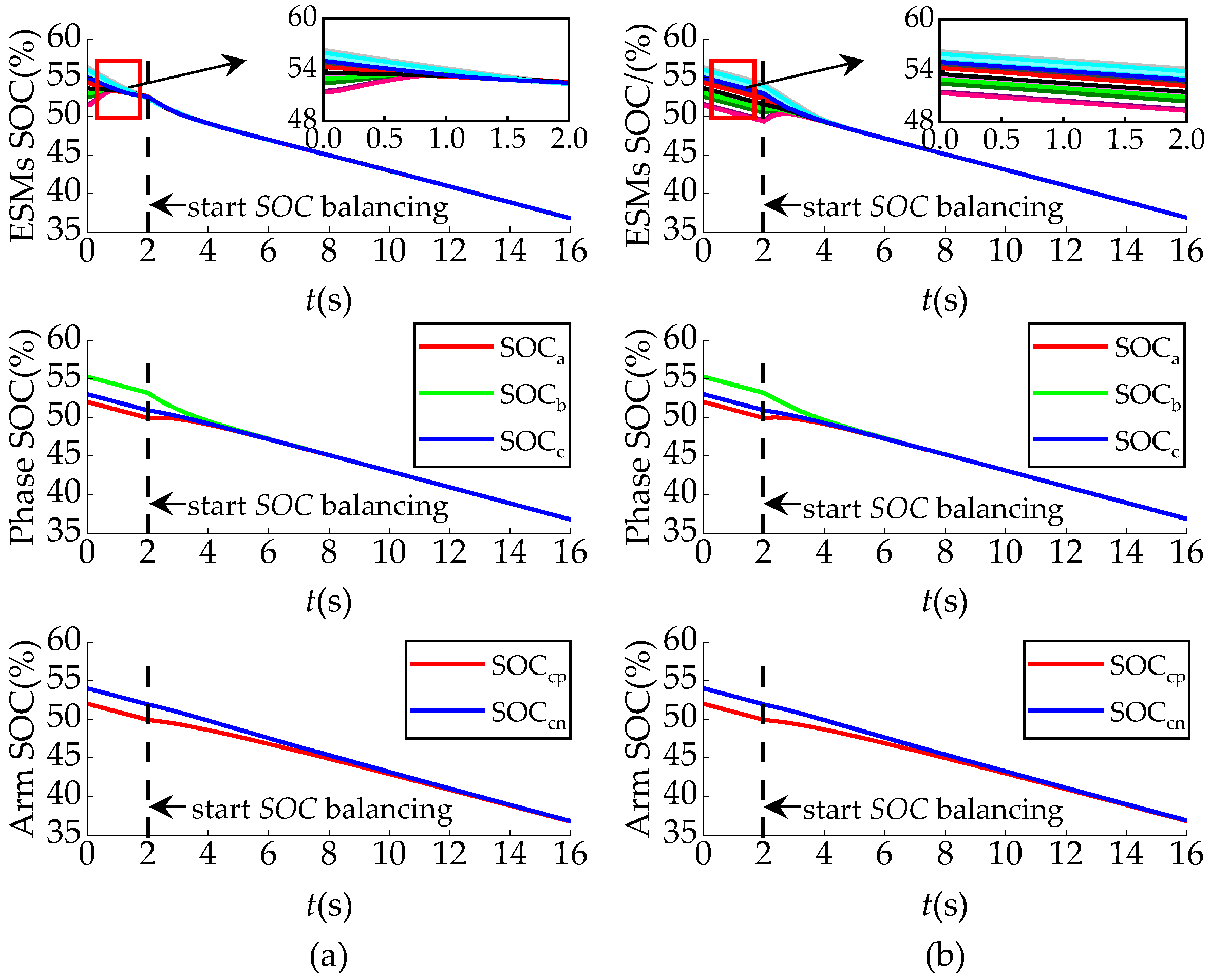
Figure 7 presents a comprehensive performance comparison between the proposed SOC balancing strategy and the traditional method [
24], with both approaches utilizing constant proportional coefficients. Without balancing control, ESM SOC differences remained constant, potentially leading some ESMs to reach threshold limits and exit operation. This would progressively degrade the system’s energy capacity utilization. When balancing control was implemented, both strategies successfully achieved SOC convergence. The maximum SOC difference of the enhanced balancing strategy was reduced from the initial 5.17% to 0.0106%, compared to a reduction of 0.0193% in the traditional strategy. The difference between the two strategies is that the enhanced SOC balancing strategy maintained the balancing of the ESMs regardless of the startup time. Moreover, the proposed strategy required only six centralized energy storage controllers, simplifying system control complexity by a factor of 1/
N. This offers promising potential for large-scale systems containing hundreds of ESMs, where both precision and simplicity are critical.
Subsequently, the impact of the enhanced SOC balancing control strategy on the average switching frequency of the system was verified. The switching frequency of each IGBT was quantified by the number of transitions between the off and on states within one fundamental frequency cycle, multiplied by 50. In this analysis, the average switching frequency of the MMC-SCES was determined using the ESMs in the upper arm of phase A [
43]. Mathematically, this can be expressed as:
where
Non,i is the number of times the
ith IGBT turned on during a fundamental frequency cycle.
The proposed SOC balancing strategy demonstrated a switching frequency of 2474 Hz, closely matching the 2448 Hz frequency of traditional approaches. These high switching frequencies arose from minor voltage variations among ESMs’ capacitors, necessitating continuous real-time adjustments of IGBT triggering pulses in the half-bridge modules.
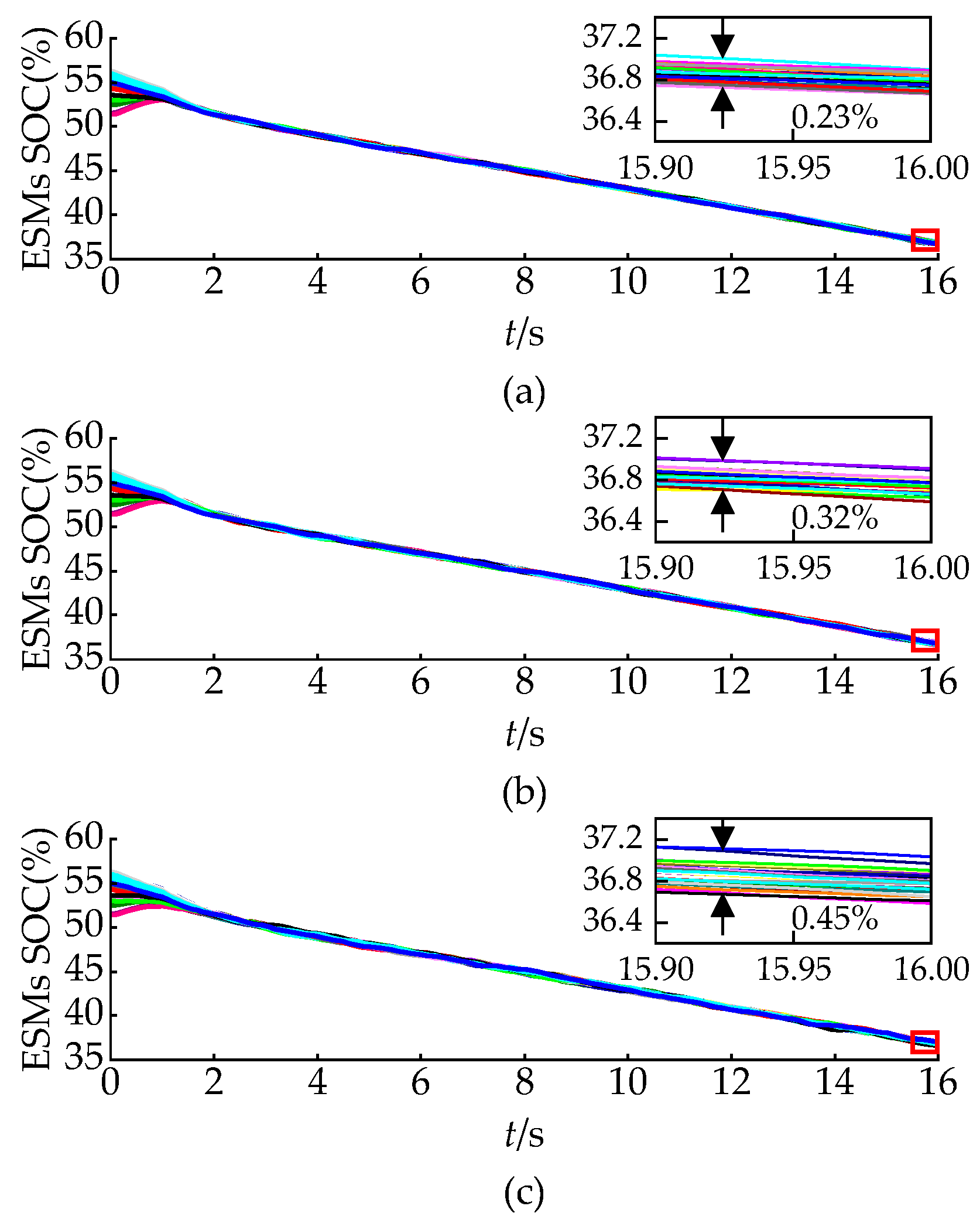
To enhance IGBT efficiency and minimize switching losses, the RSF voltage balancing algorithm can be implemented. It exclusively sorts capacitor voltages for extra ESMs requiring insertion or bypass. As illustrated in
Figure 8, this method effectively maintained SOC balancing while accommodating various voltage unbalance thresholds. The corresponding IGBT switching frequencies in half-bridge modules are listed in
Table 2. The system began with a 5.17% maximum SOC imbalance across ESMs. As the voltage unbalance threshold increased, the maximum SOC difference grew progressively from 0.23% to 0.45%. It also verified the positive correlation between SOC and submodule capacitor voltage. Notably, MMC’s average IGBT switching frequency showed a substantial reduction. Even at σ
m = 6%, the maximum SOC difference remained below 0.50%, satisfying the supercapacitor requirements. Additionally, the average switching frequency reduced to just 135 Hz, which is only 5.46% of the traditional control. Therefore, selecting a suitable capacitor voltage unbalance threshold can achieve effective management between SOC balancing precision and switching loss.
4.2. SOC Balancing Control with Adaptive Proportional Coefficients
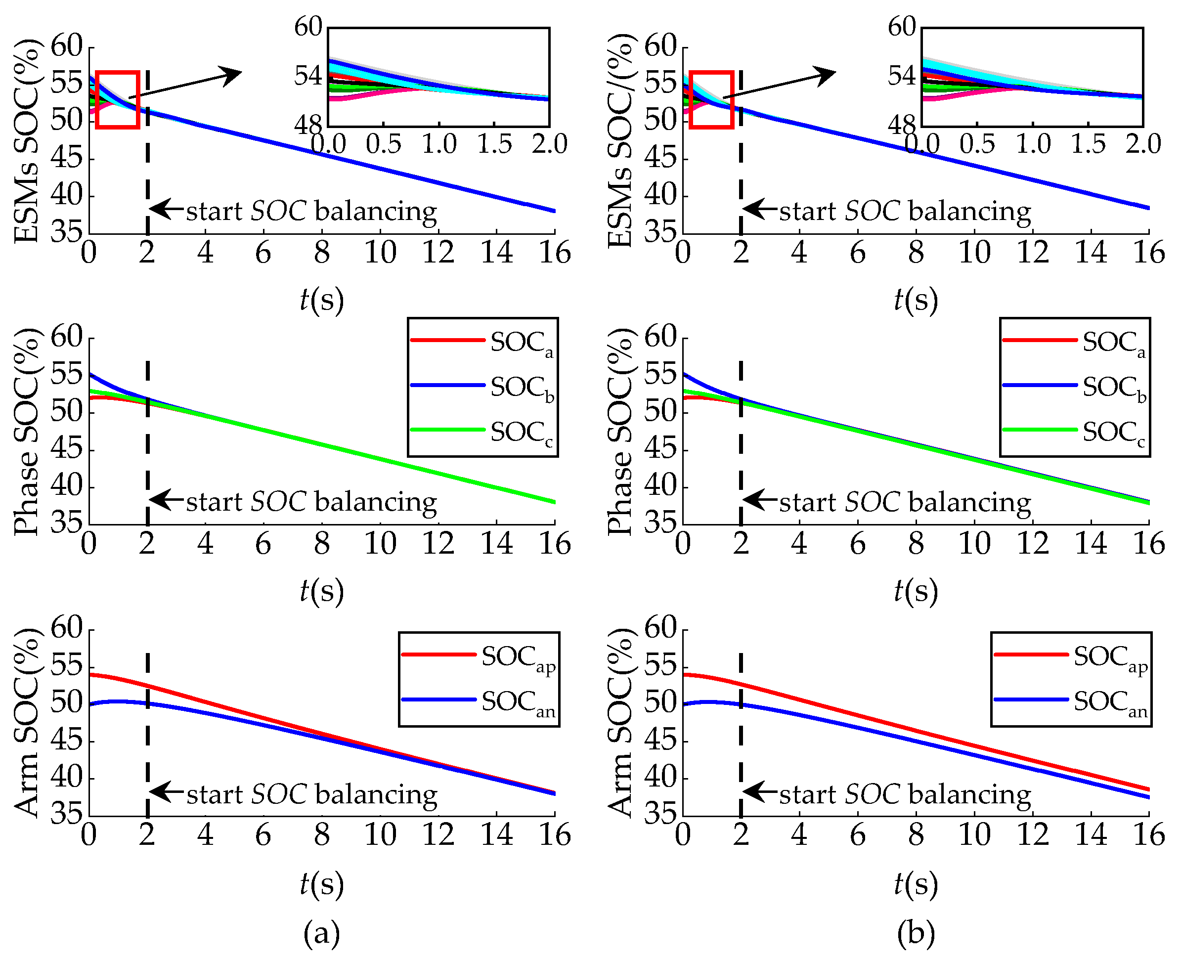
Considering both the SOC balancing speed and the safe operating range of the switches, the scaling factor a was set to 0.5, while b was set to 0.8. The supercapacitor energy storage system operated in a discharge state at 100 MW.
Figure 9 illustrates the relationship between balancing variance and the corresponding adaptive proportional coefficients. The adaptive coefficients increased as SOC differences diminished.
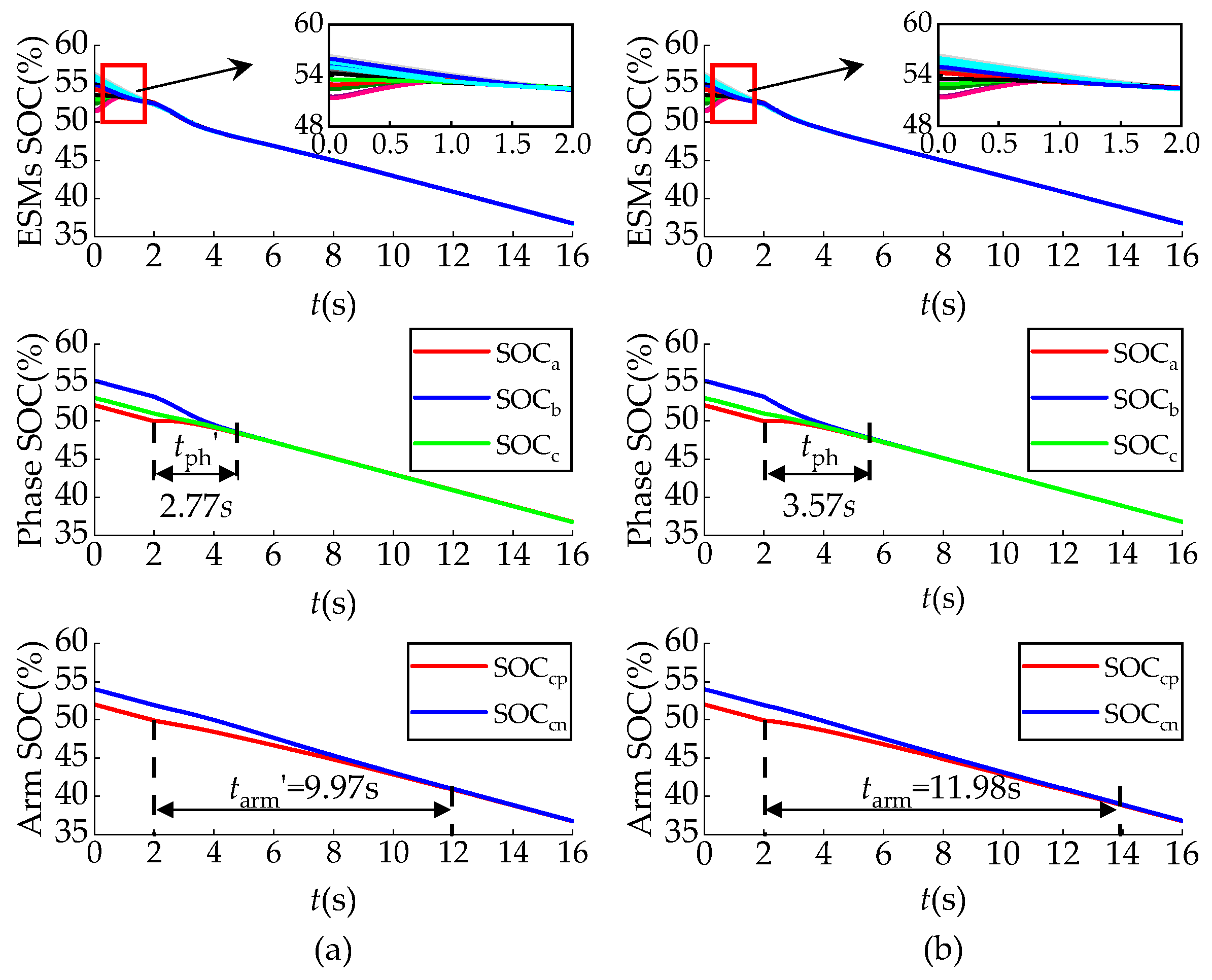
Figure 10 presents SOC simulation results for both constant and adaptive proportional coefficients. With constant proportional coefficients, the balancing speed decreased rapidly as SOC converged. By employing adaptive proportional coefficients, the system maintained a high balancing speed until SOC reached balancing, significantly shortening the balancing time. As shown in
Figure 10, the implementation of adaptive proportional coefficients reduced the SOC balancing time of phases by 0.8 s compared to constant proportional coefficients, while the SOC balancing time of arms decreased by 2 s.
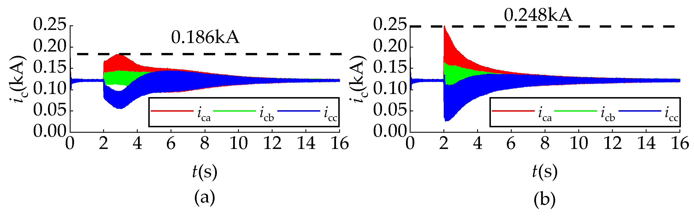
The circulating currents under different control strategies are compared in
Figure 11. The results demonstrate that the proposed adaptive proportional coefficient strategy achieved a 25% reduction in circulating current during the initial balancing time compared to constant coefficient methods. This improvement stemmed from the strategy’s dynamic adjustment mechanism, which optimally resolved the fundamental trade-off between balancing speed and current stress. By automatically regulating the proportional coefficient in response to system conditions, the controller effectively mitigated excessive circulating currents while maintaining rapid SOC convergence.
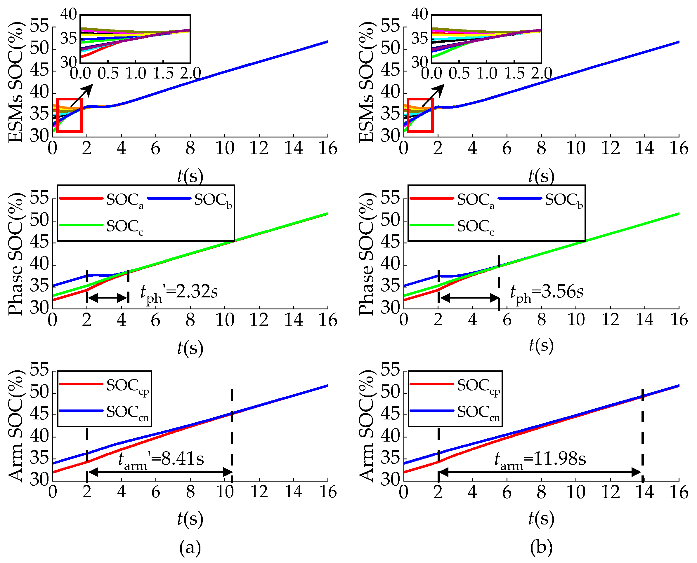
4.3. SOC Balancing Control for Supercapacitor with Different Capacitance
When supercapacitor capacity varies across ESMs, the power of each arm should be adjusted proportionally to its supercapacitor’s remaining capacity. Considering a scenario where the supercapacitor capacity in phase A differs,
Figure 12 presents a comparative analysis of SOC balancing performance under two operating conditions: fixed power allocation and capacity-based power allocation.
Without this adjustment, the SOC of ESMs can still be balanced due to the intrinsic correlation between SOC and submodule capacitor voltage, but an imbalance in SOC persists between arms. This is consistent with theoretical analysis. As observed, after reallocating arm power according to the remaining capacity, the proposed control strategy effectively maintained SOC balance. This confirmed that while the intrinsic voltage–SOC dynamics facilitated SOC balancing among ESMs, capacity-based power allocation was essential to achieve SOC balance across phases and arms.
Table 3 presents a comparative analysis of control architectures between the proposed enhanced SOC balancing strategy and the traditional SOC balancing strategy. The enhanced SOC balancing strategy significantly simplified the control architecture. It also improved balancing performance through adaptive coefficients, achieving a 15% faster balancing speed while reducing initial circulating currents by 25%. Additionally, it maintained balancing capability across varying supercapacitor capacitance.


