4.2. Simulation Settings
- (1)
Simulation Software Settings
In this study, ANSYS Fluent 19.0 was selected for simulating and analyzing the internal flow field of the separator. However, the built-in discrete element functionality of Fluent was inadequate to support the dual-sphere particle model under investigation and to extract the loads on the NGH bonds between dual-sphere particles, failing to meet the research requirements. Therefore, this study simultaneously used the particle discrete element simulation software Altair EDEM 2018 coupled with Fluent to investigate the motion behavior of hydrate particles in the hydrocyclone field.
In Fluent, the Reynolds Stress Model (seven equations), suitable for fluid rotation conditions, was chosen as the turbulence model. To couple with EDEM, the transient calculation method was used. The fluid material was seawater, with a density of 1025 kg/m3 and a viscosity of 0.0017 Pa∙s. The inlet was set as a velocity inlet, with an equivalent velocity of 10.03 m/s corresponding to an inlet flow rate of 4 m3/h. The outlet was set as a pressure outlet.
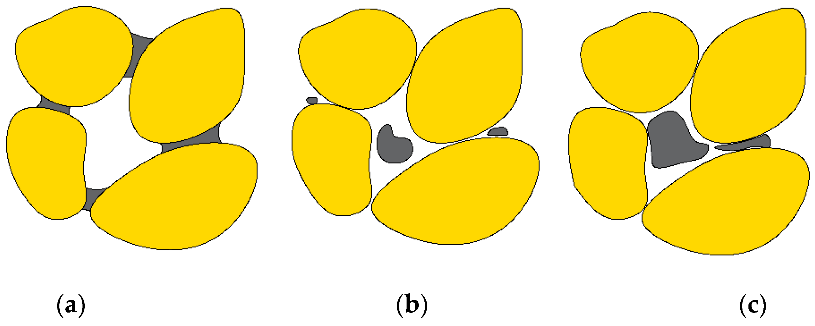
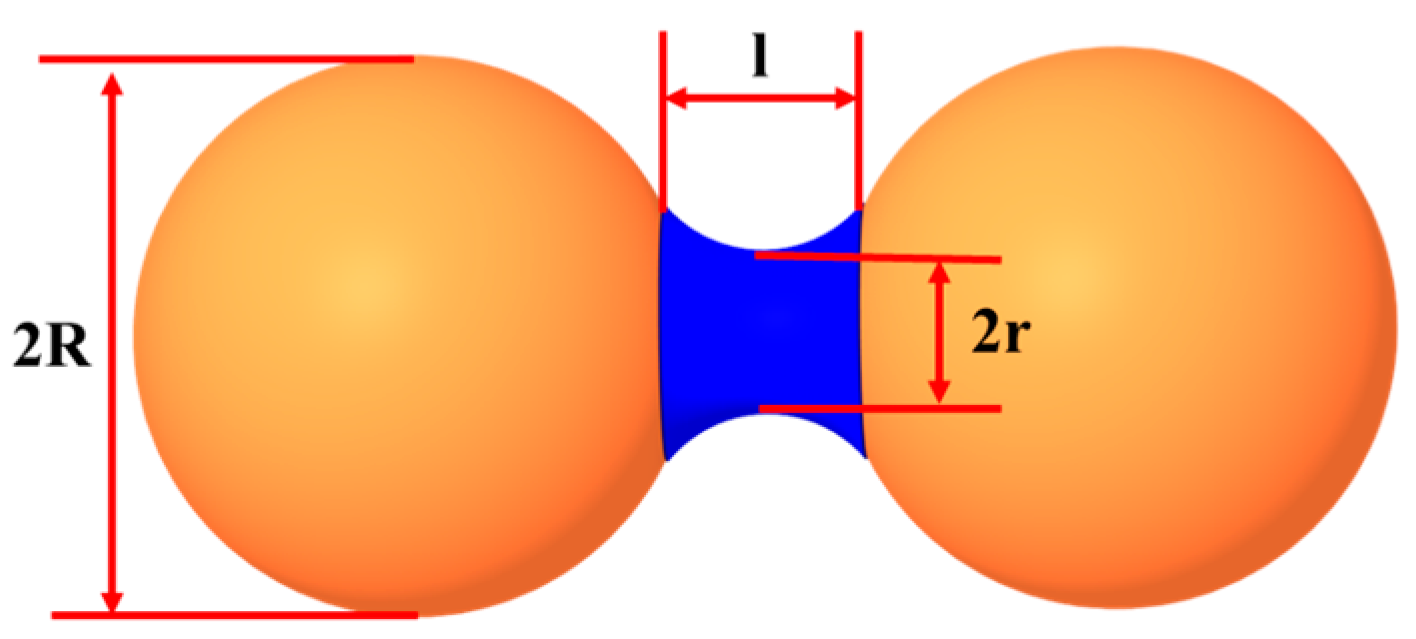
In EDEM, sand particles were modeled as two spheres, each with a diameter of 0.6 mm, and the bonding between particles was established through an API, with a length of 0.06 mm, as shown in
Figure 5. A particle factory was set up at the separator inlet to inject sand particles into the separator at a rate of 1000 particles/s, with a particle velocity of 10.03 m/s. During the post-processing of the simulation results, the loads on the bonds could be extracted to analyze whether GHBS particles could achieve de-bonding. In addition, Hertz–Mindlin (no-slip) was used as the particle-to-particle contact model; the Euler model was the time integration method; the mesh size was 0.9 mm; and the time step was 1.18 × 10
6 s.
- (2)
Coupling Method
In the coupling of ANSYS Fluent 19.0 and EDEM, Fluent was run independently first to allow the flow field within the separator to reach a stable state, followed by coupling with EDEM. Calculations revealed that when the simulation time was no less than 3 s, further increases in the simulation time did not significantly impact the flow field within the separator. Therefore, the pre-simulation time for Fluent was set to 3 s. A two-way coupling method was used, along with a 20-fold Fluent Drag Law Particle Scale-Up Factor. As a result, the actual particle size of the sand particles in the simulation was 30 μm. The reason for using the Fluent Drag Law Particle Scale-Up Factor was that the grid size in EDEM depends on the smallest particle size. Using the real particle size would result in a grid number no less than 1×10¹⁰, and the Particle Scale-Up Factory could greatly reduce the computational costs.
- (3)
Reliability Verification
To verify the reliability of the simulation model, calculations were performed using the same particle size and five inlet flow rates as in experiments reported previously [
10]. The particle linear velocity and particle trajectory distribution obtained were compared with the experimental results. The results showed that the error between the simulation and the experiment did not exceed 10%, indicating that the computational model used in this study was reliable.
- (4)
Simulation Scheme
The helical flow channel enhanced the de-bonding performance primarily by restricting the axial movement speed of GHBS particles, making the pitch of the helical flow channel a major variable. In addition, the particle size significantly impacted the strength of the cementing bonds and their motion behavior. Therefore, the inlet type, the pitch of the helical flow channel, and the particle size were selected as the main research factors to examine the de-bonding performance of the designed composite separator.
Given that the length of the cylindrical section was preliminarily selected as 120 mm, 7, 6, 5, 4, and 3 turns were selected, corresponding to pitches of 17.1, 20, 24, 30, and 40 mm, respectively. The particle size range was 10–50 μm, sizes for which classic hydrocyclone separators cannot efficiently achieve de-bonding. The specific simulation scheme is shown in
Table 4.
4.3. Results and Discussion
- (1)
Pitch
- 1.
Axial Displacement
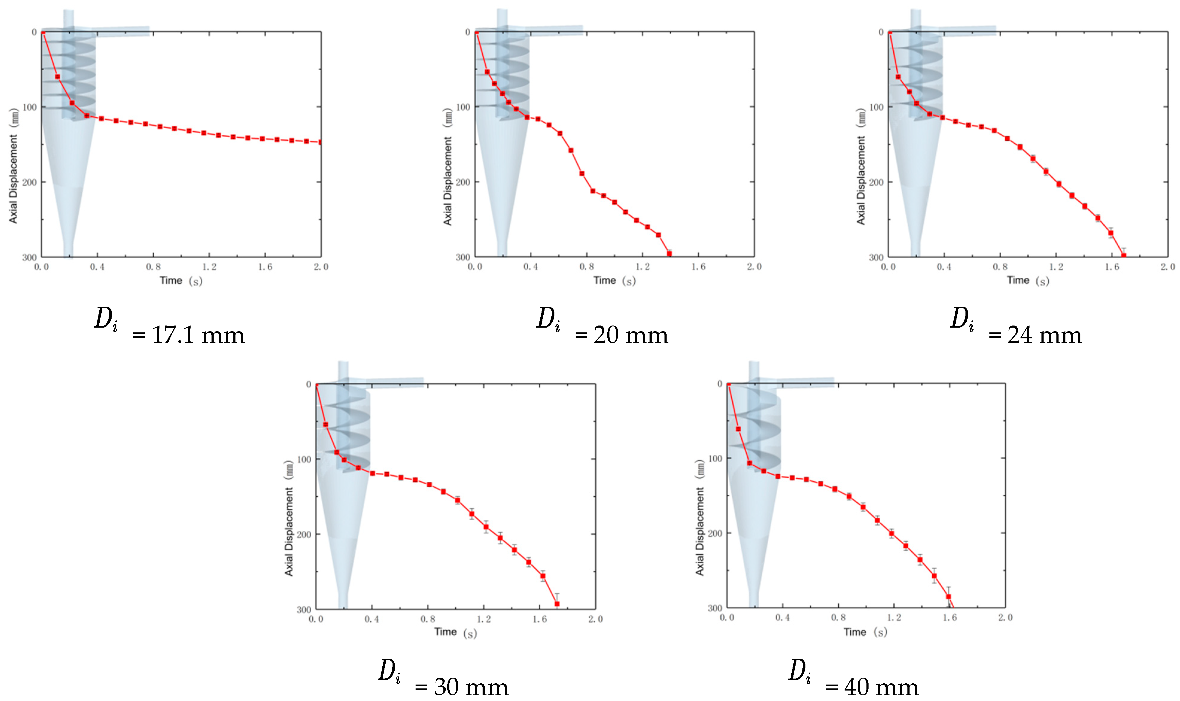
Figure 6 shows the relationship between the axial displacement and time for GHBS particles under different helical flow channel pitches. By comparing these results with those in the literature [
10], it is evident that the addition of the helical flow channel effectively extended the residence time of GHBS particles in the cylindrical section of the separator, from approximately 0.12 s in the classic hydrocyclone separator to about 0.45 s. Although the residence times of particles in the cylindrical section were roughly the same, around 0.45 s, for different pitches, a rapid decrease in the axial velocity was observed near the exit of the helical section. According to the subsequent particle trajectory results (
Figure 7), this turning point occurred because the particles’ high axial velocities overcame the boundary layer effect and caused collisions with the flow channel, indicating that the total residence time of particles in the separator was not linearly related to the pitch.
Moreover, since the helical flow channel reduced the axial velocities of GHBS particles in the cylindrical section, it also affected their axial movement in the conical section. When the pitch was 17.1 mm, the residual axial velocities of the GHBS particles upon leaving the cylindrical section were insufficient to overcome the axial separation in the conical section, preventing movement toward the underflow outlet within 2 s of the simulation.
- 2.
Particle Trajectory
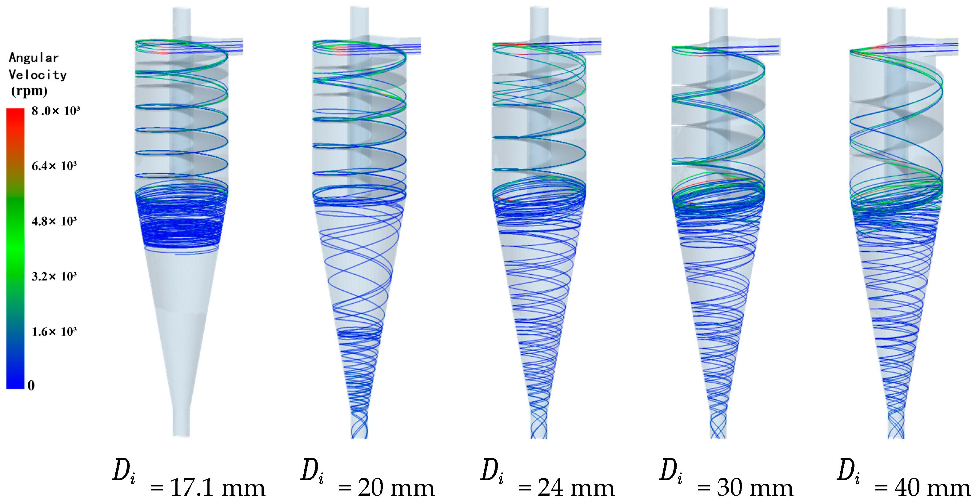
In
Figure 7, it can be observed that under the influence of the helical flow channel, the GHBS particle trajectories transitioned from a dispersed state at the inlet section to moving along the flow channel, eventually aligning with the flow channel. The smaller the helical pitch, the sooner the particle trajectories aligned with the flow channel. For instance, when the pitch was 17.1 mm, the particle trajectory aligned with the flow channel at approximately one-third of the cylindrical section, whereas when the pitch was 40 mm, most particles did not align with the flow channel before leaving the cylindrical section.
- 3.
Cementing Bond Load
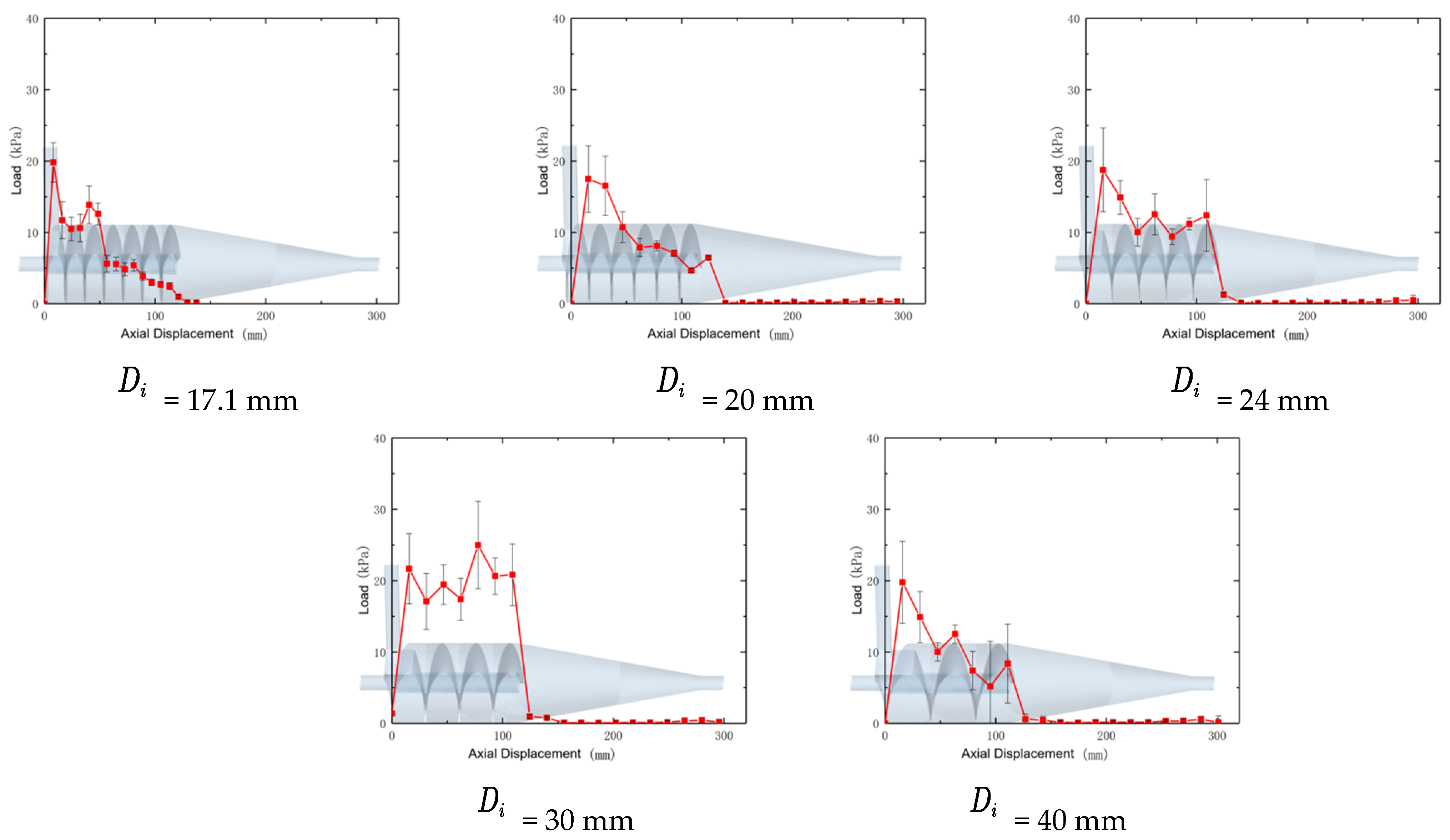
Figure 8 shows the relationship between the load on the cementing bonds of GHBS particles and the axial displacement within the separator under different helical flow channel pitches. As shown in the figure, compared with the classic hydrocyclone separator [
10], the designed composite separator also exhibited a large bond load value at the inlet section for GHBS particles. This peak value was not significantly affected by the flow channel pitch, which remained at around 20 kPa across all five pitches, with a standard error of approximately 4 kPa. However, in the classic hydrocyclone separator, this maximum load appeared only at the inlet and then quickly decreased, whereas in the composite separator, the cementing bond load decreased more slowly with increasing axial displacement and showed a resurgence and a second peak toward the middle and rear sections of the cylinder.
Based on
Figure 6 and
Figure 7, it can be inferred that the second peak occurred due to the particles overcoming the boundary layer and colliding with the helical flow channel. This also explained why the axial position of the second peak shifted further from the inlet as the pitch increased. Among the five simulation results, the separator with a pitch of 40 mm exhibited the highest second peak value of the particle cementing bond stress, exceeding the required 21.5 kPa for de-bonding, indicating that it likely had the best de-bonding performance.
- 4.
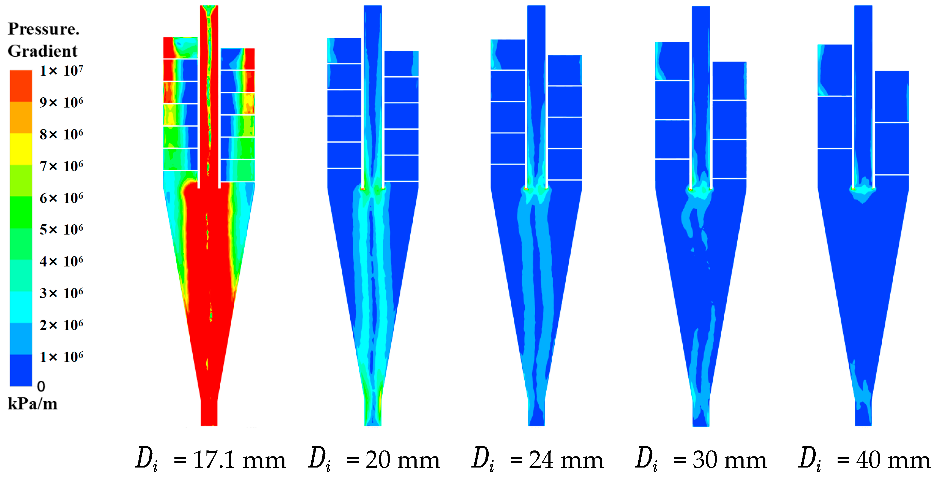
Pressure Gradient
The pressure gradient is an important factor affecting the load on the cementing bonds.
Figure 9 shows the pressure gradient within the flow field of the composite separator for different pitches. As depicted in the figure, the smaller the pitch of the composite separator, the greater the pressure gradient difference on the outer side. According to previous studies [
17,
18,
19], a smaller pitch in the composite separator results in a higher tangential velocity of the fluid within the cylindrical section, causing the dispersed phase to experience greater centrifugal force and, thus, tending to concentrate more toward the wall surface. Consequently, the pressure gradient also increases. Therefore, in the cylindrical section of the composite separator with a smaller pitch, the pressure gradient force on the cementing bonds of the GHBS particles was also greater. Therefore, it can be concluded that when the pitch of the helical flow channel was 30 mm, the composite separator achieved the best de-bonding performance.
- (2)
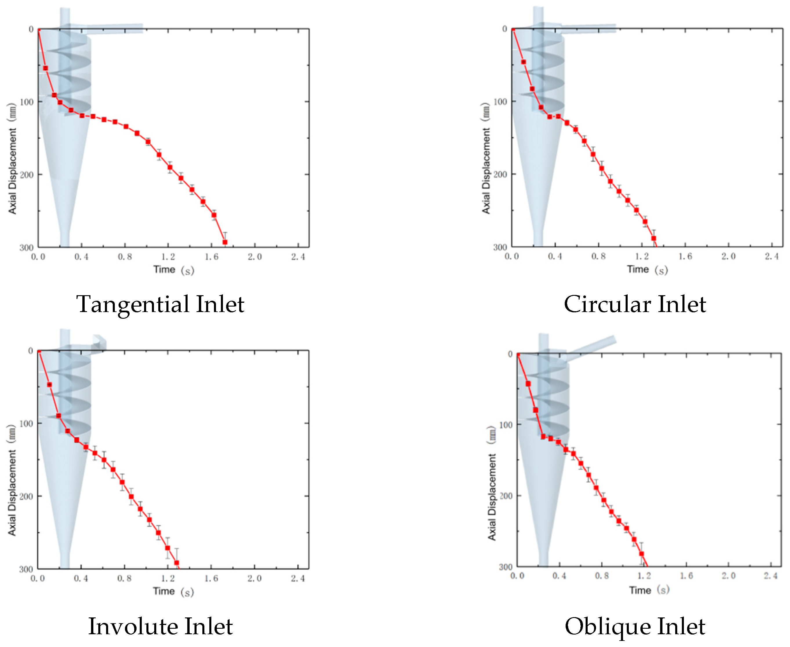
Analysis of the Impact of Inlet Type on De-Bonding Performance of Composite Separator
Recently, there have been numerous studies on the impact of different inlet types on the performances of separators, which have found that inlets such as the involute type can reduce the cut size and improve the separation efficiency. To investigate whether different inlet types would affect or optimize the performance of the composite separator, three types of inlets—circular, involute, and oblique—were selected in addition to the tangential inlet for study.
Figure 10 shows the relationship between the axial displacement and time for GHBS particles in composite separators with different inlet types. As shown in the figure, the residence times of particles in the cylindrical section of composite separators with the four types of inlets, tangential, circular, involute, and oblique, were 0.51, 0.43, 0.33, and 0.33 s, respectively. The total residence times of particles in the composite separators with involute and oblique inlets were also shorter. Shorter residence times favor an improved working performance and throughput of the separator, but are detrimental to the de-bonding performance.
- 2.
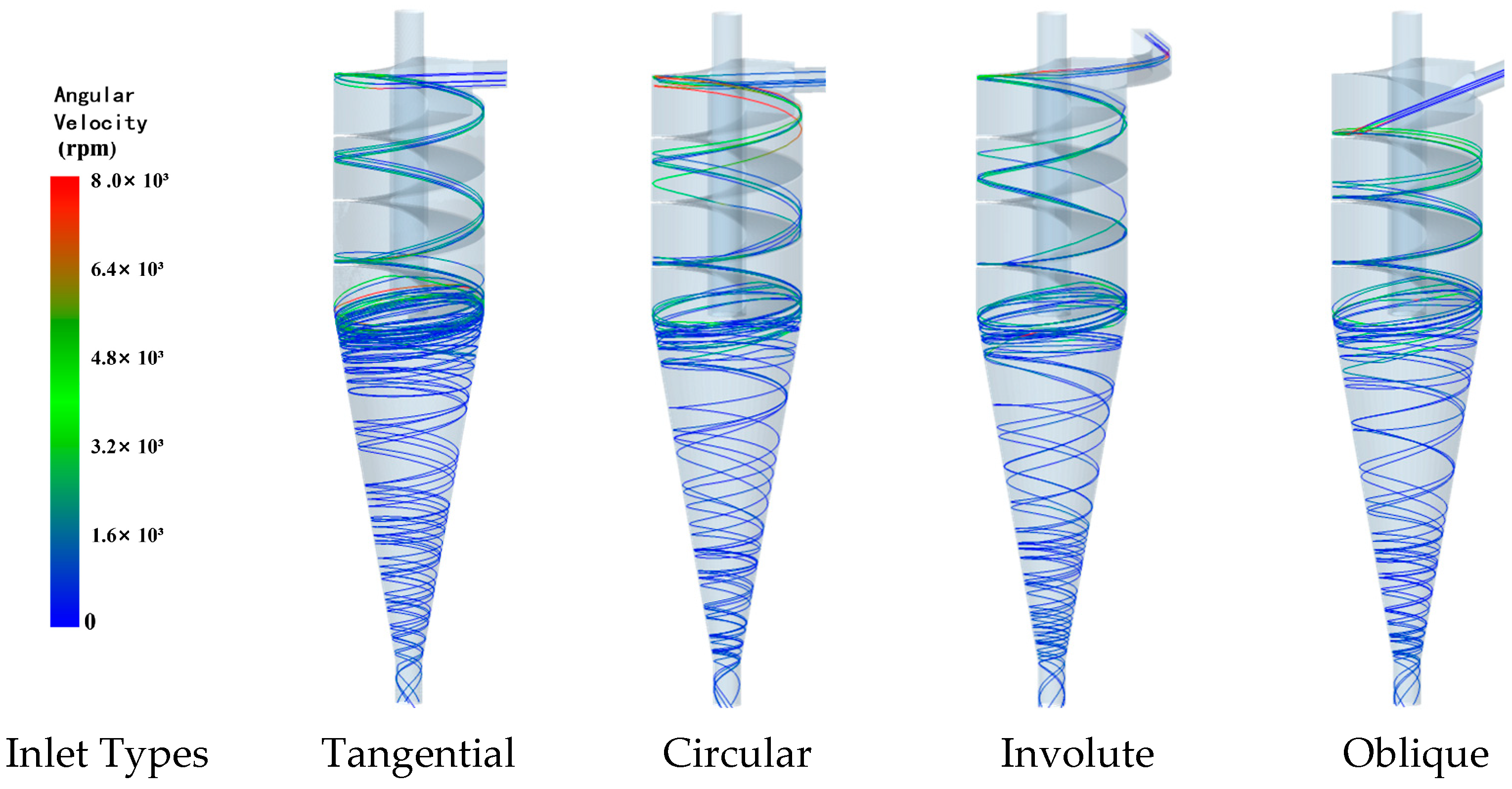
Particle Trajectory
Figure 11 shows the movement trajectories of GHBS particles within the composite separators with different inlet types. As shown in the figure, the main impact of different inlet types on the particle trajectories was reflected in the accelerated convergence of the particle trajectories with the flow channel. GHBS particles passing through the involute and oblique inlets had movement forms and directions that better matched the helical flow channel, leading to quicker completion of the flow in the cylindrical section and shorter residence times. By contrast, in the composite separators with tangential and circular inlets, the particles needed to change their flow direction to adapt to the flow channel at the inlet section, resulting in longer residence times in the cylindrical section.
- 3.
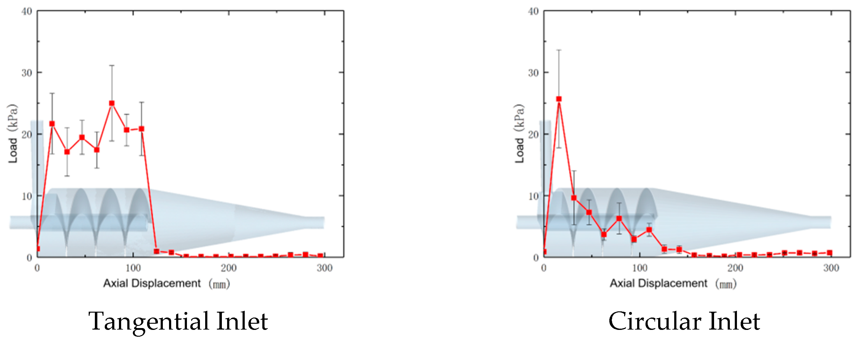
Cementing Bond Load
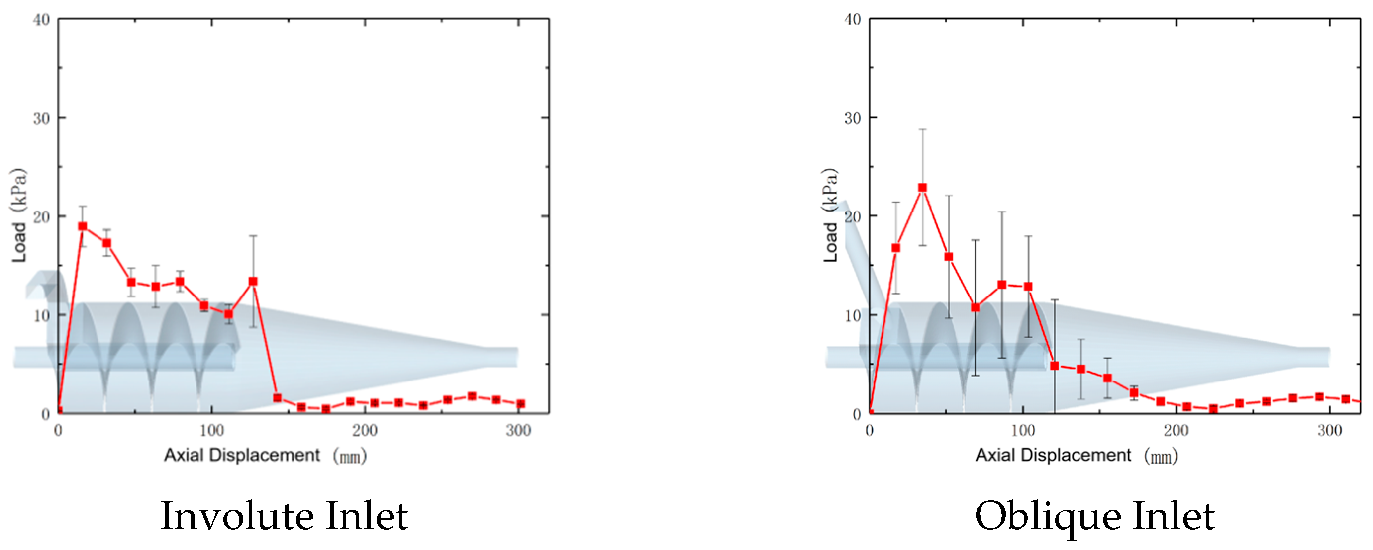
Figure 12 shows the relationship between the load on the cementing bonds of GHBS particles and the axial displacement within the composite separators with different overflow pipe diameters. The findings are as follows.
① The tangential inlet composite separator showed the best performance among the four separators, with the highest average load value reaching about 25 kPa. It also maintained a high-stress level throughout the cylindrical section, indicating a good de-bonding effectiveness.
② The circular inlet composite separator achieved the highest cementing bond stress value of 25.7 kPa. However, high-stress values were only observed in the inlet section, with stress levels in the rest of the cylindrical section being much lower than those in other types of composite separators.
③ In the involute inlet composite separator, the cementing bond stress of the particles reached its maximum value at the inlet and then gradually decreased with increasing axial distance. Since its maximum value only reached about 19 kPa, the involute inlet composite separator could not effectively achieve de-bonding.
④ The stress values in the oblique inlet composite separator differed from those in the other three separators. Instead of reaching the maximum value immediately after entering the separator, the stress peaked at an axial displacement of about 35 mm before gradually decreasing, with a subsequent rise near the exit of the flow channel. This phenomenon occurred because the angle of the inlet was close to that of the flow channel. As a result, the fluid and particles did not immediately attain high angular velocities upon entering the separator, but gradually reached the maximum value after a certain axial displacement.
- 4.
Pressure Gradient
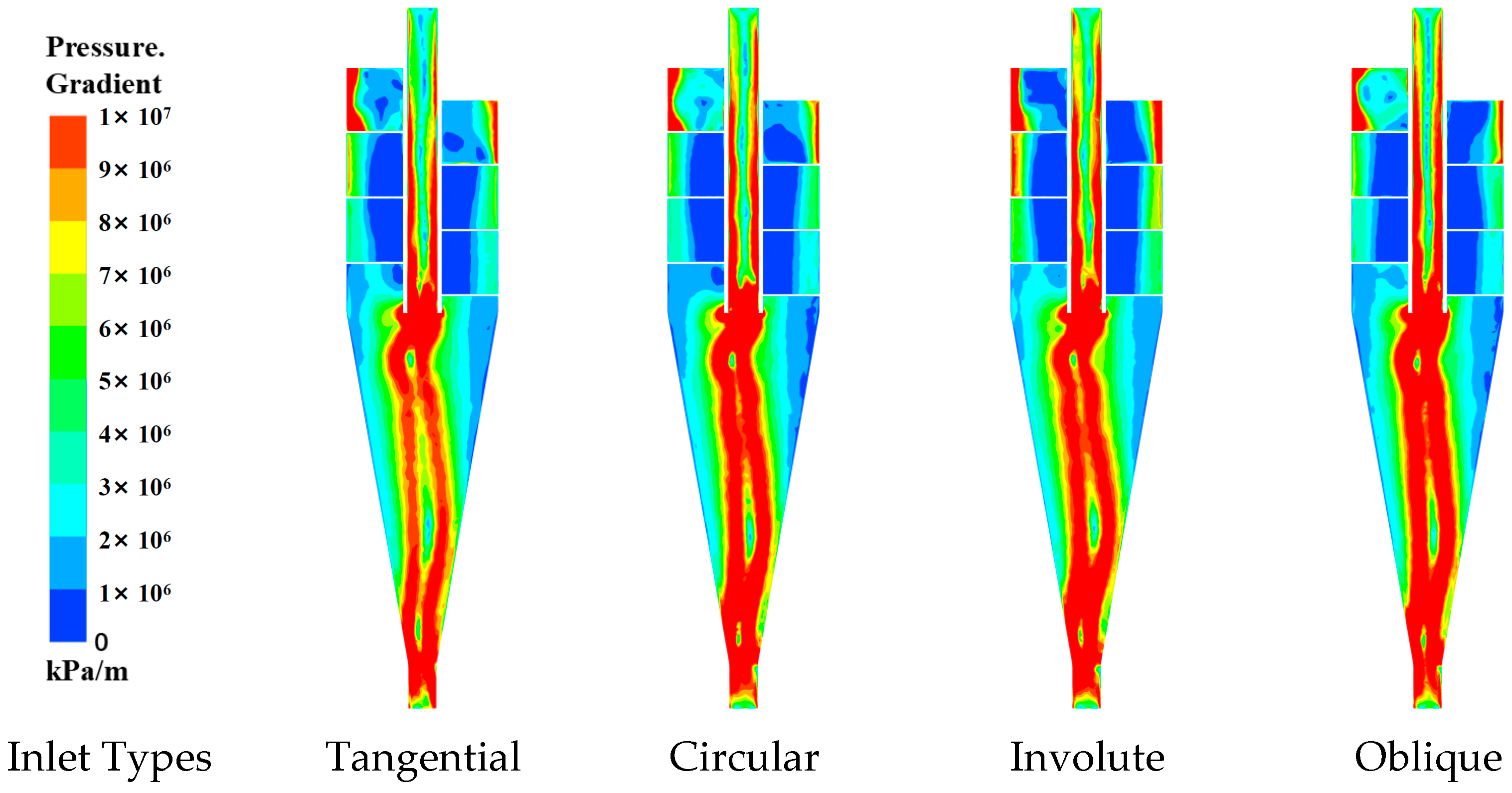
Figure 13 shows the pressure gradient distributions within the composite separators with four different inlet types. As depicted, the influence of the inlet type on the pressure gradient within the separator was primarily noticeable at the inlet section, and the extent of this influence was not significant.
- (3)
Analysis of De-Bonding Performance of Composite Separator for Particles with Different Sizes
- 1.
Axial Displacement
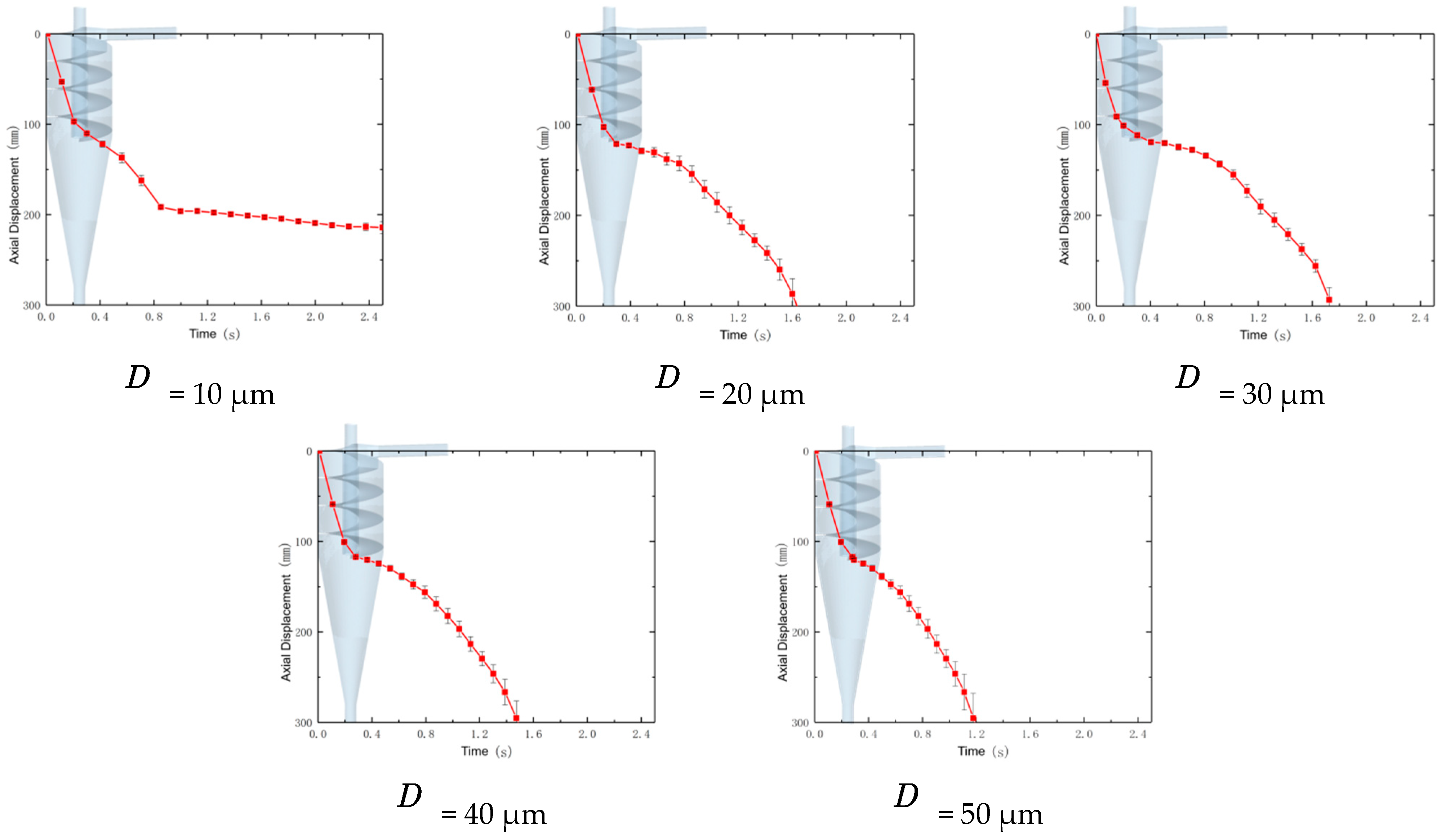
Figure 14 shows the relationship between the axial displacement and time for GHBS particles with different sizes within the composite separator. As shown, except for particles with diameters of 10 μm, particles with various sizes had similar residence times in both the cylindrical section and the overall separator, approximately 0.4 and 1.6 s, respectively. This phenomenon significantly differed from the movement patterns of GHBS particles in a classic hydrocyclone separator. The reason for this discrepancy was that in a classic separator, larger particles, driven by their greater mass, have higher axial speeds and accelerations within the cylindrical section and encounter greater axial resistance in the conical section. In the designed composite separator, the helical flow channel caused particles with different sizes to have similar axial speeds, and the speed losses when entering the conical section were also similar, resulting in comparable residence times within the separator.
In addition, it can be observed that 10 μm particles, after moving to the middle position of the separator conical section, ceased to exhibit further axial movement and remained in the conical section. This phenomenon did not occur in the classic separator. The reason was that small-sized GHBS particles, lacking sufficient axial speed in the cylindrical section, could not overcome the resistance of the conical surface to reach the underflow outlet upon entering the conical section, leading to accumulation in the middle of the conical section. It is foreseeable that when a large number of particles accumulated in the conical section of the separator, some particles would be pushed toward the underflow outlet by the particles behind them, while others would be pushed radially, eventually crossing the zero-velocity envelope and being discharged from the overflow outlet. Therefore, it can be concluded that the composite separator reduced the separation efficiency of GHBS particles with diameters less than 10 μm, thereby reducing the separator’s operational performance.
- 2.
Particle Trajectory
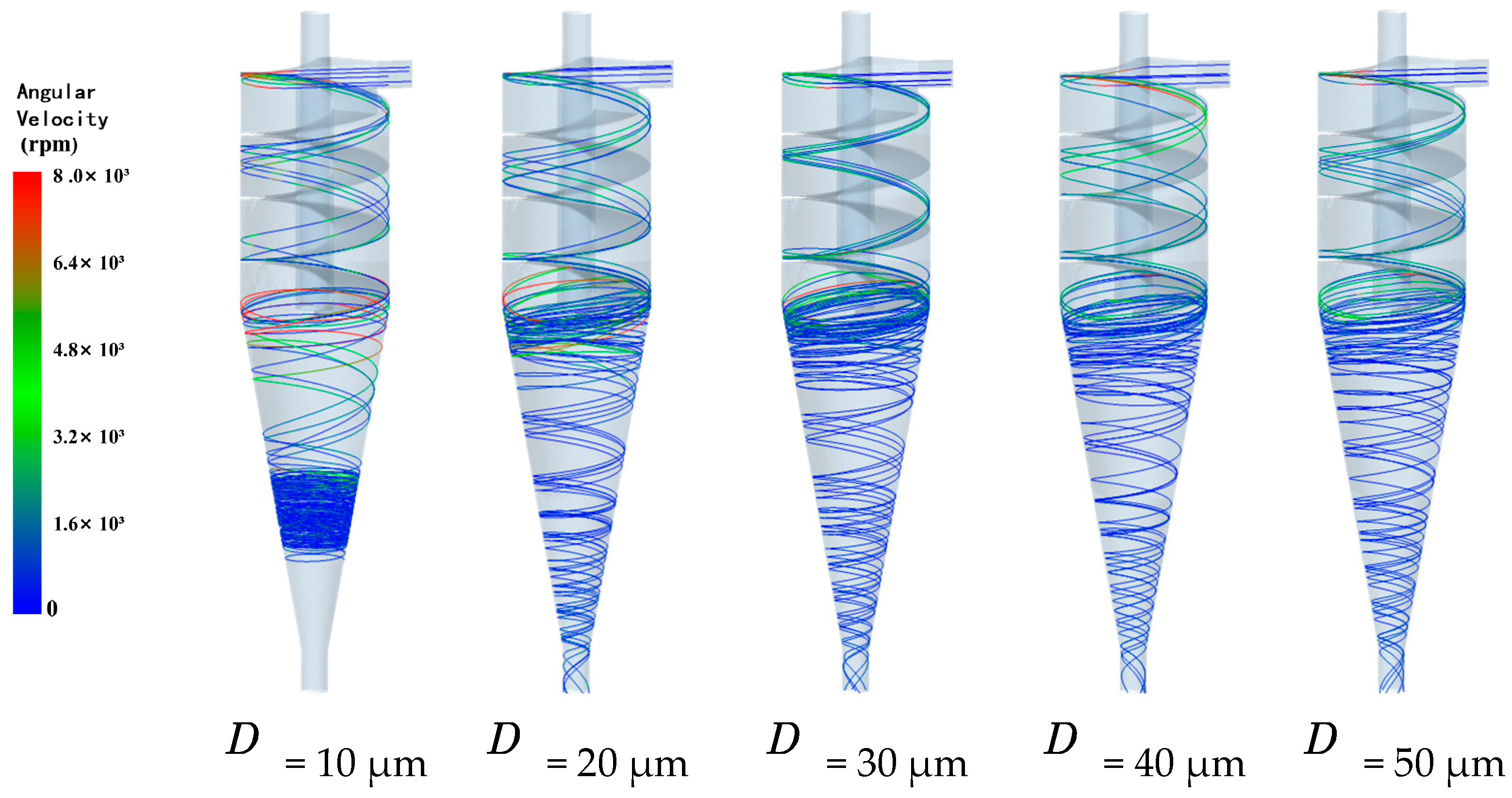
Figure 15 shows the trajectories of GHBS particles with different sizes within the composite separator. Particles with diameters of 10 μm did not leave the separator through the underflow outlet within 3 s, but instead accumulated in the middle of the conical section. The results indicate that when the particle diameter was not less than 20 μm, there was no significant difference in the particle trajectories, only differences in the angular velocity values. Particles with diameters of 10 μm had a minimal residence time at the junction between the cylindrical and conical sections. They initially possessed high axial velocities upon entering the conical section, but experienced a rapid decrease in the axial velocity shortly thereafter, ultimately remaining in the middle of the conical section. In addition, some particles were observed to rise axially.
- 3.
Cementing Bond Load
Figure 16 shows the relationship between the load on the cementing bonds and the axial displacement for GHBS particles with different sizes within the composite separator. The figure indicates that the cementing bond load values were proportional to the particle size. When the particle diameter was 10 μm, the cementing bond load level could not reach the 21.5 kPa required for de-bonding. When the particle diameter reached 20 μm, although the average bond load still did not reach 21.5 kPa, there was a possibility of achieving de-bonding based on the standard error. When the particle diameter was not less than 30 μm, the cementing bond load could consistently exceed the 21.5 kPa required for de-bonding. Therefore, this separator structure can effectively de-bond GHBS particles with diameters of no less than 30 μm and can partially de-bond GHBS particles with diameters of 20 μm, but cannot efficiently de-bond smaller particles.
- 4.
Pressure Gradient
Figure 17 shows the internal pressure gradient of the composite separator when separating particles with different sizes. It shows that when the particle diameter was not more than 30 μm, the pressure gradient within the separator increased with increasing particle size, reaching a maximum value at a particle diameter of 30 μm, but it rapidly decreased when the particle diameter exceeded 30 μm. This phenomenon occurred because at smaller particle sizes, heavier particles were more likely to gather near the wall, increasing the pressure gradient. However, when the particle size exceeded a certain range, the total mass of the dispersed phase became too large, leading to the accumulation of many large particles at the underflow outlet, affecting the flow field distribution within the separator and resulting in a decrease in the pressure gradient. Therefore, it can be concluded that the operational performance of the separator was limited when handling large quantities of large particles.


