1. Introduction
Omnidirectional mobile robots (OMRs) have gained significant attention in recent years due to their ability to move in any direction without the need for reorientation; this characteristic provides them with a remarkable advantage in maneuverability compared to other mobile platforms [
1]. As a result, they have been increasingly adopted in various fields such as manufacturing, warehouse logistics, autonomous transport in hospitals, and service or personal assistance environments, as their versatility enables precise movements in constrained spaces, optimizing operation time and improving efficiency in automated tasks [
2]. However, despite the wide implementation of omnidirectional robots, most research and commercial platforms are limited to low- or medium-payload applications, especially when using three-wheel configurations. Moreover, there is a lack of experimental studies that validate the dynamic and kinematic models of high-load 3A systems in controlled environments, particularly under open-loop control strategies. This research addresses these challenges by proposing and validating a robust three-wheel omnidirectional platform capable of handling up to 300 kgf, offering a valuable reference for future developments in heavy-duty mobile robotics.
OMRs are commonly classified based on the number of omnidirectional wheels used, with three- and four-wheel configurations being the most prevalent. Although robots with three wheels, arranged at 120-degree intervals (known as the 3A configuration), are appreciated for their mechanical simplicity, lower cost, and ease of control—making them suitable for controlled environments or research purposes—they offer limited stability and payload capacity [
3]. In contrast, four-wheel configurations provide enhanced weight distribution, better dynamic stability, and greater load-handling capabilities, making them preferable for more demanding industrial applications. This comes at the cost of increased mechanical and control complexity [
4]. The decision between these configurations should balance structural simplicity, motion accuracy, payload requirements, and operational environment characteristics.
In commercial applications related to material handling, a strong preference for four-wheel omnidirectional configurations has been observed, especially those using mecanum wheels; these systems allow for lateral, diagonal, and rotational motion with high precision. Platforms with this configuration tend to achieve the highest structural efficiency ratios, defined as the payload fraction. A high ratio indicates that these platforms can carry significantly more load compared to their own weight, which is crucial in industrial settings where space is limited and structural efficiency is a key factor [
5].
Regarding the types of omnidirectional wheels used, the most common are omniwheels and mecanum wheels [
6]. Omniwheels feature rollers arranged perpendicularly to the main axis, allowing smooth movements on flat surfaces and requiring simpler control [
7]. Mecanum wheels, on the other hand, have rollers positioned at diagonal angles, providing better traction and performance over slightly uneven surfaces [
8]. However, they require more complex control algorithms to achieve precise motion and tend to generate more vibration during operation [
9].
In this context, and from a mechatronic perspective, this article presents the development of an omnidirectional mobile robot prototype with three symmetrically arranged wheels at 120 degrees (3A configuration). The process begins with the kinematic and dynamic modeling of the system, including inverse kinematics and the derivation of dynamic equations based on the Jacobian matrix of the chosen configuration. The mechanical design stage involved the development of a custom omnidirectional wheel, followed by the design of the robot’s platform structure. Both components are validated through finite element analysis (FEA) to assess stress distribution and determine appropriate safety factors. Subsequently, trajectory instructions are defined, enabling the operator to specify linear movements, curves, and rotations by setting global destination coordinates and estimating motion parameters such as speed and acceleration. Open-loop control algorithms are implemented to execute these planned motions, and the electronic components, including motors, drivers, and microcontroller boards, are carefully selected to meet the system’s dynamic and kinematic requirements.
The robot is designed to transport up to 300 kgf in a controlled environment, focusing on validating the mathematical model rather than obstacle avoidance or autonomous navigation. To evaluate the prototype’s performance, experimental tests are conducted under different load conditions using two operating modes: automatic and teleoperated. In the automatic mode, the operator predefines specific trajectories, while in the teleoperated mode, the robot is controlled in real-time using a manual joystick. For both modes, the execution time and deviation from the desired endpoint are measured to assess operational limitations, including the maximum load each mode could handle. Based on these results, a performance index (payload fraction) is calculated to quantitatively evaluate the system’s efficiency under various operating scenarios.
The article is organized into eight sections.
Section 2 reviews the fundamentals and compares different omnidirectional robot configurations.
Section 3 details the design and selection of the three-wheel platform.
Section 4 develops the kinematic and dynamic models.
Section 5 describes the integration of mechanical, electronic, and control systems.
Section 6 presents experimental validations. Finally,
Section 7 discusses potential improvements and concludes with the main achievements and industrial implications of this work.
2. Related Work
The development of omnidirectional robots has advanced considerably in recent decades, driven by the growing need for mobile platforms that can operate precisely and agilely in complex, spatially constrained environments. These advances have been made possible by the refinement of key components, such as mechanum and omnidirectional wheels, as well as the integration of more sophisticated control systems that enable holonomic motions. In this section, a comprehensive comparative analysis of the most commonly used omnidirectional robot configurations is presented, evaluating their advantages and limitations in terms of maneuverability, balancing and energy efficiency. In addition, the selection of the design used in this project is justified, arguing how the decisions made respond to optimization criteria to ensure superior performance in the execution of specific tasks, such as transporting heavy loads or moving in confined spaces.
2.1. Omnidirectional Four and Three-Wheeled Robots
Omnidirectional mobile robots (OMRs) can be primarily classified into four-wheeled and three-wheeled configurations. Four-wheel designs, typically using mecanum or omnidirectional wheels, offer an even distribution of forces and greater static and dynamic balancing, especially when handling heavy loads. However, they require precise synchronization among all wheels, which increases the complexity of control and demands higher energy consumption [
4].
On the other hand, three-wheeled omnidirectional robots distribute the reaction forces through only three points, offering improved traction efficiency. This design is mechanically simpler, with all wheels maintaining ground contact even on uneven surfaces. The three-wheel configuration also stands out for its reduced number of components, leading to lower manufacturing and maintenance costs [
10].
Although three-wheeled robots may present challenges related to dynamic stability, proper structural design and advanced control strategies can effectively compensate for this limitation. Furthermore, in tasks involving omnidirectional motion on flat, smooth surfaces, three-wheeled platforms can achieve comparable performance to four-wheeled robots [
3].
Recent comparative studies, such as the one by Tagliavini et al. [
11], evaluated three- and four-wheeled omnidirectional mobile robots from a kinematic perspective, analyzing their behavior under different motion commands. Their findings suggest that three-wheeled robots can achieve highly accurate omnidirectional movement while benefiting from simpler mechanical construction, particularly advantageous in environments with constrained spaces.
In addition to academic studies, several commercial omnidirectional platforms have been developed for industrial applications.
Table 1 summarizes the key characteristics of some representative designs.
This comparison highlights that while four-wheeled platforms often dominate in high-payload industrial environments, three-wheeled designs are mechanically simpler and can achieve competitive performance, especially when the payload-to-weight ratio (payload fraction) and maneuverability are critical factors.
The design proposed in this article adopts a three-wheel configuration, prioritizing mechanical simplicity, reduced energy consumption, and ease of manufacturing, without compromising precision or load-carrying capabilities—essential features for applications in industrial logistics and material transportation.
2.2. Omnidirectional Wheel Designs
The design and arrangement of the omnidirectional wheels are critical to ensure the unique mobility of these robots [
6]. Among the most common designs are the following:
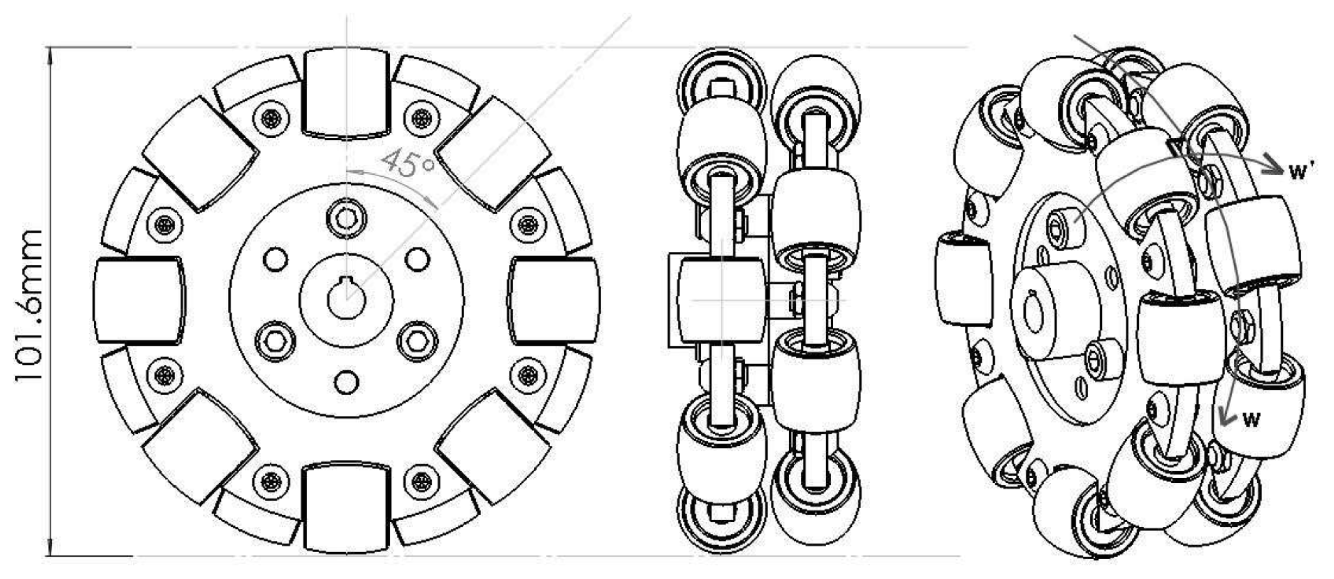
Mechanum wheels: These widely used wheels feature rollers arranged at a fixed angle (usually 45°) with respect to the main wheel axis as depicted in
Figure 1. They offer good maneuverability and allow smooth movements, although their design can generate unwanted slippage and requires greater complexity in their manufacturing [
18].
Figure 1.
Mecanum wheel, with rollers arranged at 45° [
19].
Figure 1.
Mecanum wheel, with rollers arranged at 45° [
19].
Universal/Omniwheels: Universal or omnidirectional wheels are fundamental elements to enable holonomic motion in mobile robots. This type of wheel consists in passive rollers distributed around the perimeter of a main wheel, with their axes perpendicular to the wheel’s axis of rotation, which facilitates movement in any direction in the plane, as shown in
Figure 2. Despite their versatility and low cost compared to other options such as mecanum wheels, omniwheels present limitations, such as vibrations [
20] induced by discontinuity points between the rollers and the ground, as well as lower load capacity. One strategy to mitigate these vibrations is the use of dual configurations, where two wheels are assembled with offset rollers, increasing the points of contact with the floor and improving the balancing of the robot.
3. Global Platform Design
The design basically consists of a vehicle with a body in the shape of an equilateral triangle as depicted in
Figure 3. An omnidirectional wheel set is placed on each side. A motor in conjunction with a reducer will provide the necessary torque to each wheel.
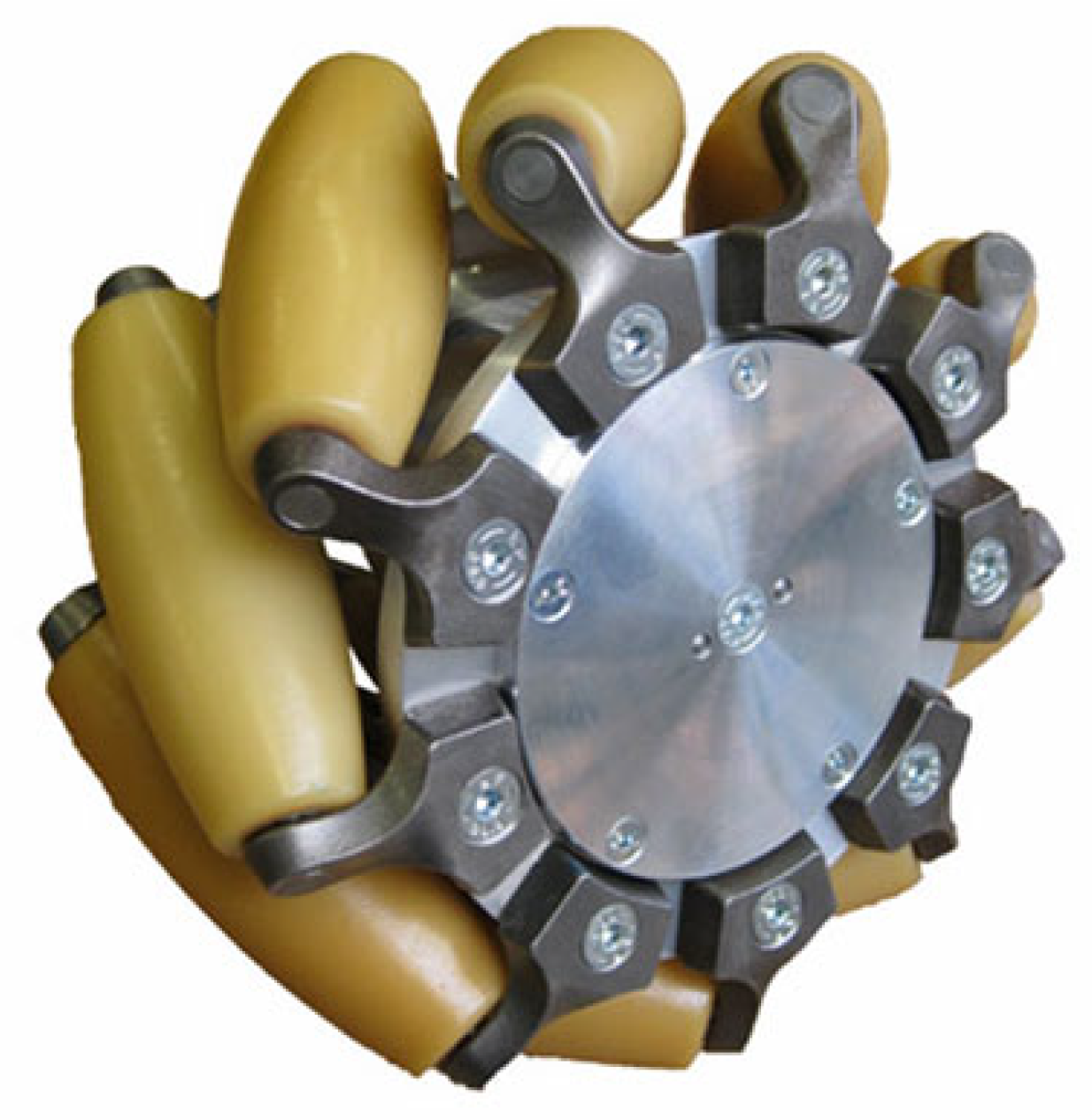
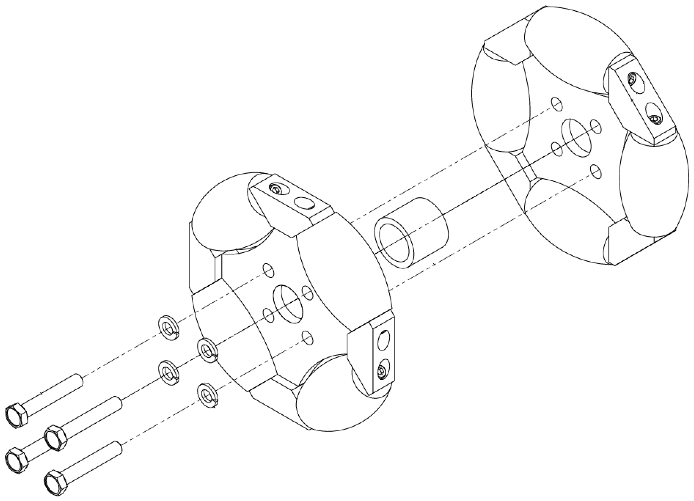
The design of each omnidirectional wheel set proposed in this paper is inspired by configurations reported in the state of the art (see
Section 2.2) and enhances their performance by assembling two omniwheels in tandem. Each wheel features rollers spaced at 90° intervals, and the two wheels are mounted with a 45° angular offset as illustrated in
Figure 4. This offset ensures staggered roller contact with the ground, distributing the load more evenly and smoothing the motion.
The double-row design primarily aims to mitigate vibrations caused by the intermittent contact of the rollers during movement. By overlapping the ground contact points, the transition between rollers becomes smoother, which reduces abrupt variations in contact forces. This significantly diminishes vertical oscillations transmitted to the robot’s structure and improves the overall stability of the platform.
Furthermore, the increased continuity of contact improves traction and reduces lateral slip, especially during combined translational and rotational motions. This characteristic is crucial for industrial applications that demand high precision and stable load transportation.
Supporting this approach, Hijikata et al. proposed in 2023 [
7] that, compared to Mecanum wheels, omnidirectional wheels generally exhibit lower vibration levels due to a more stable ground contact behavior.
Additionally, Simerean and Tătar [
22] analyzed various omnidirectional wheel designs, including double-row configurations, concluding that such designs improve stability and reduce vibratory phenomena in mobile robots.
The effectiveness of the proposed dual-wheel design with 45° offset has been experimentally validated in our platform, demonstrating enhanced stability, improved traction, and reduced vibrations during operations on cemented surfaces with controlled friction, ultimately ensuring safer and more efficient handling of heavy loads in industrial environments.
The three motors are controlled by microcontrollers and power drivers. Power supply is provided by hard-wired sources connected to a 110/220 VAC electrical outlet. As this is a cargo vehicle, all elements, such as wheels, axles, structure, and constituent parts, are designed under these considerations.
The control of the platform is based on an algorithm (see
Section 6.1), where it will be assigned trajectories to follow, analogous to pose-to-pose (PTP) and continuous path (CP) control [
23].
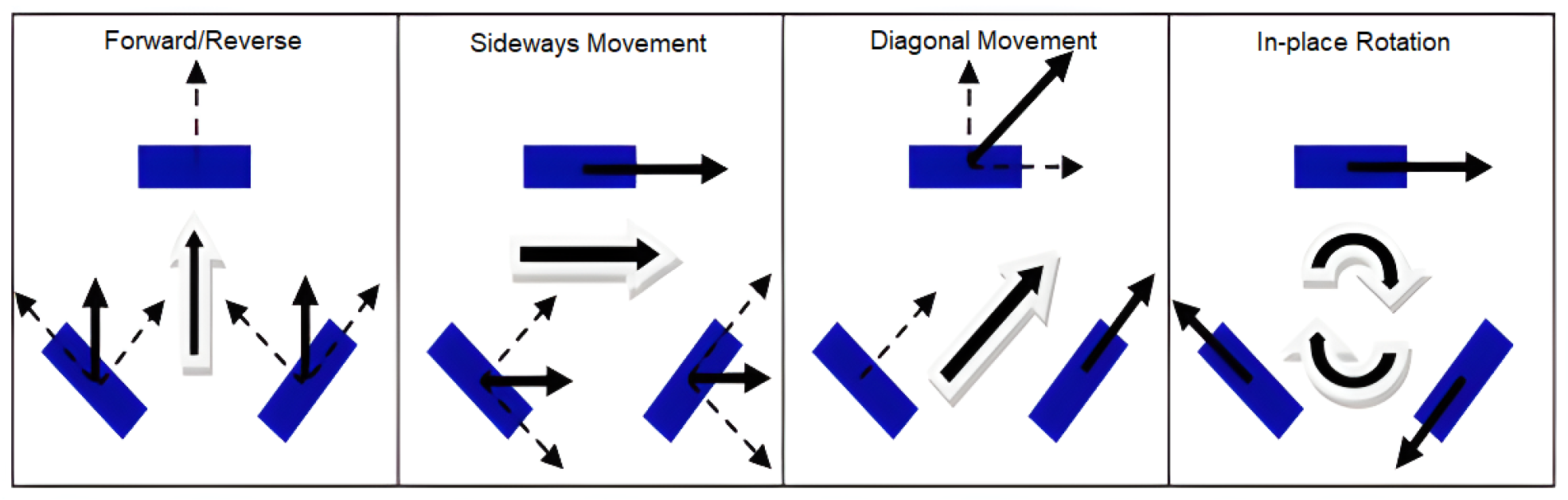
The omnidirectional robot platform has three wheels positioned at 120°, where each of the wheels has the ability to rotate in both directions as seen in
Figure 5.
This bidirectional rotation is achieved through the use of stepper motors directly coupled to each wheel via a pulley-and-belt transmission system. The motors are controlled independently, allowing the precise command of angular velocity and direction for each wheel.
The combination of bidirectional wheel rotation with the symmetric 120° wheel arrangement enables the robot to perform simultaneous translational and rotational movements in any direction, maintaining a smooth and continuous trajectory even in confined industrial environments. This configuration results in greater maneuverability for avoiding obstacles or performing lateral positioning, the seamless execution of trajectories in crowded spaces without the need for global reorientation, and improved time efficiency and accuracy when docking at fixed stations or following production lines.
This approach has been theoretically and numerically validated by Rubies et al., proposed in 2024 [
3], who analyzed eleven configurations of three-wheeled omnidirectional mobile platforms. They demonstrated that the 3A configuration—featuring wheels spaced 120° apart with an orientation of
—exhibited bidirectionality errors close to zero (below
).
4. Mathematical Modeling
This section gathers the most relevant aspects related to modeling mobile robots with wheels, for which we have chosen a configuration of a holonomous mobile robot (comprising the same number of degrees of freedom as Cartesian space coordinates) of three degrees of freedom for position and orientation on the plane. Two analyses are performed: the kinematic analysis obtaining the matrix of both displacements and angular velocities of the wheels; and in the dynamic analysis, the torque as the main factor. Guided by the equations developed by V. F. Muñoz Martínez et al. [
24], new kinematic mathematical expressions are obtained based on our reference system.
4.1. Kinematic Modeling
The kinematic model forms the basis of the mathematical development necessary to design the controller and simulate the behavior of the vehicle, being a fundamental pillar in the planning and control of movements. This model establishes the relationship between the movements of the wheels and the desired trajectory, making it possible to predict and adjust the robot’s displacement accurately. For its construction, certain constraints are considered that simplify the equations and provide a framework for analysis:
The robot moves on a flat surface.
There are no flexible elements in the robot structure (including wheels).
The wheels have one or no steering axis so that the latter is always perpendicular to the ground.
No frictions are considered in the moving elements of the vehicle or against the ground.
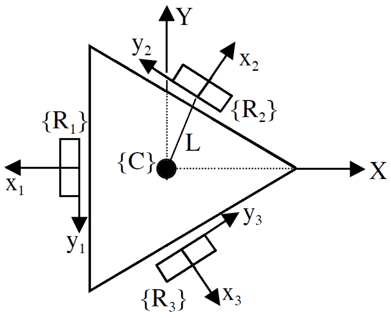
The geometrical configuration of the omnidirectional robot platform, which is the object of the kinematic and dynamic study, is shown in
Figure 6.
As shown in
Figure 6, the kinematic configuration of the robot is based on an equilateral triangular structure, where an omnidirectional wheel is located at each of its sides. The origin of the system
, located at the geometric center of the platform, is at a distance “L” [
25] from each of the wheels. In addition, the wheels are distributed at specific angles
with respect to the axis “X” as detailed in
Table 2. This angular arrangement allows the precise and uniform control of the omnidirectional motions, enabling both kinematic modeling and system dynamics.
In addition, each element is described by the following parameters:
: Displacement of the platform on the abscissa axis of the system .
: Displacement of the platform on the ordinate axis of the system .
: Displacement of the wheel on its abscissa axis of its respective system .
: Displacement of the wheel on its ordinate axis of its respective system .
r: Radius of the rollers.
R: Radius of the wheels.
: Angular displacement of each roller, for translation.
: Angular displacement of each wheel, for translation.
: Angular displacement of each wheel, for rotation.
: Angular displacement of each wheel, total.
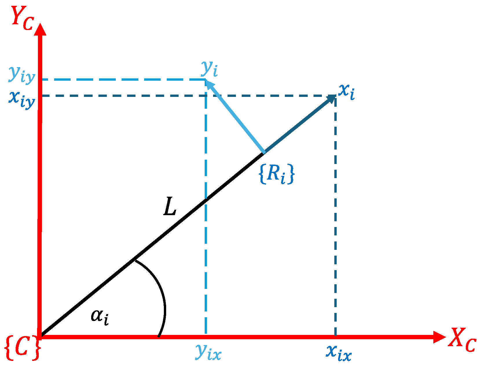
The coordinate system of the body and the
n wheels are shown in the following
Figure 7.
The following generalized equations of
y
show only the translational motion (
1) taken from
Figure 7:
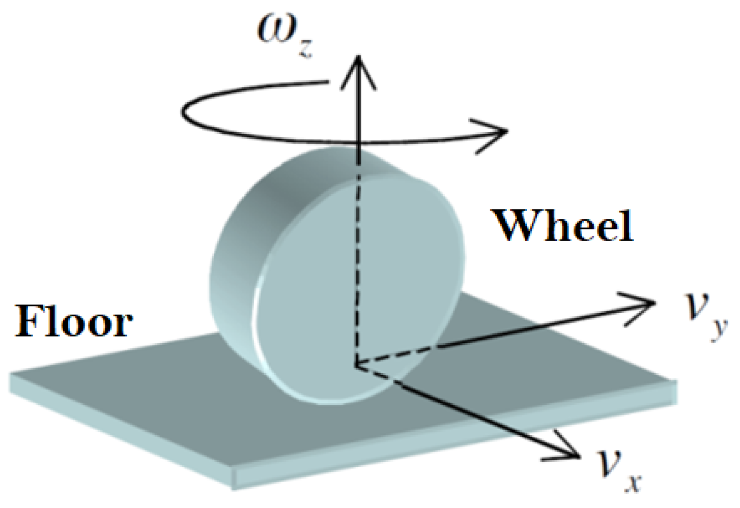
The kinematic behavior is established on the principle that the wheels in contact with the ground behave as a planar joint with three degrees of freedom as shown in
Figure 8.
The following
Figure 9 shows the system of the omnidirectional wheel.
From the reference system of the omnidirectional wheel (
Figure 9), we obtain the mathematical expressions (
2)
The negative direction is for rotating clockwise. Equating the Equations (
1) in (
2), and isolating the expression (
), we obtain the following.
First, it concentrates on the displacement of the platform on the abscissa axis of the system
:
Now the displacement of the platform on the ordinate axis of the system
is
Equations (
3a) and (
3b) are equated to obtain
Replacing the values of
in
Table 2, the wheel translation expression (
5) is expressed as follows:
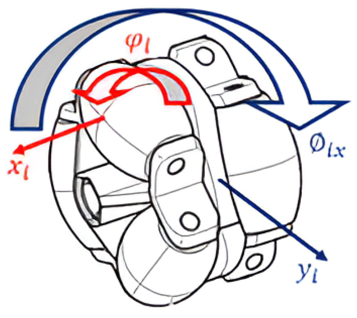
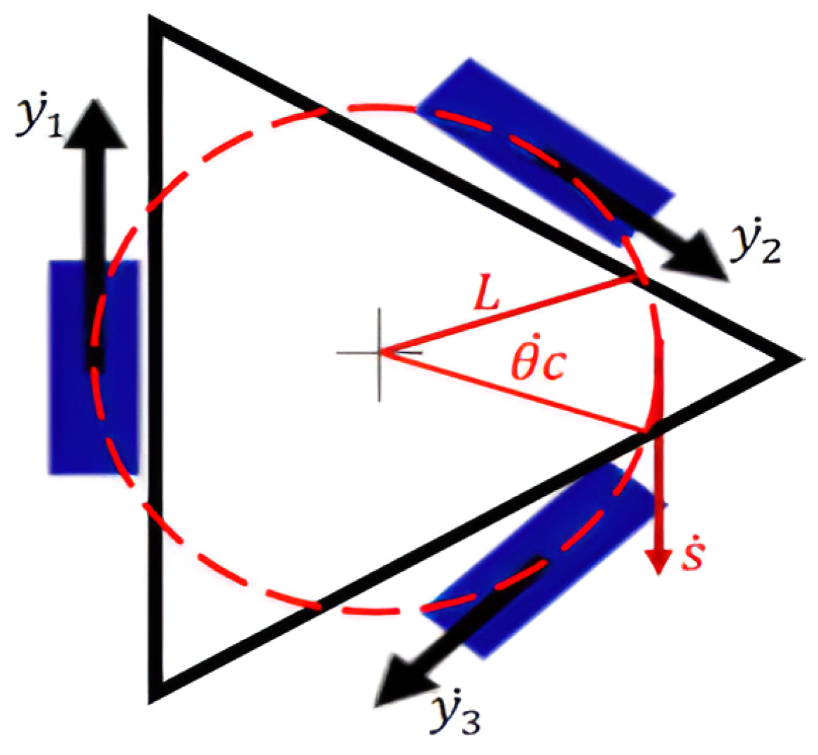
With respect to its rotation, all variables are known to be equal as illustrated in
Figure 10, where
is the tangential velocity,
L is the turning radius, and
is the angular velocity of the robot.
We know that the formula for the perimeter traveled for the rotational motion of the prototype is expressed by the Equation (
6)
We obtain the expressions of rotation (
7) in each wheel
By the superposition theorem, translation and rotation are combined (
8):
Finally, the angular equations of each wheel (
9) are expressed in the matrix below:
The matrix is derived to express the wheel variables in velocities (
10)
where
J is known as the Jacobian matrix, which is used to calculate the actuation required on the wheels for the robot to reach a certain velocity state. The velocities of the body (
11) are expressed as a function of those of the wheel, by means of the inverse Jacobian
(obtained by the inversion of the
J matrix):
4.2. Dynamic Modeling
The dynamics considers the evolution of the position, velocity, and acceleration of the robot platform in response to the actuating torques of the wheels. The same constraints imposed in the previous section dedicated to the kinematic modeling are considered. The Lagrangian equation is taken as a paradigm to determine the torque of each wheel (
12):
where
is the Lagrange equation involving only the kinetic energy, particularized for the case of zero potential energy (the robot moves on a flat and horizontal surface). Using (
13), we obtain the kinetic energy of the robot, which is divided into two terms:
where each of the terms is defined below. The first of these, the translational kinetic energy (
14)
, is
The parameter M constitutes the mass of the loaded platform. The rotational component (
15)
is given in the following expression:
where
and
are defined as the inertias of the platform and the wheel referred to their respective axes of rotation. Replacing and performing the differential calculation, we obtain the torques of each wheel (
16):
where
is the angular acceleration of the respective wheel.
5. Mechatronic Design
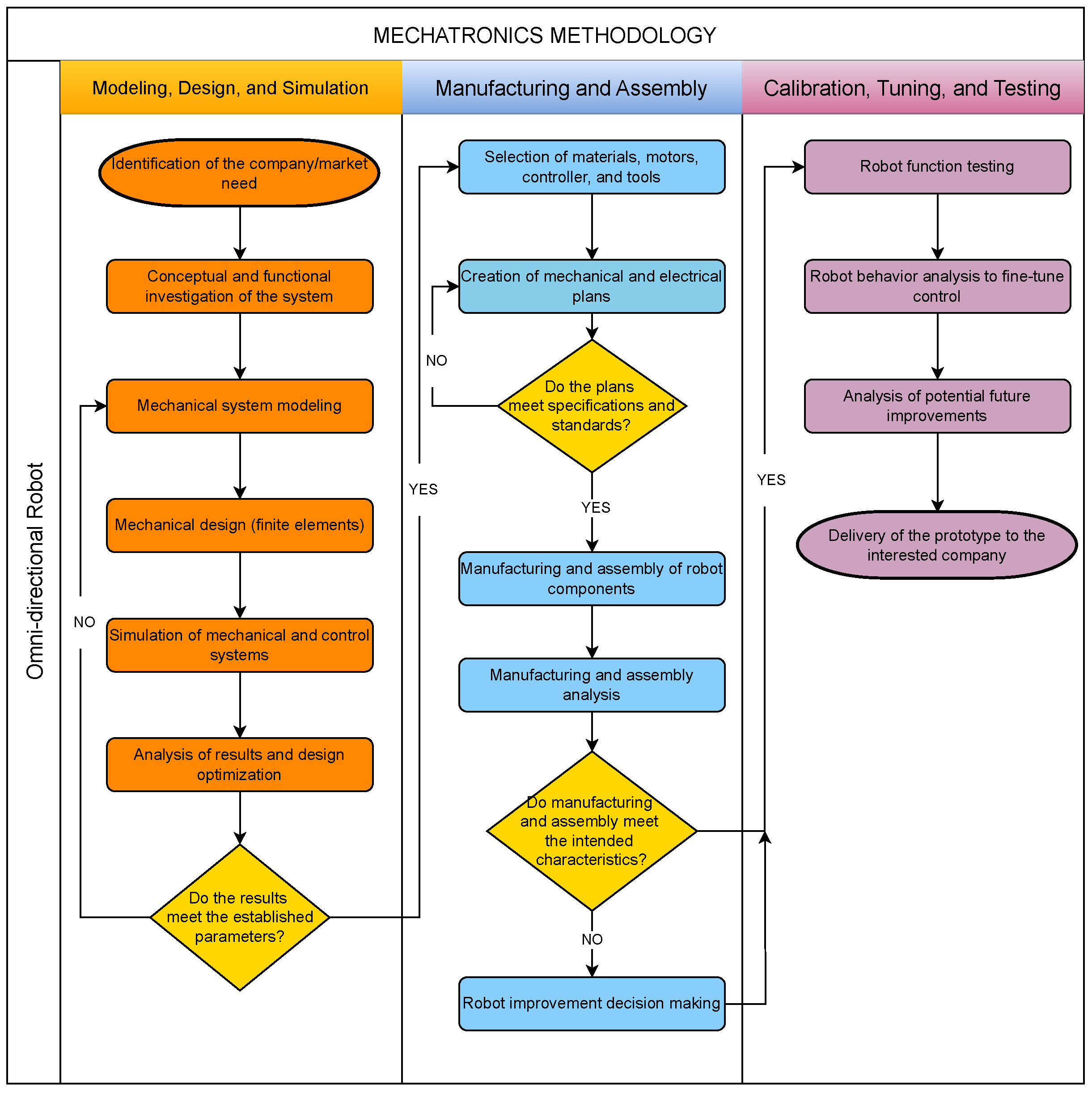
Mechatronics engineering is an interdisciplinary branch of engineering that focuses on the integration of mechanical systems with electronics and software, as depicted in
Figure 11, to create functional products. For the design of the omnidirectional platform, we start with the mechanical part to determine the physical parameters, such as geometry and weight; with the values of these parameters, together with the kinematic and dynamic equations, the algorithm for obtaining torque and the automatic control of the omnidirectional movement is determined. Finally, the electronic components are selected.
For ease of explanation and better understanding, the following subsections detail the designs separately.
5.1. Mechanical System
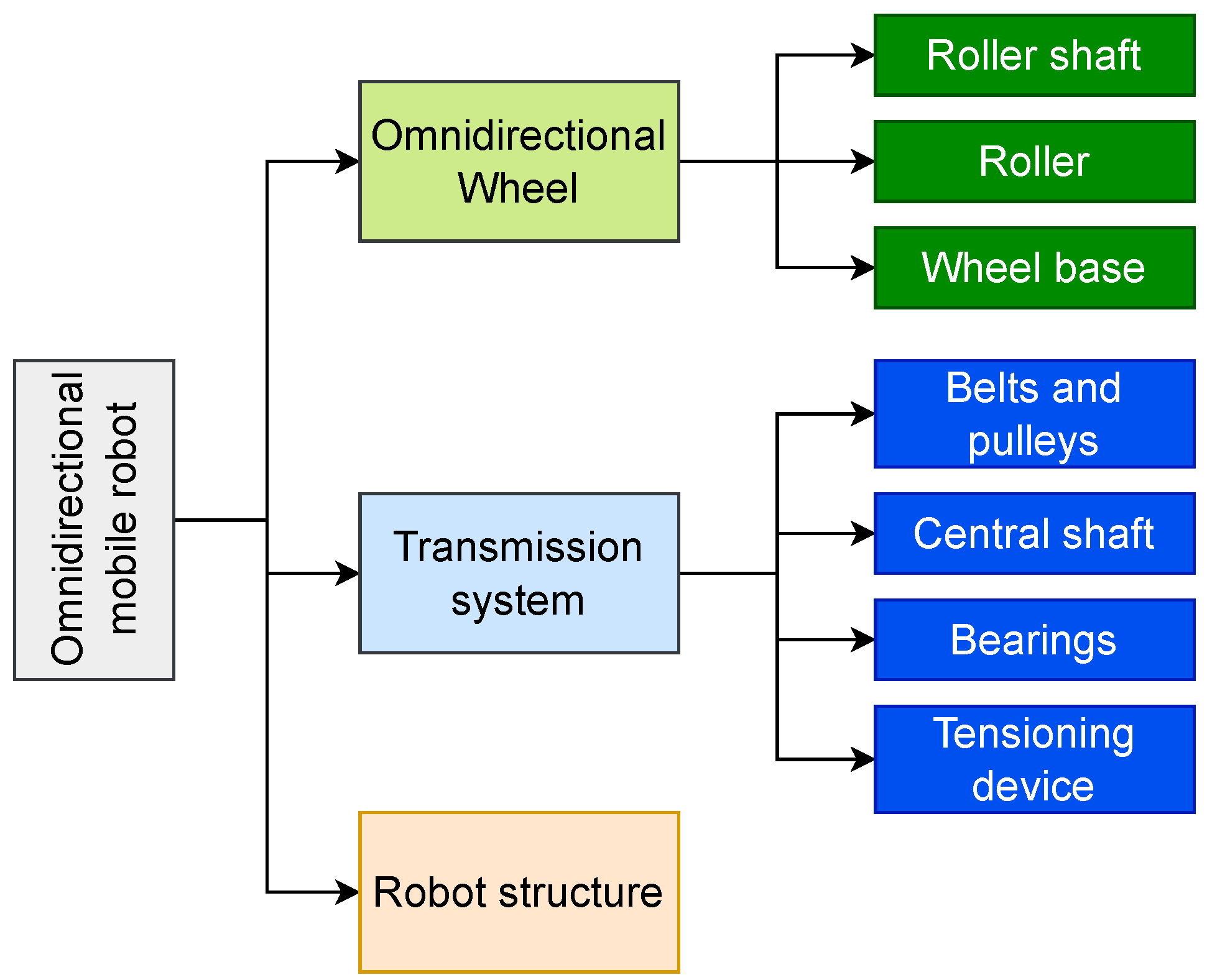
In this section, the design of the wheels is considered, taking into account the specifications that this element must comply with, followed by its transmission system. Then, proposals are made on the main shape of the platform body that will house the motors, gearboxes, and power adapters. Finally, a structural analysis of the platform body and its constituent parts is carried out, taking into consideration that one of the goals to be achieved is to reduce the weight of the platform. The following scheme of
Figure 12 summarizes the contents of the section.
Figure 11.
Workflow of the mechatronic design process.
Figure 11.
Workflow of the mechatronic design process.
Figure 12.
Mechanical design schematic.
Figure 12.
Mechanical design schematic.
5.1.1. Omnidirectional Wheel Design
The design process consists of the static and dynamic analyses, as well as the calculation of the stresses of each component. The load to be supported is 300 kgf as established by the objective required by the sponsor, but an estimated value of 100 kgf must also be added, which represents the dead load of the structure. Therefore, the total value to be supported is 400 kgf, and it will be divided among the three wheels.
Based on existing designs such as HANGFA Robotics QLM Series (
https://www.hangfa-europe.com/en/mecanum-wheels/qlm-series [accessed on 29 April 2025]) omnidirectional wheels, we opt for an initial diameter of 200 mm, similar to the 203.2 mm used by QLM Series omnidirectional wheels. This design incorporates twelve polyurethane rollers with an aluminum body and a load capacity of 160 kgf per wheel. In comparison, the mecanum wheels [
26], while offering higher precision in motion due to optimized parameters such as the angle between the roller axes and the wheels (45°) and a more advanced roller design, present manufacturing complexities and higher costs. Our approach prioritizes the ease of construction and less need for complex adjustments, while maintaining adequate load capacity and sufficient functional characteristics for the proposed mobile system.
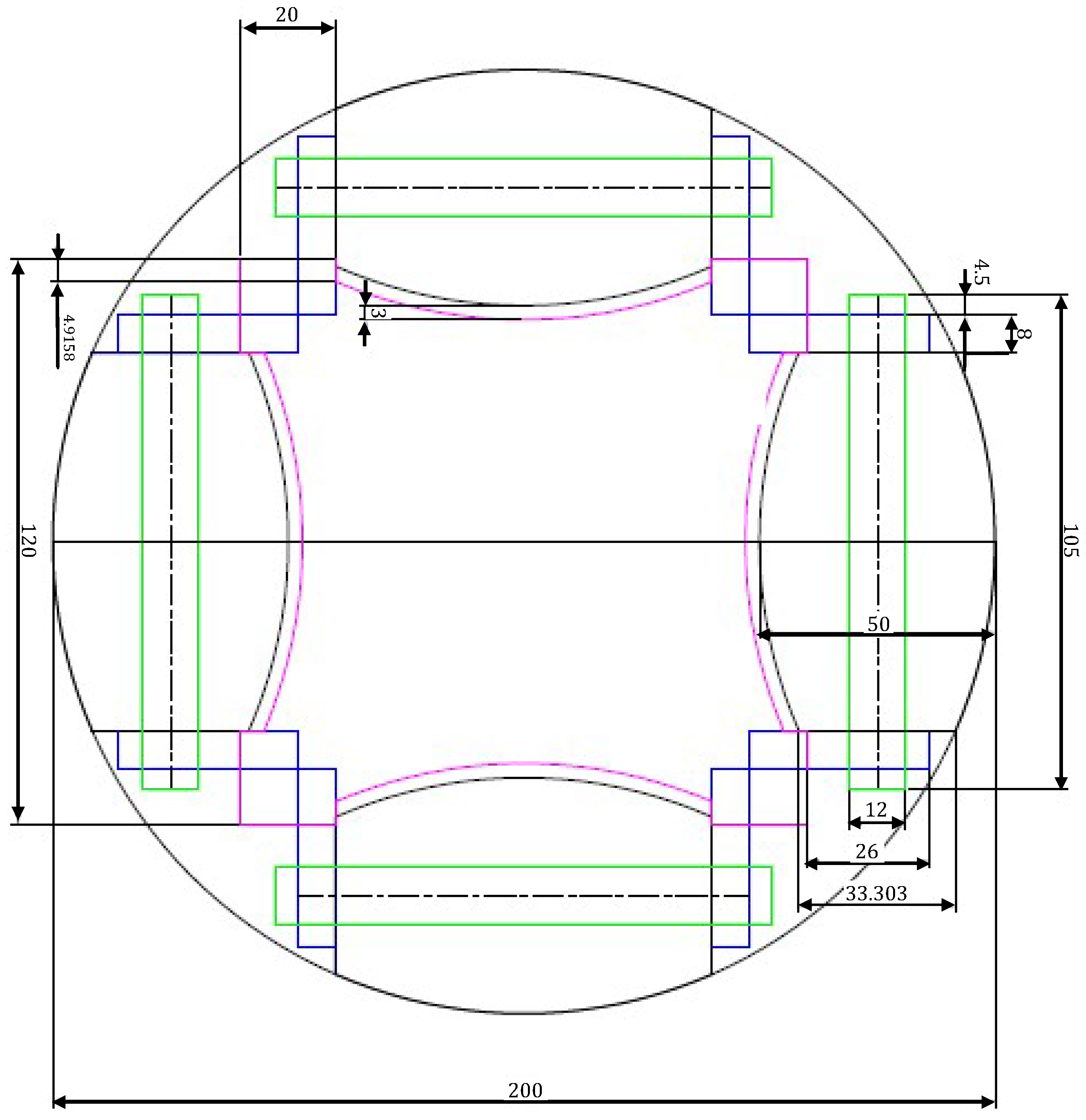
The first step is to know the diameter of the roller axle, for which a length is estimated from a geometry-only design, using AutoCAD 2023 software and manipulating the dimensions in millimeters until a perfectly symmetrical wheel geometry is obtained as shown in the following
Figure 13.
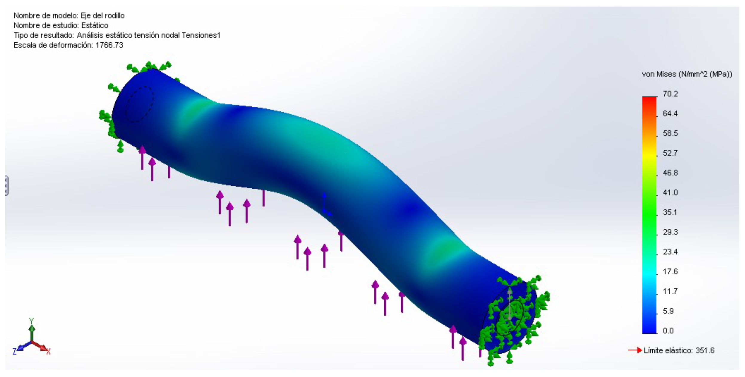
Static study performed in SolidWorks 2023 to determine von Mises stress distribution. The arrow indicates the applied load direction. The corresponding value is shown in the following
Figure 14.
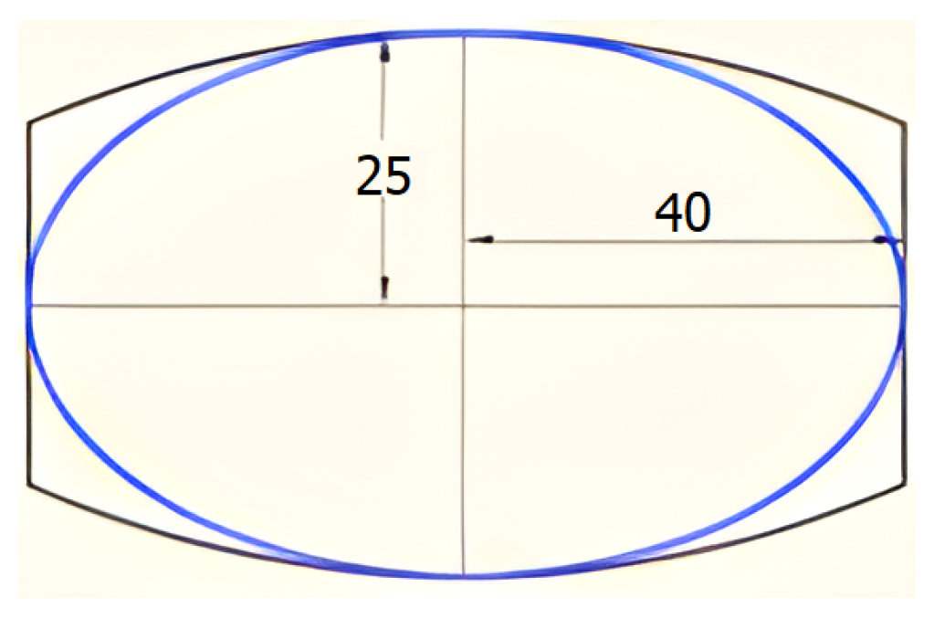
As can be seen from the results, the maximum stress is 70.2 MPa, without exceeding the allowable stress of 351.57 MPa, giving a reliable safety factor. Continuing with the wheel design, an important component is the roller because it adds a third degree of freedom, turning a conventional wheel into a omnidirectional one. The roller has a special ellipsoidal cylinder shape. In order to obtain a closer approximation to the actual geometry of the roller, the stresses exerted on an ellipsoid pressed from Duralon on a concrete plane are analyzed. The dimensions of the semi-axes of the ellipsoid are 25 mm and 40 mm as shown in
Figure 15.
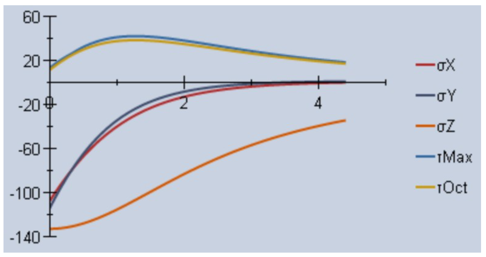
Evidently, the geometrical form that comes closest is the ellipsoid. There is a program called “Mesys Hertzian Stress” that shows all the stresses and data that are calculated in spherical, cylindrical, and elliptical contact exercises as seen in
Figure 16. The program shows the evolution of the variables with respect to the central Z-axis.
The stress that has the highest σZ value is −133.55 MPa which, due to its sign, works in compression. Duralon has a compressive strength of 55 MPa, and is a material that, due to its own characteristics, tends to fail by wear.
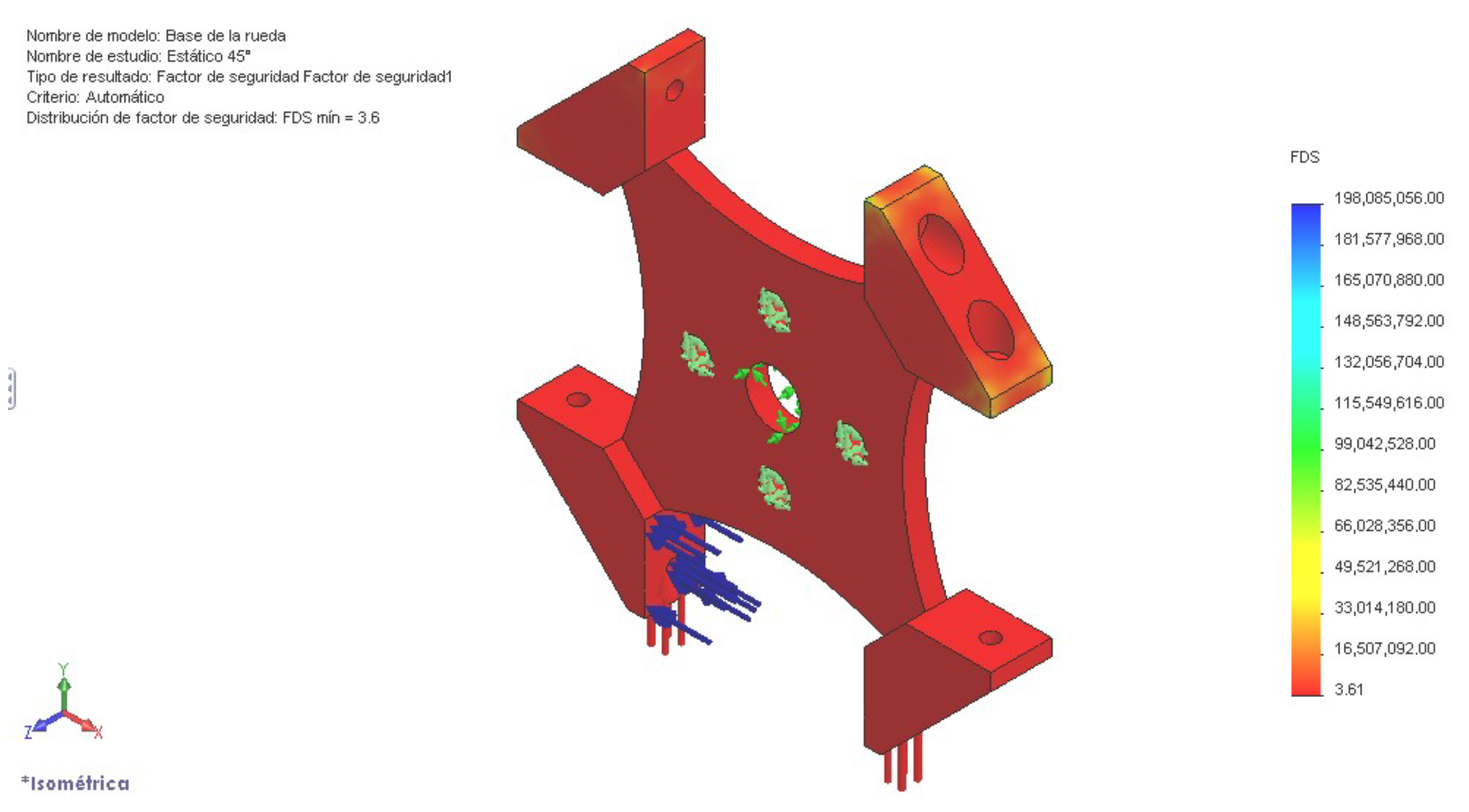
Finally, we have the base of the omnidirectional wheel that will be under the bending effect in the supports (blue arrows in
Figure 17). The safety factor is determined by means of the finite element analysis.
A reliable and ideal safety factor of 3.6 is obtained, reducing the weight of the wheel. However, the cost of machining that would result from reducing the thickness in the central body of the plate from 22 mm (due to the supports) to 8 mm would be high. Therefore, it is decided to manufacture it in two parts, known as support and plate for the bases, to be later joined by welds.
5.1.2. Transmission System
This system is the essential element for the transmission of motion. It is designed to reduce the speed and increase the torque at the output (wheel). This system is composed by two pulleys, each one attached to a shaft and adjusted by means of a belt. As such, it is a very quiet system, does not require lubrication, is inexpensive to build, and can be used as a mechanical fuse. There are several types of belts. In this case, it is necessary to use synchronous belts to guarantee no slippage between the belt and the pulley [
27].
Given that the presented platform is currently at the prototype stage, the use of a synchronous belt transmission is primarily chosen for its simplicity, ease of implementation, and low manufacturing costs. This decision allows for rapid development and iterative testing without compromising the overall performance objectives.
In addition, recent studies support the effectiveness of synchronous belt systems in robotic applications. Liang et al. [
28] demonstrated that a synchronous belt servo system improved vibration absorption and torque transmission capabilities in skid–steer mobile robots. Similarly, Zhao et al. [
29] successfully employed belt-driven transmission mechanisms in Delta robots actuated by stepper motors, achieving high levels of precision and efficiency in trajectory tracking tasks.
With respect to the central axis of the wheel, the maximum stress is 96.53 MPa, and the fatigue factor 1.94 is determined, being acceptable for a diameter of 30 mm and a shoulder of 35 mm. The ball bearings with the following characteristics, inner diameter 30 mm and outer diameter 72 mm with a width of 19 mm, give a reliability of 0.987.
5.1.3. Platform Structure
The structural design of the omnidirectional platform focuses on achieving a robust, lightweight, and modular architecture, capable of supporting significant loads without compromising stability or maneuverability. The structure is developed using standard aluminum T-slot profiles, selected for their high strength-to-weight ratio, modularity, and ease of assembly. The design process is divided into three main components:
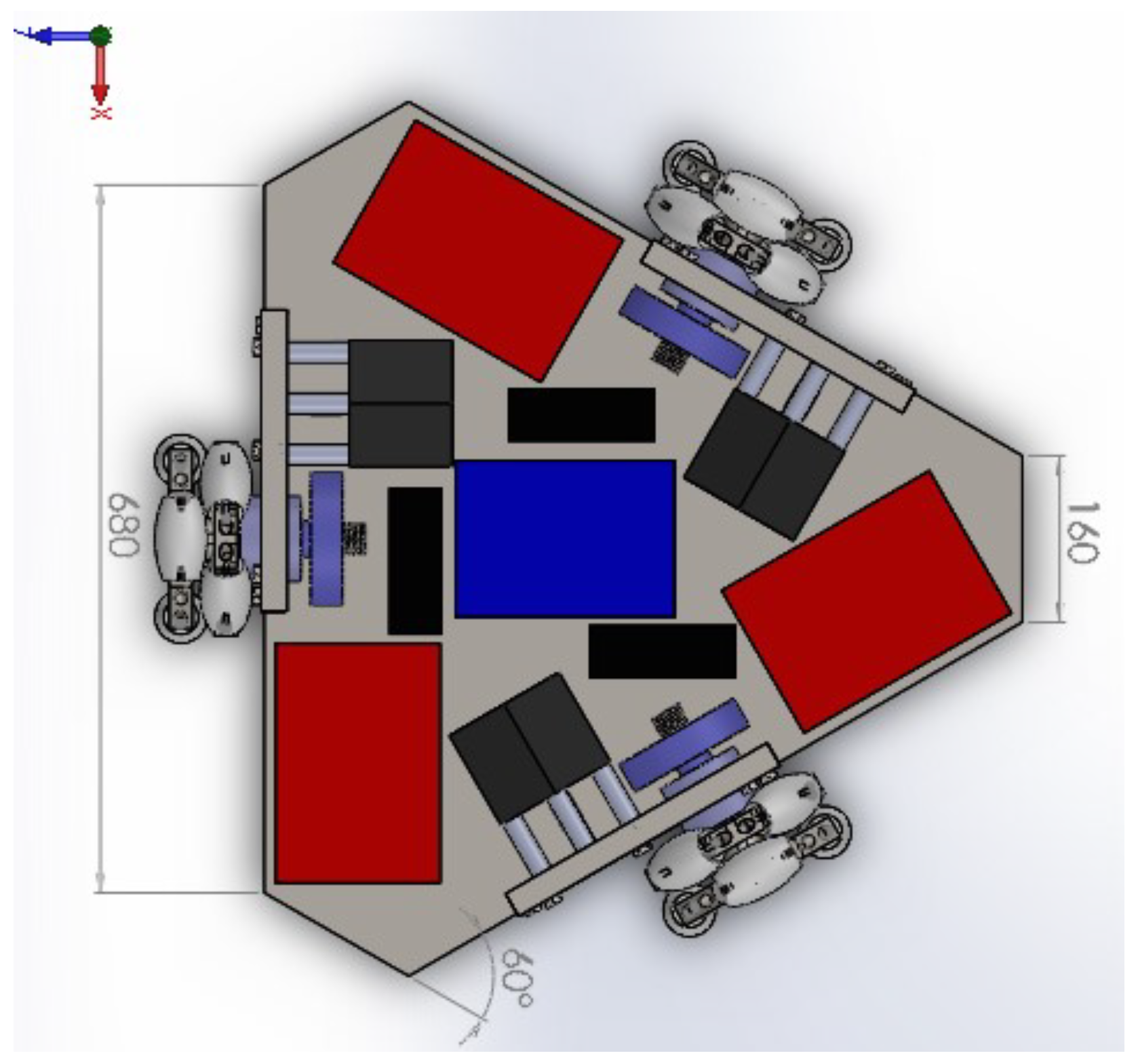
Lower Frame: Based on the design study presented in
Section 3, the lower frame adopts a rigid triangular geometry that supports the 3A configuration, with dimensions optimized to accommodate both the transmission systems and the electronic components as shown in
Figure 18.
The structural framework of the lower base is built using steel Tee profiles, arranged from the geometric center outward toward each lateral centerline, effectively channeling operational loads and reactions directly through the main structural paths.
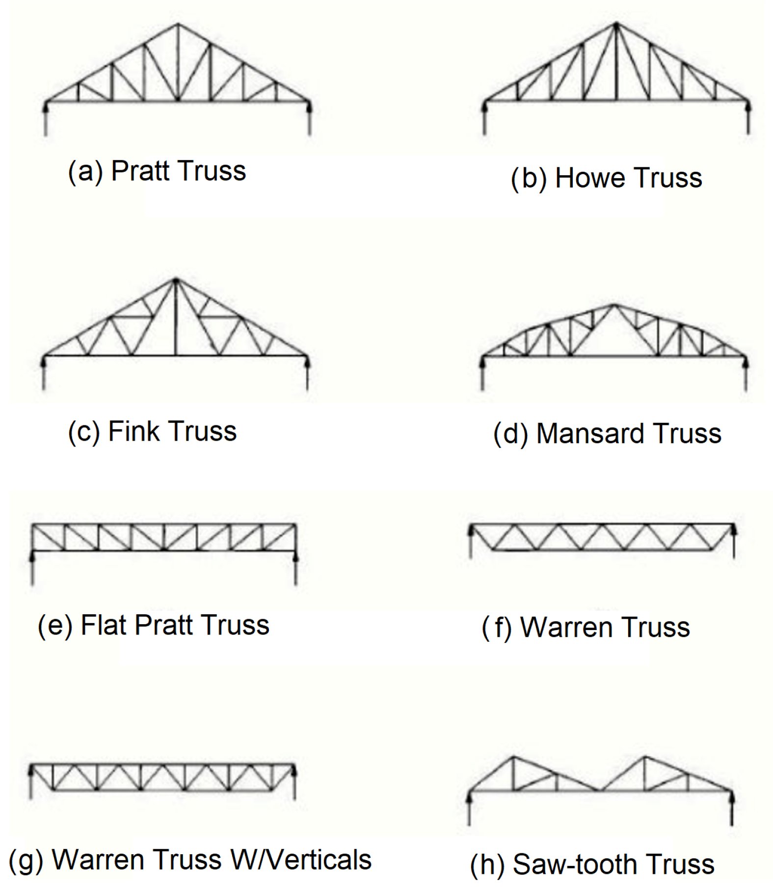
Vertical Structure: The vertical supports connecting the lower frame to the upper platform are designed using a Warren truss configuration with verticals (option g,
Figure 19). The classic Warren truss is characterized by equilateral triangles, where members are subjected to pure compression or tension, and where the diagonal elements have identical lengths. This geometry results in an efficient distribution of internal forces and provides an excellent weight-to-span ratio, particularly advantageous for short spans such as those encountered in the platform.
The incorporation of vertical members further enhances the performance of the structure under non-uniform loading conditions. In the Warren truss with verticals, vertical elements handle shear forces more effectively, allowing diagonal members to maintain primarily axial loads (compression or tension). This reduces bending stresses and local deformations under dynamic operational conditions, such as acceleration, deceleration, and maneuvering with heavy loads.
Additionally, using members of identical length simplifies manufacturing and assembly processes, reducing construction costs and ensuring consistency in mechanical behavior across all sections [
30].
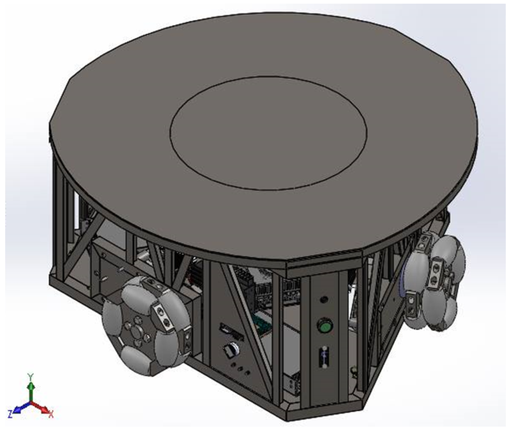
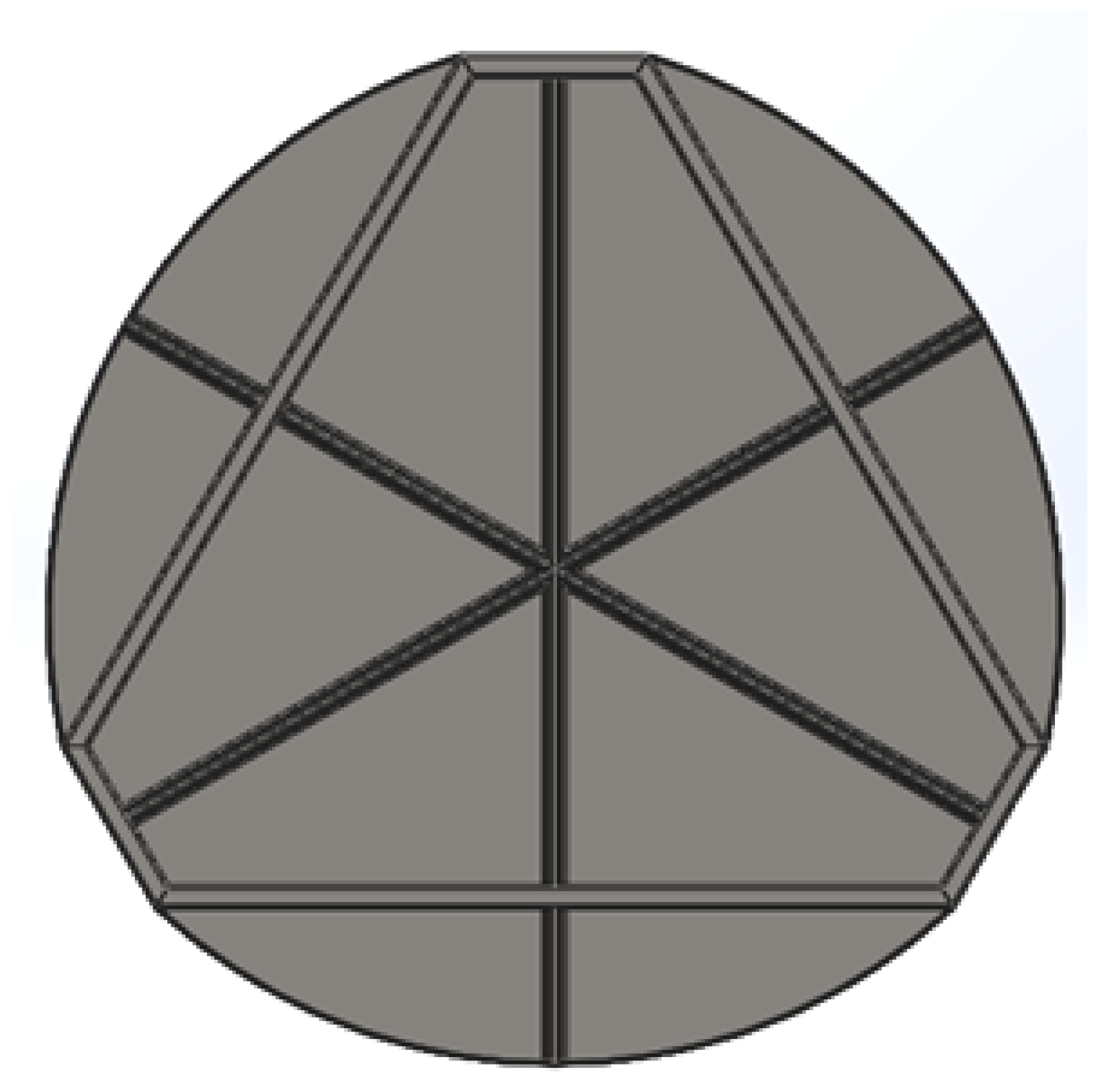
Upper Platform: To maximize the available area for payload accommodation, the upper platform is designed to approximate a circular geometry with a diameter of 1 m, despite the underlying triangular configuration of the main structure.
This design choice provides a larger and more uniform surface, facilitating the placement and securing of bulky loads, and improving the overall usability of the platform for industrial material handling tasks.
Structurally, the platform consists of a top-mounted non-slip steel plate, serving as the primary load-bearing surface where the cargo is placed. Underneath this plate, a reinforcing substructure of Tee profiles is arranged radially and orthogonally as shown in
Figure 20, which depicts the underside view. The reinforcement is concentrated at the center, where the highest stresses due to load concentrations are expected, ensuring that the plate can maintain structural integrity under operational conditions.
The modular profile-based construction allows easy adjustments and potential future expansions of the system, facilitating maintenance and reconfiguration for different industrial tasks.
This design approach ensures that the platform could transport loads up to 300 kgf while maintaining mechanical reliability, minimizing structural vibrations, and preserving operational stability on industrial surfaces.
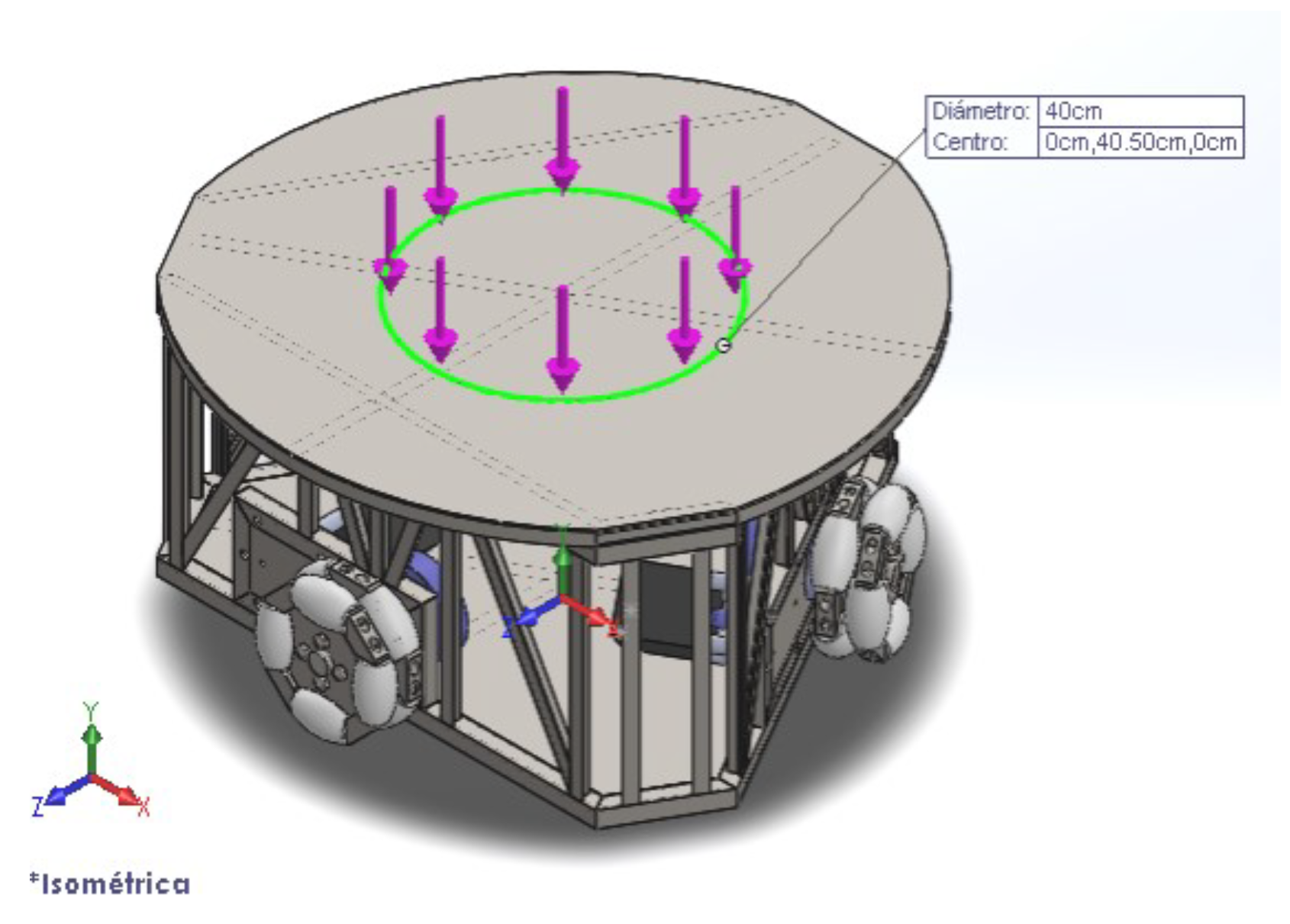
However, three-wheeled omnidirectional robots have a natural balancing issue because their support points form a triangle. This can be a challenge, especially when the robot is climbing a ramp or has a high center of gravity. To prevent the robot from tipping over, it is important that the load is kept within a safe area, with a maximum radius of 20 cm from the center of the platform as depicted in
Figure 21. The arrow in the figure indicates the direction of the load. This helps to maintain balance and ensures that the robot can move smoothly, even on inclined surfaces.
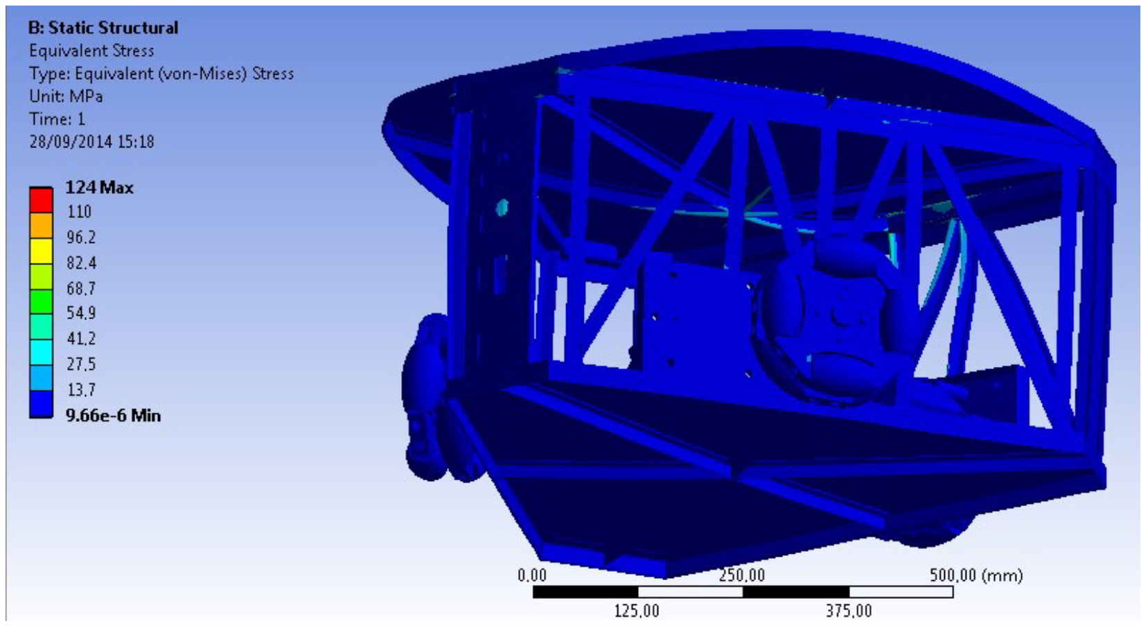
ANSYS 2023 R2 software is used for the FEM analysis.
Figure 22 shows that the affected zone where this stress is concentrated is the Tees of the cover (light blue). The maximum stress supported by the structure is 124 MPa (red, inside the light blue zone, occluded).
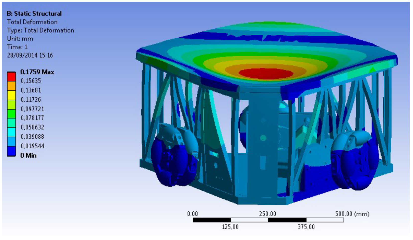
In terms of deflection, the largest deformation is equivalent to tenths of millimeters, being barely 0.18 mm as shown in
Figure 23 (red). This deflection is at the top of the structure.
The safety factor regarding stress is very safe, reaching a value of 2 as seen in
Figure 24. The most critical part of the structure is located in the columns (vertical Tees).
5.2. Control and Simulation System
This section presents the implementation of a control system that allows the interpretation and execution of PTP and CP instructions, fundamental for the generation of movements of the omnidirectional mobile robot. These instructions are designed to specify trajectories and motions based on key parameters, such as the initial and final coordinates (X,Y), the type of trajectory (curved or linear), the velocity v, and acceleration a of the robot. The different ways of encoding the trajectories are detailed below:
Linear trajectory: This instruction allows to perform a rectilinear displacement between two points defined by initial and final coordinates, considering constant velocity and acceleration:
Curved path: It specifies a curvilinear motion defined by a radius
r, direction of rotation clockwise + or counterclockwise −, and velocity and acceleration parameters:
Rotate around its own axis: It allows rotating the platform around its central axis, specifying a rotation angle
, angular velocity
, and angular acceleration
:
Wait time: The robot pauses its operation for a time
t specified in seconds, useful for synchronization with other tasks.
Once the parameters associated with the instructions are extracted and assigned to their respective global variables, an algorithm is implemented to convert them to local variables, ensuring modularity and encapsulation of the code. From these variables, the kinematic and dynamic matrices developed in
Section 4 are applied to calculate the angular positions of the wheels according to the desired motion.
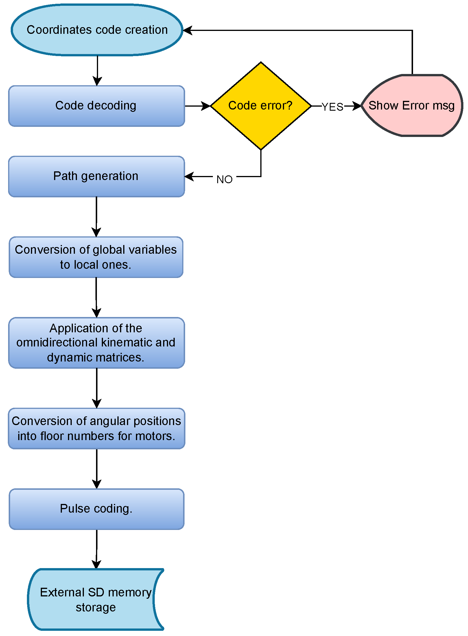
Subsequently, the angular positions are transformed into numbers of steps required for the stepper motors. This process includes the generation of signals by pulse coding, ensuring precision in the execution of the movements. Finally, all the generated information is stored in an external memory (SD card), which allows recording and analyzing the system behavior for future optimizations.
This process is visually described in the flow diagram shown in
Figure 25, which illustrates the sequence of operations from the interpretation of the commands to the execution of the movement on the robotic platform.
Stepper Motor Control Algorithm
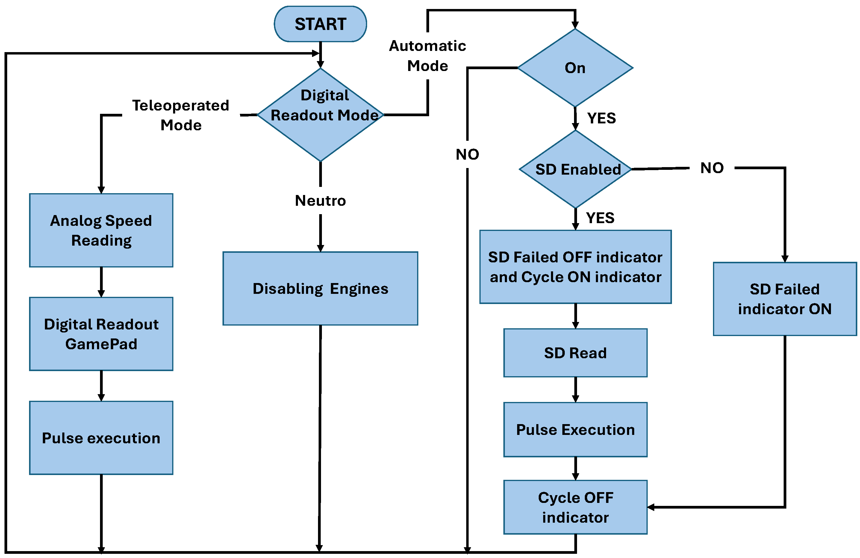
Within this operation, the user first generates a .txt file with the code of the coordinates. The Matlab program is executed and subsequently outputs a new .txt file containing a group of characters to be interpreted by the microcontroller. The next step is to insert the SD into the slot and then press the “2” button, which represents the cycle start. A “Cycle in Process” indicator will light up when the cycle is running, and will turn off when the cycle is finished. If there is a case where the SD is not inserted, an “SD Read Failed” indicator will light up. The internal workflow of the stepper motor control algorithm is depicted in
Figure 26.
Figure 25.
Algorithm flow diagram.
Figure 25.
Algorithm flow diagram.
Figure 26.
Flow diagram of the microcontroller algorithm.
Figure 26.
Flow diagram of the microcontroller algorithm.
5.3. Electronic and Electrical System
For this section, it is necessary to determine three important parameters: torque, power, and speed. Based on the mechanical analysis presented in the previous sections, with a reduction ratio of 4:1, the minimum torque required from the stepper motors is 9.25 Nm. Regarding speed, through iterative testing with the microcontroller, it is established that the motor can reach a maximum of 300 rpm with 200 pulses per revolution.
The selection of stepper motors for the omnidirectional mobile platform is based on several technical considerations:
Precision and open-loop control: Stepper motors allow for precise position control without the need for feedback systems, simplifying the control architecture.
Ease of implementation: Their inherent ability to operate in open-loop mode reduces system complexity and facilitates maintenance and troubleshooting.
Cost and availability: Stepper motors are widely available and cost effective, making them ideal for prototype development and industrial applications where budget constraints are important.
These characteristics make stepper motors particularly suitable for omnidirectional mobile platforms that require precise and repeatable movements. This selection is supported by recent studies. For example, Zhao and Hwang developed an autonomous indoor navigation platform using stepper motors, emphasizing their precision and ease of control in constrained environments [
31].
Similarly, Simerean and Tătar presented a tetrahedral mobile robot with omnidirectional locomotion units, employing stepper motors to achieve precise multi-directional movements [
22].
To further justify the selection of stepper motors for the omnidirectional mobile platform,
Section 5.3.1 presents a comparative analysis between stepper motors and servomotors. This comparison evaluates key aspects such as control complexity, precision, cost, and performance, reinforcing the suitability of stepper motors for the current prototype requirements.
The following
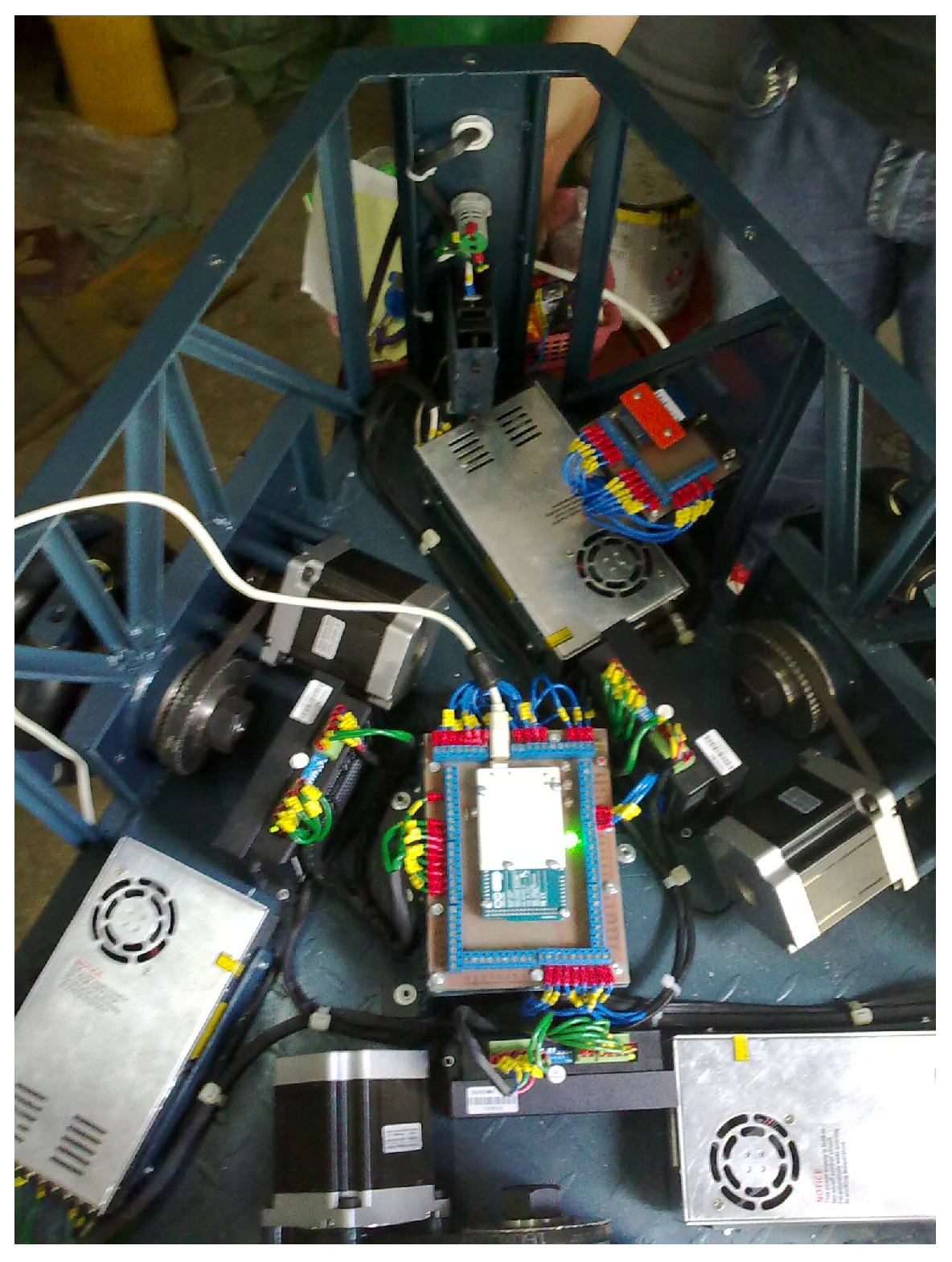
Figure 27 shows the layout of the electronic components inside the body of the omnidirectional mobile robot, including the power source assemblies, the drivers for the stepper motors and the Arduino Mega. This layout has been designed to optimize the available space, facilitate access to the electrical connectors, and minimize interference between the different modules, thus ensuring the efficient and safe operation of the system.
5.3.1. Stepper Motor
Actuator selection plays a crucial role in the design of mobile robots. Two of the most commonly used motors in these applications are compared below (
Table 4).
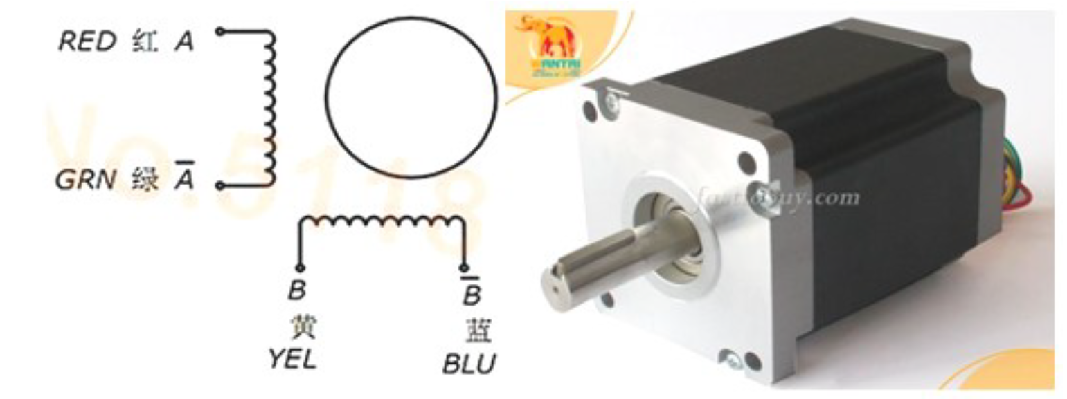
The stepper motor (
Figure 28) is selected basically due to its ease for control. This ease for control is beneficial since the positioning of three motors must be controlled in parallel. The prototype uses three motor, driver, and source assemblies. The implementation of these motors in our application is performed by working together with the speed reduction system.
When controlling any stepper motor, it is necessary to generate a certain sequence of pulses [
33]. The present controller performs that sequence by means of two inputs, pulse and direction, where each rising edge on the pulse pin means an angular variation according to a pulse configuration given in the driver.
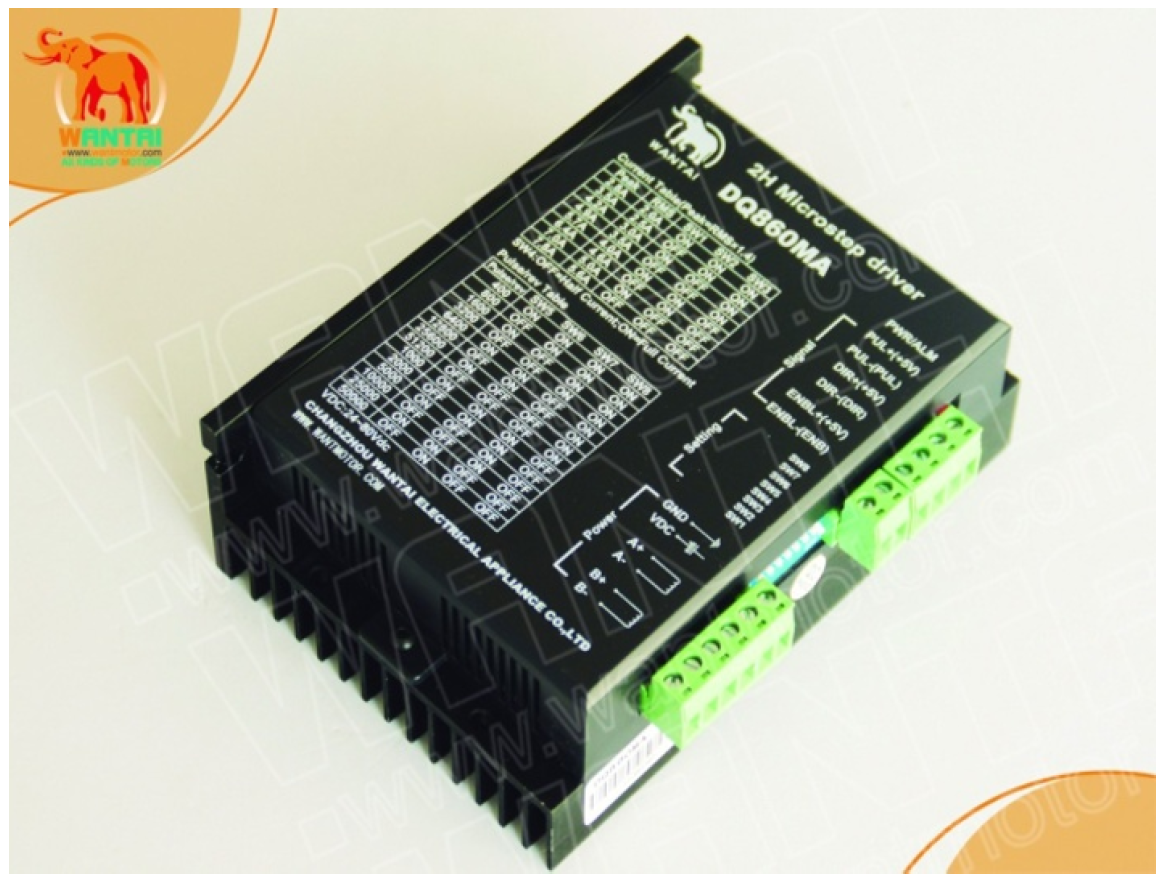
DQ860MA (
Figure 29) is a two-phase hybrid stepper motor controller [
34]. Its driving voltage ranges from 24 VDC to 80 VDC. The circuit it adopts is similar to a servo control circuit, which enables the motor to run smoothly, almost without noise and vibration.
Features:
High performance, low price.
Opto-isolation I/O signal.
Over-voltage, under-voltage, over-current and short-circuit protection.
Motor torque is related to speed, but not related to step/revolution.
High starting speed.
High holding torque.
5.3.2. Microcontroller
A fundamental advantage that Arduino has is the ease of programming that it provides. On the other hand, the Arduino electronic board is a board designed to facilitate the use of electronics in multidisciplinary projects.
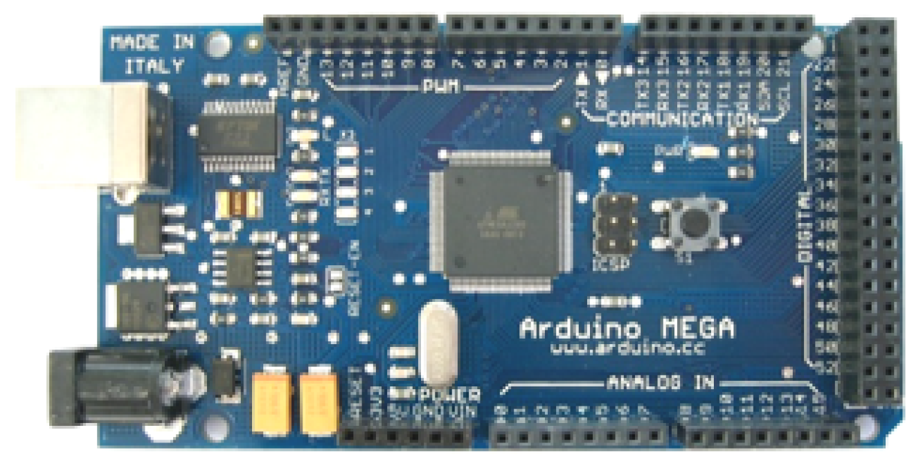
Throughout the development of the platform, the need to command several inputs and outputs is seen, from where the Arduino Mega satisfies this need. The Arduino Mega (
Figure 30) is an electronic board based on the Atmega1280 microprocessor. It has 54 digital input/output pins (of which 14 can be used as PWM outputs), 16 analog inputs, and a 16 MHz ceramic resonator.
6. Experiments and Results
This section presents the experiments performed to validate the kinematic and dynamic model of the mobile robot platform, as well as the results obtained. In addition, the stepper motor control is included, with the purpose of obtaining the respective pulses for the stepper motors of the three-wheeled omnidirectional mobile robot.
The first
Section 6.1 describes the algorithm developed to calculate the parameters of the kinematic and dynamic equations from a predefined trajectory, which allows the theoretical behavior of the system to be evaluated. On the other hand, the second
Section 6.2 presents two real tests: one in which the robot operates in automatic mode following the generated trajectories, and the other in teleoperated mode, thus allowing to compare its theoretical performance with the real behavior in a physical environment.
6.1. Experiments and Results with Kinematic and Dynamic Model
The diagram of
Figure 25 of
Section 5.2 summarizes the procedure which is followed for the programming. The explanation of this part will focus on the five following points:
Generation of the trajectory , and ;
Conversion of global variables M to local ;
Application of the kinematic and dynamic matrices to obtain the angular positions and torque of each wheel;
Conversion of angular positions into step numbers for motors;
Simulation and graphical presentation of the speeds, torques, and powers of each wheel.
The following is an example set of the PTP and CP instructions to detail the coordinates to be followed by the platform. This example set of instructions is selected such that a closed trajectory should be generated:
| line 2 0, 0.2 0.04 |
| circ 3 1 1 +, 0.1 0.05 |
| rotate 45, 0.2 0.4 |
| line 3 2, 0.2 0.04 |
| circ 2 3 1 +, 0.15 0.04 |
| rotate 90, 0.2 0.4 |
| line 1 3, 0.2 0.04 |
| circ 0 2 1 +, 0.15 0.04 |
| rotate 180, 0.3 0.4 |
| line 0 0, 0.2 0.04 |
| wait 2 |
| rotate 0, 0.3 0.4 |
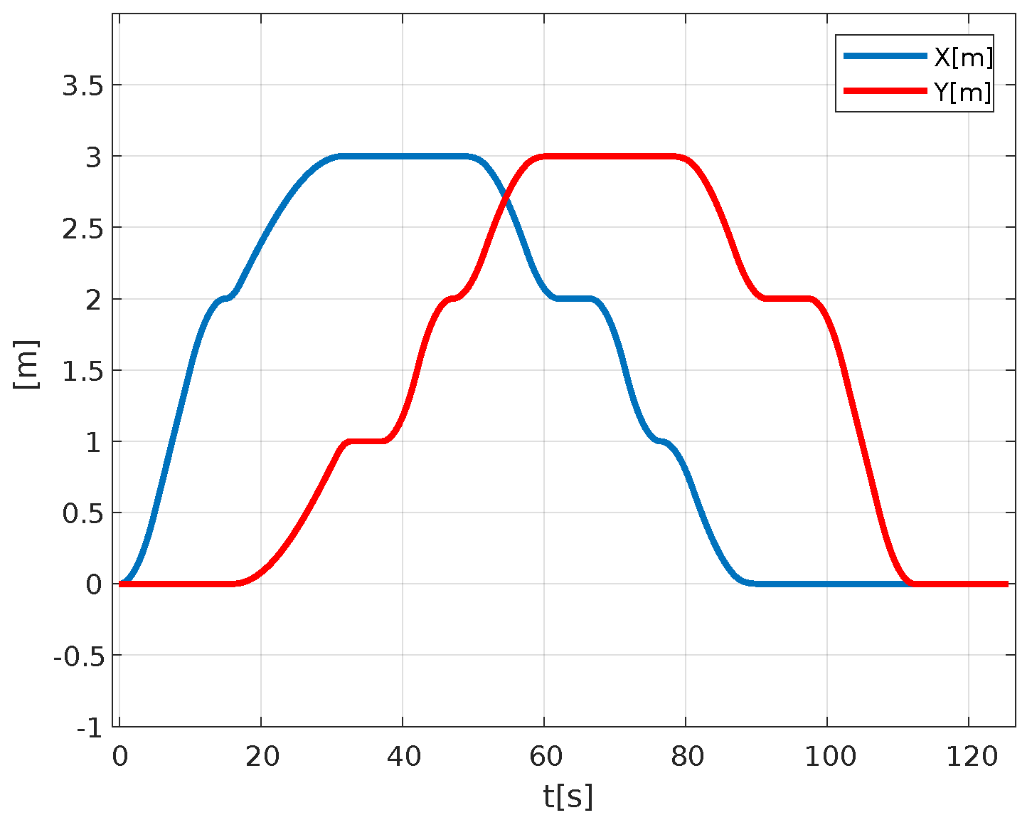
The first graph of
Figure 31 shows the X and Y coordinates of the trajectory, as a function of time.
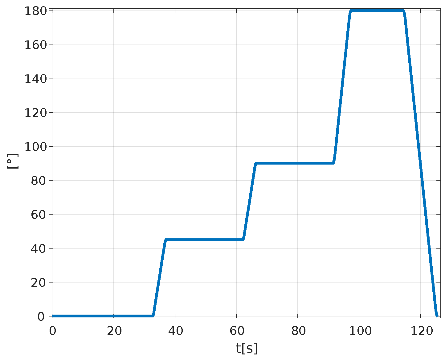
Figure 32 shows the angular component of the trajectory as a function of time.
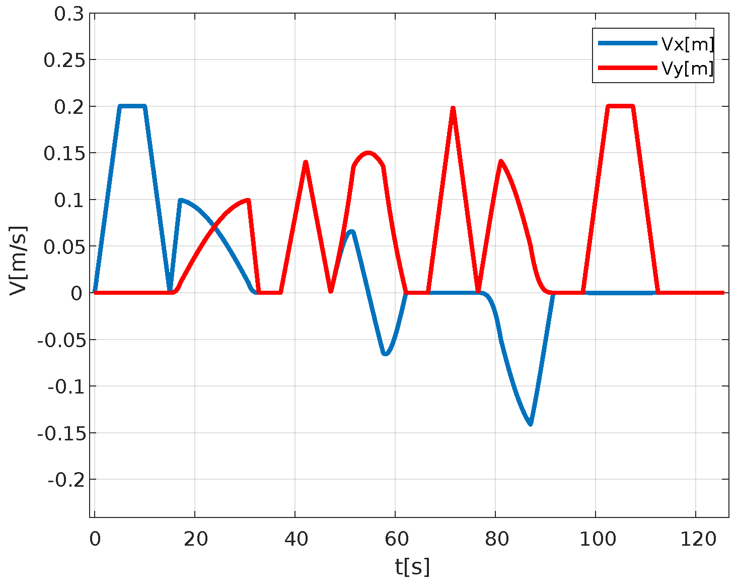
Figure 33 shows the graphs of the velocities in the X and Y coordinates of the platform as a function of time, compared to the desired trajectory. In this graph, we can appreciate the ranges of uniformly accelerated, uniform rectilinear, and decelerated motion.
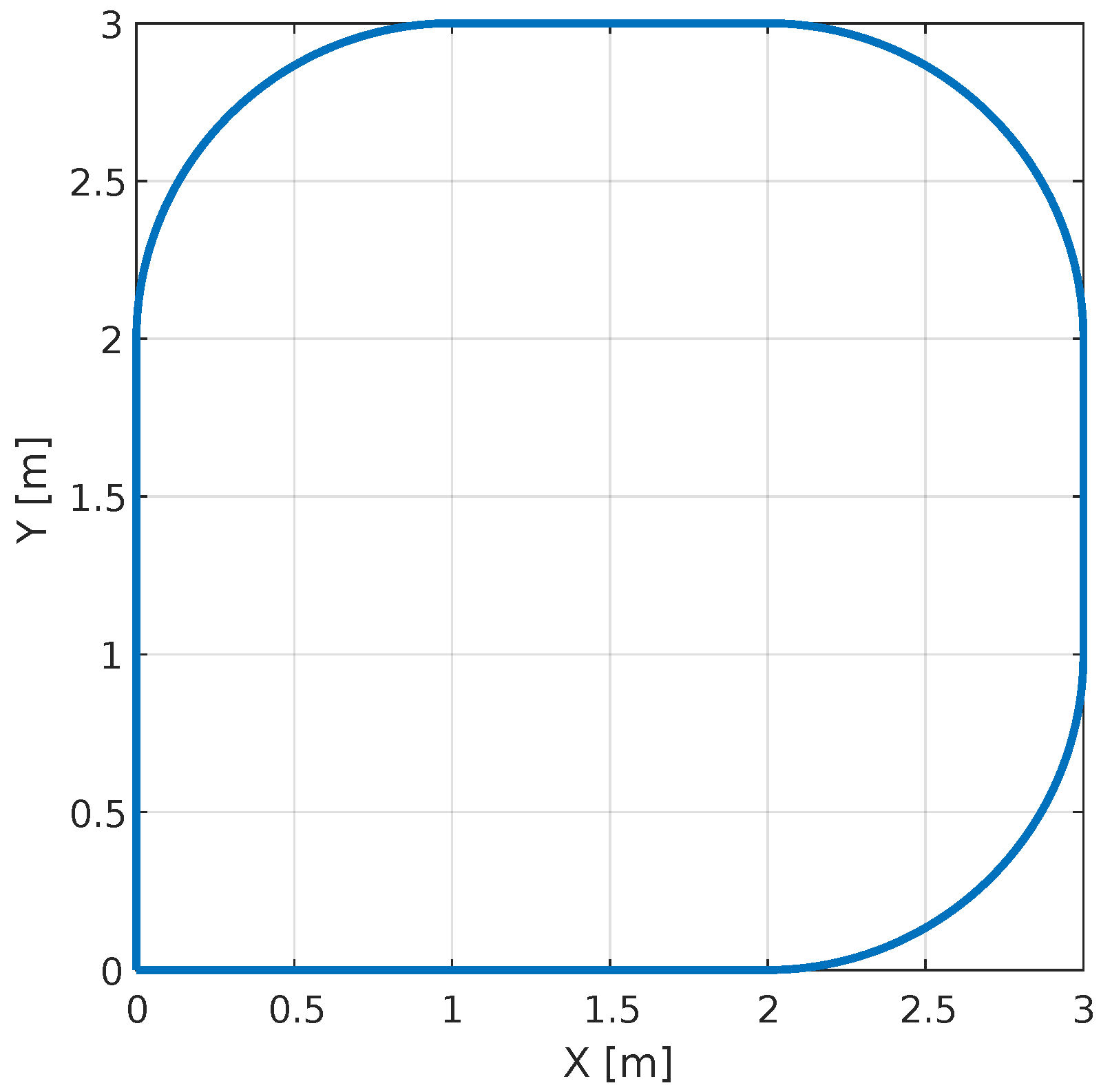
Now for the case where the path of the platform complies with the coordinates written by the user is checked, see
Figure 34.
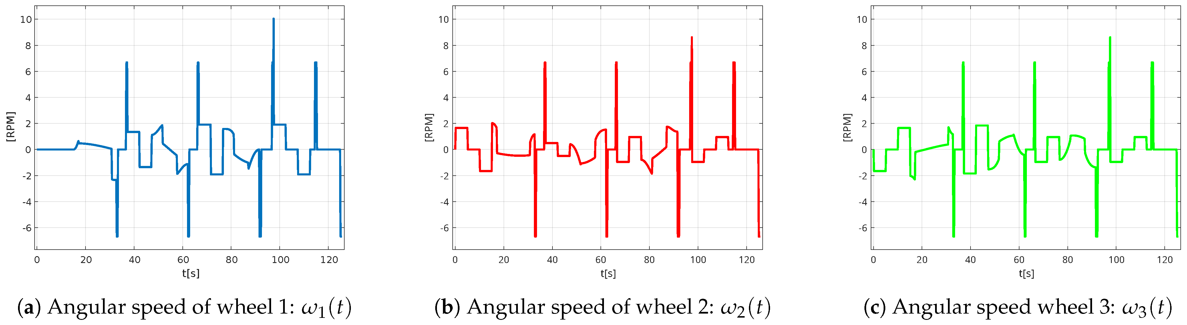
Now with respect to kinematics, the following graphs (
Figure 35) show the angular velocities of each wheel.
With the trajectory set by the user, wheel 1 has maximum speeds of 10 rpm and 9 rpm on wheel 2 and wheel 3.
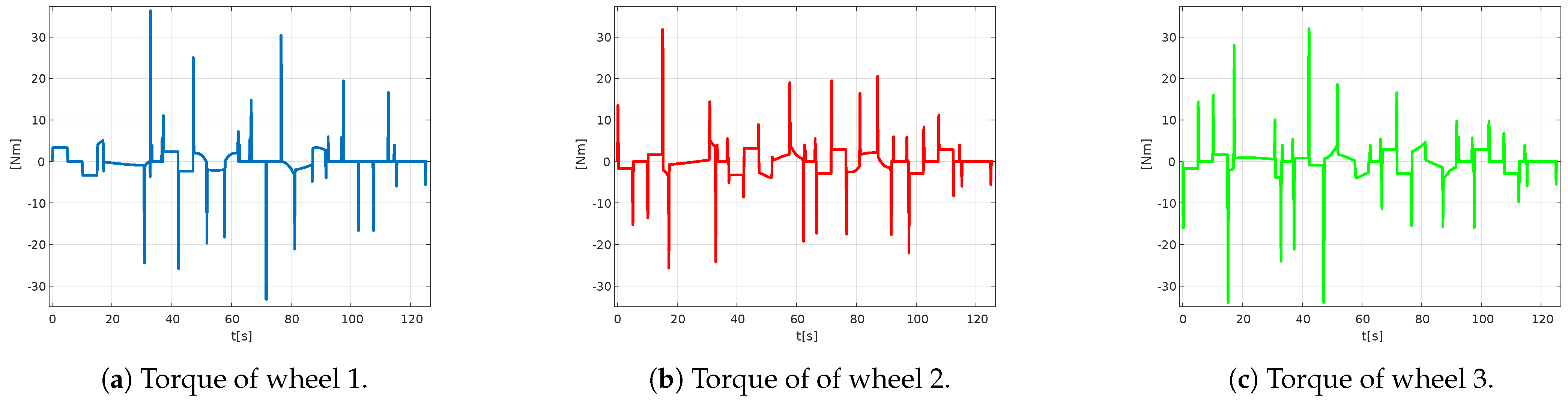
Figure 36 shows a maximum torque value of approximately 37 Nm generated by the motor on wheel 1, 32 Nm on wheel 2, and a torque of 34 Nm on wheel 3.
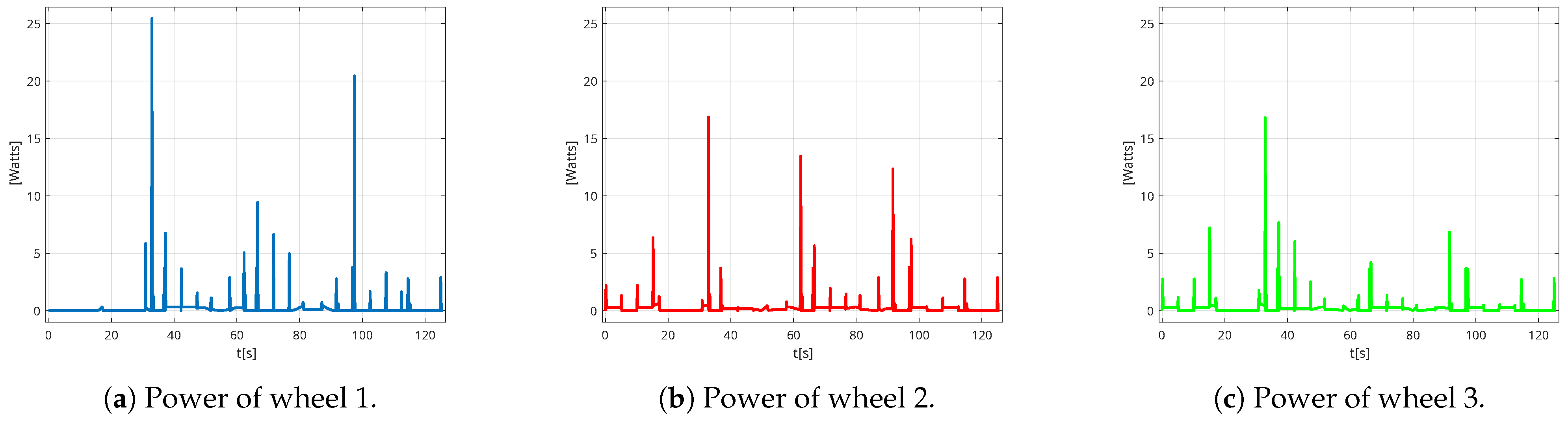
Finally, the power of each motor is plotted according to the established trajectory in
Figure 37. The motor of wheel 1 generates a maximum power of approximately 26 W, the maximum power of motor 2 is approximately 17 W, and finally the motor of wheel 3 generates a power of approximately 17 W.
In conclusion, in this trajectory, the following values are obtained in general: a power of 26 W capable of rotating at 10 rpm to exert a torque of 37 Nm.
6.2. Experiments and Results with Mobile Robot Platform
The experimental tests performed allow evaluating the performance of the mobile robot platform in a real environment, verifying the accuracy and efficiency of the system when executing the generated trajectories. For this purpose, two test modes are considered: one in automatic mode, where the robot follows the planned trajectories, and the other in teleoperated mode, where the control is exercised manually. The analysis of the results obtained in both tests allows contrasting the theoretical operation with the practical performance of the system, identifying possible improvements and adjustments in the design and control of the robot.
The procedure to be followed by the operator for the implementation of the omnidirectional movement control of the platform is shown in the diagram in
Figure 26.
6.2.1. Automatic Mode
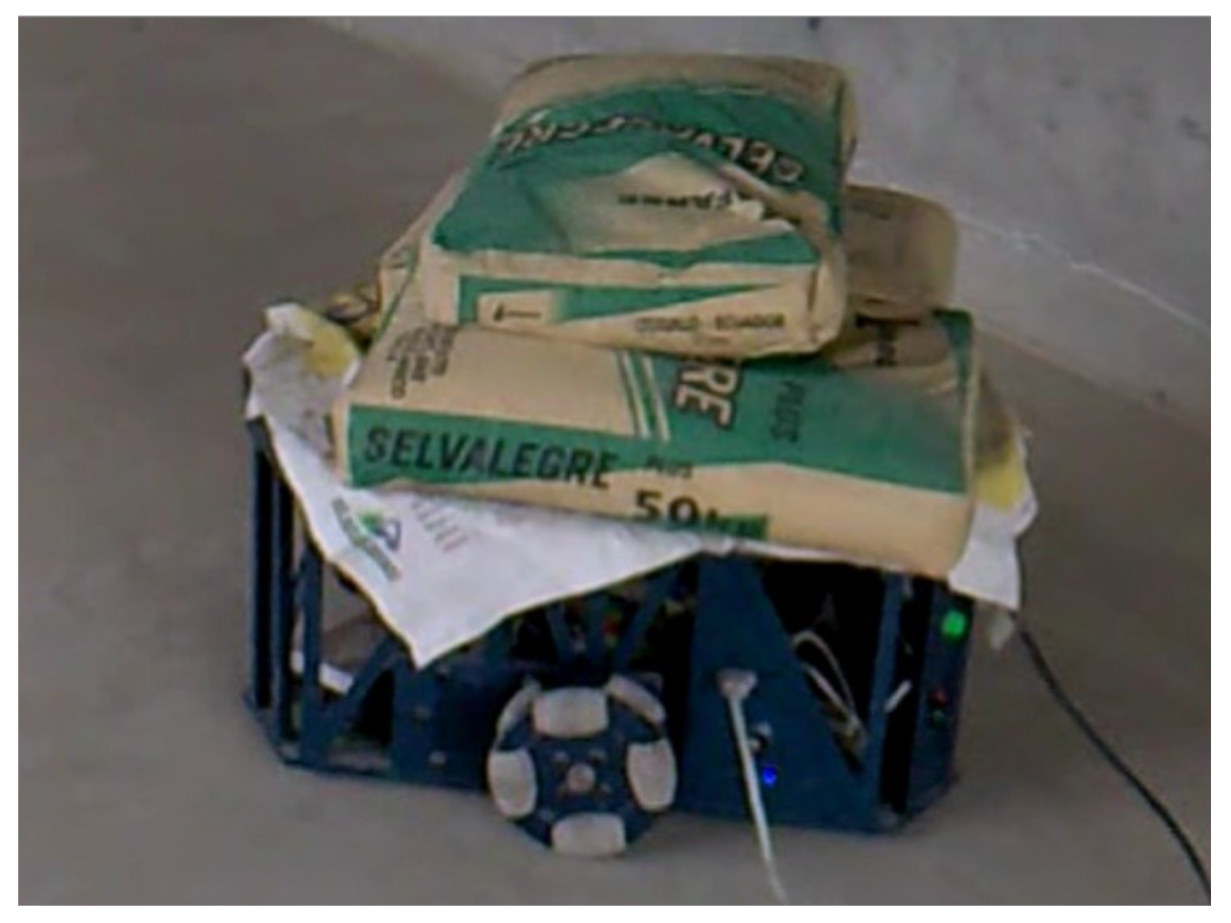
For this test, increasing loads of 50 kgf (e.g., 150 kgf as shown in
Figure 38) are applied to the platform, and the following observations are obtained.
In this test, it is determined that the maximum capacity to be moved by the platform in automatic mode is a load of 150 kgf as depicted in
Table 5.
For all the tests, the driver is configured at 400 pulses/rev, at driver full current (SW4 ON) and at maximum output current peak 7.80 A and RMS 5.60 A. For this automatic mode test, the platform reaches a maximum wheel speed and torque of 10 rpm and 36 Nm as illustrated in the simulation.
As part of the performance evaluation in automatic mode, the payload fraction (Ratio) of the platform is calculated. In this mode, the platform successfully transports a load of up to 150 kgf, while the approximate self-weight of the platform is 100 kgf. Thus, the payload fraction achieved during automatic operation is
This result indicates that the platform can autonomously carry a load equivalent to 1.5 times its own weight under current operating conditions. Analysis of the technical factors that limit this maximum load capacity, including torque saturation, the manual setting of trajectory parameters, and control system constraints, is discussed in detail in
Section 6.2.3. This evaluation highlights key issues that need to be addressed to improve autonomous load handling performance in future versions of the platform.
6.2.2. Teleoperated Mode
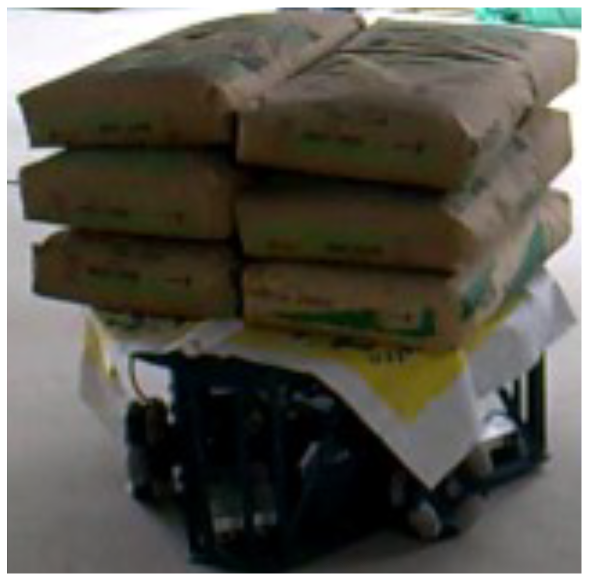
Unlike the automatic mode, this mode has the advantage of having speed regulation, i.e., when the user needs torque, the speed could be reduced by means of the potentiometer located on the control device, thus achieving a higher load capacity as shown in
Figure 39.
Table 6 below shows the following test results.
In teleoperated mode, the platform successfully transports a load of up to 300 kgf. Given the platform’s approximate self-weight of 100 kgf, the resulting payload-to-weight ratio is
This result demonstrates that under manual control, the platform is capable of handling a load three times its own weight. The ability to adapt in real-time to trajectory dynamics and load variations during teleoperation allows for optimal utilization of the available motor torque and structural capabilities, overcoming the limitations observed in the fully autonomous mode.
6.2.3. Analysis of Limiting Factors in Automatic Mode
As described in
Section 6.1, curvilinear (linear and circular) trajectories are generated from predefined motion commands characterized by three parameters: final position, velocity, and acceleration. These parameters are used to calculate the required angular velocities (in steps) for each motor through the inverse kinematics model. However, the definition of these parameters is carried out manually and intuitively, without prior dynamic or kinematic validation.
This approach, although valid for exploratory purposes, leads to the following potential issues:
The generation of step commands that are physically unfeasible under real load conditions.
The exceedance of motor torque limits during certain phases of the trajectory.
The loss of motor synchronization (step loss), especially during curves with abrupt tangential acceleration changes.
As a result of these inaccuracies, the platform is reliably able to transport up to 150 kgf in automatic mode. However, when the load exceeds 150 kgf, the motors are unable to execute the planned movements, as the computed steps from the inverse kinematics demand more torque than available.
Conversely, in teleoperated mode, the human operator continuously adjusts the movement parameters in real-time, intuitively compensating for variations in load and trajectory dynamics. This capability enables the stable transportation of loads up to 300 kgf without the need for predefined kinematic profiles.
Based on these findings, the following improvement lines are proposed for future developments:
Implementation of a dynamic trajectory planner capable of automatically optimizing velocity and acceleration parameters according to the load and the desired trajectory;
Integration of a kinematic feasibility validation module to detect commands that may saturate motor torque or speed limits before execution;
Enhancement of the control system through closed-loop feedback using position and torque sensors, enabling adaptive responses to dynamic changes during operation.
7. Discussion and Conclusions
In the mathematical model, the center of gravity of the load was considered to be coincident with the center of the platform, which in reality is not so, causing the motors to try to exert a torque greater than those calculated by the simulation. To avoid including this condition in the calculation, the reduction was increased.
The experiments performed with the kinematic and dynamic model allowed to evaluate the performance of the three-wheeled omnidirectional mobile robot. It was determined that the motors reach a speed of 300 rpm and a torque of 9 Nm. With the 4:1 reduction provided by the belt system, the wheels achieved a maximum speed of 75 rpm and a torque of 36 Nm.
In terms of load capacity, the prototype can move up to 150 kgf in automatic mode and 300 kgf in teleoperated mode. However, higher loads such as 300 kgf would be desirable, suggesting the need to replace the belt drive with a worm and pinion system. The use of a pinion and worm gear-based transmission system would allow a reduction ratio of 20:1 to be achieved, which would increase torque to 180 Nm. Nonetheless, this modification would reduce the wheel speed to 15 rpm, so it would be necessary to evaluate its impact on the overall performance of the robot platform.
In addition, it has been identified that the rated torque of the motor is directly related to the weight of the platform. In turn, the weight of the platform depends on its size, which is conditioned by the dimensions of the internal elements. Therefore, it is essential to establish a balance between these variables in order to optimize the system design.
The current material of the rollers is Duralon, which is made of fiberglass and epoxy resin. This provides high mechanical strength, good damping capacity (elasticity), and water repellency, avoiding moisture absorption.
Finally, as future work, the following is recommended:
Currently, the robot platform is powered by a power cable. A lithium battery system, accompanied by an adequate calculation of its capacity in ampere-hours to ensure optimal autonomy, would be beneficial for the system. In this case, it would be essential to design an efficient charging and discharging circuit to protect the batteries and optimize their performance. With this improvement, an autonomous platform will be achieved, increasing its mobility and versatility in different applications.
Location sensors such as GPS and/or distance sensors can be used to detect and achieve obstacle avoidance.
The microcontroller can be replaced by a computer or a more powerful processor, as the algorithms are currently implemented and run on an external computer.
Author Contributions
Conceptualization, J.J.Y.-F., J.G.V., E.D.O., C.B. and A.J.; methodology, J.J.Y.-F. and J.G.V.; software, J.J.Y.-F.; validation, J.J.Y.-F. and J.G.V.; formal analysis, J.J.Y.-F.; investigation, J.J.Y.-F. and J.G.V.; resources, J.J.Y.-F. and J.G.V.; data curation, J.J.Y.-F. and J.G.V.; writing—original draft preparation, J.J.Y.-F.; writing—review and editing, J.G.V.; visualization, J.J.Y.-F.; supervision, J.G.V., E.D.O., C.B. and A.J.; project administration, J.G.V. and C.B.; funding acquisition, J.G.V., E.D.O. and C.B. All authors have read and agreed to the published version of the manuscript.
Funding
The research leading to this result received funding from projects “iRoboCity2030-CM, Robótica inteligente para ciudades sostenibles” (TEC-2024/TEC-62) and “FotoArt5.0-CM, Laboratorios inteligentes para la ciencia del futuro”, (TEC-2024/TEC-308) funded by “Programas de Actividades I+D en Tecnologías de la Comunidad de Madrid”.
Institutional Review Board Statement
Not applicable.
Informed Consent Statement
Not applicable.
Data Availability Statement
No new data were created or analyzed in this study. Data sharing is not applicable to this article.
Acknowledgments
The authors would like to thank Carlos Balaguer Bernaldo de Quirós for his support during the research.
Conflicts of Interest
The authors declare no conflicts of interest.
Abbreviations
The following abbreviations are used in this manuscript:
| FEM | Finite Element Method |
| CP | Continuous Path Control |
| PTP | Pose-to-Pose Control |
References
- Azizi, M.R.; Rastegarpanah, A.; Stolkin, R. Motion Planning and Control of an Omnidirectional Mobile Robot in Dynamic Environments. Robotics 2021, 10, 48. [Google Scholar] [CrossRef]
- Li, H.; Liu, J.; Lyu, C.; Liu, D.; Liu, Y. Design and Implementation of Omnidirectional Mobile Robot for Materials Handling among Multiple Workstations in Manufacturing Factories. Electronics 2023, 12, 4693. [Google Scholar] [CrossRef]
- Rubies, E.; Palacín, J.; Bitriá, R.; Clotet, E. Estimation of Motion Capabilities of Mobile Platforms with Three Omni Wheels Based on Discrete Bidirectionality Compliance Analysis. Appl. Sci. 2024, 14, 7160. [Google Scholar] [CrossRef]
- Mohamed, S.; Vellaiyan, V.; Kim, K.; Kim, Y.; Shin, B. Development of a Four Omni-Wheeled Mobile Robot Using Telescopic Legs. Machines 2025, 13, 292. [Google Scholar] [CrossRef]
- Fraifer, M.A.; Coleman, J.; Maguire, J.; Trslić, P.; Dooly, G.; Toal, D. Autonomous Forklifts: State of the Art—Exploring Perception, Scanning Technologies and Functional Systems—A Comprehensive Review. Electronics 2025, 14, 153. [Google Scholar] [CrossRef]
- Akkad, H.; Almusawi, H. A Comparative Review of Omnidirectional Wheel Types for Mobile Robotics. Preprint 2023. [Google Scholar] [CrossRef]
- Hijikata, M.; Miyagusuku, R.; Ozaki, K. Omni Wheel Arrangement Evaluation Method Using Velocity Moments. Appl. Sci. 2023, 13, 1584. [Google Scholar] [CrossRef]
- Manzl, P.; Sereinig, M.; Gerstmayr, J. A Mecanum wheel model based on orthotropic friction with experimental validation. Mech. Mach. Theory 2024, 193, 105548. [Google Scholar] [CrossRef]
- Yadav, P.S.; Mohanta, J.C.; Agrawal, V.; Ahmed, M.F. Modeling and performance evaluation of mecanum wheel platform with reduced vibration and a robust path planning. J. Braz. Soc. Mech. Sci. Eng. 2024, 46, 292. [Google Scholar] [CrossRef]
- Palacín, J.; Rubies, E.; Clotet, E.; Martínez, D. Evaluation of the Path-Tracking Accuracy of a Three-Wheeled Omnidirectional Mobile Robot Designed as a Personal Assistant. Sensors 2021, 21, 7216. [Google Scholar] [CrossRef]
- Tagliavini, L.; Colucci, G.; Botta, A.; Cavallone, P.; Baglieri, L.; Quaglia, G. Wheeled Mobile Robots: State of the Art Overview and Kinematic Comparison Among Three Omnidirectional Locomotion Strategies. J. Intell. Robot. Syst. 2022, 106, 57. [Google Scholar] [CrossRef] [PubMed]
- Robotics, C. Ridgeback Indoor Robot Platform, 2024. Available online: https://clearpathrobotics.com/ridgeback-indoor-robot-platform (accessed on 25 May 2024).
- Robot, F. Omni Wheel Robot Platform A012, 2024. Available online: https://www.fdatabot.com/robots/omnidirectional-wheel-robotics-platform/ (accessed on 25 May 2024).
- RoboCT. CTP300-7 Autonomous Mobile Platform, 2024. Available online: https://www.tegakari.net/en/2023/11/roboct_autonomous-mobile-platform/ (accessed on 25 May 2024).
- BeeWaTec. Mobile Robots Wheel.Me Genius 2, 2024. Available online: https://www.beewatec.com/en/mobile-robots-wheel-me (accessed on 25 May 2024).
- Aethon. T3 Autonomous Mobile Robot, 2024. Available online: https://aethon.com/t3/ (accessed on 25 May 2024).
- Robot, N. 3WD 48mm Omni Wheel Robot Platform, 2024. Available online: https://www.nexusrobot.com/product/3wd-48mm-omni-wheel-robot-platform-chassiswith-encoderblack-15001b.html (accessed on 25 May 2024).
- He, C.; Wu, D.; Chen, K.; Liu, F.; Fan, N. Analysis of the Mecanum wheel arrangement of an omnidirectional vehicle. Proc. Inst. Mech. Eng. Part C J. Mech. Eng. Sci. 2019, 233, 5329–5340. [Google Scholar] [CrossRef]
- Fiedeń, M.; Bałchanowski, J. A Mobile Robot with Omnidirectional Tracks—Design and Experimental Research. Appl. Sci. 2021, 11, 11778. [Google Scholar] [CrossRef]
- Park, Y.K.; Lee, P.; Choi, J.K.; Byun, K.S. Analysis of factors related to vertical vibration of continuous alternate wheels for omnidirectional mobile robots. Intell. Serv. Robot. 2016, 9, 207–216. [Google Scholar] [CrossRef]
- Wang, C.; Liu, X.; Yang, X.; Hu, F.; Jiang, A.; Yang, C. Trajectory Tracking of an Omni-Directional Wheeled Mobile Robot Using a Model Predictive Control Strategy. Appl. Sci. 2018, 8, 231. [Google Scholar] [CrossRef]
- Simerean, A.C.; Tătar, M.O. Contributions to the Development of Tetrahedral Mobile Robots with Omnidirectional Locomotion Units. Machines 2024, 12, 852. [Google Scholar] [CrossRef]
- International Organization for Standardization. ISO 8373:2021—Robotics—Vocabulary, 3rd ed.; ISO: Geneva, Switzerland, 2021. [Google Scholar]
- Muñoz Martínez, V.F.; Gil-Gómez, G.; García Cerezo, A. Modelado cinemático y dinámico de un robot móvil omni-direccional. In Proceedings of the XXIV Jornadas de Automática, León, España, 10–12 September 2003. [Google Scholar]
- Yunardi, R.T.; Arifianto, D.; Bachtiar, F.; Prananingrum, J.I. Holonomic Implementation of Three Wheels Omnidirectional Mobile Robot using DC Motors. J. Robot. Control (JRC) 2021, 2, 65–71. [Google Scholar] [CrossRef]
- Ye, C.; Zhang, J.; Yu, S.; Ding, G. Movement Performance Analysis of Mecanum Wheeled Omnidirectional Mobile Robot. In Proceedings of the 2019 IEEE International Conference on Mechatronics and Automation (ICMA), Tianjin, China, 4–7 August 2019; pp. 1453–1458. [Google Scholar] [CrossRef]
- Budynas, R.G.; Nisbett, J.K. Elementos mecánicos flexibles. In Diseño en Ingeniería Mecánica de Shigley; McGraw-Hill Interamericana: Mexico City, Mexico, 2008; Chapter 17; pp. 860–874. [Google Scholar]
- Liang, L.; Liu, H.; Li, X.; Zhu, X.; Lan, B.; Liu, Y.; Wang, X. Model-Based Coordinated Trajectory Tracking Control of Skid-Steer Mobile Robot with Timing-Belt Servo System. Electronics 2023, 12, 699. [Google Scholar] [CrossRef]
- Zhao, A.; Toudeshki, A.; Ehsani, R.; Sun, J.Q. Data-Driven Inverse Kinematics Approximation of a Delta Robot with Stepper Motors. Robotics 2023, 12, 135. [Google Scholar] [CrossRef]
- Rojas Moya, G. Diseño Estructural de Acero: Armaduras de Acero. Instituto Tecnológico de Costa Rica, Escuela de Ingeniería en Construcción. Available online: https://www.academia.edu/17411121/Armaduras_de_acero (accessed on 6 June 2024).
- Zhao, S.; Hwang, S.H. ROS-Based Autonomous Navigation Robot Platform with Stepping Motor. Sensors 2023, 23, 3648. [Google Scholar] [CrossRef]
- Wantai. NEMA 34 85BYGH450D-008 Stepper Motor. Step Motor Hybrid with High Torque Suitable for CNC and Engraving Machines. 2014. Available online: https://www.wantmotor.com/hybrid-stepper-motor/2-phases-hybrid-stepper-motor/85bygh-stepper-motor.html (accessed on 25 November 2024).
- Darie, E.; Pécsi, R.; Culcea, M. Speed Control of the Direct Current Servomotor and the Stepper Motor with Arduino UNO Platform. IOP Conf. Ser. Earth Environ. Sci. 2021, 664, 012055. [Google Scholar] [CrossRef]
- Wantai. DQ860MA Hybrid Stepper Motor Driver. Datasheet for Hybrid Stepper Motor Driver, Designed for Driving Two-Phase Stepper Motors with High Performance. 2014. Available online: https://www.wantmotor.com/hybrid-stepper-motor-driver/2-phases-hybrid-stepper-motor-driver/dq860ma-hybrid-stepper-motor-driver.html (accessed on 25 November 2024).
- Arduino, S.r.l. Arduino® Mega 2560 Rev3 Product Reference Manual; Arduino S.r.l.: Monza, Italy, 2024. [Google Scholar]
Figure 2.
The structure of the omniwheel [
21].
Figure 2.
The structure of the omniwheel [
21].
Figure 3.
Omnidirectional robot CAD design.
Figure 3.
Omnidirectional robot CAD design.
Figure 4.
Universal/omniwheels, assembly of two wheels with rollers distributed at 90° intervals, with a 45° angular offset between the wheels.
Figure 4.
Universal/omniwheels, assembly of two wheels with rollers distributed at 90° intervals, with a 45° angular offset between the wheels.
Figure 5.
Omnidirectional robot platform movement directions.
Figure 5.
Omnidirectional robot platform movement directions.
Figure 6.
Kinematic diagram of the omnidirectional robot platform.
Figure 6.
Kinematic diagram of the omnidirectional robot platform.
Figure 7.
Reference system: robot vs. wheel.
Figure 7.
Reference system: robot vs. wheel.
Figure 8.
Wheel in contact with the ground.
Figure 8.
Wheel in contact with the ground.
Figure 9.
Omnidirectional wheel reference system.
Figure 9.
Omnidirectional wheel reference system.
Figure 10.
Rotational motion reference system.
Figure 10.
Rotational motion reference system.
Figure 13.
Omnidirectional wheel geometry.
Figure 13.
Omnidirectional wheel geometry.
Figure 14.
Roller shaft—von Mises stress.
Figure 14.
Roller shaft—von Mises stress.
Figure 15.
Dimensions of the ellipsoid.
Figure 15.
Dimensions of the ellipsoid.
Figure 16.
Graph of stress and shear evolution.
Figure 16.
Graph of stress and shear evolution.
Figure 17.
Safety factor of the base plate.
Figure 17.
Safety factor of the base plate.
Figure 18.
Distribution of the transmission system and electronic components.
Figure 18.
Distribution of the transmission system and electronic components.
Figure 19.
Types of roof trusses [
30].
Figure 19.
Types of roof trusses [
30].
Figure 20.
Upper frame of the platform.
Figure 20.
Upper frame of the platform.
Figure 21.
Free body diagram of the omnidirectional platform.
Figure 21.
Free body diagram of the omnidirectional platform.
Figure 22.
The von Mises equivalent stresses of the platform.
Figure 22.
The von Mises equivalent stresses of the platform.
Figure 23.
Total platform deformation.
Figure 23.
Total platform deformation.
Figure 24.
Platform safety factor regarding stress.
Figure 24.
Platform safety factor regarding stress.
Figure 27.
Placement of the developed of electronic and electrical system components.
Figure 27.
Placement of the developed of electronic and electrical system components.
Figure 28.
Stepper motor coil identification [
32].
Figure 28.
Stepper motor coil identification [
32].
Figure 29.
Stepper motor controller.
Figure 29.
Stepper motor controller.
Figure 30.
Arduino Mega 2560 Rev3 [
35].
Figure 30.
Arduino Mega 2560 Rev3 [
35].
Figure 31.
Components X(t) and Y(t) of the trajectory.
Figure 31.
Components X(t) and Y(t) of the trajectory.
Figure 32.
Components of the trajectory .
Figure 32.
Components of the trajectory .
Figure 33.
Components of the trajectory .
Figure 33.
Components of the trajectory .
Figure 34.
Robot platform path.
Figure 34.
Robot platform path.
Figure 35.
Angular speed of each wheel.
Figure 35.
Angular speed of each wheel.
Figure 36.
Torque of each wheel.
Figure 36.
Torque of each wheel.
Figure 37.
Power of each wheel.
Figure 37.
Power of each wheel.
Figure 38.
Robot platform with 150 kgf load.
Figure 38.
Robot platform with 150 kgf load.
Figure 39.
Robot platform with 300 kgf load.
Figure 39.
Robot platform with 300 kgf load.
Table 1.
Commercial omnidirectional mobile platforms for material handling.
Table 1.
Commercial omnidirectional mobile platforms for material handling.
| Platform | Configuration | Dimensions (mm) | Payload (kg) | Weight (kg) | Payload Fraction |
|---|
| Ridgeback (Clearpath Robotics) [12] | 4 wheels | 960 × 793 × 311 | 100 | 135 | 0.74 |
| A012 Omni (Fdata Robot) [13] | 4 wheels | 620 × 520 × 340 | 60 | 44 | 1.36 |
| CTP300-7 (RoboCT) [14] | 4 wheels | 815 × 613 × 330 | 300 | 57 | 5.26 |
| Genius 2 (BeeWaTec) [15] | 4 wheels | 495 × 700 | 250 | 18.4 | 13.6 |
| T3 (Aethon) [16] | 4 wheels | N/A | 340 | 136 | 2.5 |
| 3WD 48mm (Nexus Robot) [17] | 3 wheels | 231 × 203 × 99 | 1.5 | 1.5 | 1.0 |
Table 2.
Kinematic configuration parameters.
Table 2.
Kinematic configuration parameters.
| | Wheel 1 | Wheel 2 | Wheel 3 |
|---|
| | | |
Table 3.
Properties of transmission components.
Table 3.
Properties of transmission components.
| Component | Parameter | Value |
|---|
| Belt | Designation | PHG 160-XL-037 |
| | Belt width (mm) | 9.525 |
| | Current service factor | 0.55 |
| | Belt power (kW) | 0.02 |
| | Belt mass (kgf) | 0.01 |
| Driver Pulley | Designation | PHP 14-XL-37 RSB |
| | Reference diameter (mm) | 22.64 |
| | Number of teeth | 14 |
| | Pitch (in) | 0.2 |
| Driven Pulley | Designation | PHP 56-XL-37.5 RTB |
| | Reference diameter (mm) | 90.55 |
| | Number of teeth | 56 |
| | Pitch (in) | 0.2 |
Table 4.
Comparison between stepper motors and servomotors.
Table 4.
Comparison between stepper motors and servomotors.
| Stepper Motor | Servomotors |
|---|
| No feedback required (open loop control). | Feedback (potentiometer, encoders, etc.) is essential. |
| Poor power-to-volume ratio, which is why they are larger. | Better power-to-volume ratio. |
| Robust, they age very slowly. | They show brush aging (if brushed motor). |
| Good blocking characteristics. | Extra brakes (mechanical devices) typically required for blocking. |
| Prone to resonance—noise. | Smooth movement. |
| No ventilation system, prone to overheating. | The ventilation system may be easily contaminated. |
| Low cost and widely available. | Higher cost and specialized availability. |
Table 5.
Load test with 150 kgf.
Table 5.
Load test with 150 kgf.
| Parameter | Value |
|---|
| Load | 150 kgf |
| Divergence in Y | 2 cm |
| Divergence in X | 2.5 cm |
| Operating time | 125 s |
| Observations | None |
Table 6.
Load performance and speed regulation.
Table 6.
Load performance and speed regulation.
| Load [kgf] | Speed Regulation [%] | Observation |
|---|
| 100 | 80 | Pass |
| 200 | 60 | Pass |
| 300 | 20 | Pass |
| 350 | — | Cannot move |
| Disclaimer/Publisher’s Note: The statements, opinions and data contained in all publications are solely those of the individual author(s) and contributor(s) and not of MDPI and/or the editor(s). MDPI and/or the editor(s) disclaim responsibility for any injury to people or property resulting from any ideas, methods, instructions or products referred to in the content. |
© 2025 by the authors. Licensee MDPI, Basel, Switzerland. This article is an open access article distributed under the terms and conditions of the Creative Commons Attribution (CC BY) license (https://creativecommons.org/licenses/by/4.0/).


 ,
, 


