Article

Study on Influence of Grouting on Mechanical Characteristics and Stress Concentration in Hole-Containing Rock

1
Key Laboratory of Intelligent Health Perception and Ecological Restoration of Rivers and Lakes, Ministry of Education, Hubei University of Technology, Wuhan 430068, China
2
China State Key Laboratory of Geomechanics and Geotechnical Engineering, Institute of Rock and Soil Mechanics, Chinese Academy of Sciences, Wuhan 430071, China
*
Author to whom correspondence should be addressed.
Appl. Sci. 2025, 15(10), 5245; https://doi.org/10.3390/app15105245
Submission received: 22 February 2025 / Revised: 28 April 2025 / Accepted: 2 May 2025 / Published: 8 May 2025

Abstract

:
Grouting technology is a pivotal methodology for enhancing the mechanical properties of defective surrounding rock masses in tunnel engineering. Through uniaxial compression tests on intact, hole-containing, and grouted marble specimens, the influence of cement grout filling on the mechanical behavior of marble containing holes was investigated. Based on the experimental results, discrete element method (DEM) models were established for the three types of specimens, revealing the mesoscopic crack propagation mechanisms and stress distribution in potential stress concentration zones during failure. The experimental results demonstrated that the implementation of cement grouting enhanced the strength properties of the specimens by 22.38%. In terms of failure modes, the failure mode of the grouted specimens was similar to that of the intact specimens, and the filling material transformed the failure mode from tensile to shear failure. Numerical simulations revealed differences in microcrack evolution: cracks in the hole-containing specimens initiated near the upper and lower ends of the holes, while cracks in the grouted specimens originated around the filling material, with both types propagating axially. Microcracks in the grouted specimens initiated earlier, but the majority of microcracks in both types developed after peak stress and were predominantly tensile. The stress concentration coefficients for the intact, grouted, and hole-containing specimens were approximately 0.84, 2.25, and 2.96, respectively. The grouted specimens shortened the duration and alleviated the degree of stress concentration in the defect zones. This study elucidates the grouting reinforcement mechanisms in defective tunnel surrounding rock through a multiscale approach, providing theoretical underpinnings for optimizing tunnel support systems and preventing engineering hazards including collapse and rockburst.

1. Introduction

In tunnel engineering, the presence of natural cavities within surrounding rock masses and excavation-induced fractures pose significant threats to structural stability, frequently triggering localized collapses. Grout infusion technology, which mitigates structural instability by filling defect zones and optimizing stress distribution in rock media, has evolved as an integral component of modern tunnel support systems. While empirical studies have demonstrated that the synergistic interaction between cementitious grouts and void-containing rock matrices markedly enhances bearing capacity, the micro-mechanical mechanisms governing interfacial bonding and stress redistribution patterns remain insufficiently elucidated. The study of the failure behavior of defect-containing rock masses and the mechanical properties and reinforcement mechanisms of grouted rock masses is of significant theoretical and engineering value for ensuring the long-term stability and safety of underground engineering structures.
In a previous study on defective rocks, Lajtai et al. [1] investigated the generation and extension of microcracks during compression and their effect on material damage by prefabricating fissures of different lengths and inclination angles. The study found that elastic cracks produce two types of fracture: one that begins at the maximum stretch at the crack boundary and one that begins at the compressive stress concentration at the crack boundary. Carter et al. [2] conducted a study on the fracture process of rocks containing a single circular hole. It was determined that the cracking observed in the vicinity of circular apertures, occurring under conditions of low peripheral pressure, predominantly comprises primary tensile cracks, secondary cracks, and shear cracks. Wong et al. [3] utilized high-speed photography to meticulously observe the development of cracks and identified seven distinct types of cracks based on their geometry and propagation mechanisms. This seminal study addressed the ambiguity and lack of clarity in the literature regarding crack terminology and classification. In recent years, scholars have carried out a large number of studies on defective rocks. Yang et al. [4] conducted indoor tests and numerical simulations on brittle rocks containing pore defects and found that crack initiation and extension always start from the tensile stress concentration area of the pore. Yang et al. [5] conducted uniaxial compression tests on brittle sandstone specimens containing a single cleavage and found that the fracture evolution process of cleavage-bearing rocks under uniaxial compression conditions produces wing cracks and secondary cracks. Janeiro et al. [6] investigated the variation in the strength and deformation properties of rock-like materials with the geometry of their internal holes by prefabricating circular and square holes in gypsum samples but did not consider other geometries. Zhao et al. [7] and Li et al. [8] conducted uniaxial compression tests and simulation tests, respectively, on rocks containing holes of different shapes. The conclusion drawn was that the shape of the holes affects the compressive strength and modulus of elasticity of rocks. In the study by Liu et al. [9], the impact of hole shape on the mechanical properties and failure modes of laminated rocks was investigated through FDEM simulations. The findings indicated that square and circular holes exhibited the least detrimental effect on the compressive strength of the material. Li et al. [10] utilized a high-speed camera to record the initiation, expansion, and penetration of cracks surrounding the holes. This study further revealed that holes with different boundary types exhibit distinct crack expansion characteristics. Zhang et al. [11] simulated the single triaxial compression test on rocks containing double circular holes by PFC and found that the cracks in the compressive stress concentration area extended and experienced damaged in the direction of the maximum principal stress. Subsequently, Zhou et al. [12] revealed that the direction of initial tensile crack sprouting in rocks containing double circular holes is independent of the bridge angle by PFC and only affects the strength of the specimen and the damage morphology. In the study conducted by Zhang et al. [13], uniaxial compression tests were performed on marble specimens with varying number of holes and pore diameter. The results obtained revealed a gradual decrease in the modulus of elasticity, peak strength, and cracking stress of the specimens with an increase in the number of holes and pore diameter. Jespersen et al. [14,15] reported that in addition to the number of holes, the distribution characteristics of porous holes also have a significant effect on the compressive strength and damage pattern of rock, mainly depending on the angle and spacing of the rock bridge. Zhu et al. [16] investigated the effect of the elliptical length–short axis ratio and inclination angle on the mechanical properties of marble. This investigation was conducted through the uniaxial compression of slab marble specimens containing prefabricated elliptical holes. Zhu et al. [17] conducted uniaxial compression tests on sandstones with combined defects of prefabricated circular holes and fissures and found that the peak strength and average modulus of the specimens decreased gradually with the increase in the fissure inclination.
The process of grouting reinforcement involves the repair of physical holes in the rock, the alteration of the state of stress in the rock, and the provision of new material characteristics to the rock. In the study by Tang Jianxin et al. [18], uniaxial compression tests were conducted on fractured rocks following the implementation of grouting techniques. The findings revealed a substantial enhancement in the peak strength, modulus of elasticity, and peak strain of the rocks post-grouting. Building upon these observations, Zhang et al. [19] conducted triaxial compression tests, which indicated that peak strength and strain exhibited a positive correlation with the increase in peripheral pressure. Wang et al. [20] revealed the damage mechanism of the crack test after grouting reinforcement. The results of the study indicated that the cracks exhibited a tendency to sprout from the same location in the specimen before and after grouting. Furthermore, the damage morphology was found to be more similar to that of the intact specimen following grouting. Shen et al. [21] found that the grouted body can transform the specimen from the typical elastic–brittle type of the original rock to the type of elastic to some range of plastic to brittle or the ideal elastic–plastic type. Zuo et al. [22] conducted uniaxial compression and acoustic emission tests on gypsum-filled marble containing holes and analyzed the crack extension law. The results of this analysis demonstrated that the presence of gypsum filler within the marble matrix was able to inhibit the development of cracks. Zhou et al. [23] conducted uniaxial compression and acoustic emission tests on rocks with elliptical holes. These tests were performed by filling the holes with cement mortar at varying ratios. The results of the study indicated that the failure mode shifted from tensile to shear damage. This shift occurred in conjunction with an enhancement in the mechanical properties of the filler. Zhang et al. [24] conducted a series of indoor and simulation tests on unfilled and fully grouted specimens. The findings of the research study demonstrated that the grouted body served to mitigate the stress concentration phenomenon. Lu et al. [25] established that in instances of damage to grouted specimens, a substantial number of cracks emerged along the apertures where conical damage was observed. These cracks underwent a process of downward extension and expansion, ultimately leading to penetration. In the study conducted by Liu et al. [26], uniaxial compression tests were performed on fractured rock bodies utilizing various grouting materials. The findings of the research study indicated that epoxy filling exhibited the most significant impact on enhancing the strength of the fractured rock bodies.
Despite significant advancements in existing research, grouting reinforcement in tunnel engineering still grapples with two persistent challenges: (1) The mechanical behavior of grout–rock interfaces under complex geological conditions remains inadequately characterized, hindering the accurate prediction of multiscale failure mechanisms in reinforced surrounding rock masses. (2) While current studies predominantly focus on mesoscopic parameters, insufficient attention has been devoted to the systematic analysis of microcrack propagation in cavity zones and dynamic responses of stress fields during grout consolidation. In conclusion, it is necessary to conduct a comprehensive study on the mechanical properties, fracture process, and development of microcracks of rocks with grout-filled holes. This would provide a theoretical basis for optimizing the tunnel support system and preventing engineering hazards such as collapse and rockburst. In order to achieve this objective, uniaxial compression tests were initially conducted on intact specimens, hole-containing specimens, and cement mortar-filled specimens. The strength characteristics and failure modes of the three specimens were then analyzed. By utilizing the discrete element method, the mechanical parameters of the material were obtained, thus establishing the numerical model of marble. This study encompasses the strength change rule, the microcrack expansion process, the microcrack number change rule, and the stress change rule around the hole, all under the uniaxial compression condition of the above specimens. With a focus on stress monitoring at the edge of the hole, the mechanical mechanism of the destruction of the grout-filled rock samples was obtained. On the other hand, the problem of stress around the hole was analyzed based on the theory of elastic mechanics.

2. Materials and Testing Methods

2.1. Marble Specimens

The rock specimens used in the test had a density of 2.79 g/cm3 and were taken from the marble specimens of the Jinping Second Hydropower Plant. There are many caves on the site that require special treatment, such as grouting. Geological surveys have determined that circular and quasi-circular shapes are the most common forms of natural karst caves [27]. Howland [28] solved for finite-width plate hole edge stresses by the complex function method and found that the interaction between the hole and the boundary can be disregarded when d > 1.5r. In the formula, d is defined as the distance from the hole to the boundary of the specimen, and r is defined as the radius of the hole. Consequently, circular prefabricated apertures were introduced at the geometric center of the specimen to emulate natural karst caves. The diameter of these apertures was set at 15 mm. The selection and proportioning of grouting materials referred to the study by Zhang et al. [29].
The specimens under consideration were cylinders with dimensions of 50 mm × 100 mm. First, the specimens were subjected to a process of polishing in order to ensure that their surfaces were smooth and met the standards set out in the test method for the physical and mechanical properties of rocks. Subsequently, utilizing conventional C42.5 cement and water in a proportion of 1:0.5 cement slurry, a circular aperture measuring 15 mm in diameter was excavated through the geometric center of the intact rock specimens. The slurry was injected at a uniform rate by using a medical syringe, with light vibration and pressure being used to ensure compaction. The schematic diagrams of the three specimens are shown in Figure 1.

2.2. Test Equipment

As shown in Figure 1b, the test loading system is a multifunctional rock mechanics tester developed by the Wuhan Institute of Geotechnics, Chinese Academy of Sciences. The test system includes a pressure chamber, a high-strength reaction frame, high-pressure electrohydraulic servo system, a microcomputer system, a strain detection and acquisition system, and accessories. Axial stress is controlled by flow loading at a rate of 1 mL/min. There is a high-precision axial differential displacement sensor inside the compression chamber, and the deformation measurement accuracy reaches 0.01 mm. The high-strength reaction frame ensures that the reaction force is uniformly transmitted during the loading process, thus avoiding the error and non-ideal stress distribution caused by the uneven local force, and the load is steadily applied by a high-precision electrohydraulic servo pump. The pressure control accuracy reaches 0.01 MPa, and the servo system can be finely controlled according to the preset deformation speed to achieve the effective control of the entire rock destruction process, ensuring that the specimen can go through the entire compression test process and accurately obtain the complete stress–strain curve.

3. Analysis of Test Results

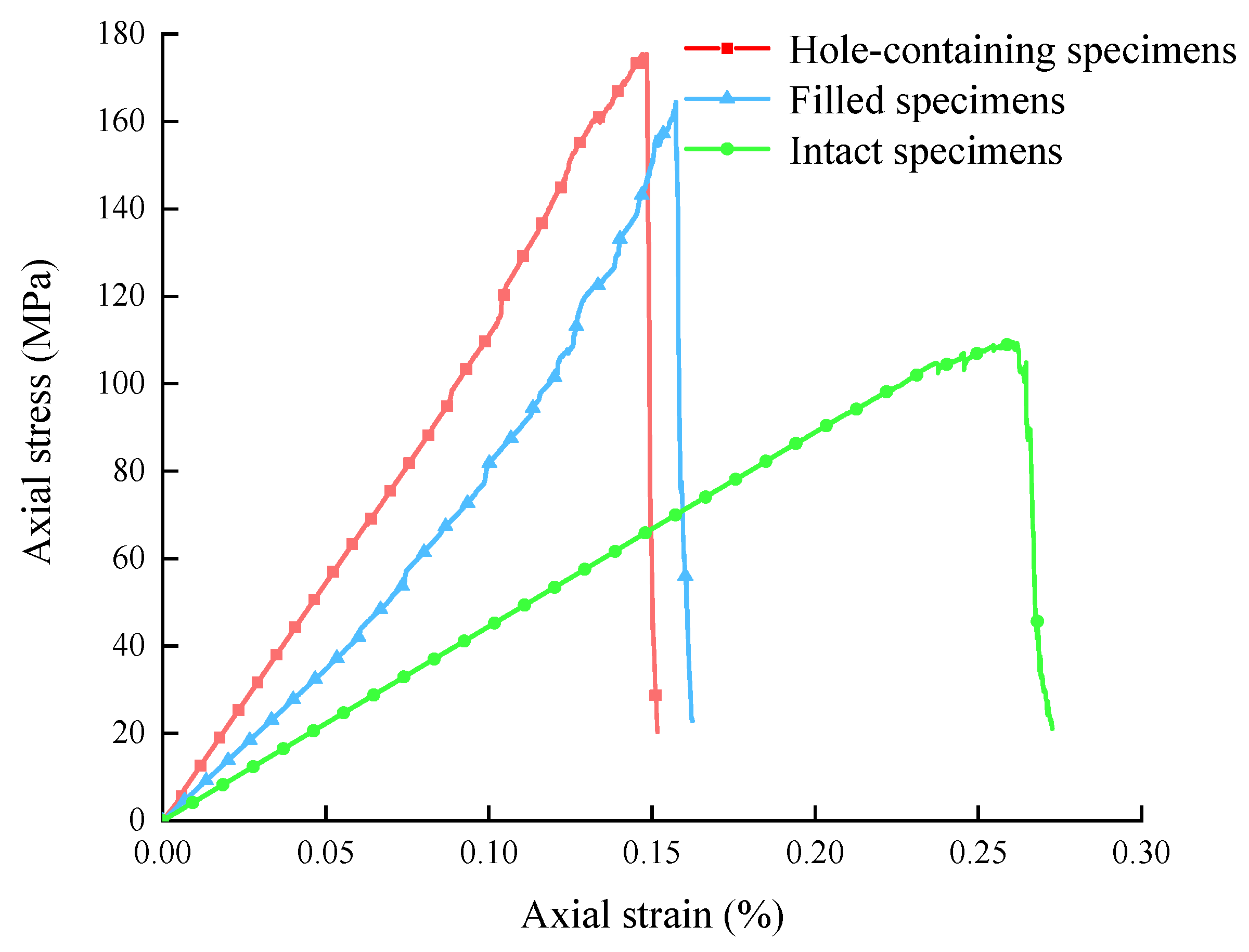
3.1. Stress–Strain Curve

Uniaxial compression tests were conducted on intact, hole-containing, and cement-filled specimens by using a multifunctional rock mechanics tester to investigate the impact of cement slurry filling on the mechanical behavior of marble with holes. The outcomes of these tests on various specimens are presented in Table 1.
The uniaxial compression tests were carried out on intact, hole-containing and cement paste-filled specimens, and the stress–strain curves were obtained as shown in Figure 2. The stress–strain curve of the intact specimens is shown in Figure 2a. The curve shows a small compressive dense phase at the beginning of loading, and with the progressive increase in pressure, the rock specimens enter the linear elastic phase, and the slope of the curve tends to stabilize. The stress–strain curve of the hole-containing specimens is shown in Figure 2b. In comparison with the intact rock specimens, the hole-containing rock specimens reach the peak value when the strain reaches about 0.2%, and the residual strength of the rock specimens falls close to 0 a while after the peak value. Figure 2c shows the stress–strain curve of the cement-filled specimens. The cement filling has an obvious improving effect on the strength of hole-containing rock, because the filling can also bear a part of the pressure, and its peak and residual strengths are improved to different degrees compared with the hole-containing rock specimens.
In summary, the typical intact, unfilled, and cement-filled specimens all pass through five stages, i.e., intact compression, density, linear elasticity, elastic–plastic transition, and plasticity–destruction, in the test, and their peak strengths, peak strains, and elastic moduli decrease sequentially. It is also worth noting that the post-peak residual strength of the intact and cement-filled specimens is around 20 MPa, whereas the residual strength of the hole-containing specimens is close to zero.

3.2. Failure Mode

The final failure modes of the three specimen types are shown in Figure 3. For the intact specimens, the damage pattern shows typical shear damage with shear cracks penetrating to form the damage surface. When the specimen contains hole flaws, stress concentration occurs around the hole, especially in the direction of the principal stress, and typical wing cracks appear in the area of stress concentration of the hole and expand in the direction of the principal stress, eventually showing an inverted “Y”-shaped distribution. For the specimens with cement-filled holes, the presence of the filler makes the stress state around the holes still three-way stress, but with loading and crack development and expansion, the slurry-filled area and the holes are separated, resulting in the slurry being extruded from the holes; the final destruction of the macroscopic cracks is similar to that of the intact rock specimens, for the two macroscopic diagonal shear cracks, and the failure mode is mainly characterized by shear damage.

4. Numerical Simulation

4.1. Numerical Modeling

The diameter of the intact rock samples is 50 mm, the height is 100 mm, the minimum particle size of the rock particles is 0.4 mm, and the ratio of the maximum particle size to the minimum particle size is 1.66, as shown in Figure 4a. These particles are constrained by the four walls to be placed in a box of the same size as the internal test specimen; then, a numerical model of the intact sample can be obtained after the test of the equilibrium of the model. Furthermore, a circular contour with a hole diameter of 15 mm can be imported into the center of the intact sample by the geometry import command; then, the particles in the circular contour can be deleted by the delete command, and finally, the model containing the hole defects can be obtained by rebalancing the process, as shown in Figure 4b. In addition, a region is set at the left tip of the circular hole by using the measure function in PFC (Particle Flow Code), which can monitor the average stress of the marble particles in the region, as shown in Figure 4c.
The micro-mechanical parameters in PFC model materials mainly include the contact between particles, and contact models are mainly linear and include contact bond, parallel bond contact, flat bond, and smooth bond models. As the contact force in the parallel bond contact model exceeds the bond strength, the parallel bond will break, and the bond and the force and moment acting on it will be removed, which is more in line with the mechanical behavior of rock; the parallel bond contact model requires an easier debugging of the microscopic parameters, which is also more widely used [30,31]. Based on this, the numerical models of the three rock samples developed in this paper all adopt the parallel bonded contact model.
The cement-filled specimen model is shown in Figure 5a, where the particle size range of the cement paste is 44 μm to 100 μm, the spatial distribution of the particles is set in a uniform and random manner, and the cement paste particles are distributed in a circular contour based on the hole-containing defect model. The cementation between the cement paste and the rock specimens is critical to the strength of the specimens. Due to the rock-like nature of the cement paste material, the cement paste and rock particles in the filling test model are still modeled with parallel bonding, as shown in Figure 5b. The bond between the grout and the rock is a parallel bond contact force, which is consistent with the overlay type in the bonding pattern at the grout–rock interface described by Li W. et al. [32]. The upper and lower walls of the model are used as loading tools, and the relative movement rate of the upper and lower loading plates is 0.001 mm/s, which simulates the loading rate of 0.002 mm/s used in the indoor tests.

4.2. Model Parameter Calibration

In order to establish a PFC model that can adequately characterize the mechanical properties of actual marble, it is necessary to verify the correctness and adequacy of the model based on the results of indoor tests. We performed a series of “trial and error” procedures [33,34] to determine a set of micro-mechanical parameters that can represent the marble, where the “trial and error method” involved adjusting the micro-mechanical parameters of the PFC model so that the stress–strain curve and the macroscopic damage form of the specimens in the numerical simulation and the indoor test are basically the same. The micro-mechanical parameters are delineated in Table 2.
As demonstrated in Figure 6, the stress–strain curves of the conventional uniaxial compression test of intact marble are compared with the PFC simulation test. The trends of both changes are found to be essentially the same. It is evident that the presence of primary cracks and defects in the interior at the commencement of loading in the indoor test will result in a compression–density phase, consequently leading to a slight depression of the curve at the onset of the indoor test. However, given the rigid nature of the particles in the model and their uniform distribution, the compaction phase of the indoor test cannot be reflected, resulting in a smaller peak strain than the actual value of the indoor test. This discrepancy is attributable to the modeling characteristics of PFC and does not compromise the overall mechanical performance of the material. As illustrated in Table 3, the mechanical parameters of the numerical simulation and indoor test are found to be largely congruent, and the macroscopic morphology of the final failure of the two is found to be largely analogous, thereby indicating that the model is capable of reflecting the macroscopic mechanical properties of marble.

5. Experimental Study with Numerical Methods

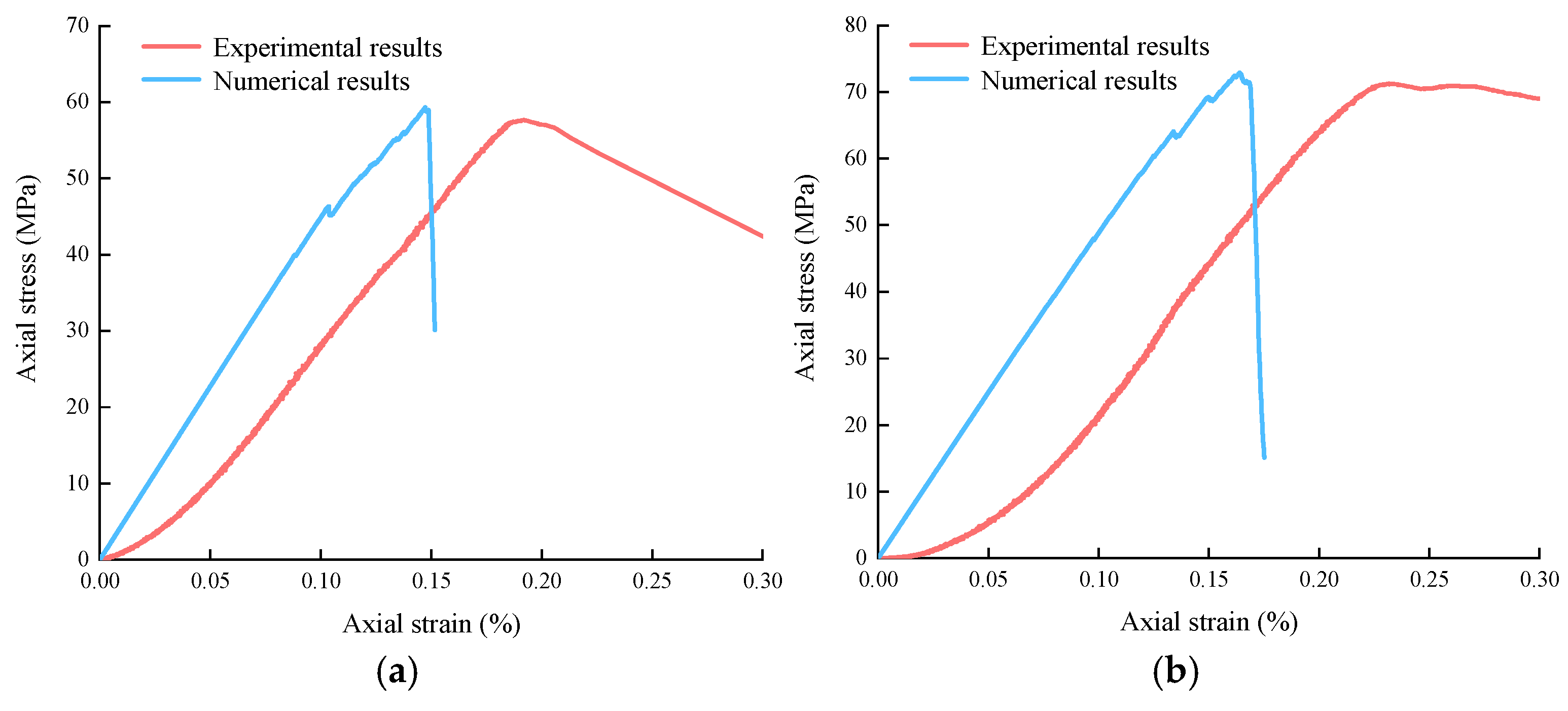
5.1. Adaptation Studies of Models

By utilizing the micro-mechanical parameters enumerated in Table 2, the uniaxial compression process was simulated through the utilization of the defective, cement-filled numerical specimens that were established in the preceding section. The stress–strain curves of the aforementioned numerical models are illustrated in Figure 7, in comparison with the corresponding indoor test specimens. The peak strength and modulus of elasticity of the hole-containing specimens and cement slurry-filled hole specimens were 59.32 MPa and 44.90 GPa, and 72.91 MPa and 48.06 GPa, respectively, and there were significant enhancements in the strength parameters of the cement slurry-filled rock samples, 22.91% and 7.04%, respectively. The average peak strength and average modulus of elasticity of the corresponding specimens in the indoor tests were 60.28 MPa and 41.89 GPa, and 73.78 MPa and 45.04 GPa, with enhancements in strength and modulus of elasticity of 22.40% and 7.52%, respectively. The single strength indexes of numerical and indoor tests demonstrated a high degree of consistency, and the comparison of the transverse indexes of the three types of specimens yielded consistent conclusions. This finding suggests that the micro-mechanical parameters presented in this paper are capable of accurately reflecting the complex morphology and diverse mechanical characteristics of rock–cement paste materials during the loading process.

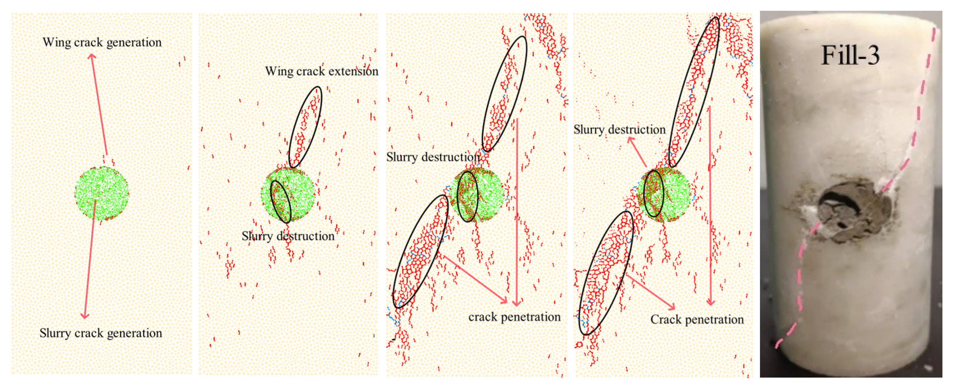
5.2. Failure Pattern

Figure 8 shows the crack development of intact rock specimens, hole-containing rock specimens, and cement-filled hole rock specimens at 70% of peak stress, at peak stress, at 45% after the peak, and in the residual stage. At 70% of peak stress, sporadic microcracks appeared inside the intact specimen. As the experiment continued, tensile microcracks began to increase in number, and shear microcracks appeared on rare occasions. At 45% of peak stress, tensile microcracks increased dramatically, and thorough cracks were formed, resulting in an obvious damage surface. The shear microcracks also began to increase suddenly and mainly appeared in the vicinity of the damage surface. The number of microcracks gradually stabilized and their increment decreased after entering the residual stage.
Two tensile cracks sprouted simultaneously near the top and bottom of the hole center at 70% of peak stress in the hole-containing specimens. This observation aligns with the literature [35,36], which states that sporadic microcracks initially manifest in the stress concentration area. Additionally, a few microcracks emerged in the far field of the hole, exhibiting a predominant tensile crack type. As the axial load increased to reach the peak stress stage, wing-type cracks began to appear on both sides of the hole. In addition, the cracks continued to develop axially, with two distinct tensile cracks appearing above and below the hole, while fewer shear microcracks appeared, which is consistent with the description in the literature [37]. At 45% of peak stress, the tensile microcracks underwent a sharp increase, resulting in the formation of a penetration, which led to the emergence of an obvious rupture surface. At this juncture, the macroscopic cracks formed, and the shear microcracks began to increase, primarily manifesting near the rupture surface. Subsequently to entering the residual stage, a new rupture surface emerged, and the two rupture surfaces, in conjunction with a tensile macrocrack above the hole, collectively formed an inverted “Y”-shaped macrocrack damage surface. This pattern of broken discourse is the same as the results of the literature [38].
Cement-filled specimens initially exhibited sporadic microcracks at the periphery of the apertures and within the cement slurry. As the specimens approached the peak stage, microcracks continued to develop at the primary fracture surface of the rock samples and in the filled slurry. The distribution of cracks was significantly denser than in the first two rock sample types, the hole filling had a higher concentration of cracks compared with intact rock, and wing cracks began to develop in the axial direction. As the specimen progressed to 45% of peak stress, the cracks were essentially complete, and obvious rupture surfaces emerged. This was accompanied by the formation of significant macroscopic cracks, while a substantial number of microcracks manifested within the filling area.
A comparative study of indoor tests and numerical tests was conducted to reproduce the stress–strain pattern, strength characteristics, and macroscopic damage patterns of the intact rock samples, the hole-containing rock samples, and the cement paste-filled rock samples. The numerical analyses demonstrated a high degree of similarity between the models and the actual rock samples. This indicates that the numerical models of the three types of rock samples established in this paper can appropriately reflect the crack extension development path and the microscopic damage mechanism of this rock material in uniaxial compression tests. A comparison of the crack extension process revealed that the cracks in the cement paste-filled rock samples were significantly influenced by the cement paste-filled portion. Their cracks were neither uniformly distributed near the peak as in intact rock nor predominantly distributed as in the wing cracks of hole-containing rock. In the case of the cement slurry-filled rock samples, crack development originated from the periphery of the holes and the internal cracks of the holes. Consequently, the internal microcracks and tangential wing cracks of the holes developed synchronously, and the penetration form of the main cracks was similar to that of the intact rock samples.

5.3. Crack Type and Number Analysis

Figure 9 shows the evolution of the number of tensile and shear microcracks in numerical tests on the intact, hole-containing, and filled specimens. The onset of microcracks within the specimens was observed when the intact test loading was approximately 55% of the peak value, corresponding to a strain of 0.14%. Tensile microcracks exhibited a gradual growth trajectory prior to the peak, subsequently undergoing a substantial escalation post-peak, culminating in a final count of 1411. The onset of shear microcracks was observed to occur prior to the peak, and their growth was found to commence only after the peak. The proportion of microcracks at the time of the peak was found to be 6% of the total microcracks, and the final total number of microcracks was determined to be 1501.
The initial increase in microcracks within the hole-containing specimens remained minimal until a stress level of 67 percent of the peak value was attained, at which point the strain reached 0.07 percent, marking the onset of microcracks. Tensile microcracks exhibited a gradual increase until they reached their peak, with a final count of 753. Shear cracks also increased only slowly until the peak value was reached. Subsequent to this, although the increase became more pronounced, the number of shear microcracks was a mere 7.04% of the total number of cracks, and the ultimate total number of microcracks was 810.
The onset of microcracks within the specimens was observed when the cement-filled specimens were loaded to approximately 55% of the peak value, corresponding to a strain of 0.14%. The number of tensile microcracks increased to 4136 upon reaching the peak. The increase in shear microcracks was relatively gentle, and the final total number of microcracks was 4397, with shear microcracks accounting for 5.94% of this total.
In summary, the prevalence of microcracks in all three specimens was predominantly characterized by tensile microcracks, with shear microcracks exhibiting negligible presence [26]. The cement-filled specimens demonstrated the highest number of total microcracks, followed by the intact specimens, and the specimens containing a hole exhibited the lowest number. The earliest cracking point was observed in the cement paste-filled marble, and the filled area produced a greater number of cracks during the destructive process, which aligns with the performance of the rock specimens in the indoor test.
The relationship between the number of microcracks and axial strain for the hole-containing specimens was fitted to an exponential curve with a strong correlation (R2 = 0.9194), as shown in Figure 10. This high goodness-of-fit indicates that the model reliably captures the progressive development of microcracks during loading. The fitted curve quantitatively characterizes the nonlinear accumulation of microdamage, where the increasing slope reflects the transition from stable crack initiation (Stage I) to unstable crack propagation (Stage II). This aligns with the classic “three-stage” damage evolution theory [39]. This provides a predictive tool for estimating rock failure precursors in engineering applications.

6. Stress Analysis Around the Hole

6.1. Stress Problem of Plane Containing a Hole

As illustrated in Figure 11, the specimen model features a circular aperture with radius R, to which unidirectional pressure q is applied, with an angle θ formed with respect to the vertical direction. In the event of the outer boundary of the model being altered to a circular boundary such that ρ = R 1 (R1 >> R), an inner boundary condition of p = R is established.
In accordance with the particular instance of the planar elliptic model [40] in elastodynamics, that is to say, the situation in which the ratio of the long and short axes is equal to one and the planar hole is circular, the relevant stress expression is as follows:
σ θ = q 2 cos 2 θ 1 + 3 R 4 ρ 4 q 2 1 + R 2 ρ 2 .
Subsequently to the introduction of ρ = R into Equation (1), the resultant stress around the hole is as follows:
σ θ = q 2 cos 2 θ 1
It is, therefore, possible to define the ratio of the maximum shear stress around the hole to the axial principal stress as the stress concentration factor k:
k = σ θ σ c = 2 cos 2 θ 1
The force conditions and boundary conditions of the hole-containing rock specimens in this paper do not fully satisfy the ideal elastic–plastic model; therefore, this paper only draws on the analytical solution of this model as a comparison with the stress monitored at the circle. Subsequently to the introduction of each angle into Equation (3), the resultant table is shown in Table 4. This demonstrates that at an angle of 90°, the maximum compressive stress exists around the hole, with a magnitude of 3q. This indicates that the maximum degree of stress concentration is found on the left and right sides of the hole, and the crack extension presented in Figure 3 and Figure 8 in the test indicates that there is a concentration of stress in this place. As illustrated in Table 1, the average uniaxial compressive strength of the hole-containing rock specimens obtained from the test is 60.29 MPa, indicating that the stress tangential stress on the left and right sides of the hole is approximately 180.87 MPa.

6.2. Stress Monitoring

In accordance with the numerical model, the mechanical behavior of arbitrary rock particles during loading can be directly monitored by employing the FISH language tool. As illustrated in Figure 4c, the pore stress concentration area is designated as the stress detection area at the inception of the modeling process. As demonstrated in Figure 11, the stress–strain curves of the average stress of the marble particles inside the monitoring area of the intact, cement paste-filled, and hole-containing specimens are shown. The monitoring area is capable of producing an output of the stress state in each direction: xx, yy, xy, and yx. However, since the tangential stress σyy is more prominent for the stress concentration phenomenon at the tip [41], this paper only studies the tangential stress σyy at the tip of the hole. The stress concentration factor k is then as follows:
k = σ y y q
The directional stress in the hole monitoring area, denoted by σyy, and the uniaxial compressive strength, denoted by q, are the primary variables of interest.
As demonstrated in Figure 12, the maximum stress value recorded in the monitoring region of the intact specimen is 109.51 MPa, whereas the peak stress achieved in the numerical test is 130.1 MPa. This indicates that the stress concentration phenomenon does not occur in the monitoring region and is not present in the peak region of uniaxial compression damage. The stress concentration factor is approximately 0.84.
The maximum stress value recorded in the monitoring area of the hole-containing specimens is 175.39 MPa, which is a mere 3% of the error value of the analytical solution in Section 5.1 and highly restores the stress concentration state in the direction of the principal stress of the hole rock sample. The peak strength of the rock sample in question is 59.32 MPa, and the stress concentration factor is approximately 2.96, which is consistent with the theoretical solution of the planar elliptic model in elastic–plastic mechanics.
The maximum stress value recorded in the monitoring area of the cement paste-filled specimen is 164.41 MPa, whereas the corresponding peak strength of the rock sample is 72.91 MPa, and the stress concentration factor is approximately 2.3 times the initial value. This finding suggests that the stress concentration persists in the hole edge region of the rock samples following hole filling, albeit at a significantly lower level than that observed in the unfilled rock samples. Under the condition of unfilled holes, there is a critical surface at the hole of the rock samples, which is in a two-way stress state during the stressing process. The presence of cement paste filler results in a transition from a two-way to a three-way force state within the monitoring area. The damage process, as observed in both the indoor test and numerical test, indicates that cement paste detachment from the rock particles occurs in the late stage of the test. Furthermore, stress concentration is evident at this location during the middle and late stages of the test. However, the mechanical properties of the filled rock samples were found to be enhanced to a certain extent by the reduction in the stress concentration time and the weakening of the degree of stress concentration.

7. Conclusions

(1)
In terms of strength, the mean uniaxial compressive strength of cement paste-filled specimens increased by 22.38% compared with the unfilled specimens but remained significantly lower than that of the intact specimens. The residual strengths of the intact and cement paste-filled samples were nearly equal, while the residual strength of the hole-containing samples was almost negligible.
(2)
Regarding the failure mode, specimen damage primarily originated from the stress concentration area, which promoted crack extension and penetration, ultimately leading to failure. The final macroscopic cracks exhibited an inverted “Y” distribution. The failure mode of the cement paste-filled specimens closely resembled that of the intact specimens, transitioning from tensile to shear damage.
(3)
In the numerical simulation, microcracking in the hole-containing specimens initiated near the top and bottom ends of the circular hole. In contrast, the microcracks in the cement slurry-filled specimens first emerged around the filler. These microcracks then propagated axially towards both ends. Microcracking initiated at approximately 67% of peak stress in the hole-containing specimens, compared with 33% in the cement paste-filled specimens. The vast majority of microcracks in both specimens appeared after the peak strength was reached, and both were dominated by tensile microcracks.
(4)
Regarding stress concentration, the average stress levels in the designated monitoring area decreased sequentially for the hole-containing, cement slurry-filled, and intact specimens. The stress concentration factor decreased from 2.96 to 2.3 after filling. The cement paste filling shortened stress concentration duration, reduced its intensity, and enhanced material strength.

Author Contributions

Conceptualization, Y.Y.; methodology, Z.K. and S.Q.; software, Z.K. and J.P.; validation, Y.Y. and L.Y.; formal analysis, Y.Y.; investigation, S.Q.; resources, Y.Y.; data curation, Z.K.; writing—original draft, Z.K.; writing—review & editing, Y.Y.; project administration, Y.Y.; funding acquisition, Y.Y. All authors have read and agreed to the published version of the manuscript.

Funding

This research study was funded by the Natural Science Foundation of China (42377172).

Institutional Review Board Statement

Not applicable.

Informed Consent Statement

Not applicable.

Data Availability Statement

The original contributions presented in this study are included in the article. Further inquiries can be directed to the corresponding author.

Acknowledgments

The authors want to thank the editor and anonymous reviewers for their valuable suggestions for improving this paper.

Conflicts of Interest

The authors declare no conflicts of interest.

Abbreviations

RHole radius
qUnidirectional pressure
θAngle with vertical direction
ρBoundary condition
R1Radius of outer boundary conditions
σθMaximum shear stress around hole
σcAxial principal stress
kStress concentration factor
σyyAverage stress of marble grains in yy direction

References

  1. Lajtai, E.Z. Brittle fracture in compression. J. Int. J. Fract. 1974, 10, 525–536. [Google Scholar] [CrossRef]
  2. Carter, B.J.; Lajtai, E.Z.; Petukhov, A. Primary and remote fracture around underground cavities. J. Int. J. Numer. Anal. Methods Geomech. 1991, 15, 21–40. [Google Scholar] [CrossRef]
  3. Wong, L.N.Y.; Einstein, H.H. Systematic evaluation of cracking behavior in specimens containing single flaws under uniaxial compression. J. Int. J. Rock Mech. Min. Sci. 2009, 46, 239–249. [Google Scholar] [CrossRef]
  4. Yang, S.Q.; Lu, C.H.; Qu, T. Investigations of Crack Expansion in Marble Having a Single Pre-existing Hole: Experiment and Simulations. J. China Univ. Min. Technol. 2009, 38, 774–781. [Google Scholar]
  5. Yang, S.Q.; Jing, H.W.; Xu, T. Mechanical Behavior and Failure Analysis of Brittle Sandstone Specimens Containing Combined Flaws under Uniaxial Compression. J. Cent. South Univ. 2014, 21, 2059–2073. [Google Scholar] [CrossRef]
  6. Janeiro, R.P.; Einstein, H.H. Experimental study of the cracking behavior of specimens containing inclusions (under uniaxial compression). J. Int. J. Fract. 2010, 164, 83–102. [Google Scholar]
  7. Zhao, G.Y.; Wang, E.J.; Wu, H.; Qiu, J.; Dai, Y.W. Micro-fracture Evolution Rule of Sandstone Specimens with a Single Hole under Uniaxial Compression. J. Cent. South Univ. (Sci. Technol.) 2019, 50, 1891–1900. [Google Scholar]
  8. Li, C.J.; Li, X.B.; Li, D.Y. Particle Flow Analysis of Fracture Characteristics of Marble with a Single Hole. Chin. J. Eng. 2017, 39, 1791–1801. [Google Scholar]
  9. Liu, P.; Liu, Q.S.; Xia, M.T.; Luo, Y.; Chen, Z.T. Effect of Hole Shapes on Mechanical Behavior of Layered Rocks Using FDEM Numerical Method. J. Cent. South Univ. (Sci. Technol.) 2024, 55, 595–606. [Google Scholar]
  10. Li, D.Y.; Zhu, Q.Q.; Li, X.B. Research on the Effect of Cavity Shapes for the Progressive Failure and Mechanical Behavior of Marble. Chin. J. Undergr. Space Eng. 2018, 14, 58–66. [Google Scholar]
  11. Zhang, Q.W.; Gao, B.B.; Ma, L.J.; Yuan, D.S. Study on Crack Propagation in Sandstone Containing Double Circular Opening. Chin. J. Undergr. Space Eng. 2016, 12, 432–437. [Google Scholar]
  12. Zhou, Z.W.; Ma, W.B. Study on the Damage Mechanism of Rock-like Materials Containing Bicircular Holes under Uniaxial Compression. Chinese J. Appl. Mech. 2024, 1–12. [Google Scholar]
  13. Zhang, C.; Tang, J.X.; Teng, J.Y.; Li, C.L. Experimental Study of Influences of Pore Number and Pore Size on Mechanical Properties of Marble. Rock Soil Mech. 2017, 38, 41–50. [Google Scholar]
  14. Jespersen, C.; MacLaughlin, M.; Hudyma, N. Strength, deformation modulus and failure modes of cubic analog specimens representing macroporous rock. J. Int. J. Rock Mech. Min. Sci. 2010, 47, 1349–1356. [Google Scholar] [CrossRef]
  15. Lin, P.; Wong, R.H.; Tang, C.A. Experimental study of coalescence mechanisms and failure under uniaxial compression of granite containing multiple holes. J. Int. J. Rock Mech. Min. Sci. 2015, 77, 313–327. [Google Scholar] [CrossRef]
  16. Zhu, Q.Q.; Li, D.Y.; Li, X.B. Experimental Study on Failure and Mechanical Characteristics of Marble Containing a Prefabricated Elliptical Hole. Chin. J. Rock Mech. Eng. 2019, 38, 2724–2733. [Google Scholar]
  17. Zhu, T.T.; Jing, H.W.; Su, H.J.; Yin, Q. Experimental Investigation on Mechanical Behavior of Sandstone with Coupling Effects under Uniaxial Compression. J. China Coal Soc. 2015, 40, 1518–1525. [Google Scholar]
  18. Tang, J.X.; Liu, Q.; Dai, Z.Y.; Wang, Y.L. Research on Mechanical Properties and Failure Modes of Sandy Mudstone with Grouting Fractures. Chin. J. Undergr. Space Eng. 2021, 17, 1028–1037. [Google Scholar]
  19. Zhang, P.S.; Xu, D.Q.; Lu, T.H.; Hu, X.; Zhao, C.Y. Experimental Study of Seepage Characteristics Before and After Grouting and Mechanical Characteristics After Grouting of Fractured Sandstone. Rock Soil Mech. 2023, 44, 12–26. [Google Scholar]
  20. Wang, Z.; Li, L.; Wang, C.Y. Experimental Study on Failure of Cracked Rock-like Material After Grouting Reinforcement. J. Cent. South Univ. (Sci. Technol.) 2018, 49, 957–963. [Google Scholar]
  21. Shen, J.; Liu, B.G.; Chen, J.; Li, Y.F.; Cheng, Y.; Song, Y. Experimental Study on Mechanical Properties of Diabase Fracture-grouting Mass. Chin. J. Rock Mech. Eng. 2020, 39, 2804–2817. [Google Scholar]
  22. Zuo, J.J.; Li, C.L.; Teng, J.Y.; Zhang, C. Experimental Study of the Influence of the Filling Material on the Mechanical Properties of Marble with Holes. Chin. J. Eng. 2018, 40, 776–782. [Google Scholar]
  23. Zhou, Y.N.; Zhu, Q.Q.; Li, D.Y.; Ma, C.D. Experimental Study on Mechanical and Failure Characteristics of Sandstone with a Filled Elliptical Hole. J. Railw. Sci. Eng. 2019, 16, 1938–1946. [Google Scholar]
  24. Zhang, K.; Liu, X.H.; Yang, H.X.; Fan, W.C. Experimental and Numerical Simulation of the Mechanical Characteristics of Rocks Containing Hole and Flaw After Grouting. Hydrogeol. Eng. Geol. 2019, 46, 79–85, 110. [Google Scholar]
  25. Lu, H.F.; Zhu, C.D.; Liu, Q.S. Study on Shear Mechanical Properties of Structural Planes Grouted with Different Materials. Chin. J. Rock Mech. Eng. 2021, 40, 1803–1811. [Google Scholar]
  26. Liu, X.W.; Wang, S.; Liu, B.; Liu, Q.S.; Yao, W.J.; Jia, C. Effect of Filling Grouting Material on Mechanical Properties and Mechanism of Rock-like Samples with Double-crack. Chin. J. Rock Mech. Eng. 2024, 43, 623–638. [Google Scholar]
  27. Shi, S.Y.; Hu, S.Y.; Liu, W.; Liang, D.X.; Qiao, H. Ordovician Paleokarst Cave System and It′s Controlling Factor in Xekar, Tarim Basin. Chin. J. Nat. Gas Geosci. 2014, 25, 167–177. [Google Scholar]
  28. Howland, R.C. On the stresses in the neighbourhood of a circular hole in a strip under tension. Philos. Trans. R. Soc. London. Ser. A Contain. Pap. A Math. Phys. Character. 1930, 229, 49–86. [Google Scholar]
  29. Zhang, G.S.; Xiao, M.L.; Zhang, Y.D.; Liu, H.Z.; Zhuo, L.; Xie, H.Q. Experimental and numerical study on the mechanical properties of compressively precracked sandstone repaired by grouting. J. Constr. Build. Mater. 2022, 350, 128816. [Google Scholar] [CrossRef]
  30. Cho, N.; Martin, C.D.; Sego, D.C. A Clumped Particle Model for Rock. Int. J. Rock Mech. Min. Sci. 2007, 44, 997–1010. [Google Scholar] [CrossRef]
  31. Park, J.W.; Song, J.J. Numerical Simulation of a Direct Shear Test on a Rock Joint Using a Bonded-particle Model. Int. J. Rock Mech. Min. Sci. 2009, 46, 1315–1328. [Google Scholar] [CrossRef]
  32. Li, W.; Shaikh, F.U.; Wang, L.; Lu, Y.; Wang, B.; Jiang, C.; Su, Y. Experimental study on shear property and rheological characteristic of superfine cement grouts with nano-SiO2 addition. J. Constr. Build. Mater. 2019, 228, 117046. [Google Scholar] [CrossRef]
  33. Chen, P.Y.; Kong, Y.; Yu, H.M. Research on the Calibration Method of Microparameters of a Uniaxial Compression PFC~(2D) Model for Rock. Chin. J. Undergr. Space Eng. 2018, 14, 1240–1249. [Google Scholar]
  34. Hao, B.Q.; Zhang, C.S.; Wang, C.L.; Ren, C. Study on Determination Micro-parameters of Rock PFC~(2D) Model. Coal Sci. Technol. 2022, 50, 132–141. [Google Scholar]
  35. Tang, C.A.; Wong, R.H.; Chau, K.T.; Lin, P. Modeling of compression-induced splitting failure in heterogeneous brittle porous solids. J. Eng. Fract. Mech. 2005, 72, 597–615. [Google Scholar] [CrossRef]
  36. Yang, S.Q.; Liu, X.R.; Li, Y.S. Experimental Analysis of Mechanical Behavior of Sandstone Containing Hole and Fissure under Uniaxial Compression. Chin. J. Rock Mech. Eng. 2012, 31, 3539–3546. [Google Scholar]
  37. Li, D.; Zhu, Q.; Zhou, Z.; Li, X.; Ranjith, P.G. Fracture analysis of marble specimens with a hole under uniaxial compression by digital image correlation. J. Eng. Fract. Mech. 2017, 183, 109–124. [Google Scholar] [CrossRef]
  38. Wei, M.; Qiao, L.; Li, L.; Li, Q.; Chen, L. Crack coalescence and failure behaviors in slate specimens containing a circular cavity and a pre-existing flaw pair under uniaxial compression. J. Theor. Appl. Fract. Mech. 2024, 134, 104721. [Google Scholar] [CrossRef]
  39. Bieniawski, Z.T. Mechanism of brittle fracture of rock: Part I—Theory of the fracture process. Int. J. Rock Mech. Min. Sci. Geomech. Abstr. 1967, 4, 395–406. [Google Scholar] [CrossRef]
  40. Zhang, D.F.; Zhu, W.S.; Li, S.C.; Guo, Y.S. Influence of Confining Pressure and Fissure Water Pressure on Initial Opening for Ellipse Fracture. Chin. J. Rock Mech. Eng. 2004, 23, 4721–4725. [Google Scholar]
  41. Pu, C.Z.; Yang, S.J.; Zhang, C.Y. Fracture Mechanism of Pre-cracked Specimens Influenced by Opening Width. Chin. J. Geotech. Eng. 2019, 41, 1836–1844. [Google Scholar]
Figure 1. Test equipment and materials: (a) specimens: intact, with prefabricated hole, and with cement paste-filled hole; (b) multifunctional rock mechanics tester.
Applsci 15 05245 g001
Figure 2. Stress–strain curves for various types of specimens: (a) stress–strain curve of intact specimens; (b) stress–strain curves for unfilled specimens; (c) stress–strain curve of cement-filled specimens.
Applsci 15 05245 g002
Figure 3. Forms of crack extension in intact, hole-containing, and cement-filled specimens.
Applsci 15 05245 g003
Figure 4. Numerical modeling of various types of specimens: (a) intact specimen model; (b) hole-containing specimen model; (c) monitoring area.
Applsci 15 05245 g004
Figure 5. Numerical simulation models: (a) filled specimen models; (b) contact model.
Applsci 15 05245 g005
Figure 6. Comparison of numerical and experimental results: (a) stress–strain curve; (b) failure mode.
Applsci 15 05245 g006
Figure 7. Comparison of stress–strain curves: (a) Hole-containing specimens. (b) Cement paste-filled specimens.
Applsci 15 05245 g007
Figure 8. Microcrack propagation in intact, hole-containing, and grouted specimens.
Applsci 15 05245 g008aApplsci 15 05245 g008b
Figure 9. Variation in number of microcracks: (a) Intact specimens. (b) Hole-containing specimens. (c) Filled specimens.
Applsci 15 05245 g009
Figure 10. Fitted curves containing the number of microcracks in the hole test.
Applsci 15 05245 g010
Figure 11. Schematic force diagram of rock sample with hole.
Applsci 15 05245 g011
Figure 12. Force chain variation in cement-filled specimens.
Applsci 15 05245 g012
Table 1. Results of tests.
NumberPeak Strength, MPaAverage Peak Intensity, MPaPeak Strain, %Average Peak Strain, %Average Modulus of Elasticity, GPaAverage Residual Strength, MPa
Int-1131.85131.910.3380.32551.3128.19
Int-2129.350.317
Int-3134.530.321
Fla-175.3973.780.2910.26545.0420.09
Fla-274.690.273
Fla-371.270.232
Fill-157.6460.280.1920.19541.892.65
Fill-260.290.199
Fill-362.930.194
Table 2. Numerical simulation microscopic parameters.
ParameterValueParameterValue
Density (kg·m−3)2700.00Porosity0.36
Particle size ratio1.66Radius multiplier1.0
Minimum particle size (mm)0.40Parallel bond modulus (GPa)33.2
Particle contact modulus (GPa)33.2Parallel bond stiffness ratio3.5
Particle contact stiffness ratio3.5Parallel bond normal strength (MPa)58
Friction coefficient0.4Parallel bond tangential strength (MPa)62
Table 3. Mechanical parameters of rock samples.
ParameterPeak Strength (MPa)Elastic Modulus (GPa)
Laboratory test131.8549.34
Simulation test130.1250.65
Error1.31%2.66%
Table 4. The stress level around the hole.
θ 30°45°60°90°
σ θ q0q−2q−3q
Disclaimer/Publisher’s Note: The statements, opinions and data contained in all publications are solely those of the individual author(s) and contributor(s) and not of MDPI and/or the editor(s). MDPI and/or the editor(s) disclaim responsibility for any injury to people or property resulting from any ideas, methods, instructions or products referred to in the content.

