


Investigation of Multi-Output Single-Switch Forward Converter in Terms of Cross-Regulation Using Weighted Control Method


Abstract
1. Introduction
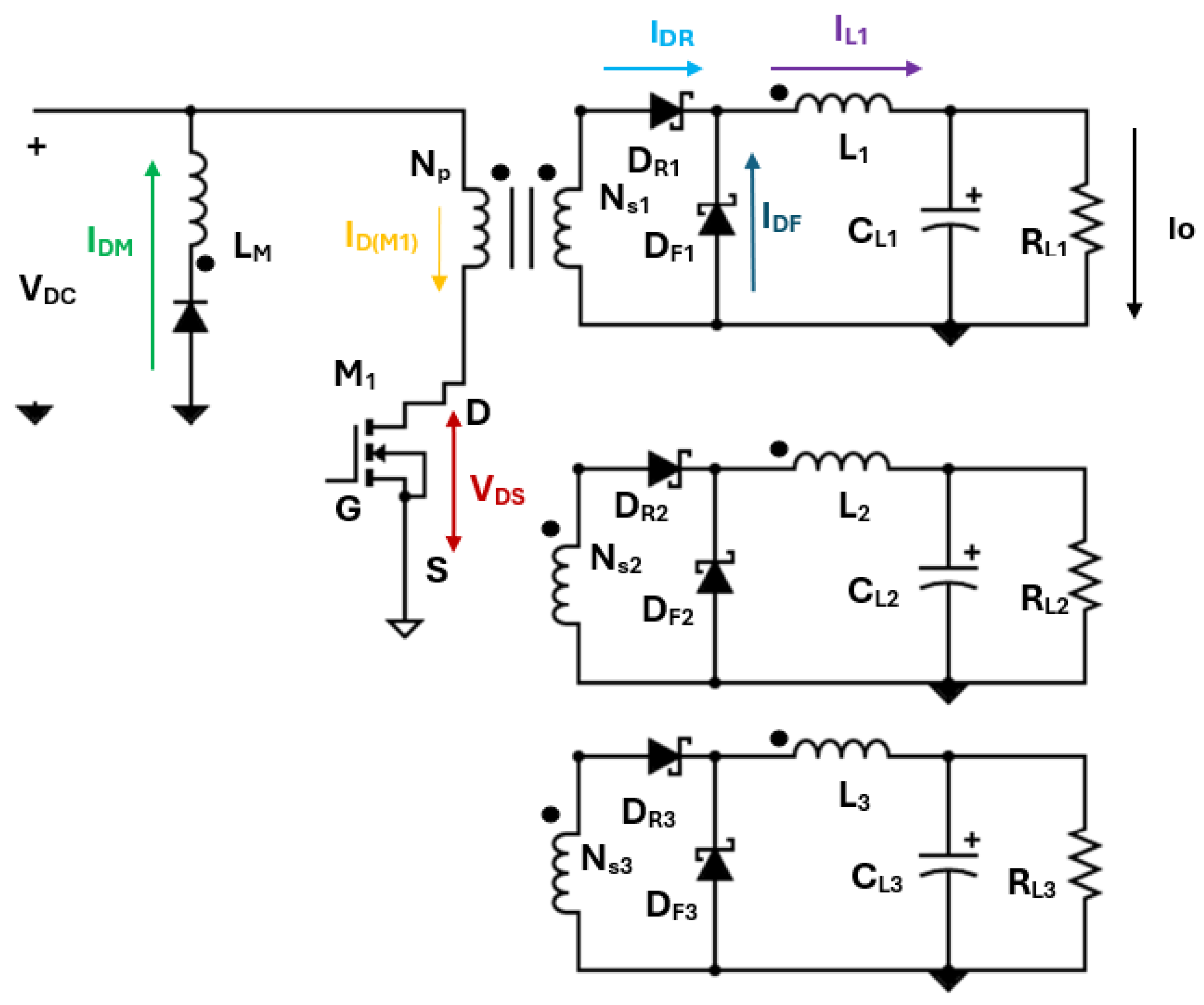
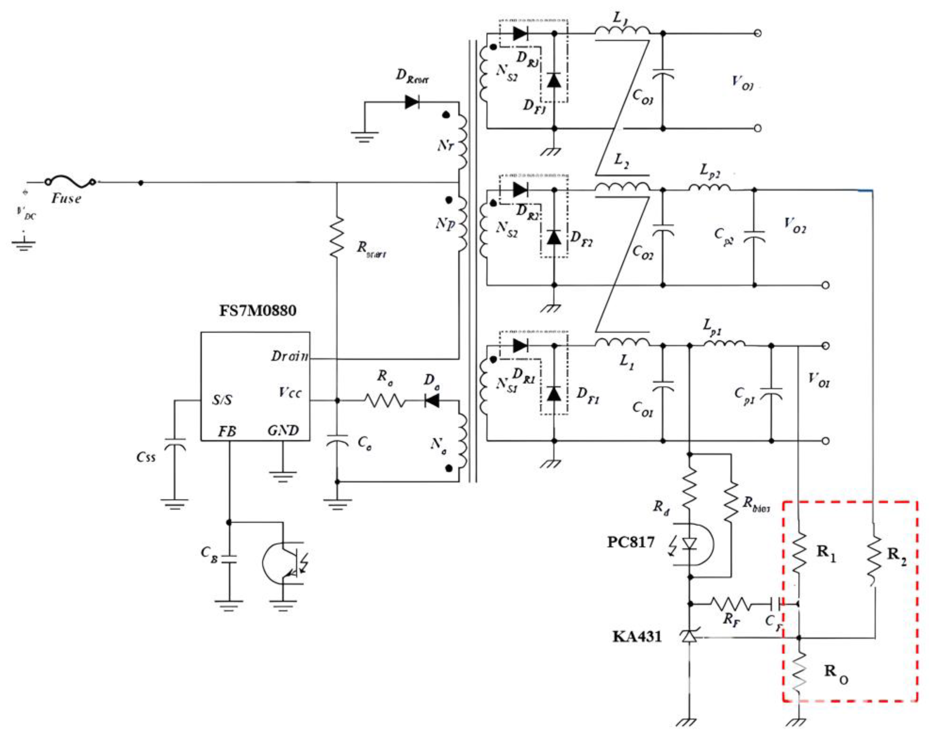
2. Circuit Description
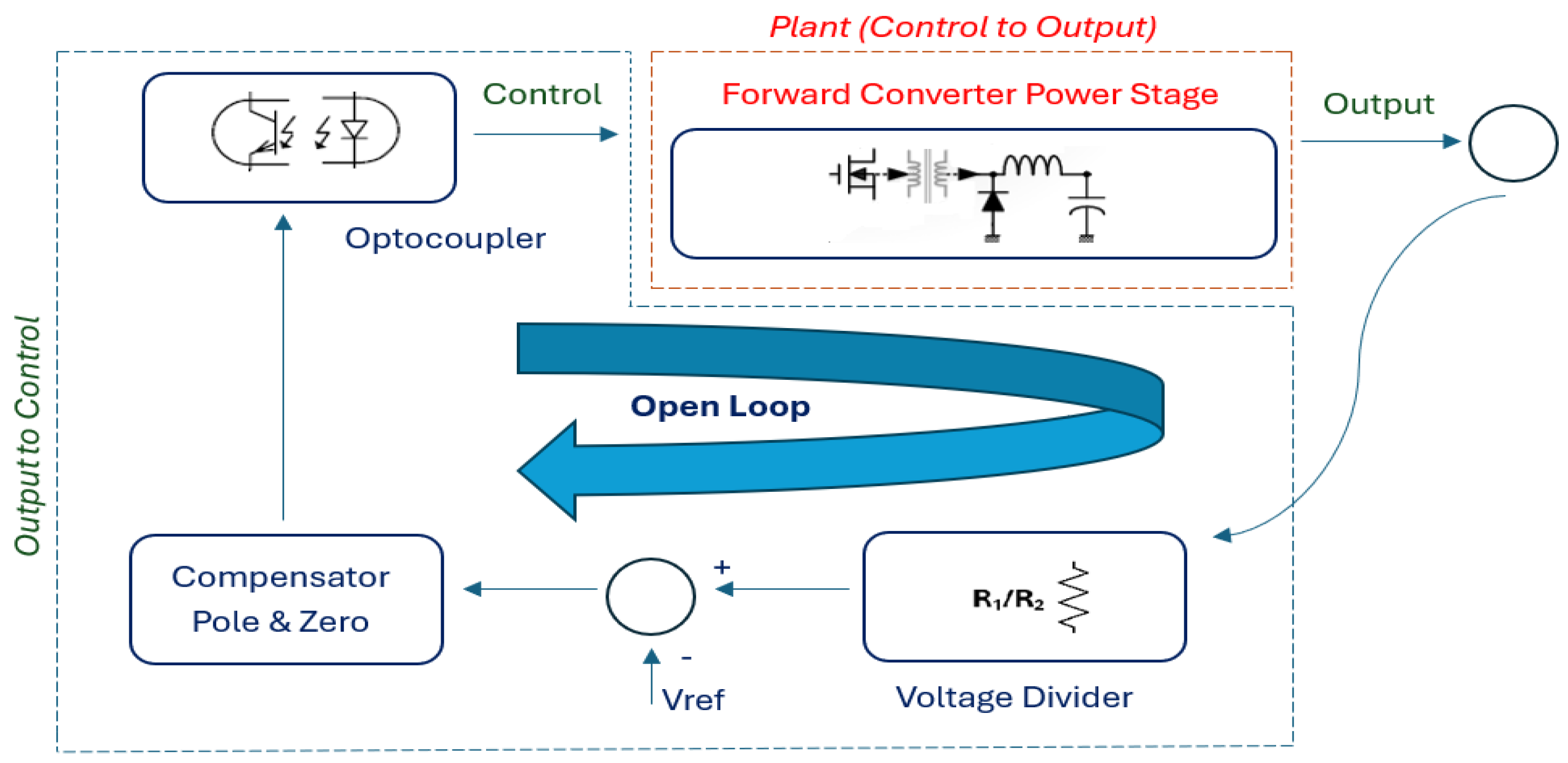
3. Mathematical Modelling of Multi-Output Forward Converter with Weighted Control
4. Simulation and Experiment Analysis
- (1)
- In the multiple-output forward converter, the information of voltage value for this winding was not received.
- (2)
- The current passing through the diode in its winding always changes under different loads.
- (3)
- The internal resistance on the transformer of the winding is proportionally different to the resistance in the other windings.
- (4)
- The secondary winding to which it is connected causes voltage changes due to common inductance.
- (5)
- When designing the transformer winding, the obligation of making a half winding or full winding causes voltage value changes.
- (6)
- Primary and secondary windings can never be perfectly coupled. There is leakage inductance between the windings.
5. Conclusions
Author Contributions
Funding
Data Availability Statement
Acknowledgments
Conflicts of Interest
Abbreviations
| Cross sectional area of the core in mm2 | |
| Saturation flux density in tesla | |
| Maximum flux density swing in tesla in normal operation | |
| Capacitance of the output capacitor | |
| Maximum duty cycle ratio | |
| Minimum duty cycle ratio | |
| Estimated efficiency | |
| Switching frequency | |
| Maximum peak current of MOSFET | |
| Rms current value for reset winding | |
| Rms current value for n transformer winding | |
| FPS current limit level | |
| Output load current | |
| Current ripple factor | |
| Transformer primary side inductance | |
| The minimum number of turns for the transformer’s primary side to avoid saturation | |
| Number of turns for primary side | |
| Number of turns for reset winding | |
| Number of turns for the reference output | |
| Number of turns for n output inductor | |
| Number of turns for output inductor 1 | |
| Maximum output power | |
| Maximum input power | |
| Effective series resistance (ESR) of the output capacitor | |
| Minimum DC link voltage | |
| Maximum DC line voltage | |
| Output voltage for n.st output | |
| First output voltage | |
| n diode forward voltage drop | |
| First diode forward voltage drop | |
| Nominal voltage for Vcc | |
| Diode forward voltage drop of Vcc winding | |
| Maximum voltage stress of MOSFET |
Appendix A
References
- Park, J.E.; Han, J.K.; Choi, S.H.; Moon, G.W. Two-Switch Forward Converter With an Integrated Buck Converter for High Bus Voltage in Satellites. IEEE Trans. Power Electron. 2023, 38, 2041–2051. [Google Scholar] [CrossRef]
- Zhu, G.; Liu, S. A Novel Secondary Side Series LCD Forward Converter with High Efficiency and Magnetic Reset. Appl. Sci. 2023, 13, 7640. [Google Scholar] [CrossRef]
- Khorasani, R.R.; Adib, E.; Farzanehfard, H. ZVT Resonant Core Reset Forward Converter With a Simple Auxiliary Circuit. IEEE Trans. Ind. Electron. 2018, 65, 242–250. [Google Scholar] [CrossRef]
- Zong, Y.; Li, K.; Wang, Q.; Meng, J. Multi-Mode Lithium-Ion Battery Balancing Circuit Based on Forward Converter with Resonant Reset. Appl. Sci. 2023, 13, 10430. [Google Scholar] [CrossRef]
- Lin, J.Y.; Liu, P.J.; Yang, C.Y. A Dual-Transformer Active-Clamp Forward Converter With Nonlinear Conversion Ratio. IEEE Trans. Power Electron. 2016, 31, 4353–4361. [Google Scholar] [CrossRef]
- Rodríguez, J.; García-Mere, J.R.; Lamar, D.G.; Hernando, M.M.; Sebastián, J. High Step-Down Isolated PWM DC–DC Converter Based on Combining a Forward Converter With the Series-Capacitor Structure. IEEE Access 2023, 11, 131045–131063. [Google Scholar] [CrossRef]
- Zhou, G.; Tian, Q.; Li, H. Three-Port Forward Converters With Compact Structure and Extended Duty Cycle Range. IEEE Trans. Ind. Electron. 2023, 70, 566–581. [Google Scholar] [CrossRef]
- Qian, T.; Wu, Q. A Boost Type Resonant Forward Converter With Topology Combination. IEEE Trans. Circuits Syst. II Express Briefs 2018, 65, 2008–2011. [Google Scholar] [CrossRef]
- Cho, S.Y.; Lee, I.O.; Kim, J.K.; Moon, G.W. A New Standby Structure Based on a Forward Converter Integrated With a Phase-Shift Full-Bridge Converter for Server Power Supplies. IEEE Trans. Power Electron. 2013, 28, 336–346. [Google Scholar] [CrossRef]
- Wu, H.; Xu, P.; Liu, W.; Xing, Y. Series-Input Interleaved Forward Converter With a Shared Switching Leg for Wide Input Voltage Range Applications. IEEE Trans. Ind. Electron. 2013, 60, 5029–5039. [Google Scholar] [CrossRef]
- Mouser. Available online: https://www.mouser.com/pdfdocs/2-10.pdf?srsltid=AfmBOopVjEUNuLLyNo2rcWN6o-zr1D6L166AE5SQrocKxvkf2VvrhBRe (accessed on 22 November 2024).
- Litran, S.P.; Duran, E.; Semio, J.; Diaz-Martin, C. Multiple-Output DC–DC Converters: Applications and Solutions. Electronics 2022, 11, 1258. [Google Scholar] [CrossRef]
- Rashid, M.H. Power Electronics Handbook, 3rd ed.; Elsevier: New York, NY, USA, 2011; pp. 167–171. [Google Scholar]
- Zheng, Y.; Ho, M.; Guo, J.; Mak, K.L.; Leung, K.N. A single inductor multiple-output auto-buck-boost dc-dc converter with auto phase allocation. IEEE Trans. Power Electron. 2016, 31, 2296–2313. [Google Scholar] [CrossRef]
- Kim, J.-K.; Lee, J.-B.; Moon, G.-W. Zero-voltage switching multioutput flyback converter with integrated auxiliary buck converter. IEEE Trans. Power Electron. 2014, 29, 3001–3010. [Google Scholar] [CrossRef]
- Shen, Z.; Chang, X.; Wang, W.; Tan, X.; Yan, N.; Min, H. Predictive digital current control of single-inductor multiple-output converters in ccm with low cross regulation. IEEE Trans. Power Electron. 2012, 27, 1917–1925. [Google Scholar] [CrossRef]
- Goh, T.Y.; Ng, W.T. Single discharge control for single-inductor multiple-output DC-DC buck converters. IEEE Trans. Power Electron. 2018, 33, 2307–2316. [Google Scholar] [CrossRef]
- Ma, D.; Ki, W.-H.; Tsui, C.-Y.; Mok, P.K.T. Single-inductor multiple output switching converters with time-multiplexing control in discontinuous conduction mode. IEEE J. Solid-State Circuits 2003, 38, 89–100. [Google Scholar]
- Trevisan, D.; Mattarella, P.; Tanti, P. Digital control of single-inductor multiple-output step-down dc-dc converters in CCM. IEEE Trans. Ind. Electron. 2008, 55, 3476–3483. [Google Scholar] [CrossRef]
- Wang, B.; Anomalepidid, V.R.K.; Xian, L.; Peng, X.; Tan, K.T.; So, P.L. Model predictive voltage control for single-inductor multiple-output dc-dc converter with reduced cross regulation. IEEE Trans. Ind. Electron. 2016, 63, 4187–4197. [Google Scholar] [CrossRef]
- Huang, W.; Qihoo, J.A.A.; Dang, Z. CCM-DCM power-multiplexed control scheme for single-inductor multiple-output dc-dc power converter with no cross regulation. IEEE Trans. Ind Appl. 2017, 53, 1219–1231. [Google Scholar] [CrossRef]
- Wang, B.; Xian, L.; Anomalepidid, V.R.K.; Tseng, K.J.; Ukil, A.; Goo, H.B. A digital method of power-sharing and cross-regulation suppression for single-inductor multiple-input multiple-output dc-dc converter. IEEE Trans. Ind. Electron. 2017, 64, 2836–2847. [Google Scholar] [CrossRef]
- Zhou, S.; Zhou, G.; Xu, D.; Ran, X.; Xu, S. Voltage-mode variable frequency control for single-inductor dual-output buck converter with fast transient response. In Proceedings of the IEEE 3rd International Future Energy Electronics Conference and ECCE Asia (IFEEC 2017—ECCE Asia), Kaohsiung, Taiwan, 3–7 June 2017; pp. 1339–1344. [Google Scholar]
- Sarkar, A.; Akalapathi, B.T.; Anand, S. Gan-Based Multiple Output Flyback Converter with Independently Controlled Outputs. IEEE Trans. Ind. Electron. 2022, 69, 2565–2576. [Google Scholar] [CrossRef]
- Leng, C.M.; Chiu, H.J. Three-Output Flyback Converter with Synchronous Rectification for Improving Cross-Regulation and Efficiency. Electronics 2021, 10, 430. [Google Scholar] [CrossRef]
- Paul, C.; Chao, P.; Chen, W.; Wu, R. A Battery Charge Controller Realized by a Flyback Converter with Digital Primary Side Regulation for Mobile Phones. Microsyst. Technol. 2014, 20, 1689–1703. [Google Scholar]
- Chen, G.; Chen, L.; Deng, Y.; He, X.; Wang, Y.; Zhang, J. Single coupled-inductor dual output soft-switching DC–DC converters with improved cross-regulation and reduced components. IET Power Electron. 2017, 10, 1665–1678. [Google Scholar] [CrossRef]
- Wang, W.; Lu, D.; Chai, Q.; Lin, Q.; Cai, F. Analysis of fly-buck converter with emphasis on its cross-regulation. IET Power Electron. 2017, 10, 292–301. [Google Scholar] [CrossRef]
- Kolincio, M.; Chrzan, P.J.; Musznicki, P. Multitransformer Primary-Side Regulated Flyback Converter for Supplying Isolated IGBT and MOSFET Drivers. IEEE Trans. Ind. Electron. 2020, 67, 1005–1012. [Google Scholar] [CrossRef]
- Guo, X.; Luan, F.; Liu, J.; Liu, M. Analysis and improvement of cross-regulation effect in the primary side-regulated multi-output flyback converter. Int. J. Circuit Theory Appl. 2017, 45, 1299–1312. [Google Scholar] [CrossRef]
- Granello, P.; Schirone, L. Modelling and Experimental Validation of Dual-Output Flyback Converters with Capacitive Coupling for Improved Cross-Regulation. Electronics 2024, 13, 3503. [Google Scholar] [CrossRef]
- Loza, B.; Cherrez, J.P.; Gonzalez, L.G. Design and Analysis of Performance of a Forward Converter with Winding Tertiary. In Proceedings of the IEEE International Autumn Meeting on Power, Electronics and Computing (ROPEC), Ixtapa, Mexico, 8–10 November 2017. [Google Scholar]
- Choi, H.S. Design Guidelines for Off-line Forward Converters Using Fairchild Power Switch. Available online: https://www.onsemi.com/pub/Collateral/AN-4134.PDF (accessed on 22 November 2024).
- Lind, A. Single Transistor Forward Converter Design. Available online: https://www.mouser.com/pdfdocs/2-10.pdf (accessed on 6 August 2024).


| Parameters | Diameter | Parallel | Irms (A) | A/mm2 | Turn |
|---|---|---|---|---|---|
| Primary Winding | 0.445 mm | 9 | 1.89 | 1.29 | 22 T |
| Reset Winding | 0.445 mm | 1 | 0.07 | 0.42 | 11 T |
| Vcc Winding | 0.445 mm | 1 | 0.1 | 0.62 | 4 T |
| First Output Winding | 0.445 mm | 4 | 0.67 | 1.03 | 16 T |
| Second Output Winding | 0.445 mm | 8 | 1.34 | 1.03 | 13 T |
| Third Output Winding | 0.445 mm | 8 | 1.34 | 1.03 | 4 T |
| Parameters | Diameter | Parallel | Irms (A) | A/mm2 | Turn |
|---|---|---|---|---|---|
| Winding for L1 | 0.445 mm | 5 | 1 | 1.23 | 24 |
| Winding for L2 | 0.445 mm | 10 | 2 | 1.23 | 19.5 |
| Winding for L3 | 0.445 mm | 10 | 2 | 1.23 | 6 |
| Parameters | Reverse Voltage (V) | Rms Current (A) |
|---|---|---|
| Vcc Diode | 31 | 0.1 |
| First Output Diode | 43 | 0.67 |
| Second Output Diode | 35 | 1.34 |
| Third Output Diode | 11 | 1.34 |
| Parameters | Esr (mΩ) | Current Ripple (A) | Voltage Ripple (V) |
|---|---|---|---|
| First Output Capacitor | 40 | 0.1 | 0.01 |
| Second Output Capacitor | 40 | 0.1 | 0.02 |
| Third Output Capacitor | 40 | 0.1 | 0.02 |
| Parameters | Value |
|---|---|
| DC Input Voltage | 50–80 V |
| DC Output Voltage/Current | 15 V/1 A, 12 V/2 A, 3,3 V/2 A |
| Np, N1, N2, N3, Np, Naux | 22, 16, 13, 4, 22, 8 turn |
| IC PWM Controller | FS7M0880 |
| DR1, DR2, DR3 | MBR40250TG Schottky Diode |
| DF1, DF2, DF3 | MBR40250TG Schottky Diode |
| Dreset | UF4007 Diode |
| CO1, CO2, CO3 | 2200 µF/25 V |
| CP1, CP2 | 330 µF/25 V |
| LP1, LP2 | 1.2 µH/10 A |
| Fixed Operating Frequency | 67 kHz |
| Output Power under Full Load | 45.6 W |
| Parameters | Value |
|---|---|
| Voltage divider resistor (R1,R2) | 22 kΩ |
| Voltage divider resistor (Ro) | 2.49 kΩ |
| Optocoupler diode resistor (RD) | 1 kΩ |
| KA431 Bias resistor (RBias) | 0.68 kΩ |
| Feedback pin capacitor (CB) | 39 nF |
| Feedback capacitor (CF) | 47 nF |
| Feedback resistor (RF) | 1 kΩ |
| Parameters | Value |
|---|---|
| Control-to-output DC gain | 9 |
| Control-to-output DC zero | 1809 Hz |
| Control-to-output pole | 15 Hz |
| Feedback integrator gain (fi) | 462 Hz |
| Feedback zero (fz) | 147.3 Hz |
| Feedback pole (fpo) | 1361 Hz |
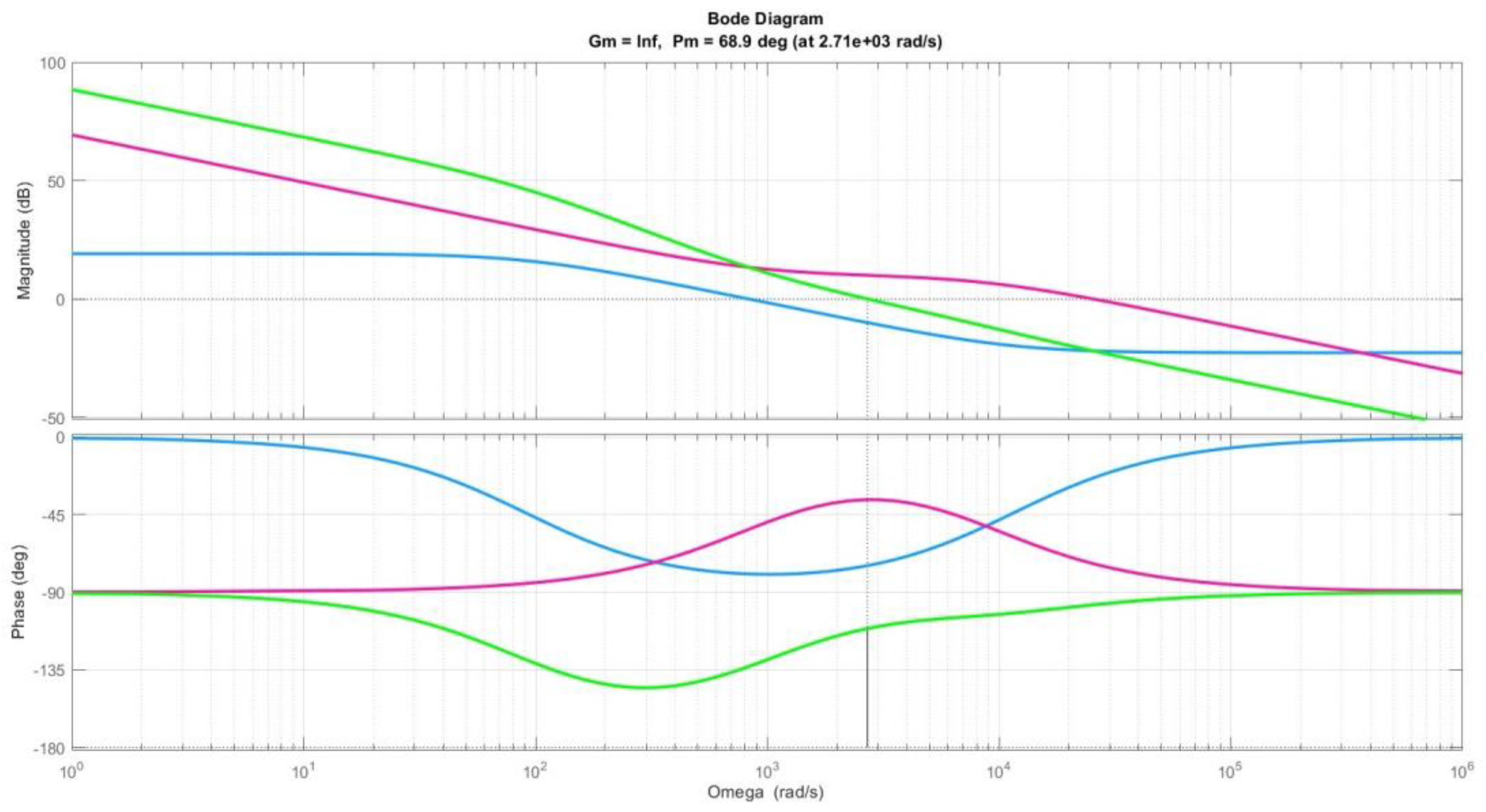
| Parameters | Crossover Frequency (fc) | PM | GM |
|---|---|---|---|
| Control-to-Output | 133 Hz | 101° | Inf |
| Open-Loop | 431 Hz | 68.9° | Inf |
| 3.3 V | 12 V | 15 V | |||||||
|---|---|---|---|---|---|---|---|---|---|
| Load (%) | Load (A) | Voltage (V) | Pout (W) | Load (A) | Voltage (V) | Pout (W) | Load (A) | Voltage (V) | Pout (W) |
| 10% | 0.2 | 3.41 | 0.68 | 0.2 | 12.04 | 2.41 | 0.1 | 14.98 | 1.50 |
| 25% | 0.5 | 3.37 | 1.69 | 0.5 | 12.02 | 6.01 | 0.25 | 14.99 | 3.75 |
| 50% | 1 | 3.31 | 3.31 | 1 | 12.01 | 12.01 | 0.5 | 15.00 | 7.50 |
| 75% | 1.5 | 3.26 | 4.89 | 1.5 | 12.01 | 18.02 | 0.75 | 14.99 | 11.24 |
| 100% | 2 | 3.23 | 6.46 | 2 | 12.01 | 24.02 | 1 | 14.98 | 14.98 |
| 3.3 V | 12 V | 15 V | |||||||
|---|---|---|---|---|---|---|---|---|---|
| Load (%) | Load (A) | Voltage (V) | Pout (W) | Load (A) | Voltage (V) | Pout (W) | Load (A) | Voltage (V) | Pout (W) |
| 10% | 0.2 | 3.41 | 0.68 | 0.2 | 12.04 | 2.41 | 0.1 | 14.98 | 1.50 |
| 25% | 0.5 | 3.37 | 1.69 | 0.5 | 12.02 | 6.02 | 0.25 | 15.00 | 3.75 |
| 50% | 1 | 3.30 | 3.30 | 1 | 12.01 | 12.01 | 0.5 | 15.01 | 7.51 |
| 75% | 1.5 | 3.26 | 4.89 | 1.5 | 11.99 | 17.99 | 0.75 | 14.99 | 11.24 |
| 100% | 2 | 3.23 | 6.46 | 2 | 11.99 | 23.98 | 1 | 14.98 | 14.98 |
| 3.3 V | 12 V | 15 V | ||||
|---|---|---|---|---|---|---|
| Load (%) | Voltage (V) | Cross-Regulation (%) | Voltage (V) | Cross-Regulation (%) | Voltage (V) | Cross-Regulation (%) |
| 10% | 3.56 | 7.88 | 12.02 | 0.17 | 14.92 | −0.53 |
| 25% | 3.54 | 7.27 | 12.01 | 0.08 | 14.94 | −0.40 |
| 50% | 3.51 | 6.36 | 12.01 | 0.08 | 14.90 | −0.67 |
| 75% | 3.50 | 6.06 | 12.00 | 0.00 | 14.89 | −0.73 |
| 100% | 3.49 | 5.76 | 12.00 | 0.00 | 14.89 | −0.73 |
| 3.3 V | 12 V | 15 V | ||||
|---|---|---|---|---|---|---|
| Load (%) | Voltage (V) | Cross-Regulation (%) | Voltage (V) | Cross-Regulation (%) | Voltage (V) | Cross-Regulation (%) |
| 10% | 3.55 | 7.58 | 12.01 | 0.08 | 14.95 | −0.33 |
| 25% | 3.54 | 7.27 | 12.01 | 0.08 | 14.95 | −0.33 |
| 50% | 3.53 | 6.97 | 12.04 | 0.33 | 14.98 | −0.13 |
| 75% | 3.51 | 6.37 | 12.05 | 0.42 | 14.98 | −0.13 |
| 100% | 3.51 | 6.36 | 12.05 | 0.42 | 14.96 | −0.27 |
| Reference | [24] | [25] | [31] | This Work |
|---|---|---|---|---|
| Converter type | Flyback converter | Flyback converter | Flyback converter | Forward converter |
| Total output winding | 2 | 3 | 2 | 3 |
| Output power | 40 W | 68 W | 8.5 W | 45.6 W |
| Cross-regulation | %0.2 | %2.26 | below 5% | 3.33% |
| Peak efficiency | 86.9% | 87% | none | 86.8% |
| Switching frequency | 600 kHz | 30 kHz | 1 MHz | 66 kHz |
Disclaimer/Publisher’s Note: The statements, opinions and data contained in all publications are solely those of the individual author(s) and contributor(s) and not of MDPI and/or the editor(s). MDPI and/or the editor(s) disclaim responsibility for any injury to people or property resulting from any ideas, methods, instructions or products referred to in the content. |
© 2025 by the authors. Licensee MDPI, Basel, Switzerland. This article is an open access article distributed under the terms and conditions of the Creative Commons Attribution (CC BY) license (https://creativecommons.org/licenses/by/4.0/).
Share and Cite
Dindar, S.; Hardalac, F.; Aksoy, E.; Ayturan, K. Investigation of Multi-Output Single-Switch Forward Converter in Terms of Cross-Regulation Using Weighted Control Method. Appl. Sci. 2025, 15, 365. https://doi.org/10.3390/app15010365
Dindar S, Hardalac F, Aksoy E, Ayturan K. Investigation of Multi-Output Single-Switch Forward Converter in Terms of Cross-Regulation Using Weighted Control Method. Applied Sciences. 2025; 15(1):365. https://doi.org/10.3390/app15010365
Chicago/Turabian StyleDindar, Salih, Fırat Hardalac, Ertugrul Aksoy, and Kubilay Ayturan. 2025. "Investigation of Multi-Output Single-Switch Forward Converter in Terms of Cross-Regulation Using Weighted Control Method" Applied Sciences 15, no. 1: 365. https://doi.org/10.3390/app15010365
APA StyleDindar, S., Hardalac, F., Aksoy, E., & Ayturan, K. (2025). Investigation of Multi-Output Single-Switch Forward Converter in Terms of Cross-Regulation Using Weighted Control Method. Applied Sciences, 15(1), 365. https://doi.org/10.3390/app15010365