Article

Intelligent Dynamic Power Control with Cell Range Expansion for Small-Cells in 5G HetNets

Department of Computer Science and Statistics, Chosun University, Gwangju 61452, Republic of Korea
*
Author to whom correspondence should be addressed.
Appl. Sci. 2024, 14(9), 3789; https://doi.org/10.3390/app14093789
Submission received: 30 March 2024 / Revised: 23 April 2024 / Accepted: 26 April 2024 / Published: 29 April 2024

Abstract

:
In 5G heterogeneous networks (HetNets), small-cell base stations (SBSs) are deployed in the coverage of macro base stations (MBSs) to improve the system performance. However, some macro user equipments (MUEs) have strong interference from neighboring SBSs and thus the performance of MBSs decreases. Thus, in this paper, we propose a novel intelligent dynamic power control (DPC) with cell range expansion (CRE) to improve the downlink performance of both small-cell user equipments (SUEs) and CRE user equipments (CUEs) in 5G HetNets. That is, in the proposed DPC scheme, each MUE first collects the received signal strength indicator (RSSI) measurements from neighboring SBSs and sends them to the serving MBS. Then, the MBS finds MUEs with strong interference from neighboring SBSs based on a given target threshold of CRE and offloads a fraction of MUEs from MBSs to SBSs. In addition, SBSs divide their SUEs and CUEs into two groups, i.e., inner and outer groups, to assign different subchannels and dynamically allocate the appropriate transmission power to increase the performance of both SUEs and CUEs. Through simulation results, it is shown that the proposed DPC scheme outperforms others in terms of the capacity and outage probability of SUEs and CUEs.

1. Introduction

Recently, the fifth generation (5G) wireless cellular technology has been developed to increase the speed and reliability of the rapidly increasing mobile data traffic from various smart devices such as smartphones, tablet PCs, and Internet of Things (IoT) devices [1,2,3,4,5]. In addition, 5G networks adopt a heterogeneous network (HetNet) architecture where different types of small-cells, i.e., microcells, picocells, and femtocells are overlapped with the conventional macrocells [6,7,8]. The small cell is a cost-effective radio base station with low transmission power to improve the system capacity and extend the coverage. 5G networks also consider an ultra-dense network (UDN) architecture where a large number of small cells with a short coverage range are densely deployed on the coverage of macrocells [9,10]. However, in HetNets, macro base stations (MBSs) serve most smart devices in their coverage since the transmission power of MBSs is higher than that of small-cell base stations (SBSs). It means that SBSs have enough subchannels to assign each small-cell user equipment (SUE) but MBSs lack subchannels to assign for each MUE when SBSs reuse the limited frequency bands of MBSs [11]. Thus, in order to solve the load balancing problem, the third generation partnership project (3GPP) standardized cell range expansion (CRE) technology to extend the coverage of SBSs by adding a bias to the reference signal receive power (RSRP) and then a fraction of MUEs located close to SBSs are offloaded to SBSs, i.e., some MUEs become CRE user equipments (CUEs) [12,13,14,15,16]. Further, in HetNets, MBSs and SBSs have strong interference with each other  [17,18,19,20,21,22,23,24,25,26] and CUEs have more serious interference from both MBSs and neighboring SBSs than SUEs. Therefore, it is necessary to study interference management schemes with consideration of CRE for 5G HetNets.
Research has investigated interference management schemes using static and dynamic power control for MBSs and SBSs in HetNets with time division duplex (TDD) and frequency division duplex (FDD) [27,28,29,30,31,32,33,34,35,36]. In [27,28,29,30,31], authors proposed power control schemes using almost blank subframe (ABS) to dynamically or statically configure frames with empty or low transmission power to reduce interference to CUEs. In [32], authors proposed a static power control scheme that allocates the same transmission power for all subchannels of SBSs according to the CRE bias and thus it is difficult to allocate the appropriate transmission power to both CUEs and SUEs even though the power control algorithm is simple. In [33], the authors proposed a dynamic power control (DPC) scheme to dynamically allocate different transmission power of every subchannel for CUEs only and thus it has a system performance higher than other schemes with static power control. In [34,35], authors proposed DPC schemes in which MBSs assign different groups of subchannels to MUEs and CUEs and allocate the appropriate transmission power for CUEs. In [36], authors proposed DPC schemes in which MBSs and SBSs assign the same group of subchannels to MUEs and CUEs and then SBSs allocate the appropriate transmission power for CUEs. Most of the previous work only considered the performance of CUEs using the power control of either MBSs or SBSs after CRE but did not consider the performance of SUEs served by the SBSs. Table 1 summarizes the methods used in existing studies. In [37,38,39], as a broader concept than CRE, authors introduced user association schemes in which MUEs or SUEs establish connections to MBSs and SBSs for various purposes, i.e., spectrum efficiency, energy efficiency, quality of service (QoS) provision and fairness, using RSSI, power control, and bias.
In this paper, we propose a novel intelligent DPC scheme with CRE to improve the performance of both SUEs and CUEs in the downlink (DL) 5G HetNets. That is, in the proposed DPC scheme, each MUE first collects the received signal strength indicator (RSSI) measurements from SBSs and sends them to the serving MBS. Then, the MBS finds MUEs with strong interference from neighboring SBSs based on a given target threshold of CRE and offloads a fraction of MUEs from MBSs to SBSs. In addition, SBSs divide their SUEs and CUEs into two groups, i.e., inner and outer groups, to assign different subchannels and dynamically allocate the appropriate transmission power to increase the performance of both SUEs and CUEs. Through simulation results, it is shown that the proposed DPC scheme outperforms others in terms of the capacity and outage probability of SUEs and CUEs. In other words, the proposed DPC scheme increases the mean SUE capacity by up to 119% with the same performance of the mean MUE capacity compared to other DPC schemes with CRE.
The rest of this paper is organized as follows. Section 2 introduces the system model of 5G HetNets and assumptions adopted in this paper. Section 3 describes the proposed DPC with CRE while Section 4 evaluates the simulation results with various parameters. Finally, Section 5 contains the conclusion with future research directions. Table 2 summarizes the main symbols and notations in this paper.

2. System Model

2.1. System Topology and Channel Assignment

We consider the DL of 5G HetNets based on orthogonal frequency division multiple access and FDD (OFDMA-FDD). Figure 1 shows the system architecture in which SBSs are overlapped on the coverage of MBSs. We assume that there are M hexagonal macrocells ( M = 7 ) where the target macrocell is surrounded by six macrocells and a set of M MBSs, M = | M | , M = { 1 , 2 , , M } , is located at the center of each macrocell. Let d I S denote the inter-site distance between MBSs. In addition, sets of N MUEs, N = { 1 , 2 , , N } , and S SBSs, S = { 1 , 2 , , S } are uniformly distributed in the coverage of each site of MBSs. SBSs are installed in outdoor environments and have a set of T SUEs, T = { 1 , 2 , , T } in the coverage of each SBS (SBSs have no overlapping coverages with each other). Each MBS has a three-sectored directional antenna and thus the coverage of MBSs is divided into three sites, i.e., sites 1, 2 and 3, while SBSs have an omnidirectional antenna. Figure 2 shows the channel assignments of MBSs and SBSs (including CUEs) in 5G HetNets. Each MBS uses a set of K subchannels, K = { 1 , 2 , , K } , and K subchannels are divided into three subchannel groups (SGs) (each SG has one-third subchannels), i.e., A, B and C, assigned to site 1, 2, and 3 of MBSs, respectively. On the other hand, all SBSs use K subchannels to serve their SUEs and CUEs without the transmission power control and thus MBSs and SBSs have strong interference with each other.

2.2. SINR Model, System Capacity and Outage Probability

In order to analyze the system performance of 5G HetNets, we first calculate the signal-to-interference plus noise ratio (SINR) of MUEs and SUEs. Let γ m n k and γ m s t k denote the SINR of MUE n ( n N ) served by MBS m ( m M ) and the SINR of SUE t served by SBS s ( s S ) in the coverage of MBS m ( m M ) at subchannel k ( k K ), respectively. Then, γ m n k and γ m s t k can be expressed as
γ m n k = h m n A ( θ ) ψ m n k i M { m } h i n A ( θ ) ψ i n k + i M s S h i s n ψ i s n k + σ 2 , m M , s S , n N , k K ,
γ m s t k = h m s t ψ m s t k i M h i t A ( θ ) ψ i t k + i M l S { s } h i l t ψ i l t k + σ 2 , m M , s S , t T , k K ,
where h m n = P M B S L m n and h m s t = P S B S L m s t are the RSSI measurements between MBS m and MUE n and between SBS s and SUE t in the coverage of MBS m, respectively. P M B S and P S B S are the transmission power for each subchannel of MBSs and SBSs, respectively. L m n and L m s t denote the path losses between MBS m and MUE n and between SBS s and SUE t in the coverage of MBS m in dB, respectively. Further, ψ m n k and ψ i s t k are indicator variables for the channel assignment, e.g., ψ m n k = 1 and ψ i s t k = 1 if MBS m assigns subchannel k to MUE n and if SBS s of MBS i assigns subchannel k to SUE t, respectively, and otherwise is 0. The SINR of CUEs served by SBSs is also calculated by (2). A ( θ ) is the azimuth antenna pattern from MBSs to MUEs (or SUEs) in dB while σ 2 is the white noise power. Then, A ( θ ) can be expressed as
A ( θ ) = A m g min 12 ( θ θ 3 dB ) 2 , A m a , 180 θ 180 ,
where A m g and A m a are the maximum antenna gain and maximum attenuation in dB, respectively, while θ and θ 3 d B = 70 are the azimuth antenna pattern of MBSs and 3 dB beamwidth, respectively [40].
Through (1) and (2), we use Shannon’s formula to calculate the capacities of MUE n served by MBS m, C m n , and SUE t served by SBS s of MBS m, C m s t . Then, C m n and C m s t can be expressed as
C m n = k K W ψ m n k · log 2 ( 1 + γ m n k ) , m M , n N ,
C m s t = k K W ψ m s t k · log 2 ( 1 + γ m s t k ) , m M , s S , t T ,
where W is the bandwidth of each subchannel.
In addition, we calculate the outage probability of MUEs and SUEs (including CUEs), P o u t M U E and P o u t S U E . Then, P o u t M U E and P o u t S U E can be expressed as
p o u t M U E = P r ( γ m n k < Γ t h ) , m M , n N ,
p o u t S U E = P r ( γ m s t k < Γ t h ) , m M , s S , t T ,
where Γ t h is a given target SINR threshold of MUEs and SUEs.

3. Proposed Intelligent Dynamic Power Control with Cell Range Expansion

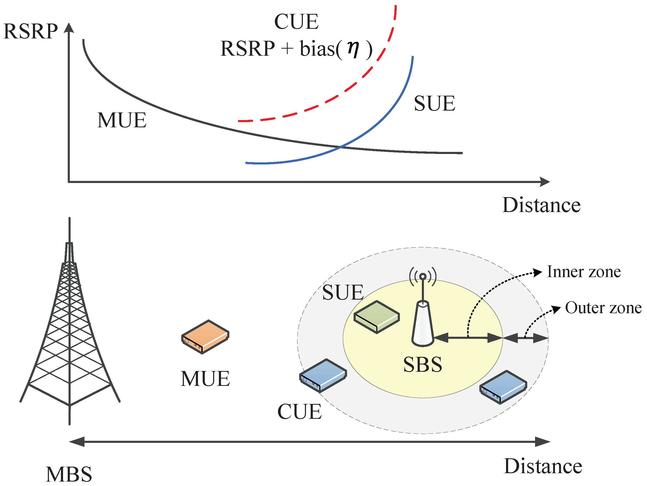
In this section, we propose the intelligent DPC scheme with CRE to improve the performance of SUEs and CUEs for 5G HetNets. Figure 3 shows an example of the CRE operation in the proposed DCA scheme. In general, the RSRP of MUEs decreases gradually as the distance between MBSs and MUEs increases. Thus, it is necessary to offload MUEs with low RSRP from MBSs to SBSs using CRE to resolve the load and increase the performance of the remaining MUEs. The coverage of SBSs is virtually divided into inner and outer zones. Let η denote a given target bias to offload MUEs to SBSs. The area of the inner zone is the original coverage of SBSs, while the area of the outer zone is the boundary with RSRP + bias, i.e., extended coverage of SBSs, for CUEs. The proposed DPC scheme has two steps for CRE and DPC operations.
In step 1, in the proposed DPC scheme, the MBS finds some MUEs to offload them to SBSs using CRE. Let ξ m n M B S and ξ m s n S B S denote the RSRP between MBS m and MUE n and between SBS s of MBS m and MUE n, respectively. Then, MBS m offloads MUE n to SBS s using CRE if the condition below is satisfied.
ξ m n M B S < = ξ m s n S B S + η .
where ξ m n M B S = h m n A ( θ ) 10 l o g ( 12 N R B ) and ξ m s n S B S = h m s n 10 l o g ( 12 N R B ) . N R B is the number of resource blocks in the channel bandwidth. Then, SBSs assign subchannels in different SGs for both SUEs and CUEs in the inner and outer zones. That is, SBSs assign subchannels in the same SG of MBSs in each site to their SUEs and CUEs in the inner zone while subchannels in different SGs are to their SUEs and CUEs in the outer zone. For example, in site 1, SBSs assign subchannels in SG A to SUEs and CUEs in the inner zone while subchannels in SG B and C to SUEs and CUEs in the outer zone. Thus, SBSs first calculate the SINRs of SUEs and CUEs using the same subchannels of MBSs and find some SUEs and CUEs that have SINRs less than a given threshold, Γ s t h to assign subchannels in other two SGs. In other words, SUEs and CUEs in the outer zone use different subchannels of MBSs to reduce interference between MBSs and SBSs.
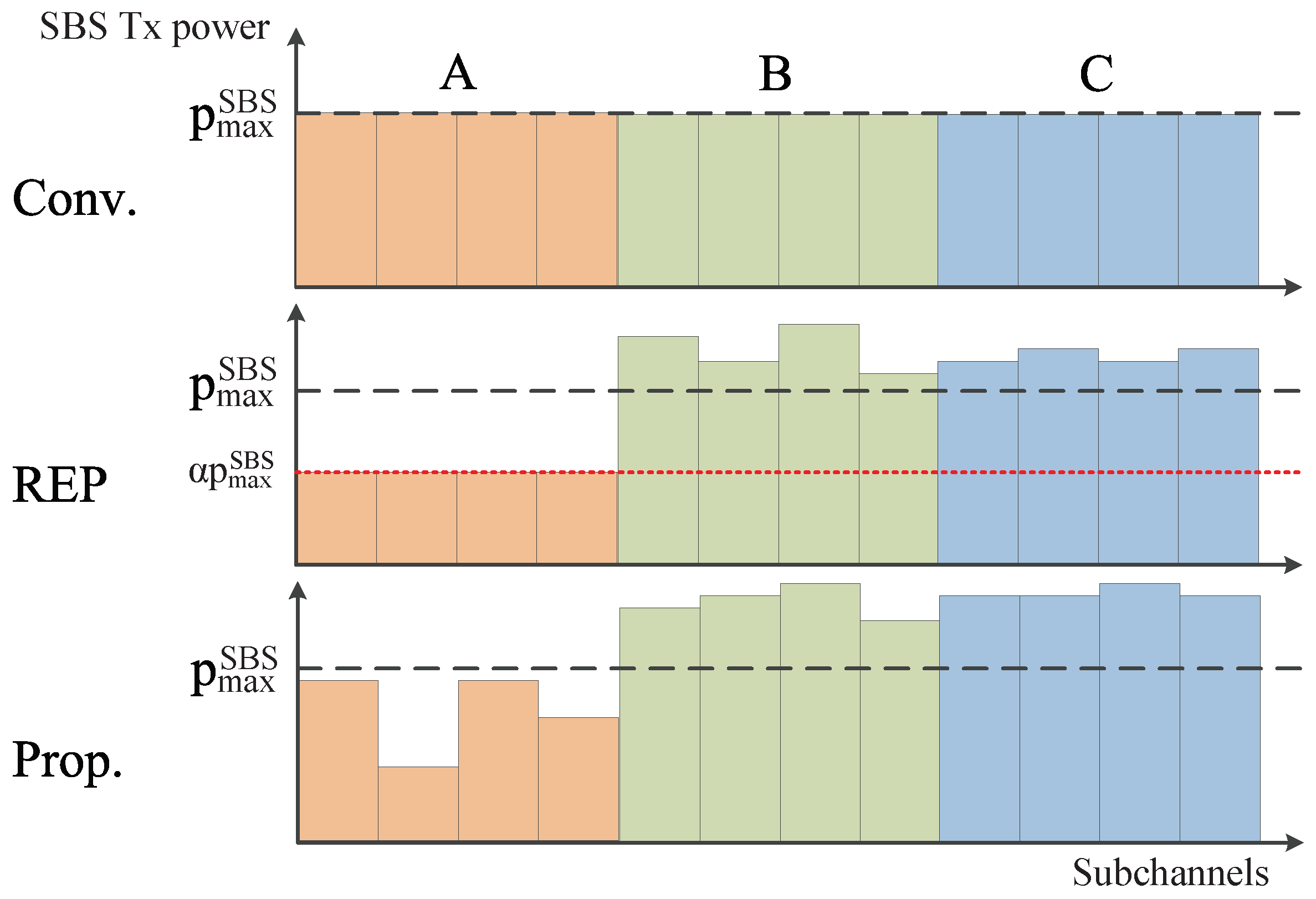
In step 2, SBSs dynamically allocate the appropriate transmission power for SUEs and CUEs. Figure 4 shows three different power control schemes, i.e., conventional (no power control), reduced equal power (REP) [35] and proposed DPC. In the conventional scheme, MBSs use no CRE and SBSs divide the total transmission power by the number of subchannels to fairly allocate for SUEs. In the REP scheme, SBSs allocate the transmission power statically and dynamically after CRE. That is, SBSs use a fixed transmission power obtained by α P m a x S B S for SUEs and CUEs in the inner zone. p m a x S B S is the total transmission power of SBSs and α is a parameter value to control the maximum transmission power for each subchannel. On the other hand, SBSs dynamically allocate the transmission power for subchannels over p m a x S B S using the reduced transmission power from subchannels in the outer zone. Finally, in the proposed DPC scheme, SBSs dynamically allocate the appropriate transmission power to SUEs and CUEs in both inner and outer zones after CRE. In order to find appropriate transmission power, SBSs repeat the operation of increasing or decreasing transmission power using Γ t h until γ m s t k == Γ t h . However, SBSs stop repeating to use the current transmission power for SUEs and CUEs if p m a x S B S == p S B S or p S B S is close to 0. The procedure of the proposed DPC scheme with CRE is described in Algorithm 1.
Algorithm 1: Proposed DPC scheme with CRE.
Require:  m M , n N , t T , k K
1:
// MBSs find some MUEs to offload them to SBSs.
2:
for  n = 1 : N do
3:
    for  s = 1 : S  do
4:
        MBS m calculates ξ m n M B S and ξ s n S B S ;
5:
        if  ξ m n M B S <= ξ s n S B S + η  then
6:
           MBS m offloads MUE n to SBS s as a CUE;
7:
           for  t = 1 : T  do
8:
               Calculate γ m s t k using the same SG as MBSs according to (2);
9:
               if  γ m s t k < Γ s t h  then
10:
                   SBS s allocates different SGs from the MBS to SUE t;
11:
               else
12:
                   SBS s allocates the same SG of the MBS to SUE t;
13:
               end if
14:
           end for
15:
        end if
16:
    end for
17:
end for
18:
// SBSs dynamically assign the appropriate transmission power to SUEs and CUEs.
19:
for  s = 1 : S  do
20:
    SBS s sorts SUEs in order of their SINR;
21:
    for  t = 1 : T  do
22:
        for  k = 1 : K  do
23:
           SBS s calculates γ m s t k according to (2);
24:
           if  γ m s t k < Γ t h  then
25:
               repeat   p S B S = p S B S + Δ p   and calculate γ m s t k until γ m s t k == Γ t h ;
26:
           else
27:
               repeat   p S B S = p S B S Δ p   and calculate γ m s t k until γ m s t k == Γ t h ;
28:
           end if
29:
        end for
30:
    end for
31:
end for

4. Simulation Results

In this section, we investigate the performance of the proposed DPC scheme for the DL of 5G HetNets using Monte Carlo simulation with Matlab simulator. We compare the proposed DPC scheme with/without DPC (Prop. DPC and Prop.) to two different schemes, i.e., conventional (Conv.) and REP in [35] as shown in Figure 4, in terms of the mean capacity and outage probability for MUEs and SUEs (including CUEs). Further, we evaluate the performance of the proposed DPC scheme in two types to show the effect of the DPC in step 2. In other words, the proposed DPC scheme (Prop. DPC) uses both CRE and DPC in steps 1 and 2, respectively, while the proposed DPC scheme without DPC (Prop.) uses only CRE in step 1. The system topology and channel assignment for the macrocell and small-cell are shown in Figure 1 and Figure 2, respectively. The values of η and Γ s t h are important parameters that determine the coverage of SBSs to serve CUEs. Thus, we decided η = 4 and 8 dB after the experiment from Γ s t h −20 to 0 dB since we consider the coverage of SBSs to be like hotspot areas. Table 3 shows the key system parameters.
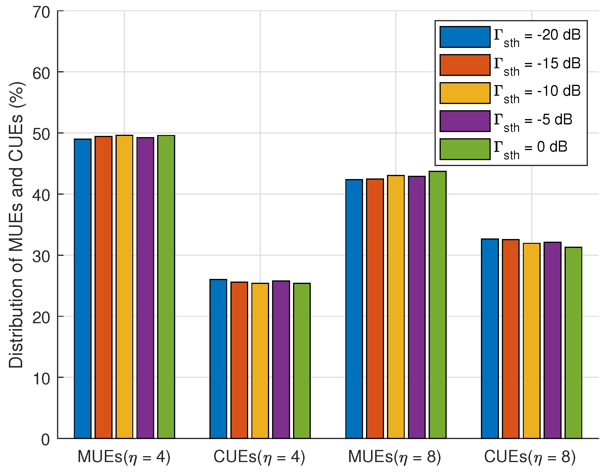
Figure 5 shows the distribution of MUEs and CUEs with different values of Γ s t h and η . The results of MUEs with η = 4 dB are higher than those with η = 8 dB. On the other hand, the results of CUEs with η = 4 dB are lower than those with η = 8 dB. The reason is that the coverage of SBSs with ξ m s n S B S + η increases when η = 8 dB and the number of CUEs offloaded from MUEs increases. In addition, the results of MUEs and CUEs are almost the same as Γ s t h increases.
Figure 6 shows the distribution of SUEs and CUEs in the inner and outer zones of SBSs based on Γ s t h . The number of both SUEs and CUEs in the inner zone decreases while that in the outer zone increases as the value of Γ s t h increases. The value of Γ s t h is used to assign different groups of subchannels and thus the number of SUEs and CUEs in the inner zone using the same subchannels of MBSs increases as the value of Γ s t h decreases. At the same time, the number of SUEs and CUEs in the outer zone using different subchannels of MBSs increases as the value of Γ s t h increases.
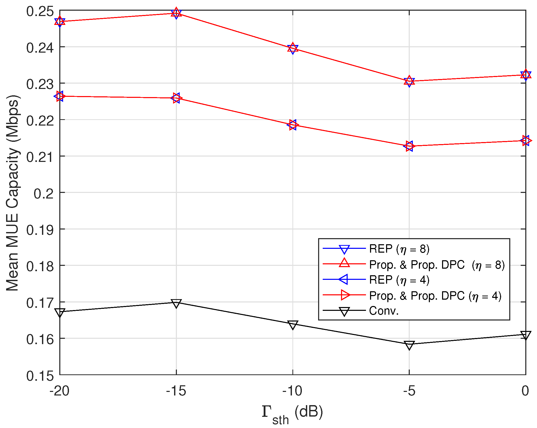
Figure 7 shows the results of the mean MUE capacity as the value of Γ s t h increases. We compare the results of the proposed DPC scheme to those of the conventional and REP schemes. The results of the conventional scheme show the worst performance because MUEs have strong interference from neighboring SBSs. On the other hand, the results of the REP and proposed scheme with/without DPC are higher than those of the conventional scheme. That is, some MUEs that have strong interference from neighboring SBSs are offloaded to SBSs as CUEs using CRE and then the results of the mean MUE capacity increase because MBSs assign subchannels to reduced number of MUEs. As a result, it is shown that the results of both REP and proposed DPC schemes with η = 4 and 8 dB are 3% and 4% higher than those of the conventional scheme, respectively. In addition, the results of both REP and proposed DPC schemes with η = 8 dB are higher than those with η = 4 dB because the number of CUEs that are offloaded with η = 8 dB is higher than that with η = 4 dB.
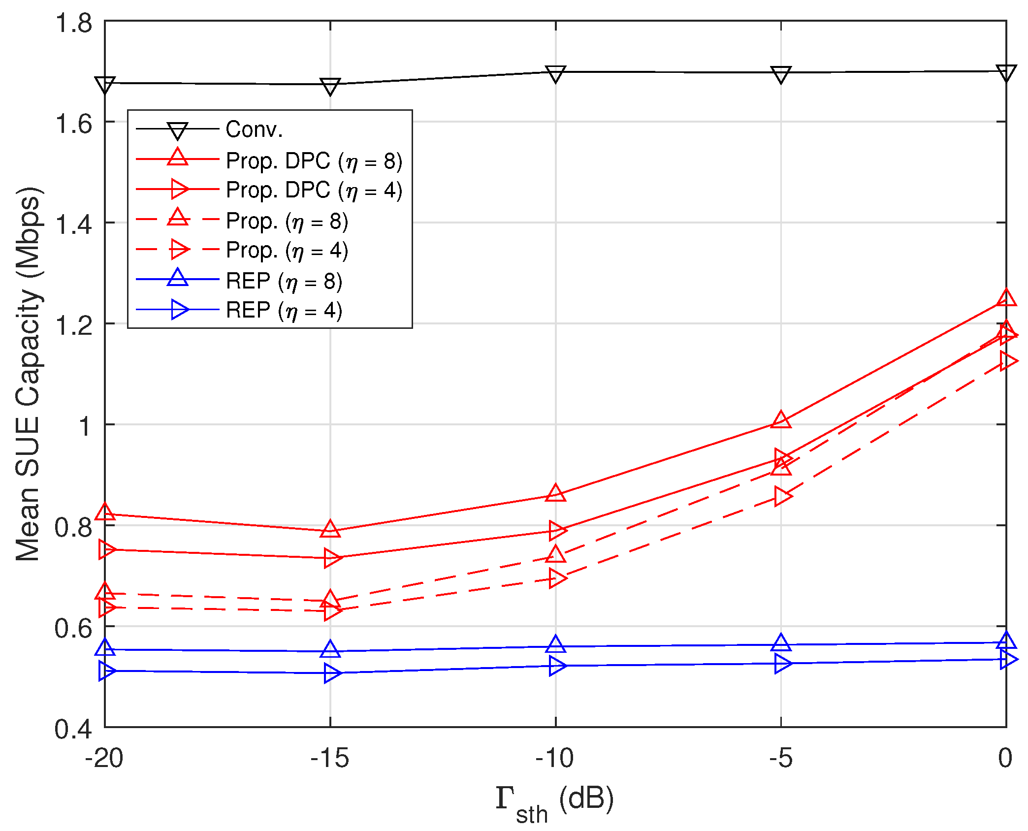
Figure 8 shows the results of the mean SUE capacity (including CUEs) as the value of Γ s t h increases. The results of the conventional scheme are the highest because SBSs only assign subchannels to their SUEs without considering CUEs. On the other hand, the results of other schemes are lower than the conventional scheme because SBSs assign subchannels to their SUEs and CUEs but CUEs are located in the outer zone with low SINRs in general. Even though the power control is applied, the results of the REP schemes are almost the same regardless of Γ s t h . The results of the proposed DPC scheme increase as Γ s t h increases since the proposed DPC scheme appropriately assigns subchannels with consideration of interference from MBSs and allocates the transmission power for SUEs and CUEs in the inner and outer zones. As a result, the results of the proposed DPC scheme (Prop. DPC) with η = 8 dB are 43% and 119% higher than the REP schemes when Γ s t h = −15 and 0 dB, respectively. In addition, the result of the proposed DPC scheme (Prop. DPC) with η = 4 dB is also 21% and 109% higher than the REP schemes when Γ s t h = −20 and 0 dB, respectively.
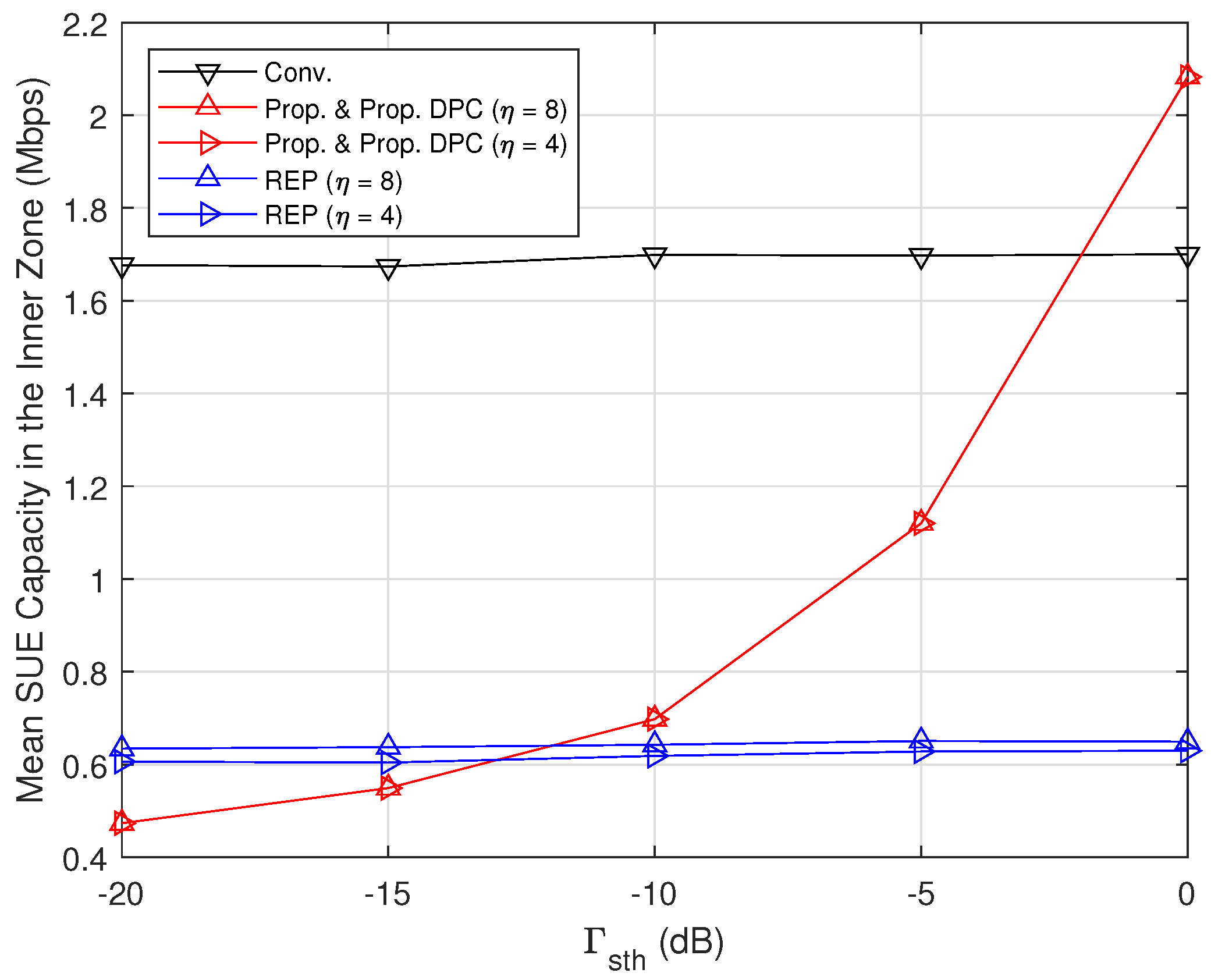
Figure 9 shows the results of the mean SUE capacity in the inner zone as the value of Γ s t h increases. The results of the proposed DPC scheme with η = 4 and 8 dB are the same and increase as Γ s t h increases while those of other schemes are almost the same regardless of Γ s t h . The results of the proposed DPC scheme are lower than those of the REP schemes when Γ s t h < −10 dB but those are higher than the conventional scheme when Γ s t h = 0 dB. That is, the results of the proposed DPC scheme increase since the number of SUEs and CUEs in the inner zone decreases as Γ s t h increases and SBSs assign the same subchannels assigned to MBSs to SUEs and CUEs. As a result, the results of the proposed DPC scheme are 9% and 221% higher than those of the REP schemes when Γ s t h = −10 dB and 0 dB, respectively.
Figure 10 shows the results of the mean SUE capacity in the outer zone as the value of Γ s t h increases. The results of the proposed DPC scheme decrease as Γ s t h increases while those of other schemes are almost the same regardless of Γ s t h . It is shown that the DPC in step 2 of the proposed DPC scheme increases the performance of SUEs and CUEs since the results of the proposed DPC scheme with DPC (Prop. DPC) are always higher than those of the proposed DPC scheme (Prop.). In addition, the results of the proposed DPC scheme are always higher than those of the REP schemes but are lower than those of the conventional scheme except the proposed scheme with DPC (Prop. DPC) with η = 8 dB when Γ s t h = −20 dB. As a result, the results of the proposed DPC scheme with DPC (Prop. DPC) with η = 8 dB are 647% and 227% higher than those of the REP schemes with η = 8 dB when Γ s t h = −20 dB and 0 dB, respectively.
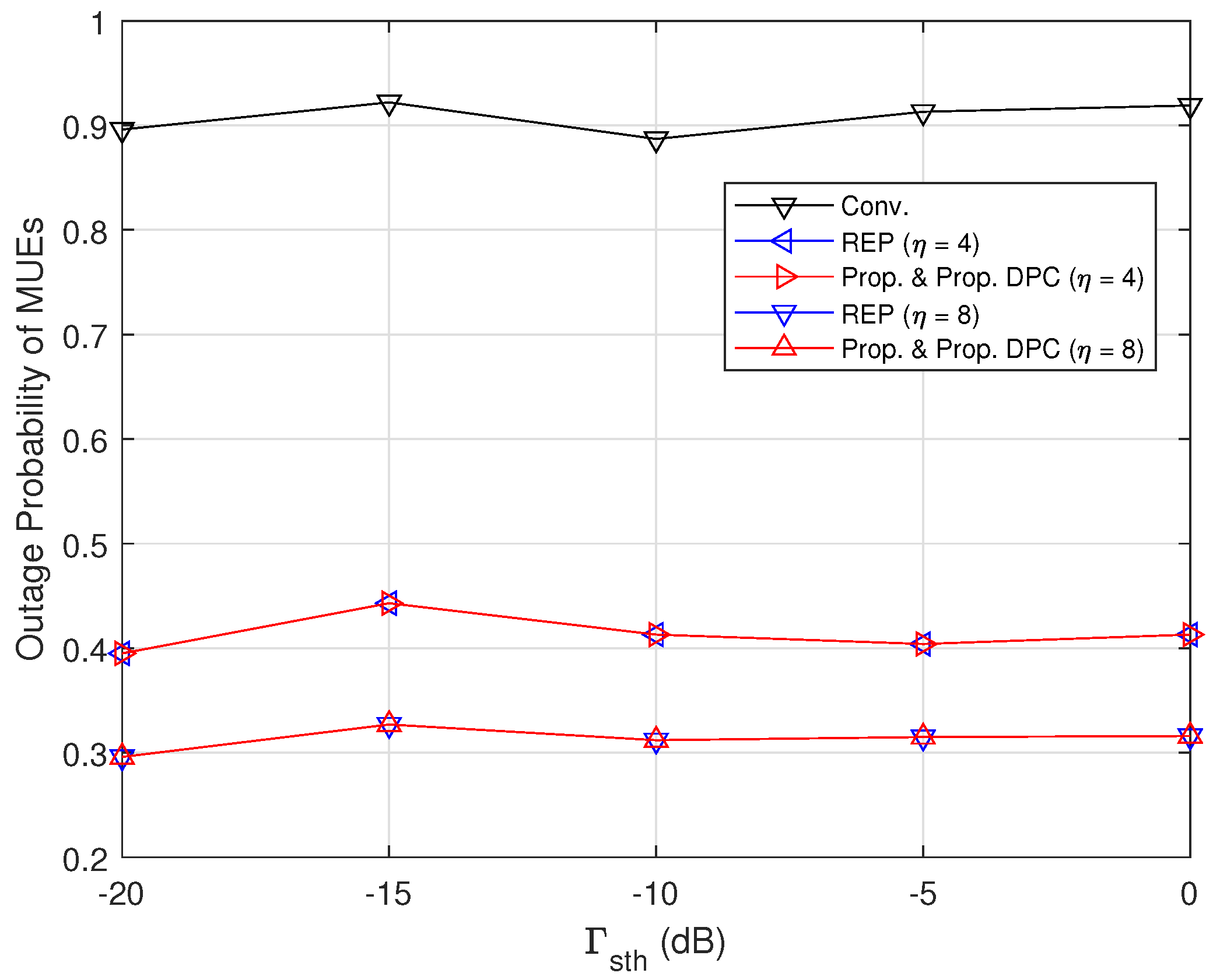
Figure 11 shows the outage probability of MUEs as Γ s t h increases. The results of the conventional scheme are the worst performance due to the significant interference from neighboring SBSs. The results of the proposed DPC scheme are the same as those of the REP scheme since MUEs have no effect on Γ s t h . As a result, the results of the proposed DPC and REP schemes are reduced by 123% and 191% compared to those of the conventional scheme when η = 4 dB and 8 dB, respectively.
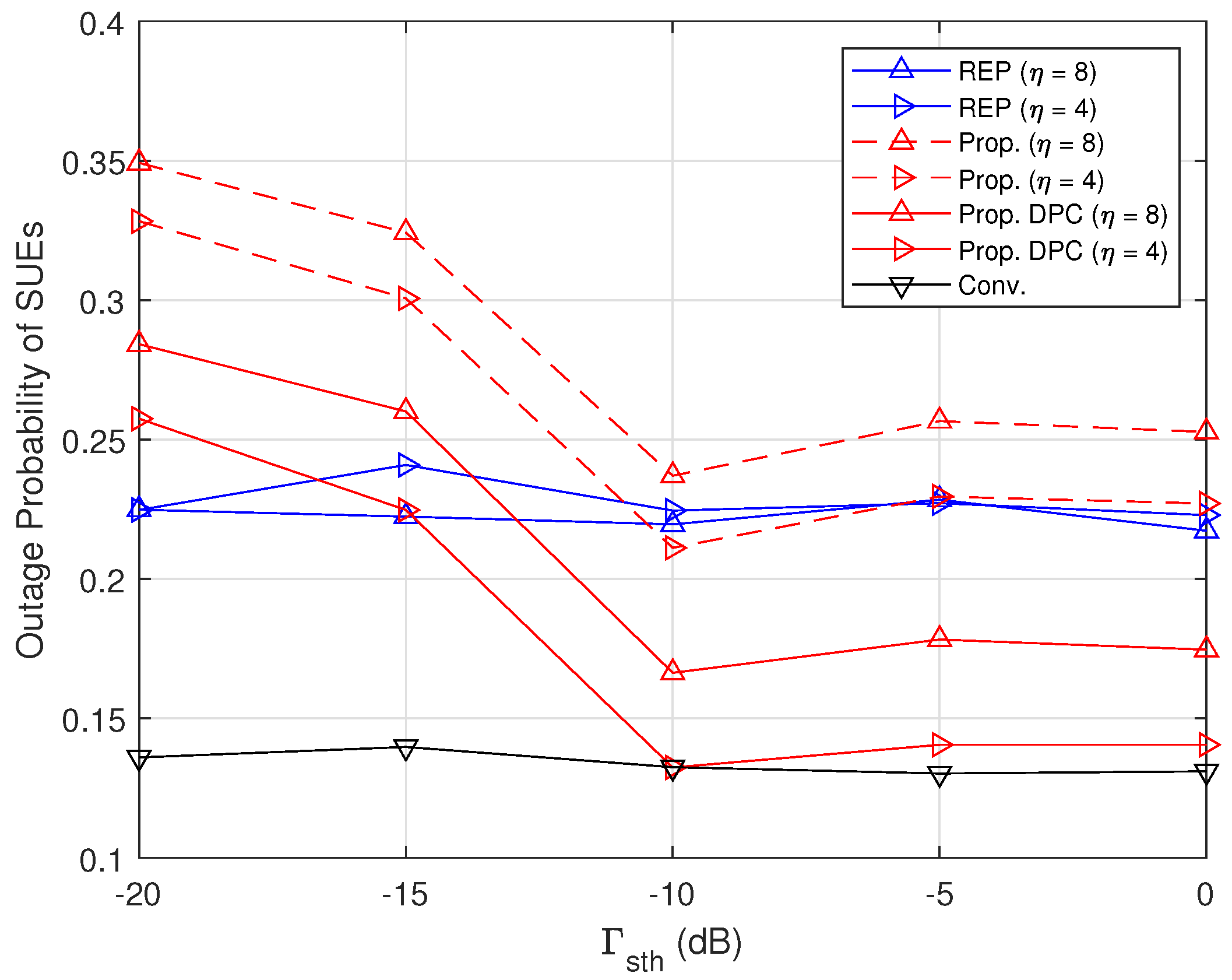
Figure 12 shows the outage probability of SUEs (including CUEs) as Γ s t h increases. The results of the conventional scheme are the lowest performance because SBSs have no CUEs with low SINRs. The results of the REP scheme are almost the same regardless of Γ s t h and higher than those of the conventional scheme. The results of the proposed DPC scheme decrease as Γ s t h increases. The results of the proposed DPC scheme with DPC (Prop. DPC) are higher than those of the REP scheme when Γ s t h < −10 dB because the number of SUEs and CUEs in the outer zone is high. On the other hand, the results of the proposed DPC scheme (Prop. DPC) are lower than those of the REP scheme when Γ s t h −10 dB. In addition, the results of the proposed DPC scheme (Prop. DPC) with η = 4 dB are close to those of the conventional scheme when Γ s t h −10 dB since SBSs allocate the appropriate transmission power for SUEs and CUEs. As a result, the results of the proposed DPC scheme are reduced by 66% and 32% compared to those of the REP scheme when η = 4 dB and 8 dB, respectively.

5. Conclusions

In this paper, we proposed an intelligent DPC scheme with CRE to increase the performance of both SUEs and CUEs for the DL of 5G HetNets. In the proposed DPC scheme, MBSs first found some MUEs that have serious interference from neighboring SBSs and then offloaded them to SBSs to reduce the load of MBSs. In addition, SBSs divided their SUEs and CUEs into two groups, i.e., inner and outer groups, to assign different subchannels and dynamically allocate the appropriate transmission power to increase the performance of both SUEs and CUEs. Through simulation results, it is shown that the proposed DPC scheme increased the mean capacities of SUEs and CUEs by up to 119% with the same performance of the mean MUE capacity and reduced the outage probability of MUEs and SUEs by 191% and 32%, respectively, compared to other DPC schemes with CRE. As a result, the proposed DPC scheme reduced the load of MBSs using CRE and increased the capacity of SUEs and CUEs using the power control of SBSs. We think that the proposed DPC scheme with CRE can be used in 5G advanced and 6G systems if the HetNet is introduced. For future work, we plan to extend the proposed DPC scheme using reinforcement learning to improve the system performance of 5G HetNets.

Author Contributions

Conceptualization, I.B. and S.-J.K.; methodology, I.B. and S.-J.K.; software, I.B.; validation, I.B. and S.-J.K.; formal analysis, I.B. and S.-J.K.; investigation, I.B. and S.-J.K.; resources, I.B. and S.-J.K.; data curation, I.B.; writing—original draft preparation, I.B.; writing—review and editing, S.-J.K.; visualization, I.B. and S.-J.K.; supervision, S.-J.K.; project administration, S.-J.K.; funding acquisition, S.-J.K. All authors have read and agreed to the published version of the manuscript.

Funding

This study was supported by research fund from Chosun University, 2022.

Data Availability Statement

The original contributions presented in the study are included in the article, further inquiries can be directed to the corresponding author.

Conflicts of Interest

The authors declare no conflicts of interest.

References

  1. White Paper. Cisco Annual Internet Report-Cisco Annual Internet Report (2018–2023). Available online: https://www.cisco.com/c/en/us/solutions/collateral/executive-perspectives/annual-internet-report/white-paper-c11-741490.pdf (accessed on 2 March 2023).
  2. Ahmed, S.F.; Alam, M.S.B.; Afrin, S.; Rafa, S.J.; Taher, S.B.; Kabir, M.; Muyeen, S.M.; Gandomi, A.H. Toward a Secure 5G-Enabled Internet of Things: A Survey on Requirements, Privacy, Security, Challenges, and Opportunities. IEEE Access 2024, 12, 13125–13145. [Google Scholar] [CrossRef]
  3. Vaezi, M.; Azari, A.; Khosravirad, S.R.; Shirvanimoghaddam, M.; Azari, M.M.; Chasaki, D.; Popovski, P. Cellular, Wide-Area, and Non-Terrestrial IoT: A Survey on 5G Advances and the Road Toward 6G. IEEE Commun. Surv. Tutor. 2022, 24, 1117–1174. [Google Scholar] [CrossRef]
  4. Agarwal, B.; Togou, M.A.; Marco, M.; Muntean, G. A Comprehensive Survey on Radio Resource Management in 5G HetNets: Current Solutions, Future Trends and Open Issues. IEEE Commun. Surv. Tutor. 2022, 24, 2495–2534. [Google Scholar] [CrossRef]
  5. Sharma, S.; Wang, X. Toward massive machine type communications in ultra-dense cellular IoT networks: Current issues and machine learning-assisted solutions. IEEE Commun. Surv. Tutor. 2020, 22, 426–471. [Google Scholar] [CrossRef]
  6. Small Cell Forum, Release 7.0. Capacity Planning for HetNets. 2016. Available online: https://scf.io/en/documents/174_-_Capacity_planning_for_HetNets.php (accessed on 2 March 2023).
  7. Kim, S.-J. Dynamic channel assignment with consideration of interference and fairness for dense small-cell networks. IEICE Trans. Fundam. Electron. Commun. Comp. Sci. 2018, 101, 1984–1987. [Google Scholar] [CrossRef]
  8. Kim, S.-J.; Bae, S.-H. Interference-aware dynamic channel assignment scheme for enterprise small-cell networks. IEICE Trans. Commun. 2018, E101-B, 2453–2461. [Google Scholar] [CrossRef]
  9. Kamel, M.; Hamouda, W.; Youssef, A. Ultra-dense networks: A survey. IEEE Commun. Surv. Tutor. 2016, 18, 2522–2545. [Google Scholar] [CrossRef]
  10. Teng, Y.; Liu, M.; Yu, F.R.; Leung, V.C.; Song, M.; Zhang, Y. Resource Allocation for Ultra-Dense Networks: A Survey, Some Research Issues and Challenges. IEEE Commun. Surv. Tutor. 2019, 21, 2134–2168. [Google Scholar] [CrossRef]
  11. Damnjanovic, A.; Montojo, J.; Wei, Y.; Ji, T.; Luo, T.; Vajapeyam, M.; Yoo, T.; Song, O.; Malladi, D. A survey on 3GPP heterogeneous networks. IEEE Wirel. 2011, 18, 10–21. [Google Scholar] [CrossRef]
  12. Gupta, A.; Jha, R.K. A Survey of 5G Network: Architecture and Emerging Technologies. IEEE Access 2015, 3, 1206–1232. [Google Scholar] [CrossRef]
  13. Lai, W.K.; Liu, J.K. Cell Selection and Resource Allocation in LTE-Advanced Heterogeneous Networks. IEEE Access 2018, 6, 72978–72991. [Google Scholar] [CrossRef]
  14. Abbas, Z.H.; Muhammad, F.; Jiao, L. Analysis of Load Balancing and Interference Management in Heterogeneous Cellular Networks. IEEE Access 2017, 5, 14690–14705. [Google Scholar] [CrossRef]
  15. Park, J.B.; Kim, K.S. Load-Balancing Scheme with Small-Cell Cooperation for Clustered Heterogeneous Cellular Networks. IEEE Trans. Veh. Technol. 2018, 67, 633–649. [Google Scholar] [CrossRef]
  16. Ye, Q.; Rong, B.; Chen, Y.; Al-Shalash, M.; Caramanis, C.; Andrews, J.G. User Association for Load Balancing in Heterogeneous Cellular Networks. IEEE Tran. Wirel. Commun. 2013, 12, 2706–2716. [Google Scholar] [CrossRef]
  17. Peng, M.; Wang, C.; Li, J.; Xiang, H.; Lau, V. Recent Advances in Underlay Heterogeneous Networks: Interference Control, Resource Allocation, and Self-Organization. IEEE Commun. Surv. Tutor. 2015, 17, 700–729. [Google Scholar] [CrossRef]
  18. Xu, Y.; Gui, G.; Gacanin, H.; Adachi, F. A Survey on Resource Allocation for 5G Heterogeneous Networks: Current Research, Future Trends, and Challenges. IEEE Commun. Surv. Tutor. 2021, 23, 668–695. [Google Scholar] [CrossRef]
  19. Hu, H.; Zhang, B.; Hong, Q.; Chu, X.; Zhang, J. Coverage Analysis of Reduced Power Subframes Applied in Heterogeneous Networks With Subframe Misalignment Interference. IEEE Wirel. Commun. Lett. 2018, 7, 752–755. [Google Scholar] [CrossRef]
  20. Ding, M.; López-Pérez, D.; Xue, R.; Vasilakos, A.V.; Chen, W. On Dynamic Time-Division-Duplex Transmissions for Small-Cell Networks. IEEE Trans. Veh. Technol. 2016, 65, 8933–8951. [Google Scholar] [CrossRef]
  21. Hu, H.; Weng, J.; Zhang, J. Coverage Performance Analysis of FeICIC Low-Power Subframes. IEEE Trans. Wirel. Commun. 2016, 15, 5603–5614. [Google Scholar] [CrossRef]
  22. Zhang, Y.; Cui, Z.; Cui, Q.; Yu, X.; Liu, Y.; Xie, W.; Zhao, Y. Energy Efficiency Analysis of Heterogeneous Cellular Networks With Extra Cell Range Expansion. IEEE Access 2017, 5, 11003–11014. [Google Scholar] [CrossRef]
  23. Singh, R.; Murthy, C.S.R. Techniques for Interference Mitigation Using Cooperative Resource Partitioning in Multitier LTE HetNets. IEEE Syst. J. 2018, 12, 843–853. [Google Scholar] [CrossRef]
  24. Gopalam, S.; Hanly, S.V.; Whiting, P. Distributed User Association and Resource Allocation Algorithms for Three Tier HetNets. IEEE Trans. Wirel. Commun. 2020, 19, 7913–7926. [Google Scholar] [CrossRef]
  25. Dhungana, Y.; Tellambura, C. Multichannel Analysis of Cell Range Expansion and Resource Partitioning in Two-Tier Heterogeneous Cellular Networks. IEEE Trans. Wirel. Commun. 2016, 15, 2394–2406. [Google Scholar] [CrossRef]
  26. Liu, C.; Li, M.; Hanly, S.V.; Whiting, P. Joint Downlink User Association and Interference Management in Two-Tier HetNets With Dynamic Resource Partitioning. IEEE Trans. Veh. Technol. 2017, 66, 1365–1378. [Google Scholar] [CrossRef]
  27. Zhao, Y.; Xia, H.; Zeng, Z.; Wu, S. Joint Clustering-based Resource Allocation and Power Control in Dense Small Cell Networks. In Proceedings of the IEEE/CIC International Conference on Communications in China (ICCC), Shenzhen, China, 2–4 November 2015; pp. 1–5. [Google Scholar] [CrossRef]
  28. Daeinabi, A.; Sandrasegaran, K.; Zhu, X. Performance Evaluation of Cell Selection Techniques for Picocells in LTE-Advanced Networks. In Proceedings of the 10th International Conference on Electrical Engineering/Electronics, Computer, Telecommunications and Information Technology, Krabi, Thailand, 15–17 May 2013; pp. 1–6. [Google Scholar] [CrossRef]
  29. Kshatriya, S.N.S.; Yerrapareddy, S.R.; Akhtar, N.; Milleth, J.K. A Novel Power Control Scheme for Macro-Pico Heterogeneous Networks with Biased Association. In Proceedings of the IEEE International Conference on Communications Workshops (ICC), Budapest, Hungary, 9–13 June 2013; pp. 1117–1122. [Google Scholar] [CrossRef]
  30. Sun, Y.; Wang, Z.; Fang, Y.; Wu, Y. Resource management with multilevel interference mitigation in Heterogeneous Network. In Proceedings of the International Wireless Communications and Mobile Computing Conference (IWCMC), Nicosia, Cyprus, 4–8 August 2014; pp. 1183–1187. [Google Scholar] [CrossRef]
  31. Zhou, H.; Xia, H.; Guo, C.; Wu, Y. Energy-Efficient Time-Power Domain Resources Allocation for Macro-Pico Heterogeneous Networks. In Proceedings of the International Symposium on Wireless Personal Multimedia Communications (WPMC), Sydney, NSW, Australia, 7–10 September 2014; pp. 526–530. [Google Scholar] [CrossRef]
  32. Matsuoka, S.; Kikuchi, K.; Otsuka, H. Performance Analysis of Cooperative Control between CSO on CRE and Transmission Power for Pico-eNB in HetNet. In Proceedings of the Sixth International Conference on Ubiquitous and Future Networks (ICUFN), Shanghai, China, 8–11 July 2014; pp. 505–506. [Google Scholar] [CrossRef]
  33. Dong, A.; Luo, X.; Du, Q. Dynamic power control of pico base stations in cooperation clusters towards amorphous coverage. In Proceedings of the International Conference on Information and Communications Technologies (ICT 2015), Xi’an, China, 24–26 April 2015; pp. 1–8. [Google Scholar] [CrossRef]
  34. Gong, Y.; Gu, X.; Zhao, X.; Li, W.; Zhang, L. Adaptive Frequency-domain Interference Coordination Combined with CRE in Heterogeneous Network. In Proceedings of the IEEE 16th International Conference on Communication Technology (ICCT), Hangzhou, China, 18–20 October 2015; pp. 719–724. [Google Scholar] [CrossRef]
  35. Zhao, Y.; Xia, H.; Zeng, Z.; Liu, F.; Han, R.; Du, C. Joint Resource Block Assignment and Power Control In Macro-Pico Heterogeneous Networks. In Proceedings of the 15th IEEE International Conference on Communication Technology, Guilin, China, 17–19 November 2013; pp. 286–921. [Google Scholar] [CrossRef]
  36. Jo, Y.; Kim, H.; Lim, J.; Hong, D. Self-Optimization of Coverage and System Throughput in 5G Heterogeneous Ultra-Dense Networks. IEEE Wirel. Commun. Lett. 2020, 9, 285–288. [Google Scholar] [CrossRef]
  37. Liu, D.; Wang, L.; Chen, Y.; Elkashlan, M.; Wong, K.K.; Schober, R.; Hanzo, L. User Association in 5G Networks: A Survey and an Outlook. IEEE Commun. Surv. Tutor. 2016, 18, 1018–1044. [Google Scholar] [CrossRef]
  38. Shaddad, R.Q.; Alsarori, N.A.; Alzylai, M.O.; Shami, T.M. Biased User Association in 5G Heterogeneous Networks. In Proceedings of the 2021 International Conference of Technology, Science and Administration, Taiz, China, 1–4 March 2021; pp. 286–921. [Google Scholar] [CrossRef]
  39. Yoo, H.; Moon, J.; Na, J.; Hong, E. User Association and Load Balancing Based on Monte Carlo Tree Search. IEEE Access 2023, 11, 126087–126097. [Google Scholar] [CrossRef]
  40. 3rd Generation Partnership Project (3GPP). TR 36.814 V9.0.0 [2009-05], Further Advancements for E-UTRA Physical Layer Aspects. Available online: https://www.3gpp.org/ftp/Specs/archive/36_series/36.814/36814-900.zip (accessed on 18 September 2023).
  41. 3rd Generation Partnership Project (3GPP). R4-092042 [2009-05], Simulation Assumptions and Parameters for FDD HeNB RF Requirements. Available online: https://www.3gpp.org/ftp/tsg_ran/WG4_Radio/TSGR4_51/Documents/R4-092042.zip (accessed on 2 March 2023).
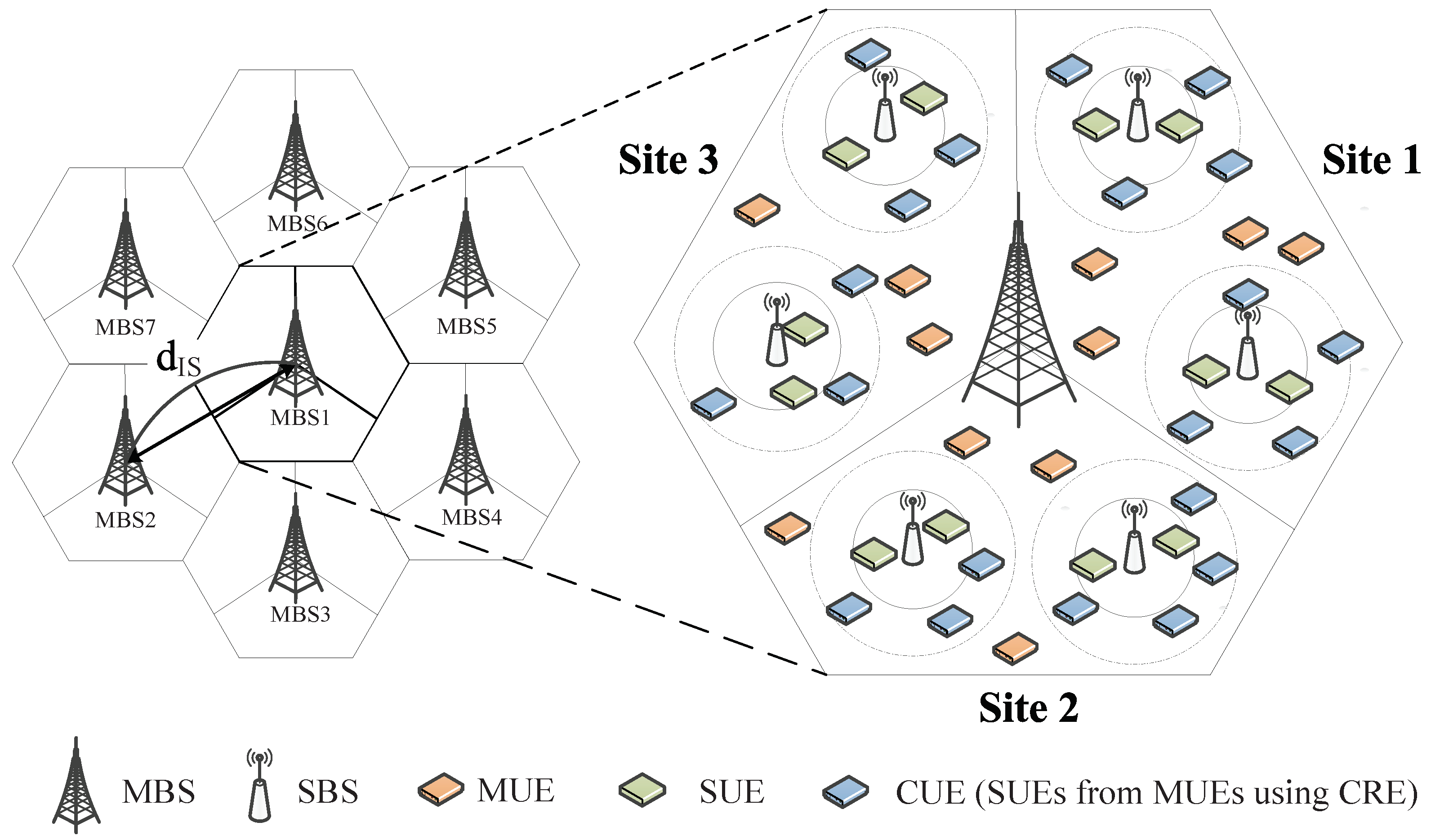
Figure 1. System architecture of 5G HetNets.
Applsci 14 03789 g001
Figure 2. Channel assignments for MBSs and SBSs in 5G HetNets (MBSs assign subchannel group A, B, and C to MUEs in site 1, 2, and 3, respectively, while each SBS assigns total subchannels to its SUEs and CUEs).
Applsci 14 03789 g002
Figure 3. An example of the CRE operation in 5G HetNets.
Applsci 14 03789 g003
Figure 4. Comparison of the transmission power operation for conventional (no power control), REP, and proposed DPC schemes (in the proposed DPC scheme, SBSs of site 1 assign subchannel group A with power contorl to each of SUEs and CUEs in the inner zone, and assign subchannel group B and C to SUEs and CUEs in the outer zone).
Applsci 14 03789 g004
Figure 5. Distribution of MUEs and CUEs based on Γ s t h and η .
Applsci 14 03789 g005
Figure 6. Distribution of SUEs and CUEs in SBS as Γ s t h .
Applsci 14 03789 g006
Figure 7. Mean MUE capacity vs. Γ s t h .
Applsci 14 03789 g007
Figure 8. Mean SUE capacity (including CUEs) vs. Γ s t h .
Applsci 14 03789 g008
Figure 9. Mean SUE capacity in the inner zone vs. Γ s t h .
Applsci 14 03789 g009
Figure 10. Mean SUE capacity in the outer zone vs. Γ s t h .
Applsci 14 03789 g010
Figure 11. Outage probability of MUEs vs. Γ s t h .
Applsci 14 03789 g011
Figure 12. Outage probability of SUEs vs. Γ s t h .
Applsci 14 03789 g012
Table 1. Summary of related work.
ReferenceDuplex
Mode
Almost Blank Subframe
(ABS)
Split
Subchannels
Power
Control
Power Control Devices
(Active)
Target Devices
(Passive)
 [27]TDDDynamicMBSCUE
 [28]TDDn/aStaticMBSCUE
 [29]TDDn/aDynamicMBS, SBSCUE
 [30]TDDn/aDynamicMBSCUE
 [31]TDDn/aDynamicSBSCUE
 [32]FDDn/an/aStaticSBSCUE
 [33]FDDn/aDynamicSBSCUE
 [34]FDDn/aDynamicMBSCUE
 [35]FDDn/aDynamicMBSCUE
 [36]FDDn/aDynamicSBSCUE
ProposedFDDn/aDynamicSBSCUE, SUE
Table 2. List of main symbols and notations.
NotationsDescriptions
M Set of macro base stations (MBSs)
S Set of small-cell base stations (SBSs)
N Set of macro user equipments (MUEs)
T Set of small-cell user equipments (SUEs)
K Set of total subchannels
γ m n k SINR of MUE n serviced by MBS m at subchnnel k
γ m s t k SINR of SUE t serviced by SBS s in the coverage of MBS m at subchnnel k
h m n Channel gain between MBS m and MUE n
h m s t Channel gain between SBS s and SUE t in the coverage of MBS m
P M B S Transmission power of MBSs
P S B S Transmission power of SBSs
p m a x S B S Maximum transmission power of SBSs
ξ m n M B S RSRP between MBS m and MUE n
ξ m s n S B S RSRP between SBS s and SUE t in the coverage of MBS m
L m n Path loss between MBS m and MUE n
L m s t Path loss between SBS s and SUE t in the coverage of MBS m
ψ m n k Indicator variable to assign subchannel k from MBS m to MUE n
ψ m s t k Indicator variable to assign subchannel k from SBS s of MBS m to SUE t
C m n Capacity of MUE n served by MBS m
C m s t Capacity of SUE t served by SBS s in the coverage of MBS m
P o u t M U E Outage probability of MUEs
P o u t S U E Outage probability of SUEs (including CUEs)
Γ t h Given target SINR threshold for outage probability
Γ s t h Given target SINR threshold for SUEs in the inner and outer zones
WBandwidth per subchannel
η Given CRE bias for SBSs
d I S Inter-site distance between MBSs
A ( θ ) Antenna gain of MBSs
A m g Maximum antenna gain of MBSs
A m a Maximum attenuation of MBSs
σ 2 White noise power
Table 3. System parameters.
ParameterValue
Cellular layoutHexagonal grid, 3 sectors per cell
Carrier Frequency2 GHz
Bandwith10 MHz
Traffic modelFull buffer (continuous traffic)
Number of RBs50
Inter site distance ( d I S )500 m [40]
SBS radius40 m
Number of MBSs (M)7
Number of SBSs per cell site (S)4
Number of MUEs per cell site (N)30
Number of SUEs per SBS (T)10
Total transmission power of MBSs46 dBm  [41]
Total transmission power of SBSs30∼37 dBm  [41]
Path loss from MBSs to MUEs 128.1 + 37.6 log 10 d dB [41]
Path loss from SBSs to SUEs 140.7 + 37.6 log 10 d dB [41]
Minimum distance between MBSs and SBSs75 m [41]
Minimum distance between SBSs and SBSs40 m [41]
Minimum distance between MBSs and MUEs35 m [41]
Minimum distance between SBSs and SUEs10 m [41]
Given threshold of SUEs ( Γ s t h )−20 ∼ 0 dB
Given target threshold ( Γ t h )−10 dB
Given CRE bais ( η )4, 8 dB
Power control value for the REP scheme ( α ) 0.20  [35]
A m g and A m a 14 dB, 20 dB [41]
Terminal noise level ( σ 2 )−174 dBm/Hz
Disclaimer/Publisher’s Note: The statements, opinions and data contained in all publications are solely those of the individual author(s) and contributor(s) and not of MDPI and/or the editor(s). MDPI and/or the editor(s) disclaim responsibility for any injury to people or property resulting from any ideas, methods, instructions or products referred to in the content.