Abstract
Reducing the tonal noise from airfoil instabilities has attracted significant interest from the aeronautical community in the past few years. The aim of this paper is to investigate the effect of structured porous trailing edges on the tonal noise reduction performance of a symmetrical NACA 0012 airfoil. Detailed parametric testing was performed in an open-jet wind tunnel between the baseline solid trailing edge and seventeen structured porous trailing edges with different sub-millimeter-scale pores. The experimental results demonstrate that structured porous trailing edges can reduce the noticeable tonal noise of the symmetrical NACA 0012 airfoil. Moreover, the design parameters for the structured porous edges have slightly different impacts on the tonal noise reduction performance between a zero angle of attack (α = 0°) and a non-zero angle of attack (α = 10°): better airfoil tonal noise reduction is due to the porous parameters of small pore coverage, small-to-moderate chordwise spacing, and moderate spanwise spacing at α = 0°. On the other hand, the optimal combination of the structured porous edge at α = 10° is the configuration with larger pore coverage, smaller chordwise spacing, and spanwise spacing.
1. Introduction
The reduction in an airfoil’s self-noise level is one of the practical advantages of reducing the community noise impact of airports that are close to densely populated residential areas. Tonal noise from instabilities is an important airfoil self-noise mechanism at the trailing edge [1,2,3], especially on airfoils operating at low-to-moderate Reynolds numbers and angles of attack, e.g., small, unmanned air vehicles. To reduce the tonal noise from instabilities, a number of bio-inspired aerodynamic noise control techniques have been investigated in the past few decades [4], which can be classified into trailing edge serrations, brush-type extensions, and porous edges.
Chong et al. [5,6,7] investigated the capability of trailing edge serrations in reducing noise from airfoil instabilities. They found that trailing edge serrations could alter the length of the laminar separation bubble and inhibit the formation of a separated boundary layer at the pressure surface of the airfoil’s trailing edge, which in turn reduces the amplitude of the tonal noise from the instability. Time-resolved PIV (Particle Image Velocimetry) measurements of instantaneous flow evolution by Serpieri et al. [8] confirmed another noise reduction mechanism of serrated trailing edges, as the authors observed that they could strongly reduce the coherence of the shed Tollmien–Schlichting waves as they advected past the airfoil trailing edge. Herr and Dobrzynski [9,10] demonstrated that brush-type extensions could reduce both the broadband noise from a turbulent boundary layer and quasi-tonal vortex shedding noise if the edge modifications exceeded the minimum fiber length and had small fiber spacing. More recently, Wang et al. [11,12] conducted detailed aeroacoustic measurements on a set of porous edges, which were made of open-cell metallic foams with a piecewise gradient-distributed property in terms of pores per inch (ppi). They showed that the gradient-distributed porous edges could noticeably reduce the tonal noise from airfoil instabilities, and the performance was enhanced when the porous edges could gradually sparsely transition from the solid main body to that of the downstream air flow. Jiang et al. [13] numerically captured the noise reduction and increase caused by a micro-tube porous trailing edge and its effect on the wavenumber–frequency spectrum. An in-depth analysis of the dynamic structures of the trailing edge flow and surface pressure fields linked the noise reduction to ‘cross-jet-like’ flow permeation through the micro-tube structures.
With the development of 3D printing technology (in terms of further meeting airworthiness requirements, such as maintainability, strength, and costs) and for the convenience of measuring the internal flow field of the pores, there is a tendency to replace traditional metal foam or polyurethane porous materials, which typically possess a randomized internal structure, with customized structured porous designs. Arcondoulis et al. [14] validated that a 3D-printed porous coated cylinder can be used as a passive noise control method to reduce the cylinder vortex’s shedding tone. Carpio et al. [15] demonstrated that an asymptotic value of up to 9.3 dB of broadband noise attenuation from the turbulent boundary layer was obtained by using 3D-printed perforated trailing edge inserts for increasing the flow permeability. They also reported that an extremely loud shedding-related tonal noise is generated from the blunt solid–permeable junction section, so it is recommended to optimize the physical parameters of the structured porous inserts to achieve better broadband noise abatement. Zhang and Chong found that the most optimized 3D-printed porous trailing edge could obtain a maximum turbulent broadband noise reduction of 7 dB at an α = 0° angle of attack [16], and the reduction in the broadband noise was more significant when α ≤ 0° [17]. They also observed an unwanted bluntness-related tonal shedding noise at a high Reynolds number.
However, fewer studies have been reported on reducing the tonal noise from airfoil instabilities using structured porous edges. Zhang and Chong [17] were some of the first to perform such experimental investigations on an asymmetric, highly cambered NACA 65(12)-10 airfoil at an α = 0° angle of attack. They showed that 3D-printed porous trailing edges could suppress the tonal noise from laminar instabilities, especially in the case of a pore diameter d = 1 mm and porosity σ = 30% at a low free-stream velocity of V∞ = 20 m/s. On the other hand, at high velocities of V∞ ≥ 40 m/s, additional bluntness-related tonal peaks appeared to jeopardize the overall noise reduction performance. Since then, as far as the authors know, no detailed parametric study on reducing the tonal noise from airfoil instabilities by using structured porous trailing edges has been presented in the literature, and this study therefore aims to answer the following questions: (1) Can structured porous trailing edges reduce the tonal noise of a symmetrical airfoil, such as a NACA 0012 airfoil? (2) How do the pore diameter, pore coverage, pore position, and pore arrangement order affect tonal noise reduction? (3) How do the chordwise spacing and spanwise spacing between adjacent pores affect tonal noise reduction? (4) Can structured porous trailing edges still suppress tonal noise at a non-zero angle of attack, and is there any difference from a zero angle of attack? These motivate the present paper, which aims to fill this knowledge gap. Detailed experimental measurements in an open-jet wind tunnel were performed on a set of NACA 0012 airfoils with different sub-millimeter-scale porous settings. Experimental results revealed that a noticeable tonal noise reduction can be obtained for the symmetrical NACA 0012 airfoil. Moreover, design parameters for structured porous edges, such as pore position and pore coverage, affect noise reduction performance, and the influence is different between a zero angle of attack and a non-zero angle of attack. These experimental results will be used to guide parameter designs in numerical methods (e.g., using a large eddy simulation and the Ffowcs Williams–Hawkings acoustic analogy) to reveal the underlying noise reduction mechanisms, which is part of our future work and will be presented in other papers.
The remainder of the paper is organized as follows: Section 2 reviews the experimental setup and data processing in detail. In Section 3, the noise measurement results of the different experiments are presented and discussed. Finally, Section 4 concludes the findings of the present experimental study.
2. Experimental Setup and Data Processing
2.1. Experimental Setup
Noise measurements were conducted in an aeroacoustic open-jet wind tunnel (see Figure 1), which is situated in a 5.5 m × 3.7 m × 4.0 m anechoic chamber. The nozzle exit of this wind tunnel is rectangular, with dimensions of 0.55 m (width) × 0.4 m (height). This tunnel has a turbulence intensity of less than 0.2% and a maximum free-stream velocity of 100 m/s for the open test section.
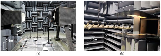
Figure 1.
The 0.55 m × 0.4 m open-jet wind tunnel (a) without the tested model and (b) with the tested model.
The investigated airfoil model is a symmetrical 2D NACA 0012 airfoil, with a nominal spanwise length L = 398 mm and a nominal chordwise length c = 200 mm. The rear end of the airfoil has a thickness of 0.5 mm, to avoid significant vortex shedding tonal noise of a blunt airfoil trailing edge. The NACA 0012 airfoil is held by two parallel side plates, which are used to avoid the effect of tip vortex shedding noise and to adjust the geometric angle of attack of the model. For this investigation, experiments were performed at three geometric angles of attack of α = 0°, α = 5°, and α = 10°, and seven free-stream velocities from V∞ = 10 m/s to V∞ = 70 m/s (interval of 10 m/s), corresponding to chord-based Reynolds numbers Rec ranging between 1.3 × 10⁵ and 9.3 × 10⁵.
As depicted in Figure 2, the model contains an interchangeable trailing edge section on the aluminum main body. The nominal chordwise length of this interchangeable section is 30 mm. In order to cover structured pores, it is further divided into three subregions (denoted as L, M, and N, from upstream to downstream, respectively) with an equal nominal chordwise length of 10 mm. As reported by Zhang and Chong [16] in their experimental investigation of turbulent broadband noise reduction by using 3D-printed porous trailing edges, pore diameter is the first-order parameter for acoustical responses, and typically, a pore diameter larger than 1 mm will generate more unwanted shedding-related tones, which may jeopardize the noise reduction performance. Therefore, sub-millimeter-scale pores are investigated in the present study. As the pore diameter is very small, to ensure the effectiveness of the structured pores, we first used 3D printing technology and multi-axis CNC (Computer Numerical Control) forming technology to produce several small test pieces, respectively. As shown in Figure 3a, 3D-printed pores are not perfectly round (similar phenomena were observed by Carpio et al. [15]) and may even be blocked, especially when the pore depth is large and the pore size is small (due to the limitations of 3D printing and the impact of its cooling process). On the other hand, pores with a diameter of 0.6 mm manufactured via CNC in Figure 3b are satisfactory. Moreover, CNC-manufactured porous surfaces can provide sufficient structural strength for future technical applications in a full-scale wing. Therefore, one solid baseline trailing edge and seventeen structured porous trailing edges (see Table 1) are finally manufactured by using mechanical processing technology.
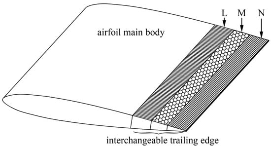
Figure 2.
Schematic of the tested model (not to scale).
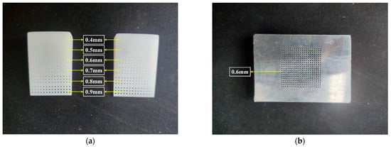
Figure 3.
Test pieces of the structured pores: (a) 3D-printed and (b) CNC-processed.

Table 1.
Structured porous trailing edges with different pore parameters.
Several studies [11,12,15,16,17] have shown that the pore diameter, pore coverage, pore position, and pore arrangement order have a significant impact on airfoil self-noise reduction. Thus, the pore design of this experimental process is depicted in Figure 4, and it is controlled by pore diameter dh, chordwise spacing ch, and spanwise spacing sh between adjacent pores. Unless otherwise specified, the investigated porous trailing edges are configured with dh = 0.6 mm, ch = 2.0 mm, and sh = 10.0 mm. The three subregions of the interchangeable porous trailing edge were covered with the same/different pore diameter, and L**M**N** was used to label each configuration. For example, L04M06N08 in Table 1 corresponds to the configuration whose three subregions are configured by 0.4 mm, 0.6 mm, and 0.8 mm pores, from the upstream to the downstream. L00M06N00 represents a structured porous edge whose middle subregion is covered with 0.6 mm pores, while the remaining two subregions do not have pores.
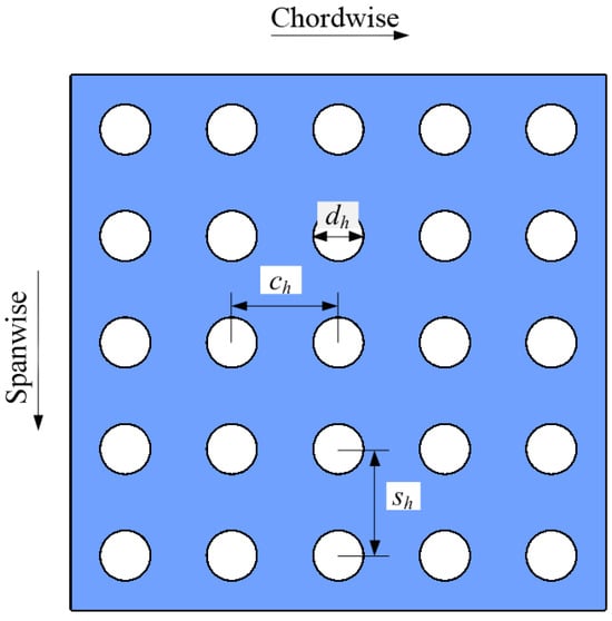
Figure 4.
Pattern of the pore design.
2.2. Data Acquisition and Processing
Detailed acoustic tests are presented in Figure 1b and Figure 5, where nine free-field microphones of type G.R.A.S 46 AE (GRAS Sound and Vibration, Holte, Denmark) were used to collect acoustic data, while only the measured signals perpendicular to the airflow (see Figure 5) are shown in this paper for easier processing. This microphone was positioned out of the airflow, and its head was 1.0 m apart from the rear end of the airfoil at α = 0° in the midspan plane. The acquired data were recorded at a 51.2 kHz sampling rate over 30 s of sampling time. The sound pressure level (SPL) was subsequently calculated using an 8192-point Hanning window function and 50% data overlap. Then, the overall sound pressure level (OASPL) could be computed by integrating the SPL between 100 Hz and 25.6 kHz, where the lower frequency is limited by the cutoff frequency of the anechoic chamber and the upper frequency corresponds to the Nyquist frequency of the measured signal. A free-field correction of different angles of incidence is not performed in this work because the effect is the same for both baseline trailing edges and porous trailing edges, and our analysis is based on the measured noise level differences.
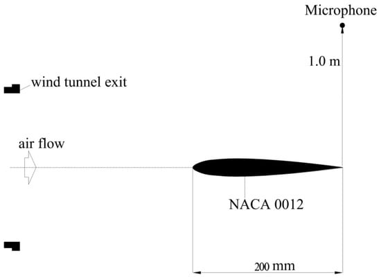
Figure 5.
Sketch of the experimental setup (not to scale).
The difference in sound pressure level (ΔSPL) between a structured porous edge and the baseline nonporous edge is defined in Equation (1):
where SPLp and SPLb are the SPL measured for the porous and baseline edge, respectively.
ΔSPL = SPLp − SPLb,
Similarly, the difference in overall sound pressure level (ΔOASPL) between a structured porous edge and the baseline solid edge is defined in Equation (2):
ΔOASPL = OASPLp − OASPLb.
Both ΔSPL and ΔOASPL can be used to evaluate the acoustic performance of the different structured porous edges, where a negative value represents noise reduction while a positive value indicates noise increase.
3. Discussion of the Noise Results
3.1. Experimental Validation of the Baseline Airfoil
The measured acoustic spectra of the baseline NACA 0012 airfoil with a nonporous solid trailing edge under different free-stream velocities are presented in Figure 6 for geometric angles of attack of α = 0°, α = 5°, and α = 10°.
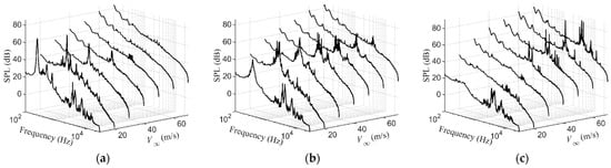
Figure 6.
Acoustic spectra of the baseline NACA 0012 airfoil under different free-stream velocities. (a) α = 0°, (b) α = 5°, and (c) α = 10°.
Using the criterion of Chong et al. [18] that an airfoil tonal noise is detected as the SPL value exceeds the broadband hump by 10 dB or greater, it can be easily observed that the experimental results have several characteristic features similar to data from the literature: Tonal noise is sensitive to changes in the free-stream velocity and the geometric angle of attack. For the NACA 0012 airfoil with a sharp, nonporous trailing edge inclined at α = 0°, tonal noise is only detected at low free-stream velocities from 10 m/s to 40 m/s (see Figure 6a), while tonal noise disappears, and the acoustic spectrum is basically broadband at high free-stream velocities. As the geometric angle of attack increases to α = 5°, tonal noise is detected from the baseline NACA 0012 airfoil for all free-stream velocities. As shown in Figure 6b, the peak SPL of the tonal noise first increases and then decreases with the free-stream velocity at this angle of attack. Through observing Figure 6c for α = 10°, it is seen that the free-stream velocity at which tonal noise begins to appear increases to 40 m/s. It is agreed that a laminar separation area on either the pressure side or the suction side of the airfoil trailing edge is a necessary condition for the generation of strong tonal noise resulting from instability [19,20,21]. Moreover, it is found that the state of the boundary layer flow (laminar or turbulent) close to the airfoil trailing edge is significantly dependent on both model parameters (such as chord length and airfoil camber) and flow parameters (free-stream velocity and angle of attack) [22,23,24]. Therefore, the aforementioned sensitivity of the airfoil tonal noise stems from the complex nature of the laminar separation in the trailing edge boundary layer. Figure 7 summarizes the tonal noise regimes of the baseline NACA 0012 airfoil in this experiment, compared with the predicted tonal envelope of Lowson et al. [25] based on their theoretical methods. It can be seen that the tonal regimes are all in the envelope curve, which indirectly confirms the validity of this experiment and thus supports the subsequent parametric study in the following subsections.
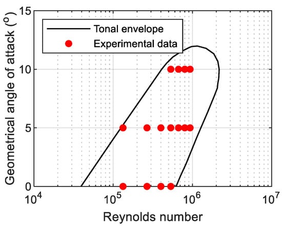
Figure 7.
Tonal noise regimes of the baseline NACA 0012 airfoil.
3.2. Effect of the Pore Diameter
Figure 8 presents ΔSPL as a function of free-stream velocity and frequency for structured porous trailing edges whose three subregions are covered by pores of the same diameter. It can be seen that the structured porous edges can significantly suppress airfoil self-noise, especially in the regimes corresponding to tonal noise. A maximum noise reduction of 28.09 dB and 36.62 dB are obtained for angles of attack of α = 0° and α = 10°, respectively. However, noise increases of up to 22.58 dB and 21.58 dB are observed at α = 0° and α = 10°, respectively. These increases can be divided into two types: Firstly, the increase around the peak frequency of the tonal noise is generally attributed to the frequency shift of the tonal noise. Figure 9 plots typical noise spectra between the structured porous trailing edges and the baseline trailing edge. As seen in these plots, the peak frequency of the tonal noise (see the black circle in Figure 9) at V∞ = 30 m/s and α = 0° shifts from 1256.25 Hz for the baseline trailing edge to 1350 Hz, 1343.75 Hz, and 1356.25 Hz for L04M04N04, L06M06N06, and L08M08N08, respectively. For V∞ = 60 m/s and α = 10°, the peak frequency shifts from 3312.5 Hz to 3325 Hz, 2812.5 Hz, and 2206.25 Hz, respectively. Secondly, an increase in noise at frequencies larger than 6 kHz is consistent with published results, owing to the increase in the surface roughness noise [12,26,27]. This is supported by the fact that porous edges with bigger pores generally exhibit a higher surface roughness as well as more high-frequency noise emission.
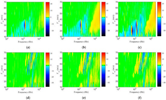
Figure 8.
ΔSPL as a function of free-stream velocity and frequency for structured porous trailing edges with the same pore diameter: (a) L04M04N04 with α = 0°, (b) L06M06N06 with α = 0°, (c) L08M08N08 with α = 0°, (d) L04M04N04 with α = 10°, (e) L06M06N06 with α = 10°, and (f) L08M08N08 with α = 10°.
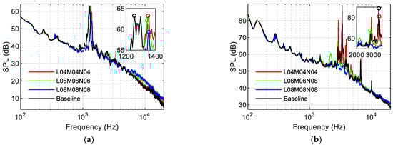
Figure 9.
Typical noise spectra between the structured porous trailing edges and the baseline trailing edge. (a) V∞ = 30 m/s, α = 0°; (b) V∞ = 60 m/s, α = 10°. Different colored circles in the zoomed inset figures illustrate the peak SPL of the different configurations.
Another trend discernible from Figure 8 is that greater noise reduction was obtained by a structured porous edge with a larger pore diameter. This is further confirmed by Figure 10, where ΔOASPL levels for the different configurations are plotted. It is shown that a maximum OASPL reduction of 2.86 dB (see Table 2) and 4.66 dB (see Table 3) can be obtained by L08M08N08 at angles of attack of α = 0° and α = 10°, respectively. The reason for this trend is that porous edges with a larger pore diameter have larger porosity (defined as the ratio of the cumulative volume of the pores to that of the total volume of the interchangeable trailing edge section [28]), and several experimental results from the references have demonstrated that noise reduction is more significant when the porosity increases [29,30].
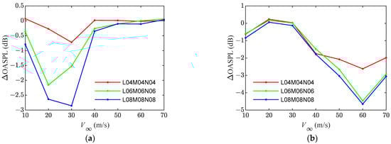
Figure 10.
ΔOASPL for structured porous trailing edges with the same pore diameter: (a) α = 0°, (b) α = 10°.
Table 2.
Summary of the OASPL for the different configurations at α = 0°.
Table 3.
Summary of the OASPL for the different configurations at α = 10°.
3.3. Effect of the Pore Coverage
Figure 11 shows the ΔSPL for structured porous trailing edges in which all three subregions, the two downstream subregions and the last downstream subregion are covered by pores of 0.6 mm from left to right, respectively. No consistent trend in noise reduction can be observed from these subfigures, partly due to the complex nature of airfoil tonal noise, as demonstrated in Section 3.1. Figure 12 plots the ΔOASPL for structured porous trailing edges with different pore coverages. It is shown that the performance of OASPL reduction is slightly different for α = 0° and α = 10°. Generally, larger OASPL reduction is observed for the configuration with smaller pore coverage at α = 0°, while better noise reduction is obtained for the porous edge with larger pore coverage at α = 10°. One of the mechanisms responsible for the noise reduction caused by porous edges [4,28,29] is that porous treatment allows for flow communication between the pressure and suction sides close to the airfoil trailing edge, and this subsequently influences the flow separation in the boundary layer. At an angle of attack of α = 10°, all of the three subregions have sufficient pressure differences to drive airflow passing through both sides of the airfoil. Therefore, porous edges with larger pore coverage provide greater noise reduction. On the other hand, due to the symmetry profile of the NACA 0012 airfoil and the resulting flow symmetry at α = 0°, a sufficient pressure difference will only occur in the area close to the trailing edge, especially at low free-stream velocities. Furthermore, in this situation, additional pores at the middle subregion and the upstream subregion will increase the risk of generating unwanted bluntness-induced noise [15,16,17]. The combined effect of these two factors results in more noise reduction for the porous edge with smaller pore coverage.
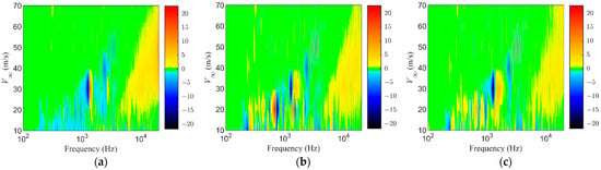
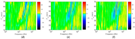
Figure 11.
ΔSPL as a function of free-stream velocity and frequency for structured porous trailing edges with different pore coverages: (a) L06M06N06 with α = 0°, (b) L00M06N06 with α = 0°, (c) L00M00N06 with α = 0°, (d) L06M06N06 with α = 10°, (e) L00M06N06 with α = 10°, and (f) L00M00N06 with α = 10°.

Figure 12.
ΔOASPL for structured porous trailing edges with different pore coverages: (a) α = 0°, (b) α = 10°.
3.4. Effect of the Pore Position
Figure 13 shows ΔSPL as a function of free-stream velocity and frequency for structured porous trailing edges when the last downstream subregion, the middle subregion, and the upstream subregion are covered by 0.6 mm pores, from left to right, respectively. Figure 14 plots the corresponding ΔOASPL. Similar to the observation in Section 3.3, noise reduction is slightly different for a zero angle of attack of α = 0° and a non-zero angle of attack of α = 10°. Generally, larger OASPL reduction is observed for L00M00N06 at α = 0°, while greater noise reduction is obtained for L06M00N00 at α = 10°. Both Ali et al. [31] and Rossignol et al. [32] have shown that vortex shedding-related noise will radiate at the solid-to-porous junction section, since a blunt edge occurs in this area due to the pores. Zhang and Chong [17] further demonstrated that the level of this unwanted noise increases with the thickness of the blunt edge at α = 0°. Since both L06M00N00 and L00M06N00 have a larger thickness of the blunt edge induced by the pores, additional bluntness-related noise will jeopardize the overall performance, and thus their ΔOASPL levels are less than L00M00N06 at α = 0°. Moreover, Liu and Chen [33] have illustrated that a porous permeable structure located in the middle of the model will generate a cavity tonal component under symmetrical flow conditions, which can also explain the better noise reduction in L00M00N06 at a zero angle of attack. On the other hand, Yakhina et al. [24] have revealed that the laminar separation bubble starts earlier on the suction side and moves downstream on the pressure side with an increasing angle of attack. Therefore, the airflow passing through pores that are distributed in the upstream subregion will have an earlier impact on the boundary layer regime and then suppress laminar instability tonal noise, which can explain the better performance of L06M00N00 at α = 10°.
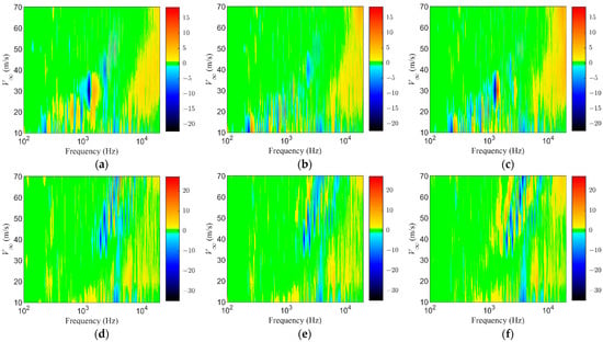
Figure 13.
ΔSPL as a function of free-stream velocity and frequency for structured porous trailing edges with different pore positions: (a) L00M00N06 with α = 0°, (b) L00M06N00 with α = 0°, (c) L06M00N00 with α = 0°, (d) L00M00N06 with α = 10°, (e) L00M06N00 with α = 10°, and (f) L06M00N00 with α = 10°.
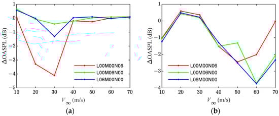
Figure 14.
ΔOASPL for structured porous trailing edges with different pore positions: (a) α = 0°, (b) α = 10°.
3.5. Effect of the Pore Arrangement Order
Figure 15 plots ΔOASPL for structured porous trailing edges with different pore arrangement orders at α = 0° in the first row and at α = 10° in the second row. The configurations with smaller pores on the upstream subregion, such as L04M05N06, L04M06N08, and L04M08N12, are marked with red lines. On the other hand, the configurations with larger pores on the upstream subregion are marked with green lines. From these subfigures, it can be seen that configurations with gradually increasing pore diameter (i.e., the red lines) generally have a higher ΔOASPL reduction. This phenomenon is consistent with the observations of Wang et al. [12], who have illustrated that metallic foams with a gradual sparse transition from the solid body to that of the free flow provided more noise reduction. However, at a high free-stream velocity and α = 10°, higher ΔOASPL reductions are observed in L06M05N04 and L08M06N04. This may be attributed to the larger pores in the upstream subregion, giving an earlier impact on the boundary layer regime and thus more noise reduction at this angle of attack, as discussed in Section 3.4.
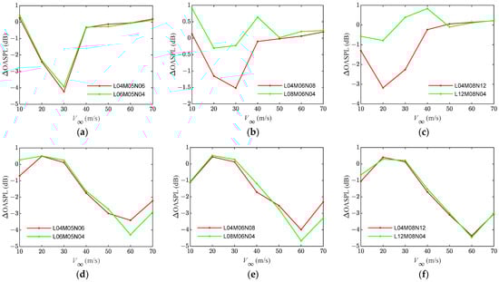
Figure 15.
ΔOASPL for structured porous trailing edges with different pore orders: (a) L04M05N06 vs. L06M05N04, α = 0°; (b) L04M06N08 vs. L08M06N04, α = 0°; (c) L04M08N12 vs. L12M08N04, α = 0°; (d) L04M05N06 vs. L06M05N04, α = 10°; (e) L04M06N08 vs. L08M06N04, α = 10°; (f) L04M08N12 vs. L12M08N04, α = 10°.
3.6. Effect of the Chordwise Spacing
Figure 16 presents the ΔSPL for structured porous trailing edges with different chordwise spacings, while Figure 17 and Figure 18 plot the corresponding typical noise spectra and ΔOASPL, respectively. It can be seen that the noise reduction performance is slightly different for a zero angle of attack of α = 0° and a non-zero angle of attack of α = 10°. At α = 0°, small-to-medium size chordwise spacing of ch = 1.0 mm and ch = 2.0 mm alternately provide the best noise reduction. On the other hand, the smallest chordwise spacing of ch = 1.0 generally outperforms ch = 2.0 mm and ch = 4.0 mm at α = 10°.
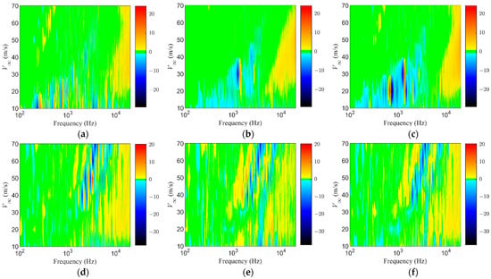
Figure 16.
ΔSPL as a function of free-stream velocity and frequency for structured porous trailing edges with different chordwise spacings: (a) ch = 4.0 mm, α = 0°; (b) ch = 2.0 mm, α = 0°; (c) ch = 1.0 mm, α = 0°; (d) ch = 4.0 mm, α = 10°; (e) ch = 2.0 mm, α = 10°; and (f) ch = 1.0 mm, α = 10°.
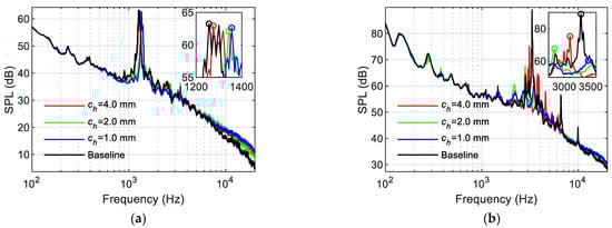
Figure 17.
Typical noise spectra between the structured porous trailing edges and the baseline trailing edge with different chordwise spacings. (a) V∞ = 30 m/s, α = 0°; (b) V∞ = 60 m/s, α = 10°. Different colored circles in the zoomed inset figures illustrate the peak SPL of the different configurations.
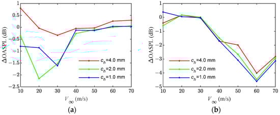
Figure 18.
ΔOASPL for structured porous trailing edges with different chordwise spacings: (a) α = 0°, (b) α = 10°.
3.7. Effect of the Spanwise Spacing
Figure 19 presents ΔSPL as a function of free-stream velocity and frequency for structured porous trailing edges with a spanwise spacing of sh = 20.0 mm, sh = 10.0 mm, and sh = 5.0 mm (from left to right), respectively. Figure 20 and Figure 21 plot the corresponding typical noise spectra and ΔOASPL, respectively. It is shown in these figures that a medium-size spanwise spacing of sh = 10.0 mm generally provides better noise reduction at a zero angle of attack of α = 0°, while the smallest spanwise spacing of sh = 5.0 mm typically provides the best noise reduction at α = 10°.
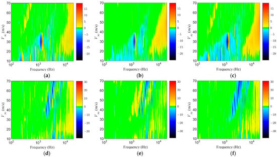
Figure 19.
ΔSPL as a function of free-stream velocity and frequency for structured porous trailing edges with different spanwise spacings: (a) sh = 20.0 mm, α = 0°; (b) sh = 10.0 mm, α = 0°; (c) sh = 5.0 mm, α = 0°; (d) sh = 20.0 mm, α = 10°; (e) sh = 10.0 mm, α = 10°; and (f) sh = 5.0 mm, α = 10°.
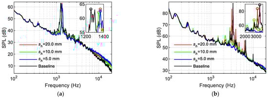
Figure 20.
Typical noise spectra between the structured porous trailing edges and the baseline trailing edge with different spanwise spacings. (a) V∞ = 30 m/s, α = 0°; (b) V∞ = 60 m/s, α = 10°. Different colored circles in the zoomed inset figures illustrate the peak SPL of the different configurations.
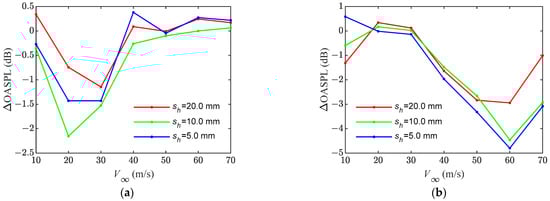
Figure 21.
ΔOASPL for structured porous trailing edges with different spanwise spacings: (a) α = 0°, (b) α = 10°.
4. Conclusions
In this paper, an experimental aeroacoustic study on reducing the tonal noise from laminar instability by using structured porous trailing edges was presented. Detailed acoustic measurements have been conducted on a symmetrical NACA 0012 airfoil with a solid trailing edge and seventeen structured porous trailing edges, under varying free-stream velocities and angles of attack. The key findings of this study are listed as follows:
- (1)
- Structured porous trailing edges can reduce the noticeable tonal noise of the symmetrical NACA 0012 airfoil. Under the same pore coverage, larger noise reduction was generally obtained by structured porous edges with a larger diameter of sub-millimeter-scale pores and gradually sparsely arranged pores transiting from the solid body to that of the free flow.
- (2)
- Due to the sensitivity of airfoil tonal noise to changes in the free-stream velocity and the geometric angle of attack, as shown in Section 3.1, the design parameters for tonal noise reduction are slightly different at a zero angle of attack (α = 0°) and a non-zero angle of attack (α = 10°).
- (3)
- At α = 0°, the pressure difference between the pressure and suction sides close to the trailing edge is relatively small, especially at low free-stream velocities. Moreover, bluntness-related vortex shedding tonal noise and cavity tonal components are more likely to occur at this angle of attack. Therefore, larger airfoil tonal noise reduction is prone to the porous parameters of small pore coverage, small-to-moderate chordwise spacing, and moderate spanwise spacing. Meanwhile, structured pores are preferably distributed on the downstream of the airfoil.
- (4)
- At α = 10°, a sufficient pressure difference between the pressure and suction surfaces can easily drive airflow passing through both sides of the airfoil. Consequently, the optimal combination of the structured porous edge is a configuration with larger pore coverage, smaller chordwise spacing, and spanwise spacing.
Due to the significant difference between the studied Reynolds number of 105 and the actual Reynolds number of 1012 for full-scale wings (e.g., Boeing 747 [4]), further research is needed on noise reduction using structured porous trailing edges at comparatively higher Reynolds numbers in the future. Another direction for future research is to reveal the underlying noise reduction mechanisms of structured porous trailing edges via numerical simulations or PIV flow field measurements.
Author Contributions
Conceptualization, Y.W. and K.Z. (Kongcheng Zuo); methodology, Y.W.; validation, P.G. and K.Z. (Kun Zhao); formal analysis, P.G.; investigation, Y.W.; resources, K.Z. (Kongcheng Zuo); data curation, V.F.K.; writing—original draft preparation, Y.W.; writing—review and editing, Y.W. and K.Z. (Kongcheng Zuo); visualization and experimental tests, P.G. and K.Z. (Kun Zhao); supervision, K.Z. (Kongcheng Zuo); modification and English edit, V.F.K. All authors have read and agreed to the published version of the manuscript.
Funding
This work was supported by the National Natural Science Foundation of China, under grant numbers 12261131502 and 12102451. Victor Kopiev was supported by the Russian Science Foundation, grant no. RSF 23-41-00023.
Institutional Review Board Statement
Not applicable.
Informed Consent Statement
Not applicable.
Data Availability Statement
The data presented in this study are available on request from the corresponding author.
Acknowledgments
The authors would like to thank the editor and anonymous referees for their helpful comments and suggestions.
Conflicts of Interest
The authors declare no conflicts of interest.
References
- Brooks, T.F.; Pope, D.S.; Marcolini, M.A. Airfoil Self-Noise and Prediction; Technical Report NASA Technical Memorandum, No. NASA RP-1218; NASA Langley Research Center: Hampton, VA, USA, 1989. [Google Scholar]
- Jaiswal, P.; Pasco, Y.; Yakhina, G.; Moreau, S. Experimental investigation of aerofoil tonal noise at low Mach number. J. Fluid Mech. 2022, 932, A37.1–A37.31. [Google Scholar] [CrossRef]
- Yang, Y.N.; Pröbsting, S.; Li, P.Y.; Liu, Y.; Li, Y. A secondary modulation mechanism for aerofoil tonal self-noise generation. J. Fluid Mech. 2022, 943, A13.1–A13.37. [Google Scholar] [CrossRef]
- Wang, Y.; Zhao, K.; Lu, X.Y.; Song, Y.B.; Bennett, G.J. Bio-inspired aerodynamic noise control: A bibliographic review. Appl. Sci. 2019, 9, 2224. [Google Scholar] [CrossRef]
- Chong, T.P.; Joseph, P.; Gruber, M. An Experimental Study of Airfoil Instability Noise with Trailing Edge Serrations. In Proceedings of the 16th AIAA/CEAS Aeroacoustic Conference (31th AIAA Aeroacoustic Conference), Stockholm, Sweden, 7–9 June 2010. AIAA Paper 2010-3723. [Google Scholar]
- Chong, T.P.; Vathylakis, A.; Joseph, P.F.; Gruber, M. Self-Noise produced by an airfoil with nonflat plate trailing-edge serrations. AIAA J. 2013, 51, 2665–2677. [Google Scholar] [CrossRef]
- Chong, T.P.; Joseph, P. An experimental study of airfoil instability tonal noise with trailing edge serrations. J. Sound Vib. 2013, 332, 6335–6358. [Google Scholar] [CrossRef]
- Serpieri, J.; Gupta, M.; Pröbsting, S.; Scarano, F. Effect of Serrated Trailing Edge on Boundary Layer Instability Noise. In Proceedings of the 21st AIAA/CEAS Aeroacoustics Conference, Dallas, TX, USA, 22–26 June 2015. AIAA Paper 2015-2363. [Google Scholar]
- Herr, M.; Dobrzynski, W. Experimental investigations in low-noise trailing-edge design. AIAA J. 2005, 43, 1167–1175. [Google Scholar] [CrossRef]
- Herr, M. Design Criteria for Low-Noise Trailing-Edges. In Proceedings of the 13th AIAA/CEAS Aeroacoustics Conference (28th AIAA Aeroacoustics Conference), Rome, Italy, 21–23 May 2007. AIAA Paper 2007-3470. [Google Scholar]
- Wang, Y.; Lai, Q.R.; Liang, Y.; Song, Y.B.; Zheng, X. Experimental Study on Instability Tonal Noise Reduction using Trailing Edge Gradient Porous Materials. In Proceedings of the 2020 International Congress on Noise Control Engineering, Seoul, Republic of Korea, 23–26 August 2020. [Google Scholar]
- Wang, Y.; Hao, N.S.; Lu, X.Y.; Tong, F.; Song, Y.B. Airfoil self-noise reduction by gradient distributed porous trailing edges. J. Aerosp. Eng. 2021, 34, 04021075. [Google Scholar] [CrossRef]
- Jiang, C.Y.; Moreau, D.; de Silva, C.; Doolan, C. Noise generation mechanisms of a micro-tube porous trailing edge. J. Sound Vib. 2024, 571, 118085. [Google Scholar] [CrossRef]
- Arcondoulis, E.; Liu, Y.; Li, Z.Y.; Yang, Y.N.; Wang, Y. Structured porous material design for passive flow and noise control of cylinders in uniform flow. Materials 2019, 12, 2905. [Google Scholar] [CrossRef]
- Carpio, A.R.; Avallone, F.; Ragni, D.; Snellen, M.; van der Zwaag, S. Quantitative criteria to design optimal permeable trailing edges for noise abatement. J. Sound Vib. 2020, 485, 115596. [Google Scholar] [CrossRef]
- Zhang, M.H.; Chong, T.P. Experimental investigation of the impact of porous parameters on trailing-edge noise. J. Sound Vib. 2020, 489, 115694. [Google Scholar] [CrossRef]
- Zhang, M.H.; Chong, T.P. Effects of porous trailing edge on aerodynamic noise characteristics. Int. J. Aeroacoust. 2020, 19, 254–271. [Google Scholar] [CrossRef]
- Chong, T.P.; Vathylakis, A.; Joseph, P.F.; Gruber, M. On the Noise and Wake Flow of an Airfoil with Broken and Serrated Trailing Edges. In Proceedings of the 17th AIAA/CEAS Aeroacoustics Conference (32nd AIAA Aeroacoustics Conference), Portland, OG, USA, 5–8 June 2011. AIAA Paper 2011-2860. [Google Scholar]
- Nash, E.C.; Lowson, M.V.; McAlpine, A. Boundary-layer instability noise on aerofoils. J. Fluid Mech. 1999, 382, 27–61. [Google Scholar] [CrossRef]
- McAlpine, A.; Nash, E.C.; Lowson, M.V. On the generation of discrete frequency tones by the flow around an airfoil. J. Sound Vib. 1999, 222, 753–779. [Google Scholar] [CrossRef]
- Pröbsting, S.; Scarano, F.; Morris, S.C. Regimes of tonal noise on an airfoil at moderate Reynolds number. J. Fluid Mech. 2015, 780, 407–438. [Google Scholar] [CrossRef]
- Arcondoulis, E.; Doolan, C.J.; Brooks, L.A.; Zander, A.C. On the Generation of Airfoil Tonal Noise at Zero Angle of Attack and Low to Moderate Reynolds Number. In Proceedings of the 18th AIAA/CEAS Aeroacoustics Conference (33rd AIAA Aeroacoustics Conference), Colorado Springs, CO, USA, 4–6 June 2012. AIAA Paper 2012-2060. [Google Scholar]
- Plogmann, B.; Herrig, A.; Würz, W. Experimental investigations of a trailing edge noise feedback mechanism on a NACA 0012 airfoil. Exp. Fluids. 2013, 54, 1480. [Google Scholar] [CrossRef]
- Yakhina, G.R.; Roger, M.; Kholodov, P.V.; Nguyen, L.; Golubev, V.V. An Integrated Study of Laminar Separation Effect on Tonal Noise Generation in Transitional Bubble. In Proceedings of the 22nd AIAA/CEAS Aeroacoustics Conference, Lyon, France, 30 May–1 June 2016. AIAA Paper 2016-3022. [Google Scholar]
- Lowson, M.V.; Fiddes, S.P.; Nash, E.C. Laminar Boundary Layer Aeroacoustic Instabilities. In Proceedings of the 32nd Aerospace Sciences Meeting & Exhibit, Reno, NV, USA, 10–13 January 1994. AIAA Paper 1994-0358. [Google Scholar]
- Geyer, T.; Sarradj, E.; Fritzsche, C. Measurement of the noise generation at the trailing edge of porous airfoils. Exp. Fluids. 2010, 48, 291–308. [Google Scholar] [CrossRef]
- Geyer, T.; Sarradj, E.; Fritzsche, C. Porous airfoils: Noise reduction and boundary layer effects. Int. J. Aeroacoust. 2010, 9, 787–820. [Google Scholar] [CrossRef]
- Sarradj, E.; Geyer, T. Noise Generation by Porous Airfoils. In Proceedings of the 13th AIAA/CEAS Aeroacoustics Conference (28th AIAA Aeroacoustics Conference), Rome, Italy, 21–23 May 2007. AIAA Paper 2007-3719. [Google Scholar]
- Herr, M.; Rossignol, K.S.; Delfs, J.; Mößner, M.; Lippitz, N. Specification of Porous Materials for Low-Noise Trailing-Edge Applications. In Proceedings of the 20th AIAA/CEAS Aeroacoustics Conference, Atlanta, GA, USA, 16–20 June 2014. AIAA Paper 2014-3041. [Google Scholar]
- Sumesh, C.K.; Jothi, T.J.S. Aerodynamic noise characteristics of a thin airfoil with line distribution of holes adjacent to the trailing edge. Int. J. Aeroacoust. 2019, 18, 496–516. [Google Scholar] [CrossRef]
- Ali, S.A.S.; Azarpeyvand, M.; da Silva, C.R.I. Trailing-edge flow and noise control using porous treatments. J. Fluid Mech. 2018, 850, 83–119. [Google Scholar]
- Rossignol, K.S.; Suryadi, A.; Herr, M.; Schmidt, J.; Tychsen, J. Experimental investigation of porous materials for trailing-edge noise reduction. Int. J. Aeroacoust. 2020, 19, 365–384. [Google Scholar] [CrossRef]
- Liu, H.R.; Chen, N.S. Test on effects of porous permeable section on trailing edge noise. Acta Aeronaut. Et Astronaut. Sin. 2017, 38, 120746. [Google Scholar]
Disclaimer/Publisher’s Note: The statements, opinions and data contained in all publications are solely those of the individual author(s) and contributor(s) and not of MDPI and/or the editor(s). MDPI and/or the editor(s) disclaim responsibility for any injury to people or property resulting from any ideas, methods, instructions or products referred to in the content. |
© 2024 by the authors. Licensee MDPI, Basel, Switzerland. This article is an open access article distributed under the terms and conditions of the Creative Commons Attribution (CC BY) license (https://creativecommons.org/licenses/by/4.0/).