Abstract
This article presents the conceptual design, operation principle, dynamic modeling, and simulation results of a discrete incremental hydraulic positioning system (DIHPS) intended for use in high-precision, heavy-load industrial automation solutions. An original solution for precise incremental step positioning using DIHPS is proposed, comprising an n-step linear double-acting hydraulic actuator (HA) with a double rod, cylinder sleeve with outflow gaps, binary valves (BVs) bleed-off into the tank, and fixed throttle valves (TRVs) at the inlets of the actuator chambers. The discrete incremental shift of the HA is determined by controlling the opening and closing of the individual BVs, and the step shift of the HA piston stops at the opening location of the BV. A dynamic model of incremental step shift for DIHPS is developed, considering the behavior and relationships of its individual elements. A dynamic model of HA with and without a hydropneumatic accumulator (HPA) is presented. HPA has been shown to effectively dampen piston vibrations and pressure peaks at the HA stop position. The design assumptions, dynamic models, and discrete incremental positioning of the DIHPS are verified by simulation tests and assessed with quantitative indicators. Innovative DIHPSs have significant practical potential in the discrete incremental positioning of heavy loads.
1. Introduction
Hydraulic positioning systems (HPS) are used to accurately and precisely position heavy loads in various industries [1]. Fast and precise movement of a HA usually requires a position measurement and a specialized controller [2]. Traditional hydraulic positioning control systems consist of actuators, proportional or servo valves, position sensors, and controllers [3]. The main problem with traditional hydraulic positioning systems is their low energy efficiency and the high cost of the control valves. In hydraulic servo drives, in which the HA is controlled in a closed loop, the positioning accuracy under heavy loads is better than 0.01 mm. The application of hydraulic servo drives in position control systems requires solving the problem of dynamic response time, position precision, and anti-interference [4]. Solutions are sought for precise control of the position of HAs under heavy loads [5].
In hydraulic positioning systems, fast on/off valves with pulse width modulation (PWM) control are used to control the HA instead of servo valves [6]. In [7], a novel hydraulic valve system was proposed, using multiple on/off valves of equal size for the control of the circulation switching of hydraulic systems.
In [8], a method was presented to control the position of the HA using on/off valves with an appropriate digital control strategy. Precise position control of HAs can be achieved without position sensors by using stepper drives. Stepper drives are an obvious concept for sensorless position control of linear or rotary hydraulic actuators [9,10,11]. In these stepper drives, the impulses sent to the switching valves are converted into precise steps of the HA displacement.
Sensorless position control is particularly desirable in the field of heavy hydraulic industrial automation. In complex machine systems with multiple hydraulic position actuators, the avoidance of position sensors and measuring accessories is important [12]. Sensorless positioning has great advantages because it does not generate high costs, does not pose a risk of failure, and does not require wiring and controller input modules. The most popular hydraulic step positioning technology is based on rotary stepper motors and linear stepper cylinders controlled by discrete digital signals [13,14]. In [15], the structure and working principle of the hydraulic stepper drive (HSD) based on the stepper motor, the HA, the three-way valve, and the screw feedback mechanism were introduced. In [16], electrohydraulic spool valves with step motors used as electromechanical transducers were described. The new concept of a proportional valve in which two-stepping motors work differentially is introduced. In [17], HSD was proposed based on five high-speed on/off valves and two miniature plunger cylinders. HSD discretizes the continuous flow rate into fixed small flow steps through the miniature plunger cylinder and realizes the state control of the drive through the logic action of the high-speed on/off valves. In [18], the modeling and control of an HSD were presented, which involved a standard differential cylinder controlled by four on/off valves in a complete bridge circuit.
Digital control is now becoming an inevitable direction of HSD development. In the control of hydraulic drives, there has been a tendency to digitize hydraulic components, which has been called digital hydraulics (DH) [19,20,21,22,23,24]. Hydraulic digital components include switch valves based on binary-valued on/off valves, also called digital valves (DVs). The use of DH with DV is a cost-effective method of replacing expensive and sensitive hydraulic servo valves to control hydraulic stepper actuators. Mass-produced DVs are the most robust, small, and inexpensive compared to proportional and servo valves, contributing to lower investment and production costs. DVs will play an important role in intelligent manufacturing with the development of Industry 4.0 [25,26]. DVs as a BV has two states, open state 1 (on) and closed state 0 (off). For state 1, the output signal, that is, the pressure and flow rate at the output of the hydraulic BV, is 1. For state 0, the output signal, that is, the pressure and flow rate at the output of the hydraulic BV, is 0. The use of BVs enabled the creation of new and more effective versions of hydraulic stepper drives and discrete incremental positioning. Digital control with hydraulic BVs, compared to hydraulic proportional and servo valves, is inexpensive, reliable, and robust. The BVs are also simpler and easier to connect to digital controllers. The on/off of the BVs is high frequency, typically 50 Hz or more, and these are these are high-speed on/off valves [27]. BVs are insensitive to contamination and leak-free in state 0. The use of high-speed BVs to control hydraulic stepper actuators (HSAs) results in greater reliability, lower energy consumption, improved positioning accuracy, shorter downtime, lower losses, and lower investment costs. However, the control of high-speed BVs is associated with many negative features, such as noise, pressure peaks, jerky motion, poor controllability, and other problems caused by their frequent opening and closing. In summary, the development of HPS is related to sensorless HSD with the use of DH with BVs.
HSAs are of limited use when moving at high speeds as they are susceptible to loss of steps. In this case, the best solution is to use incremental HSAs. Incremental actuators may perform discrete incremental or continuous incremental motion. The distinguishing feature of discrete incremental linear HSAs is a relative stepper positioning. Discrete incremental positioning means that the HSA position does not depend on the absolute position but only on the position in the previous step. Discrete incremental HSAs do not have an inherent limitation in stroke length because each subsequent step begins from the previous step. Discrete incremental HSAs perform discrete positioning, the same as in stepper drives. A discrete incremental HSA produces force and motion along a linear path. In [28], the author developed linear incremental HAs, which are a class of actuators consisting of one or more double-acting cylinders with an engaging/disengaging mechanism.
In this article, the author extends the basic concept of sensorless step positioning for linear HAs [29,30] with new and original solutions, such as the operation principle, dynamic modeling, simulation, and damping of DIHPS. The bond graph method previously used for modeling of sensorless hydraulic linear stepper actuators does not correspond to the principle of operation of DIHPS, and the simulation results refer only to the step response. The new original solutions focus on the DIHPS operating principle, its incremental step shift dynamic model with a simulation solution, and the HA stiffness model that incorporates an HPA.
Section 2 contains the conceptual design and basic operation of DIHPS controlled by BVs. In Section 3, an incremental step shift dynamic model of DIHPS was developed, consisting of models of individual elements such as a flow gap, BVs, TRVs, and HAs. In Section 4, simulation tests were carried out to confirm the design assumptions, dynamic models, and discrete incremental positioning of the DIHPS. Section 5 discusses the effects of the hydraulic stiffness of the HA on its stop position. Section 6 discusses the DIHPS dynamic model with excitation force. Section 7 discusses the impact of HPA on the effective damping of piston vibrations and pressure peaks in actuator chambers. Section 8 summarizes the conceptual design of DIHPS, its operating principle, dynamic modeling and simulation results, and a discussion of vibration damping.
2. Concept of DIHPS Solution
This study focuses on the design, dynamic modeling, and simulation of incremental step positioning using DIHPS. Compared to the conventional electrohydraulic servo system (EHSS), the EHSS provides a more accurate positioning than DIHPS. The EHSS is a feedback control system, while the DIHPS is an incremental control system based on fluid flow through the outflow gaps, hydraulic resistance balance, and force balance. EHSS uses a differential cylinder, while DIHPS uses a double-piston rod cylinder. Different pressure forces in the EHSS were impacted by the differential cylinder. Industrial EHSS includes a position controller without compensation or force control. To improve the tracking performance, an adaptive compensator is added to the EHSS in this case. The DIHPS’s positioning control is influenced by the balance of forces. Machining a DIHPS cylinder costs more than machining a servo cylinder. The cost of the servo valves and the EHSS control system is much higher than the BV in DIHPS. Mass-produced BVs are the most robust, small, and inexpensive compared to proportional and servo valves, contributing to lower investment and production costs. DIHPS’s advantage lies in its ability to accurately position large masses and compensate for excitation forces. Sensorless position control of DIHPS is highly desired in the field of heavy hydraulic industrial automation. The programming of BV has multiple advantages over servo-valves and proportional valves. BV control at the outlet, as in DIHPS, is definitely more advantageous than servo valve control at the inlet, as in EHSS.
Figure 1 shows a general schematic diagram of the DIHPS, consisting of two fixed TRVs, a double-acting HPA with a double piston rod, and a block of BVs, which operate as bleed-off valves. Discrete incremental positioning using DIHPS involves a step shift in the HA piston from the starting position after closing the BV4 valve, as shown in Figure 1, to a new position after opening any BVi valve. The actuator piston rapidly shifts to the outflow gaps, through which fluid flows from both chambers of the actuator and then bleeds off through the BVi to the tank. The piston actuator assumed a new stable position, which was the result of the balance of the pressure forces acting on it. The discrete incremental positioning of the DIHPS takes place in equal n-steps, depending on the opening of one of the BVs (BV1–BVn). BVs have two binary control states: on (1) and off (0). For solenoid BVs, the off state is the OV voltage signal, and the on state is the 24 V voltage signal.
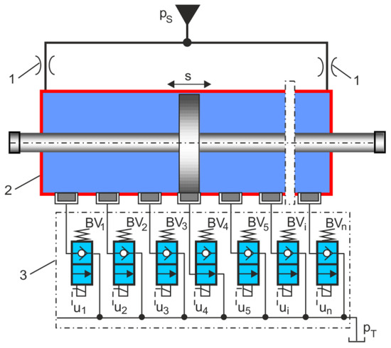
Figure 1.
General schematic diagram of DIHPS: 1, fixed TRVs; 2, double-acting HA with a double rod; 3, block of BVs.
The incremental step control of DIHPS depends on the BVi state, which can be expressed as follows:
From Equation (1), it follows that the Boole logic truth table has a constituent of ones, as shown in Table 1.

Table 1.
Boole logic truth table with a constituent of ones.
The stroke length S of the HA is as follows:
where is the initial position, and is the end position.
The HA incremental step length Δs is as follows:
where n is the step number.
The incremental step shift of the actuator piston from the start position to the new position is calculated as follows:
where is the new i-th position after opening the valve Vi, and is the start is position after closing the valve Vs.
The absolute displacement of the actuator piston is as follows:
Incremental step positioning is achieved through the use of Equations (2)–(5). The simulation model uses these formulas to implement incremental step positioning.
DIHPS can be used in heavy-industry automation, especially in cases where a strictly controlled and precise step shift of large loads is required. High-precision heavy industrial automation offers a number of advantages, including the management of heavy and awkward loads. Many manufacturing tasks lend themselves to automation in the heavy industry, where repeated heavy loads occur. DIHPS has a number of industrial applications, such as 3D printers, robots, laser devices, and the like. One of the key applications of DIHPS is XY tables, which require both high thrust forces and positioning accuracy. DIHPS can be used on roller mill tracks and conveyors in the diversion or sorting of heavy loads. Figure 2 shows schematic diagrams of the application of DIHPS for the machining of heavy workpieces, such as drilling and cutting. In such cases, DIHPS must move the object with appropriate incremental step positioning.
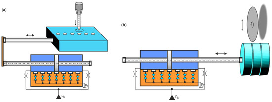
Figure 2.
Schematic diagrams of the DIHPS application for the machining of heavy workpieces in (a) drilling and (b) cutting.
After satisfactory experimental tests, DIHPS could be implemented for the machining processes of large-size heavy steel components at the Celsa Steel Mill (CSM) in Poland. CSM is a leading European manufacturer of open die forgings for strategic industries: power generation, oil and gas, engine, tool steel, and metal processing [31]. Forged components are made for the world’s largest suppliers of wind turbines, high-power plant turbines, and global corporations in the energy and mining sectors.
3. Dynamic Model of Incremental Step Shift of DIHPS
The conceptual diagram presented in Figure 3 explains the operation principle of the DIHPS in detail. DIHPS consists of an n-step linear double-acting HA with a double rod, a cylinder sleeve with outflow gaps, BVs that bleed into the tank, and fixed TRVs at the inlets of the actuator chambers. The special HA design included an inner sleeve with outflow gaps and an external sleeve with connections. When the BV is in the on state, it allows bleed flow into the tank. When it is in the off state, it blocks the unidirectional flow. BV used as on/off valves is of the 2/2 (two-way, two-position) type, poppet seat, normally closed, and coil-controlled. Seat valves respond more quickly than other valves (i.e., spool valves). The DIHPS is powered by a constant pressure hydraulic source ps = const. Two identical fixed TRVs were placed at the inlets on the right and left sides of the actuator chamber.
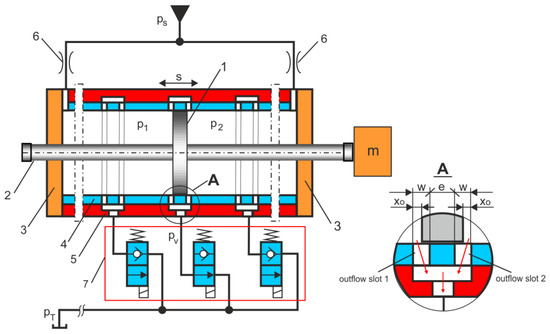
Figure 3.
Diagram of the DIHPS solution: 1, actuator piston; 2, actuator piston rod; 3, cylinder end caps; 4, inner sleeve with outflow gaps; 5, external sleeve with connections; 6, fixed TRVs; 7, block of BVs.
3.1. Outflow Gap Model
Figure 4 shows the different distinctive positions of the actuator piston in relation to the outflow gaps 1 and 2. Two flow slots with negative overlaps are sharp flow edges (explained in detail in A in Figure 3). After opening the i–th BV, there was a pressure drop in the actuator chamber. Because of the pressure difference Δp = |p1−p2|, the actuator piston moves rapidly to the flow position through the outflow gaps 1 and 2. For each distinguished position of the actuator piston, the flow rate qvij is marked, where i is the number of actuator chambers, and j is the number of flow gaps.
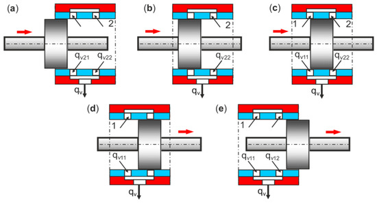
Figure 4.
Different distinctive positions of the actuator piston: (a) flows and from chamber 2, (b) flow from chamber 2, (c) flow from chamber 1 and flow from chamber 2, (d) flow from chamber 1, (e) flows and from chamber 1.
The shape of the edge between the actuator piston and the flow gap largely defines the change in the cross-sectional area and, therefore, the characteristics of the flow. Based on the different characteristic positions of the actuator piston, the static characteristics of the cross-sectional area Aij of the flow through the two gaps were determined, as shown in Figure 5.
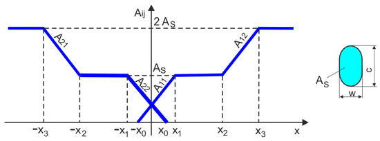
Figure 5.
Static characteristics of the cross-sectional flow area Aij of the gap as a function of the width x of the outflow gap.
From Detail A (Figure 3) and static characteristics (Figure 6), the range of opening x flow gaps is a result:
where is the width of the outflow gap at the initial symmetric position of the actuator piston, e is the width of edge, and w is the width and length of the outflow gap.
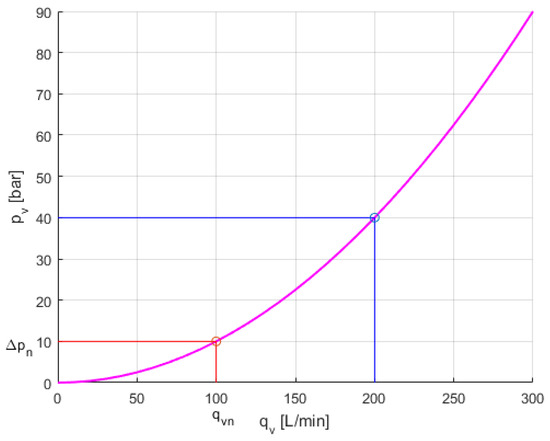
Figure 6.
Relationship between pressure drop pν and flow rate qν of BV: red line for the nominal parameters, blue line for the BV parameters.
For the full opening of the outflow gap, the cross-sectional area of the flow is the following:
where c is the length of the outflow gap.
In the simulation calculations, the equivalent cross-sectional area was assumed as:
where l is the equivalent gap length.
The general formula for the flow rate qvij, from the i-th actuator chamber to the j-th outflow gap, is as follows:
where Aij is the cross-sectional area, x is the opening of the gaps, pi is the pressure in the i-th actuator chamber, pv is the pressure in the outlet line to the on/off valve, ρ is the density of the hydraulic fluid, and Cd is the discharge coefficient, whose values for sharply edged orifices and turbulent flow can be theoretically calculated by [32]:
The flow through the flow gaps takes the final form,
where Kq is the flow gap coefficient, .
The pressure drops in the flow gap result from (12):
where Rij is the hydraulic resistance of the on/off valve,
3.2. BV Dynamic Model
Depending on the position of the actuator piston relative to the outflow gaps, as shown in Figure 4, the flow rate that bleeds through the BV into the tank results from the flow continuity equations as follows:
The BV is either completely closed (off state) or completely open (on state). The BV is modeled as an orifice valve with turbulent flow. The flow rate of through the BV with bleed-off into the tank is written in the following form:
where Cd is the flow rate coefficient, is the cross-section area, ρ is the density of hydraulic fluid, Δ is the pressure drop, is the inlet pressure, and pT is the outlet pressure in the tank, where pT ≈ 0.
Equation (16) is finally written as follows:
In the BV, the local hydraulic resistance depends on the pressure drop and the flow rate. The pressure drop caused by local resistance in the control valve is calculated using a semi-empirical formula based on the nominal pressure and flow, which is usually provided in catalogues, data sheets, or hydraulic textbooks. The nominal flow rate at the nominal pressure drop Δpn is defined as follows:
From comparisons of (17) and (18), it follows that,
where Kvn is the coefficient of the nominal parameters,
The nominal flow rate is a measure of the volumetric flow that passes through the valve under a specified operating condition. For flow control valves, such as BV, the nominal flow rate is determined at the nominal pressure drop Δpn, which is typically 10 bar.
The pressure result from (19) is as follows:
where Rv is the hydraulic resistance of the BV,
Figure 6 shows the relationship between pressure drop and flow rate ( − ) for 100% opening the BV when = .
Numerical calculations performed during the simulation use the relationship between pressure drop and flow rate through BV.
Opening and closing of BV are related to revealing and covering the cross-section , which is the result of shifting the valve slider:
where dn is the nominal diameter, y is the shift of valve spool depending on the voltage uv on the solenoid coil, 0 ≤ y ≤ ymax for 0 ≤ uv ≤ uvs,
where ymax is the maximum shift of the valve spool (100% open BV), uv is the voltage input signal, uvs is the set voltage input signal, and u is the binary input signal,
The dynamic model of the solenoid-controlled BV can be presented as a first-order differential equation as follows [33]:
where T is the time constant of the valve, and K is the gain factor of the valve.
The BV is controlled by a modulation frequency ranging from 200 to 1000 Hz. Figure 7 shows the dynamic response of the BV during the setting of the binary input signal of two frequencies.
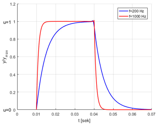
Figure 7.
Dynamic response of BV when setting a binary input signal.
3.3. TRV Dynamic Model
Two fixed TRVs with constant hydraulic resistance are located between the source of constant hydraulic pressure ps and the actuator chambers. The constant hydraulic pressure source maintains the specified pressure regardless of the flow rate of the power source. The flow rate through the TRVs is determined as follows:
where is the flow rate through the TRVs to the i-th actuator chamber, Cdt is the flow rate coefficient, At is the cross-sectional area in the TRV, ps is the pressure source, pi is the pressure in i-th actuator chamber, Δpi is the pressure drop at the the TRV to the i-th actuator chamber, and ρ is the density of hydraulic fluid.
The nominal flow rate is determined at a nominal pressure drop Δptn as follows:
From comparison (27) and (28) for a fixed constant cross-sectional area At, is obtained:
where Ktn is the coefficient of nominal parameters of TRV,
The pressure drop in the TRV is due to (27),
where Rt is the hydraulic resistance of the TRV,
3.4. HA Dynamic Model
Double-acting HAs with a double-piston rod are called symmetric actuators because they provide equal forces in both directions. In this HA, the actuator piston areas were identical; therefore, the piston speeds in both directions were the same.
Applying Newton’s second law of motion, the equation for the balance of forces in an HA can be written as follows:
where s is the step shift of the actuator piston, m is the load mass, b is the viscosity coefficient, A is the effective action area of the actuator piston, and p1 and p2 are the pressure in the actuator chambers.
In the dynamic model, the first-order differential equation is used, and then (33) is as follows:
where is the speed of the actuator piston.
Two states will be considered in the simulation modeling, the instantaneous state according to Figure 4a, and the steady state according to Figure 4c. For these states, the balance of the flow rates for both chambers of the actuator can be expressed as follows:
The system of Equations (35) and (36) has been converted to the form,
4. Results of the Simulation Test
The accuracy of the DIHPS operation was verified using its dynamic model during simulation tests. In simulation tests, the dynamic responses of the DIHPS were examined during the step shift of the actuator piston. Before the simulation test, the selection of the hydraulic resistance at the stop position of the DIHPS was verified based on the hydraulic resistance circuits shown in Figure 8.
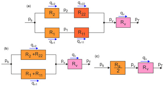
Figure 8.
Hydraulic resistance circuits in the stop position of the DIHPS: (a) hydraulic resistance circuit, (b) equivalent hydraulic resistance circuit, and (c) equivalent hydraulic resistance.
In the stop position of the DIHPS, there is a balance of forces acting on the actuator piston and symmetrical hydraulic resistance on both sides of the piston,
and
The selection of unknown pressure results from the equivalent hydraulic resistance,
In the simulation tests performed in the Matlab&Simulink R2020a software of MathWorks, the following basic parameters of constant values were introduced: ps = 10 MPa, m = 50 kg, b = 2500 Nsm−1, D = 0.05 m, d = 0.025 m, S = 0.1 m, K = 1800 MPa, ρ = 860 kgm−3, R1 = R2 = 8.26 × 10¹¹ Pa s2 m−8, Rv = 3.9 × 10¹¹ Pa s2 m−8, R11 = R22 = 1.80 × 10¹³ Pa s2 m−8, and the actuator piston step by s = 0.02 m, and the piston step shift is si = 0.02, 0.04, 0.06, 0.08, and 0.1 m. The full list of simulation parameters is provided in Appendix A Table A1.
Figure 9 shows the dynamic response parameters of the DIHPS during step incremental positioning, the step shift s of the actuator piston, the speed of the actuator piston, and the pressure p1 and p2 in the actuator chambers.
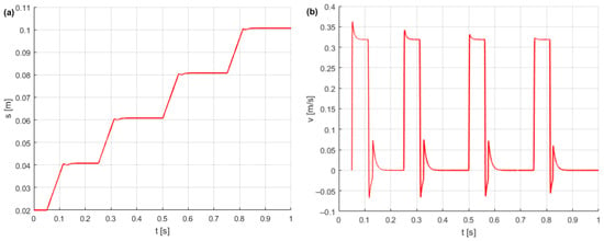
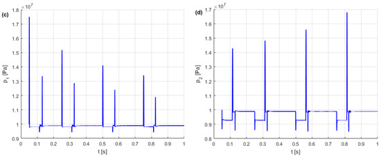
Figure 9.
Dynamic response parameters of the DIHPS during incremental step positioning: (a) step shift of the actuator piston, (b) speed of the actuator piston, and (c,d) pressure in the actuator chambers.
Simulation tests confirmed the accuracy of the design assumptions, the functionality of the dynamic model, and the achievability of the specified incremental step shift of the DIHPS.
Based on the simulation results, it is possible to estimate the position error of the HA piston. The estimated step error of the piston from si for a set position sis relative to step s is expressed as follows:
The precision of the step position of the HA depends on the mass load because, already, for m = 50 kg, the ≈ 1%.
Typically, the positioning accuracy of an HA is related to the stroke length. The step error of the piston estimated to the stroke length S is as follows:
then you obtain ≈ 0.2% for m = 50 kg.
A quantitative method was developed in [34] to evaluate different hydraulic positioning structures based on specific influence factors.
Dynamic characteristics show disturbances in the displacement and velocity of the actuator piston, as well as pressure peaks in the actuator chambers, which are the result of hydraulic shock when the BV is closed and opened. Hydraulic shock occurs when the hydraulic fluid flow suddenly stops or increases rapidly. Hydraulic shock is the result of the change in kinetic energy into potential energy (positive hydraulic shock) when the valve is closed or the change in potential energy into kinetic energy (negative hydraulic shock) when the valve is opened.
5. Hydraulic Stiffness of HA
Figure 9c shows the pressure peaks during the step shift of the actuator piston, with the highest pressure peaks occurring at extreme positions of the actuator piston. This phenomenon is caused by the compressibility of the hydraulic oil in the actuator chambers. Due to their compressibility, hydraulic fluids behave like hydraulic springs. The stiffness of the actuator chamber depends on the stiffness of the hydraulic oil and is defined as follows:
where k1, k2 are the hydraulic stiffness in the actuator chambers.
The shift of the actuator piston causes a change in the volume in both chambers in proportion to the effective area A of the piston and inversely proportional to the hydraulic capacity C1 and C2, and thus the hydraulic stiffness of a symmetrical HA results from the series connection of the hydraulic oil springs as follows:
for 0 ≤ s ≤ S,
natural frequency f of the HA under mass load,
For the simulation parameters adopted and step s = 0.04 m, the hydraulic stiffness HA is k(s) = 1.4 × 10⁷ N/m and the natural frequency is f(s) = 86 Hz.
Figure 10 shows the relative hydraulic stiffness and the relative natural frequency of the HA as a function of piston stroke. Note that the stiffness k(s) and the natural frequency f(s) for s = 0, s = S are infinite.
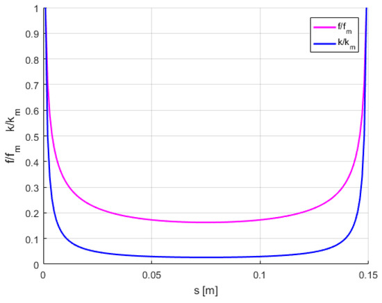
Figure 10.
Relative hydraulic stiffness and relative natural frequency of the HA as a function of the piston stroke.
After reaching the assumed DIHPS step position and closing the BV, the HA becomes stiff, as shown in Figure 11.
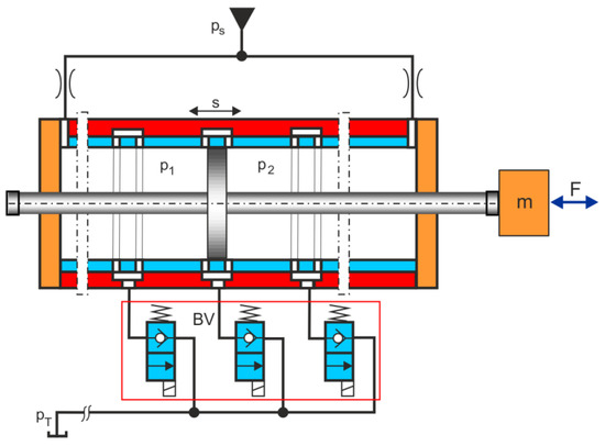
Figure 11.
DIHPS diagram with a stiff HA loaded with an excitation force F.
For a given piston step s, the mechanical model of stiff HA excited by force F is as follows:
Figure 12 shows the dynamic responses of a rigid HA excited by a constant force.
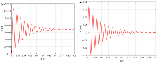
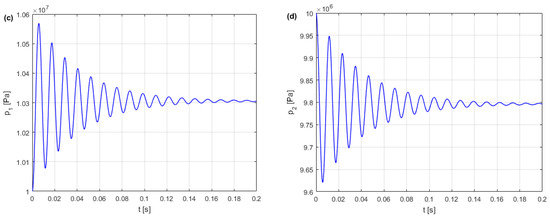
Figure 12.
Dynamic response of the stiff HA excited by a constant force F = 1000 N: (a) vibration of the piston, (b) fluctuation of the piston speed, and (c,d) pulsation pressure in the actuator chambers.
Figure 13 shows the resonance vibration parameters of a rigid HA excited by a cyclic force.
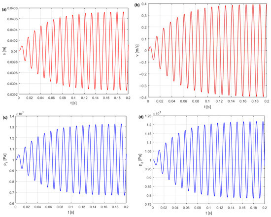
Figure 13.
Resonant vibration parameters of the stiff HA excited by a cyclic force: (a) piston vibration, (b) piston speed fluctuation, (c,d) pulsation pressure in the actuator chambers.
The hydraulic stiffness of the HA in the stop position influences the dynamic behavior of the DIHPS. HA subjected to load disturbances such as excitation force is susceptible to vibration. In an HA, there can be a wide spectrum of pressure pulsation frequencies [35]. In the case of constant excitation force, the vibrations of the HA piston are suppressed, and the accompanying pressure pulsations disappear. When the HA is excited by a cyclic force, the vibrations are not dampened, and the accompanying pressure pulsations do not disappear. An excitation force limited to harmonic vibration was introduced to excite HA,
where F0 is a constant excitation force, and fe is the excitation frequency.
When a stiff HA is subjected to an external vibration generated by an excitation force of the same frequency as the HA frequency (f = fe), the actuator piston begins to vibrate and generate pressure pulsations.
Vibration resonance must be avoided because the maximum pressure pulsations that arise can seriously damage the hydraulic system and significantly shorten its life. If there are vibrations near the resonance, a pulse shock absorber (pressure pulsation damper) should be used in hydraulic pipelines connected to the HA. The HA parameters should be selected to avoid resonance vibrations. The natural frequency of the HA is usually higher than the frequency of the excitation force (f > fe).
6. DIHPS Dynamic Model with Excitation Force
The simulation tests presented in Section 4 involved DIHPS incremental step shifts with a constant mass load of m. In this section, the dynamic response of the stiff HA is verified by introducing a constant excitation force F, which is a disturbance force. Currently, the dynamic model (34) is being considered, taking into account the constant excitation force F,
Figure 14 shows a DIHPS diagram with a HA loaded with a bidirectional constant excitation force F.
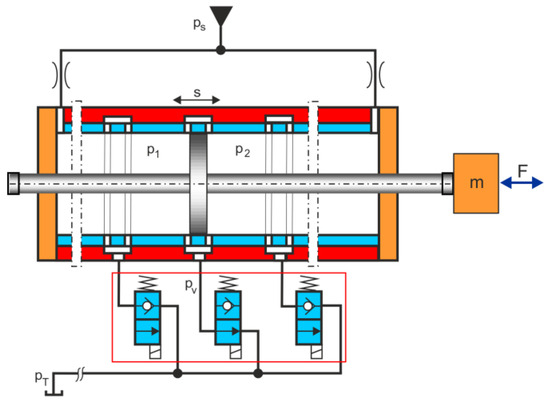
Figure 14.
DIHPS diagram with a HPA loaded with a constant excitation force F.
Figure 15 shows the dynamic response parameters of the DIHPS for a single-step shift of the piston actuator with and without a constant excitation force.
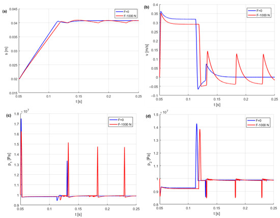
Figure 15.
Dynamic response parameters of the DIHPS for a single-step shift of the actuator piston with and without constant excitation force: (a) single-step shift of the actuator piston, (b) speed of the actuator piston, and (c,d) pressure in the actuator chambers.
The dynamic response of the actuator piston during a single-step shift was analyzed after introducing a constant excitation force F = 1000 N. After introducing a constant excitation force, cyclic piston vibrations, piston speed jumps, and pressure peaks were observed. These disturbed the piston’s position and affected the accuracy of step incremental positioning. To improve the accuracy of step-incremental positioning of HA subjected to an excitation force, HPA pressure pulsation damping was used.
7. DIHPS Dynamic Model with HPA
The HPA was connected to the actuator chamber to effectively dampen piston vibrations and pressure peaks. The HPA is a gas-charged accumulator with a hydraulic fluid chamber and a gas (nitrogen) chamber separated by a gas-tight partition (piston, bladder, and diaphragm). A diaphragm (membrane) type HPA was used as a pressure-pulsation damper [36]. Figure 16 shows a diagram of the DIHPS with the HPA connected to the actuator chamber on the F side.
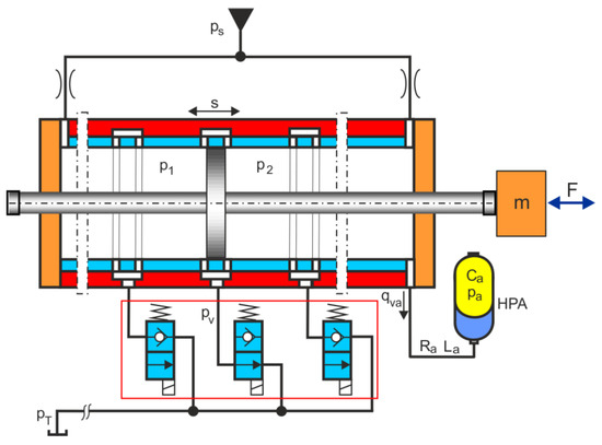
Figure 16.
DIHPS diagram with the HPA connected to the actuator chamber.
The dynamic model (51) of the DIHPS supplemented with the flow rate balance in the actuator chamber is as follows:
The HPA and the hydraulic tube connecting to the actuator chamber can be modeled with lumped elements connected in a series RLC (R is the hydraulic resistance, L is the hydraulic inductance, and C is the hydraulic conductance), according to the analogy between hydraulic and electric circuits [37,38].
The HPA model contains two first-order differential equations, the flow rate equation in the connected tube and the gas compressible equation, as follows:
The notation of Equation (51) in numerical solutions is as follows:
where is the flow rate in the hydraulic tube, p2 is the fluid pressure in the actuator chamber, and pa is the gas pressure in the HPA,
Ca is the gas capacitance of the HPA,
where p0 is the initial pressure (p0 = 4 MPa), V0 is the initial volume (V0 = 0.001 m3), and κ is the adiabatic exponent in the case of a diatomic gas as N2 nitrogen (κ = 1.4).
La is the hydraulic inductance of the hydraulic tube (hydraulic inductance describes the pressure difference required for a change in flow rate and is based on mass inertia),
where ρ is the density of hydraulic oil, lh is the length of the hydraulic tube (lh = 0.05 m), and Aa is the cross-section of the hydraulic tube,
where dh is the diameter of the hydraulic tube (dh = 0.005 m).
In the HPA connecting tube during hydraulic shock, the kinetic energy is converted into potential energy; therefore, the hydraulic resistance caused by the pipe impedance refers to the wave resistance inside a tube,
where a is the wave propagation speed (speed of sound in the fluid),
It is important to note that the hydraulic resistance caused by the flow resistance is smaller than the hydraulic resistance caused by the wave resistance.
Figure 17 compares the undamped and damped DIHPS dynamic response parameters for a single-step shift of the actuator piston with a constant excitation force of F = 1000 N, representing the disturbance force. By comparing the dynamic responses of DIHPS shown in Figure 17, the effectiveness of HPA was demonstrated in damping piston vibrations and pressure peaks in the actuator chamber. Pressure peaks and piston vibrations caused a decrease in the accuracy of the DIHPS position. HA pressure peaks cause pressure fluctuations in hydraulic pipelines and connecting elements, which contribute to mechanical vibrations, fatigue damage, and harmful noise. The mechanical vibrations of the actuator piston affect devices and machines, leading to their failure or even damage to structural elements. Usually, piston vibrations and pressure pulsations caused by external forces are not considered in HA.
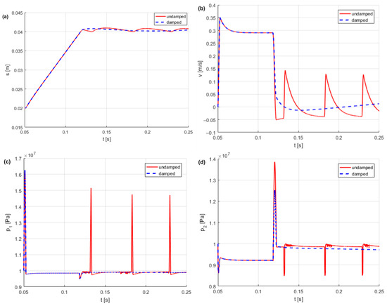
Figure 17.
Comparison of damped and undamped DIHPS dynamic response parameters for a single step shift of the actuator piston: (a) step shift of the actuator piston, (b) speed of the actuator piston, and (c,d) pressure in the actuator chambers.
8. Conclusions
This article presents a new DIHPS operating principle, its original dynamic model with a simulation solution, and an HA stiffness model considering an HPA. The incremental step shift of the DIHPS is possible due to its new design concept and the principle of operation, consisting of the symmetrical arrangement of the outflow slots in relation to the actuator piston, through which the fluid flows from the actuator chambers to the open i-th BV at the bleed off to the tank. The advantage of placing BVs at the bleed to the tank is that flow disturbances are not generated in the HA, as is the case with inlet valves.
Since there is no similar solution to DIHPS, the factors that determine the properties of DIHPS compared to other positioning methods are highlighted:
- -
- positioning speed: high; the opening size of the BV can be large;
- -
- positioning accuracy: low, large radial clearance between cylinder and piston;
- -
- positioning resolution: low, limited distances between the outflow gaps;
- -
- positioning range: low, limited number of outflow gaps;
- -
- response speed: high; opening of the BV can be quick;
- -
- working force: low, the chambers on both sides of the piston are supplied with pressure fluid;
- -
- cost: medium, simple structure, and moderate requirements for component machining precision;
- -
- location limit: high; location depends on positioning resolution and positioning range.
In DIHPS, reliability, repeatability, fault tolerance, zero leakage, low operating cost, and lower cost of spare parts are the most important.
Simulation tests confirmed the accuracy of the design assumptions, the functionality of the dynamic model, and the achievability of the specified DIHPS incremental step shift. The hydraulic resistance of the DIHPS was verified on the basis of the circuit of the hydraulic resistance. After reaching the set incremental step position, the DIHPS entered the stop position, where the stiffness of the hydraulic oil in the actuator chambers was significant. An HA stiffness model was defined for the DIHPS stop position to determine the relative hydraulic stiffness and natural frequency as functions of the actuator piston position. The dynamic response parameters of the HA stiffness for a single-step shift of the piston actuator were verified with and without constant excitation force. Hydraulic stiffness has been shown to have a significant impact on the dynamic behavior of the DIHPS in the stop position. The HPA is connected to the actuator chamber to effectively dampen the vibrations of the piston, and the pressure peaks at the stop position of the HA. The HPA and hydraulic damping tube connected to the actuator chamber were modeled using a lumped element RLC connected in series. The damping effectiveness of the HPA was proven by comparing the damped and undamped dynamic response parameters of the HA for a single-step shift of the actuator piston. The results of the simulation tests were used to develop a DIHPS prototype that was subjected to experimental tests. The execution of DIHPS is complex, as it requires precise machining of step-distant outflow gaps.
Incremental step positioning using DIHPS is simpler and cheaper because it operates in an open loop without feedback, which is beneficial in heavy industrial automation to position large masses in shipbuilding, mining, steel mill, metallurgy, and construction.
Funding
This research received no external funding.
Institutional Review Board Statement
Not applicable.
Informed Consent Statement
Not applicable.
Data Availability Statement
Data are contained within the article.
Conflicts of Interest
The author declares no conflicts of interest.
Abbreviations
| BV | binary valve |
| DH | digital hydraulic |
| DIHPS | digital incremental hydraulic positioning system |
| DV | digital valve |
| HA | hydraulic actuator |
| HPA | hydropneumatics accumulator |
| HPS | hydraulic positioning system |
| HAS | hydraulic stepper actuator |
| HSD | hydraulic stepper drive |
| PWM | pulse width modulation |
| TRV | throttle valve |
Appendix A

Table A1.
Simulation parameters.
Table A1.
Simulation parameters.
| Symbol | Value | Unit | Quantity |
|---|---|---|---|
| ps | 10 | MPa | The supply pressure |
| D | 0.05 | m | Diameter of the piston |
| d | 0.025 | m | Diameter of the piston rod |
| A | 1.5 × 10⁻³ | m2 | Area of the actuator piston |
| S | 0.1 | m | Stroke of the cylinder piston |
| s | 0.02 | m | Incremental step |
| m | 50 | kg | Load mass |
| b | 2500 | Ns/m | Viscous friction coefficient |
| ρ | 860 | kg/m3 | The density of the oil |
| K | 1600 | MPa | The bulk modulus of oil |
| l | 0.004 | m | Equivalent gap length |
| x0 | 0.002 | m | Width of the gap |
| R11 | 1.7 × 10¹³ | Pa s2 m−8 | Hydraulic resistance |
| R22 | 1.7 × 10¹³ | Pa s2 m−8 | Hydraulic resistance |
| R1 | 8.26 × 10¹¹ | Pa s2 m−8 | Hydraulic resistance |
| R2 | 8.26 × 10¹¹ | Pa s2 m−8 | Hydraulic resistance |
| 3.9 × 10¹¹ | Pa s2 m−8 | Hydraulic resistance | |
| Rt | 8.26 × 10¹¹ | Pa s2 m−8 | Hydraulic resistance |
| Cd | 0.61 | Valve flow coefficient | |
| Kq | 0.029 | ms/N1/2 | Flow gap coefficient |
| F0 | 1000 | N | External excitation force |
| p0 | 4 | MPa | Initial pressure in HPA |
| V0 | 0.001 | m3 | Initial volume in HPA |
| κ | 1.4 | Adiabatic exponent | |
| lh | 0.05 | m | Length of the hydraulic tube |
| dh | 0.005 | m | Diameter of the hydraulic tube |
| k | 1.47 × 10⁷ | N/m | Hydraulic stiffness |
| f | 86 | Hz | HA natural frequency |
| a | 1446 | m/s | Wave propagation speed |
| pn | 1 | MPa | Nominal pressure |
| 0.0011 | m3/s | Nominal flow rate | |
| Kn | 1.6 × 10⁻⁶ | m3/sPa1/2 | Constant coefficient |
| T | 0.005 | s | Time constant of BV |
| K | 1 | m/V | Gain factor of the BV. |
References
- Manring, N.D.; Fales, R.C. Hydraulic Control Systems; John Wiley & Sons, Inc.: Hoboken, NJ, USA, 2020. [Google Scholar]
- Hou, T.; Kou, Z.; Wu, J.; Jin, T.; Su, K.; Du, B. Research on positioning control strategy for a hydraulic support pushing system based on iterative learning. Actuators 2023, 12, 306. [Google Scholar] [CrossRef]
- Burecek, A.; Hruzík, L.; Martin Vasina, M. Simulation of dynamics of hydraulic system with proportional control valve. EPJ Web Conf. 2016, 114, 02008. [Google Scholar] [CrossRef]
- Guo, Y.-Q.; Zha, X.-M.; Shen, Y.-Y.; Wang, Y.-N.; Chen, G. Research on PID position control of a hydraulic servo system based on Kalman genetic optimization. Actuators 2022, 11, 162. [Google Scholar] [CrossRef]
- Zhou, R.; Meng, L.; Yuan, X.; Qiao, Z. Research and experimental analysis of hydraulic cylinder position control mechanism based on pressure detection. Machines 2022, 10, 1. [Google Scholar] [CrossRef]
- Ma, M.; Li, F.; Hao, L.; Han, Y. Mechanism modeling and Simulink simulation analysis of digital hydraulic cylinder. J. Phis. Conf. Ser. 2020, 1624, 022010. [Google Scholar] [CrossRef]
- Kucybala, P.; Sobczyk, A. The use of digital hydraulic to the position control of hydraulic cylinder. J. KONES Powertrain Transp. 2016, 23, 1–6. [Google Scholar]
- Pan, M.; Plummer, A.; El Agha, A. Theoretical and experimental studies of a switched inertance hydraulic system in a four-port high-speed switching valve configuration. Energies 2017, 10, 780. [Google Scholar] [CrossRef]
- Gradl, C.; Plöckinger, A.; Scheidl, R. Sensorless position control with a hydraulic stepper drive—Concept, compression modeling and experimental investigation. Mechatronics 2016, 35, 91–101. [Google Scholar] [CrossRef]
- Gradl, C.; Scheidl, R. Performance of an energy efficient low power stepper converter. Energies 2017, 10, 445. [Google Scholar] [CrossRef]
- Plöckinger, A.; Grad, C.; Scheid, R. High accuracy sensorless hydraulic stepping actuator. In Proceedings of the Eighth Workshop on Digital Fluid Power, Tampere, Finland, 24–25 May 2016. [Google Scholar]
- Bolognani, S.; Oboe, R.; Zigliotto, M. Sensorless full-digital PMSM drive with EKF estimation of speed and rotor position. IEEE Trans. Ind. Electron. 1999, 46, 84–191. [Google Scholar] [CrossRef]
- Liu, B. The Study of Exactly Control Stepping Motor. Master’s Thesis, Shandong University, Jinan, China, 2010. [Google Scholar]
- Kogler, H.; Schöberl, M.; Scheidl, R. Passivity-based control of a pulse-width mode operated digital hydraulic drive. Proceedings of the Institution of Mechanical Engineers. Proc. Inst. Mech. Eng. Part I J. Syst. Control Eng. 2019, 233, 656–665. [Google Scholar]
- Milecki, A.; Ortmann, J. Electrohydraulic linear actuator with two stepping motors controlled by overshoot-free algorithm. Mech. Syst. Signal. Process. 2017, 96, 45–57. [Google Scholar] [CrossRef]
- Qiu, H.; Su, Q. Simulation research of hydraulic stepper drive technology based on high speed on/off valves and miniature plunger cylinders. Micromachines 2021, 12, 438. [Google Scholar] [CrossRef] [PubMed]
- Stauch, C.; Rudolph, J. Control-oriented modelling and development of a model-based switching algorithm for a digital hydraulic independent metering cylinder drive. Proc. Inst. Mech. Eng. Part I J. Syst. Control Eng. 2017, 231, 66–81. [Google Scholar] [CrossRef]
- Paloniitty, M.; Linjama, M. High-linear digital hydraulic valve control by an equal coded valve system and novel switching schemes. Proc. Inst. Mech. Eng. Part I J. Syst. Control Eng. 2018, 232, 258–269. [Google Scholar] [CrossRef]
- Linjama, M.; Laamanen, A.; Vilenius, M. Is it time for digital hydraulics? In Proceedings of the SICFP’03 The Eighth Scandinavian International Conference on Fluid Power, Tampere, Finland, 7–9 May 2003. [Google Scholar]
- Zhang, Q.; Kong, X.; Yu, B.; Ba, K.; Jin, Z.; Kang, Y. Review and development trend of digital hydraulic technology. Appl. Sci. 2020, 10, 579. [Google Scholar] [CrossRef]
- Azzam, I.; Pate, K.; Garcia-Bravo, J.; Breidi, F. Energy savings in hydraulic hybrid transmissions through digital hydraulics Technology. Energies 2022, 15, 1348. [Google Scholar] [CrossRef]
- Antonelli, M.G.; Brunetti, J.; D’Ambrogio, W.; Fregolent, A.; Nataletti, P. Development of a digital twin for a hydraulic, active seat suspension system. Machines 2023, 11, 708. [Google Scholar] [CrossRef]
- Liu, Y.; Wang, Q.; Xu, D.; Chen, Q. Digital hydraulic design for low-specific-speed propeller runners with fixed blades. Symmetry 2022, 14, 2250. [Google Scholar] [CrossRef]
- Rituraj, R.; Scheidl, R.; Ladner, P.; Lauber, M.; Plöckinger, A. Prototyping and experimental investigation of digital hydraulically driven knee exoskeleton. Energies 2022, 15, 8695. [Google Scholar] [CrossRef]
- Brandstetter, R.; Deubel, T.; Scheidl, R.; Winkler, B.; Zeman, K. Digital hydraulics and Industrie 4.0. Proc. Inst. Mech. Eng. Part I J. Syst. Control Eng. 2017, 231, 82–93. [Google Scholar] [CrossRef]
- Xu, B.; Shen, J.; Liu, S.; Su, Q.; Zhang, J. Research and Development of Electro-hydraulic Control Valves Oriented to Industry 4.0: A Review. Chin. J. Mech. Eng. 2020, 33, 29. [Google Scholar] [CrossRef]
- Li, C.; Liu, X.; Wang, X.; Chen, J.; Wang, Y. Optimization of multi-way valve structure in digital hydraulic system of loader. Energies 2021, 14, 700. [Google Scholar] [CrossRef]
- Hochwallner, M. On Motion Control of Linear Incremental Hydraulic Actuators; Dissertation No. 1888; Linköping Studies in Science and Technology, Linköping University: Linköping, Sweden, 2017. [Google Scholar]
- Dindorf, R.; Woś, P. Sensorless position control system of hydraulic linear stepper actuator. In Proceedings of the EM’2028 24rd International Conference Engineering Mechanics, Svratka, Czech Republic, 14–17 May 2018; pp. 185–188. [Google Scholar]
- Dindorf, R.; Woś, P. Sensorless step positioning of hydraulic linear actuator. Trans. Eng. Mech. 2018, 11, 169–174. [Google Scholar]
- Dindorf, R.; Wos, P. Energy-Saving Hot Open Die Forging Process of Heavy Steel Forgings on an Industrial Hydraulic Forging Press. Energies 2020, 13, 1620. [Google Scholar] [CrossRef]
- Jelali, M.; Kroll, A. Hydraulic Servo Systems—Modelling, Identification and Control; Springer: Berlin/Heidelberg, Germany, 2003. [Google Scholar]
- Xu, X.; Han, X.; Liu, Y.; Liu, Y.; Liu, Y. Modeling and dynamic analysis on the direct operating solenoid valve for improving the performance of the shifting control system. Appl. Sci. 2017, 7, 1266. [Google Scholar] [CrossRef]
- Li, Q.; Uzunov, O. Study on the relationship between structure and properties of electro-hydraulic positioning actuators. Arch. Mech. Eng. 2024, 1, 1–21. [Google Scholar] [CrossRef]
- Figiel, A.; Kudzma, Z.; Stosiak, M. Low-frequency pressure fluctuation damper based on hydro-pneumatic spring with constant stiffness. J. Theor. Appl. Mech. 2019, 56, 841–855. [Google Scholar]
- Dindorf, R.; Wos, P. Energy efficiency of pressure shock damper in the hydraulic lifting and levelling module. Energies 2022, 15, 4097. [Google Scholar] [CrossRef]
- Akers, A.; Gassman, M.; Smith, R. Hydraulic Power System Analysis; Taylor & Francis: New York, NY, USA, 2006. [Google Scholar]
- Haas, R.; Manhartsgruber, B. Simulation of fluid transients, for nonlinear fluids, with a lumped parameter model. Proc. Appl. Math. Mech. 2009, 9, 505–506. [Google Scholar] [CrossRef]
Disclaimer/Publisher’s Note: The statements, opinions and data contained in all publications are solely those of the individual author(s) and contributor(s) and not of MDPI and/or the editor(s). MDPI and/or the editor(s) disclaim responsibility for any injury to people or property resulting from any ideas, methods, instructions or products referred to in the content. |
© 2024 by the author. Licensee MDPI, Basel, Switzerland. This article is an open access article distributed under the terms and conditions of the Creative Commons Attribution (CC BY) license (https://creativecommons.org/licenses/by/4.0/).