Article

Development of Portable Magnetic Adsorption Amphibious Robot

1
Sanya Offshore Oil & Gas Research Institute, Northeast Petroleum University, Sanya 572024, China
2
CNPC Engineering Technology Research Company Limited, Tianjin 300451, China
*
Author to whom correspondence should be addressed.
Appl. Sci. 2024, 14(7), 2820; https://doi.org/10.3390/app14072820
Submission received: 16 February 2024 / Revised: 20 March 2024 / Accepted: 25 March 2024 / Published: 27 March 2024
(This article belongs to the Special Issue Mobile Robotics and Autonomous Intelligent Systems)

Abstract

:
In this study, a portable magnetic adsorption amphibious robot which can operate on and below the waterline is developed for special curved environments, such as the pile legs of offshore platforms and the outer walls of ships. An open robot integrated control system based on a domestic chip is developed, and two operating modes of local control operation and remote wireless operation are realized. A permanent magnet adsorption scheme combining a magnetic adsorption track and a synchronous belt wheel is designed, static and dynamic analysis of the wall-climbing operation of the robot is carried out, and a kinematic model of the underwater robot is established. The experimental results show that the robot can effectively complete amphibious tasks and can realize the accurate control of attitude in water, proving it to be an effective tool for amphibious tasks, such as operating on the pile legs of offshore platforms and the outer walls of ships.

1. Introduction

Offshore platform legs and ship exterior walls are essential parts of offshore engineering facilities, and their structural safety is crucial to the stability and safety of the entire facilities associated with them. Taking the pile leg of an offshore platform as an example, after being eroded by seawater and marine organisms being attached to it for a long time, its surface will gradually accumulate dirt and biological attachments, which will not only affect its appearance, but, more importantly, cause potential damage to the structure. These attachments will weaken the strength of the pile leg and increase its risk of breakage when impacted by natural forces, such as waves and currents. The pile legs of offshore platforms play a supporting and fixing role in offshore engineering facilities, and their operation efficiency directly affects the performance of the whole facilities. Dirt and organisms attached to a pile leg affect its thermal conductivity, resulting in reduced heat exchange efficiency between the pile leg and seawater. The accumulation of dirt and living organisms can also affect the finish of the pile leg, increasing the resistance of water flow and reducing its ability to resist wind and wave erosion. These problems will greatly reduce the life of offshore platform pile legs [1].
Therefore, regular cleaning of marine pile legs is an important measure to ensure their structural safety. The cleaning work can remove corrosion products and biological attachments on the surface of pile legs, reduce the corrosion rate, and delay the aging and damage process. It can extend the service life of pile legs and reduce maintenance and replacement costs. Regular cleaning of marine pile legs can ensure that they are kept in good working condition, avoid various problems caused by the accumulation of dirt and organisms, and further improve the operating efficiency of the equipment.
At present, the cleaning of pile legs and outer walls of offshore platforms is still dominated by traditional manual methods. There are many problems with this mode of operation. First of all, workers carry out the cleaning work at high altitude, the risk factor is extremely high, and often there are equipment failures or workers are injured. Secondly, due to labor shortages and inefficiency, it is sometimes difficult to achieve the desired cleaning effects, resulting in a prolonged stay of cargo ships in port, increasing freight costs [2].
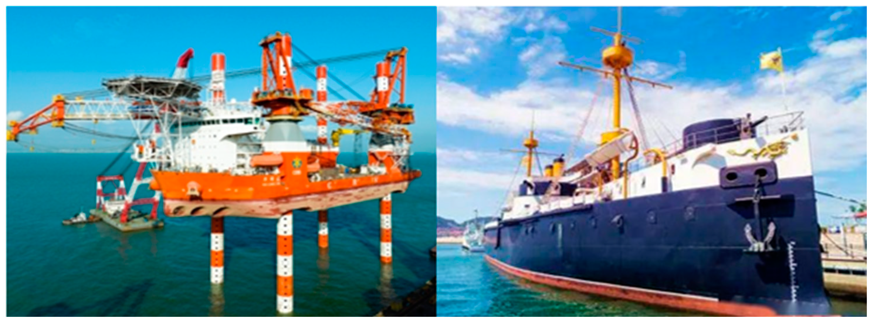
The development of wall-climbing cleaning robots has become an effective solution to this problem. Such robots use ultrahigh-pressure water for cleaning, which can reach the upper part of a cargo hold that is difficult to reach manually, greatly improving cleaning efficiency. In addition, the use of these robots frees the rigging required for artificial high-altitude work and provides safety for workers. The robots are not only environmentally friendly, but also provide an efficient and viable solution for the cleaning and maintenance of the cabins of large cargo ships. Examples of the robots’ operating environments are shown in Figure 1.
Song et al. [3] proposed a wall-climbing robot that can be adsorbed on the wall of a steel structure. Due to the design and optimization of the suction characteristics of the magnetic adsorption component, it has a larger load bearing capacity and more flexible motion ability. Wang et al. [4] proposed an amphibious hexapod robot with composite motor limbs which can move underwater with multiple degrees of freedom and climb stably on slopes of different gradients.
In Japan, Inoue et al. [5] developed a small underwater crawling-type four-swing-arm robot. The robot is equipped with a track motor to drive the track and force arms on both sides of the track, which can also adjust the walking posture of the robot at will.
In 2018, the Central Scientific Laboratory in Nantes, France [6], developed a crawler permanent-magnet wall-climbing robot which can withstand a payload of 100 kg and is mainly used for hull welding and hull surface information scanning. In 2019, La et al. [7], in Australia, developed a four-wheel magnetic wall-climbing robot, which can not only move freely on a magnetic surface, but also carry out data collection and real-time monitoring, mainly using steel structures such as bridges for visual and 3D structural inspection. In 2020, Fukui [8] developed HanGrawler, a wall-climbing robot that can not only travel at a high speed of 0.1 m/s on walls, but also withstand a load of 60 kg.
In 2021, Wang et al. [9] developed a crawler wall-climbing robot, which can adapt to changes in wall curvature by adjusting its movement posture. In 2022, Hunan University and Hebei University of Technology jointly developed a magnetic caterpillar climbing robot applied to large cylindrical walls, which can withstand a payload of 75 kg and climb stably on a cylindrical wall [10]. In 2022, Shanghai Jiao Tong University [11] designed a wall-climbing robot with a double magnetic circuit based on a Halbach array to solve the maintenance problem of large pressure pipelines.
The LBF-300A, produced by Qingdao Luo Bofei Marine Technology Co., LTD., Qingdao City, China, is a piece of cable-controlled underwater detection equipment dedicated to strong current waters. It can be expanded to carry functional equipment, such as robot arms, USBLs, imaging sonars, etc., and has strong scalability and greatly improves the underwater operation capability of equipment [12]. Qi Yuan technology is a company that makes underwater equipment. The Fifish T3 is a small, portable underwater vehicle that is fast and flexible. The T3 is also equipped with a 1-inch zoom wide-angle lens that supports 4K underwater shooting and can transmit content to the surface in real time [13].
Based on the above research results, it can be seen that a complete control system and a strong adsorption walking mechanism are needed to meet the needs of robot hull inspection and other operations.
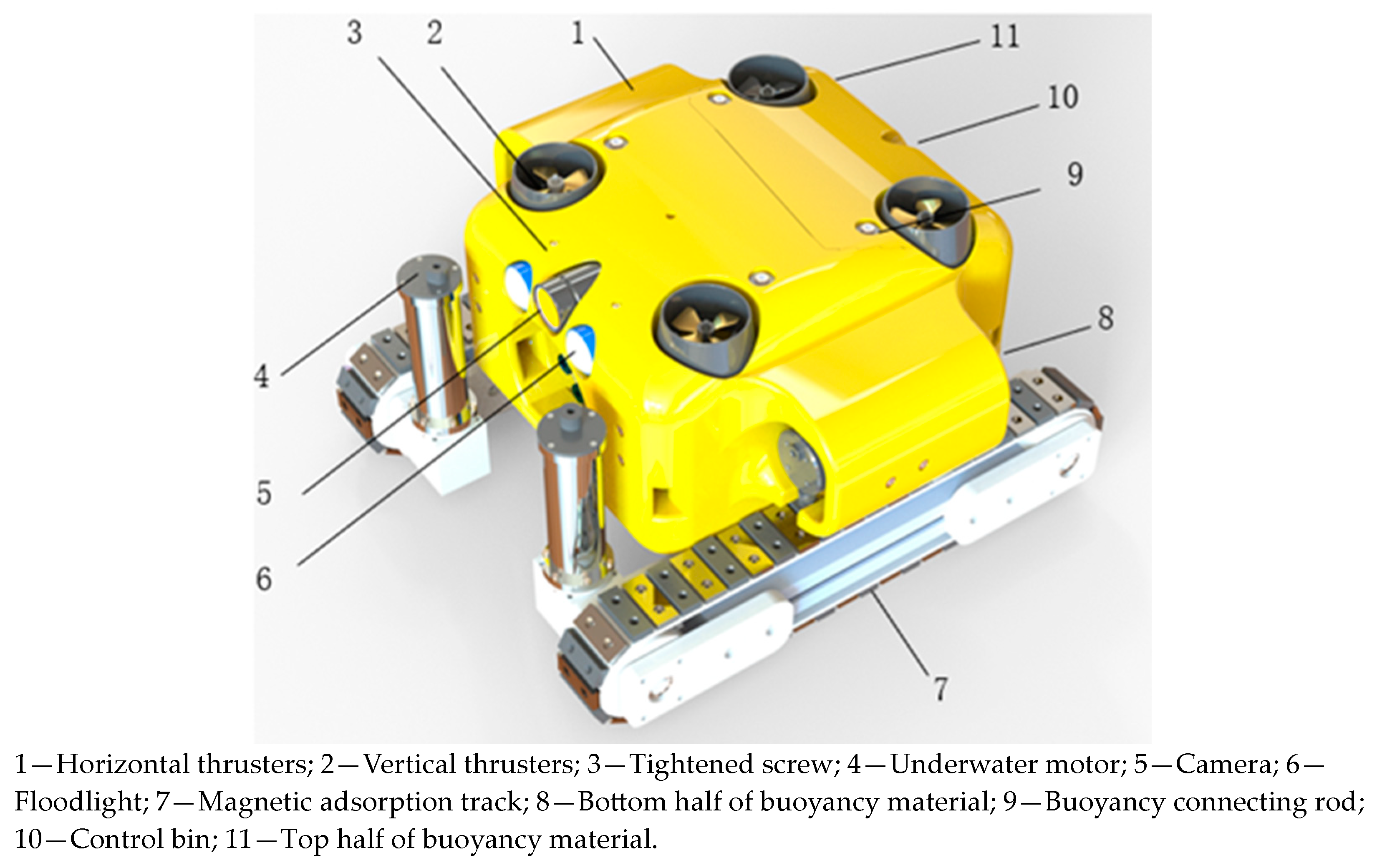
The products of the above research are not perfect for the operation tasks that exist both above and below water. In this paper, an amphibious robot that can operate both above and below the waterline was developed. The designed robot can be moved underwater by thrusters and can also be adsorbed on metal walls by tracks. At the same time, its external volume is designed to make it a small, portable mechanism, which is convenient for manual carrying and placing recovery. By installing a cleaning or detection device on the robot, it can provide an alternative to manual cleaning and detection, improve the detection efficiency and safety of metal wall surfaces on the water and underwater, and achieve the purpose of reducing costs and increasing efficiency.
The amphibious robot is equipped with a high-definition camera and a magnetic adsorption track with adaptive curved surfaces and can fully observe the jacket of an offshore platform above and below the waterline. The underwater depth and bow fixing function of the robot can stabilize the viewing angle and enable ideal shooting. In the detection of jackets of offshore platforms, the amphibious robot can use its underwater motion function to swim near a jacket and adsorb to the jacket through the magnetic adsorption track and crawl on the jacket through the robot track motion function. Due to the strong magnetic adsorption ability of the robot, it can crawl above the water surface for observation. Thus, it can complete the full range of observation functions above and below the water surface.
The design of the robot is equivalent to providing a working platform that can move up and down on the water surface. Based on the existing technology of the robot, it can be appropriately used with other working tools. At present, according to the experimental results of the robot, it can be verified that the robot has a good processing ability for the special working environment of offshore platform jackets.

2. Amphibious Robot System Design

2.1. Establishment of System Structure Model

The portable magnetic adsorption amphibious robot was independently developed in the laboratory. According to the idea of modular parameterization, the robot studied can be divided into a buoyancy mechanism module, a thruster power module, a vision system module, a magnetic adsorption track module, and a control module. The buoyancy mechanism module is made of glass microbead materials, which mainly provide buoyancy for the robot under water. As the power source of the robot’s underwater movement, the propeller power module is used to control the robot’s underwater movement. The function of the vision system module is to observe and locate the target, and two lights are installed on both sides of the module, so that the camera can obtain higher clarity when working in a dark environment [14]. The adsorption unit of the magnetic adsorption track module is fitted with a strong permanent magnet to ensure that the robot is stably adsorbed on the metal wall. The control module is the core module of the robot, and its main role is to provide control signals and power transmission for each component [15].
The robot can not only be controlled near by the handle (1), but also remotely by the remote console (2). The principle of remote control is to use intranet penetration technology, which requires a public IP address as a transit. The remote console sends a Modbus command to the cloud server, and the server forwards the Modbus command to the embedded computer to run the intranet penetration program. Then, the command is forwarded to the robot control board that completes the intranet penetration, and the two sides establish a transparent communication link. The robot system structure is shown in Figure 2.

2.2. Amphibious Robot Work Program Design

The propeller is driven by a DC motor. The propeller adopts the PWM (pulse width modulation) control mode, and the motor speed is controlled by adjusting the duty cycle. The robot’s body is equipped with a total of six thrusters, of which four are vertical thrusters and two are horizontal thrusters. Vertical propellers are installed at the four corners of the robot’s body, which can complete snorkeling, tumbling, and trim movements in the vertical plane. Horizontal propellers are installed on both sides of the robot’s body, which can complete forward and backward movements on the horizontal plane [16].
In a specific implementation scheme, taking an offshore platform pile leg as an example, the working principle can be summarized as follows:
  • Preparations: Install hardware devices on the ground and connect power supplies and cables.
  • Drop the robot into the water using a cable.
  • Water cruise: After the robot has been put into the water, turn on the power and use the remote control to control the robot to achieve water operation.
  • Adsorbing on the pile leg: After getting close to the pile leg, the robot is tilted 90 degrees by the positive and negative rotation of the four vertical thrusters, and then the vertical thruster steering and rotational speed are adjusted so that it slowly approaches the pile leg until it is successfully adsorbed on it.
  • Wall crawling: After the robot is successfully adsorbed on the pile leg, all thrusters stop working and the robot is driven by an underwater motor to crawl on the pile leg to work and can crawl above the water surface.
  • Disengaging from the pile leg: After the work is completed, the robot runs underwater to activate the vertical thruster to free it from the pile leg.
  • Device recovery: The robot swims back to shore and is retrieved via a cable.
The specific working principle is shown in Figure 3.

2.3. Ontology System Structure Design

The robot’s body structure has a streamlined design, and the plastic buoyancy material acts as the frame, which not only reduces the volume, but also makes the overall structure more compact. The technical parameters of the amphibious robot are shown in Table 1. The shell of the control cabin is cylindrical, the joints are waterproofed by sealing rings, and the cable connectors are watertight. The control cabin is embedded in the middle of the buoyancy material, and the upper and lower halves of the buoyancy material are used to limit the rotation of the cabin body and the freedom of the upward and downward movement of the left and right sides through the coordination of the upper and lower halves of the buoyancy material. The two ends of the buoyancy material are provided with a limited position boss to limit the cabin body’s freedom of moving forward and backward, so the buoyancy material itself can play an all-directional fixed role in the control cabin. The camera and light are embedded in the mounting hole of the buoyancy material and are secured by the upper setting screw. The model structure is shown in Figure 4.

2.4. Control Cabin Structure Design

As the core component of amphibious robots, the control capsule has two common forms: a spherical shell and a cylindrical shell. When the ratios of weight to displacement were determined for the two types of shells, the spherical shell showed the best performance, while that of the cylindrical shell was relatively poor. From the point of view of stress distribution inside the sealed chamber, the film stress of the spherical shell was the most uniform, but the cylindrical shell had an excellent performance in the utilization of internal space. In view of the fact that the actual working depth of the amphibious robot is not more than 100 m, and in order to arrange the electronic components more effectively, it was decided to use the cylindrical shell as the structural form of the control chamber. The general parameters of the control cabin design are shown in Table 2. The outer shell is made of acrylic material, with double O-ring seals and grease to ensure tightness. The control module profile is shown in Figure 5.
The hollow bolt for sealing is installed on the hatch cover, and the hollow bolt is provided with an O-ring groove and a matching sealing nut to meet the sealing requirement and facilitate the peripheral wiring. The sealing method for the control cabin interface is usually “contact sealing”, and the O-type sealing rings are made of corrosion-resistant fluorine rubber material.
The control cabin is equipped with a control board, an electronic governor, an underwater motor drive board, a depth sensor, and a gyroscope. In order to ensure that the robot is not damaged during operation, temperature and humidity sensors and pressure sensors are installed inside the control chamber near the interface, while the control chamber is sealed according to the standard design. When there is a small leak in the cabin, a signal is immediately sent to the ground control console so that the staff can promptly power off and recover the robot. The cabin is made of acrylic plastic, which has the characteristics of high transmittance, low density, and ductile deformation. The performance parameters of the acrylic plastic are shown in Table 3.
In order to ensure the safe operation of the control cabin underwater, a static simulation of the cabin body was analyzed. The applied pressure was 1.5 MPa [17]. Since the two ends of the hatch body are supported by the hatch cover, it was only necessary to impose fixed constraints on the two ends of the hatch body. A cloud diagram of cabin stress and deformation is shown in Figure 6. The maximum deformation area of the cabin body is in the middle part, and the minimum safety factor is greater than 1.5, so the requirements for underwater operation of the robot are met. That is, when the robot is 100 m underwater, the control cabin will not be damaged due to underwater pressure, and the control cabin body will meet the strength requirements.

2.5. Structure Design of Magnetic Adsorption Track System

The structure of the magnetic adsorption track system can be divided into a track frame, a drive module, a walking module, an adsorption module, and other parts [18]. The walking module is mainly composed of two ATN10 synchronous belts, which are installed either side of the track frame. The track length of each side is 1120 mm, the bandwidth is 50 mm, and the thickness of the belt is 5 mm. The belt is made of thermoplastic polyurethane material, and a tensile steel wire core is arranged inside which has high wear and shear resistance.
The adsorption module is mainly composed of a plurality of permanent magnet adsorption units, which are composed of permanent magnets, yoke irons, and rubber blocks. The permanent magnets are installed in the screw holes of the synchronous belt by screws. The yoke irons are arranged under the permanent magnets, and their main function is to converge the magnetic inductivity line generated by the permanent magnets so as to increase their magnetic adsorption performance [19]. In order to stably adsorb on surfaces of different curvatures, spring hinges were adopted to meet the requirements of track adaptive surfaces. The normal state of spring hinges is 90 degrees, and the hinges on both sides are fixed on profiles and robot bodies, and the hinges have spring forces regardless of positive or negative rotation. When a curved surface needs to be adsorbed to, the adsorption force of the magnetic adsorption unit on the metal causes the spring to deform. The angle of hinge opening and closing can be changed to meet the requirements of adaptive surfaces. The structure of the magnetic adsorption track system is shown in Figure 7.

2.6. Underwater Motor Structure Design

The crawling of the amphibious robot depends on the track movement, and the movement of the track is mainly driven by the underwater motor, so the robot needs not only the underwater motor to have high water resistance, but also enough torque when carrying out amphibious operations. The underwater motor uses the deceleration motor, and the motor itself is not waterproof, so the motor needs to be sealed. Different from the static sealing of the control chamber, O-ring sliding seals were adopted because the electric motor drives the transmission shaft to rotate. In order to meet the requirements of underwater dynamic sealing, two layers of O-rings and lubricating resin were designed at the motor transmission shaft, and single-layer O-rings and lubricating resin were also used for static sealing. A section view of the underwater motor structure is shown in Figure 8. The underwater motor is energized to drive the motor shaft to rotate, and the motor shaft drives the matching drive shaft to transmit torque to the outside.
The motor drive board is used to realize the precise control of the motor, which is connected to the IO port of the control board through the signal interface; the power interface is connected to the 24 VDC power supply; and the motor interface is connected to the positive and negative poles of the gear motor. By adjusting the parameters of the PWM pulse waveform, the precise control of motor speed and steering is realized. This process not only simplifies the complexity of motor control, but also improves the stability and reliability of the system. The drive board is provided with two motor interfaces, which are respectively connected to the two underwater motors on the left and right of the track. The signal interface is connected to the control motherboard to receive signal instructions from the control motherboard. Its power interface shares a power line with the control board. A physical picture of the driving board is shown in Figure 9.

3. Amphibious Robot Control System Design

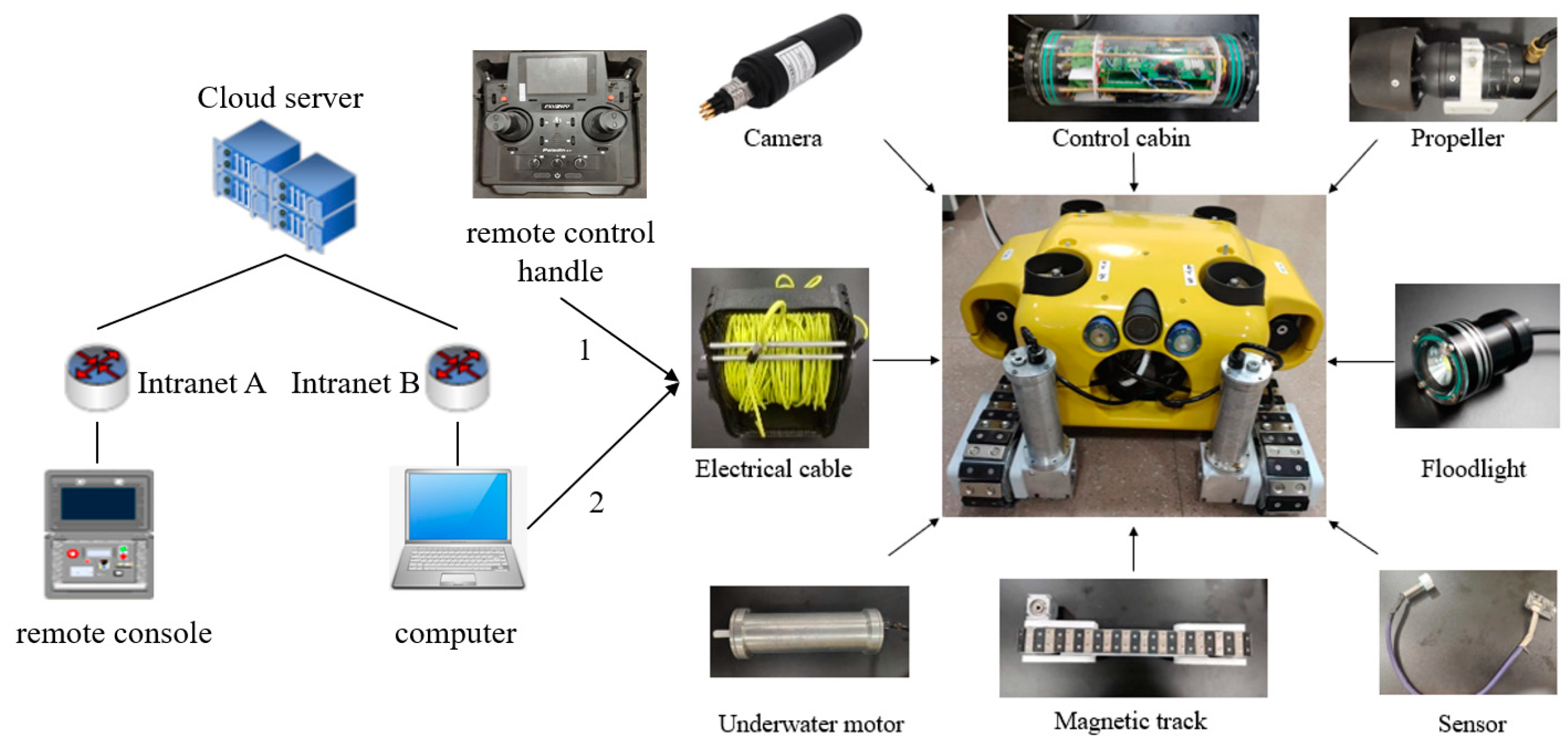
When the robot is subject to local remote control, the robot is controlled wirelessly by the Fuhs remote control, the channel resolution is 4090, and the data output can be PWM/PPM/i-BUS/S.US. The upper layer of the robot control system carries out command control, and the bottom layer carries out motion control. The ground control system includes a control handle, a portable power supply, a ground industrial computer, a cable, a carrier module, etc. The underwater robot body system mainly includes two underwater motors, six brushless DC motor thrusters, two underwater lights, and underwater cameras.

3.1. Hardware Design of Robot Control System

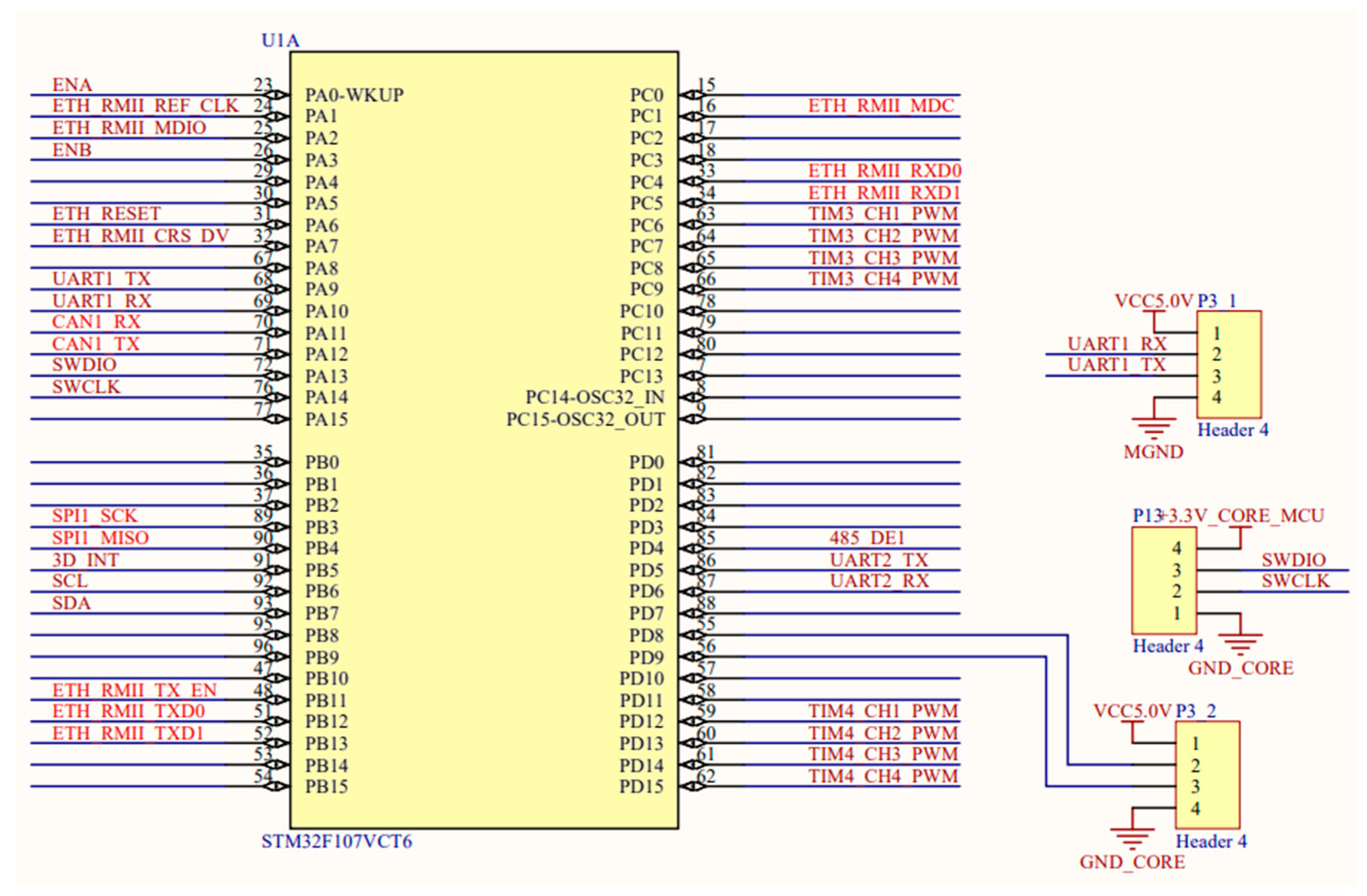
The robot master module uses the STM32F103VCT6 microcontroller, a high-performance ARM Cortex-M3 core operating at 72 MHz, high-speed embedded memory, up to 512 KB of internal flash memory, and up to 64 KB of SRAM, and it is equipped with a variety of peripheral resources, such as a IIC interface, a CAN bus, an SPI interface, a timer, a PWM timer, a 12-bit ADC, an enhanced IO port, etc. Its powerful performance can not only meet the needs of fast response and response stability in the robot control process, but also has the advantages of low power application development and low cost. A circuit diagram of the main control module is shown in Figure 10.
The RS-485 module is a serial communication module whose role is to achieve communication between multiple nodes so that different devices can share a pair of lines for data communication. The Modbus communication protocol based on RS-485 is used in the control motherboard of the upper and lower computer of the portable modular underwater robot. The host computer can not only send control commands to the underwater control motherboard through RS-485, but also read status information, such as serial port data collected by the underwater control motherboard, in real time. A circuit diagram of the RS-485 module is shown in Figure 11.
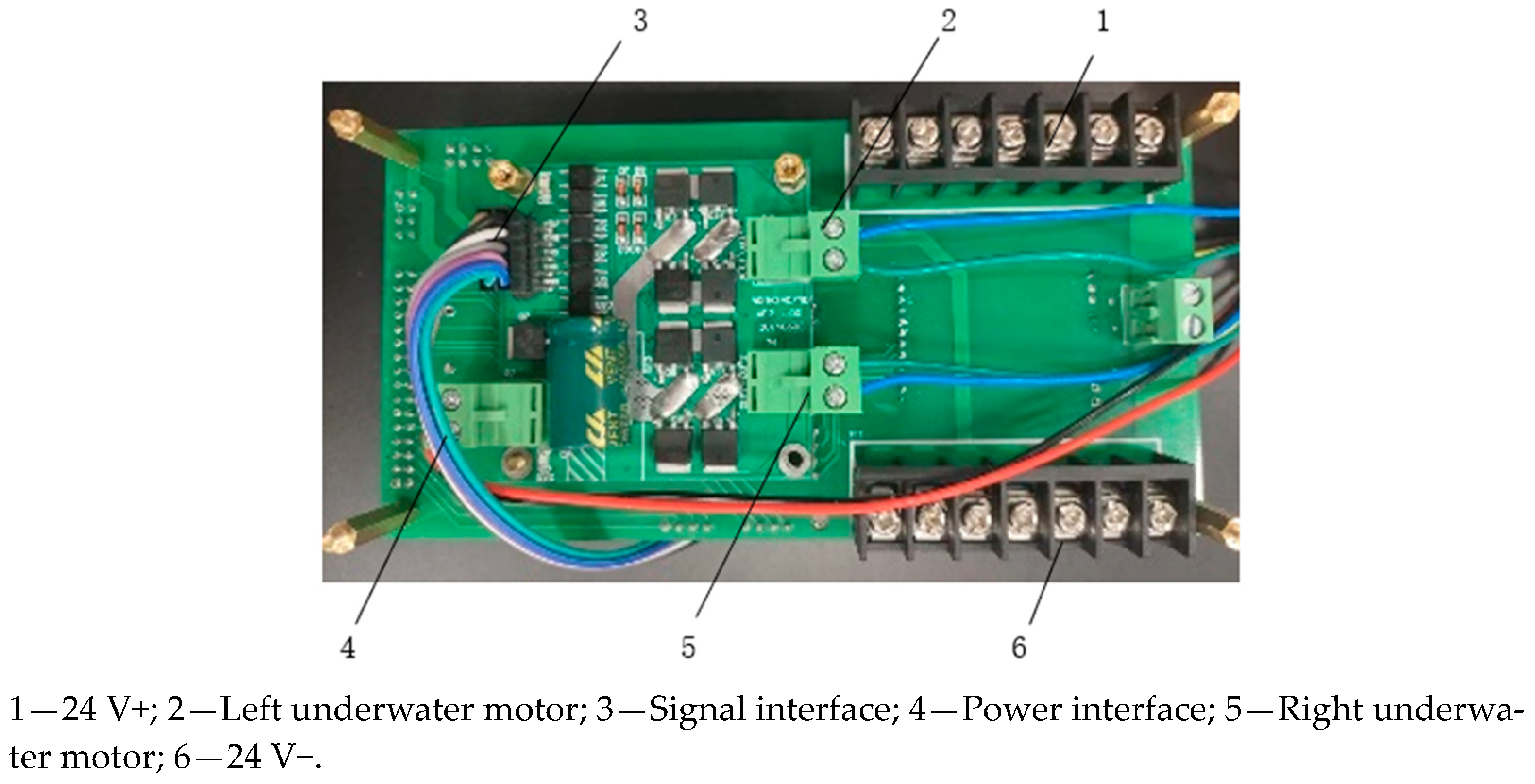
The control motherboard plays an important role in the information interaction and command transmission of the robot in the process of movement. The motherboard integrates the 24 V power supply module for the thruster, the CAN communication module for the thruster, the RS-485 module for the communication between the sensor and the main control chip, and the depth sensor and other interface modules. A physical diagram of the control motherboard is shown in Figure 12.

3.2. Robot Control System Software Design

The robot’s control system software mainly includes a multi-task scheduler based on the RTOS operating system (lower computer) [20], bootloader remote upgrade software, Modbus poll remote control software (the version number is 9.2.2.1343), and a control handle (upper computer). The program of the lower computer is mainly used to read various sensor data and carry out motion control of the robot, while the upper computer can visually display various data collected in the control window [21]. The upper computer and the lower computer can interact with data in real time to facilitate manual control of the robot.
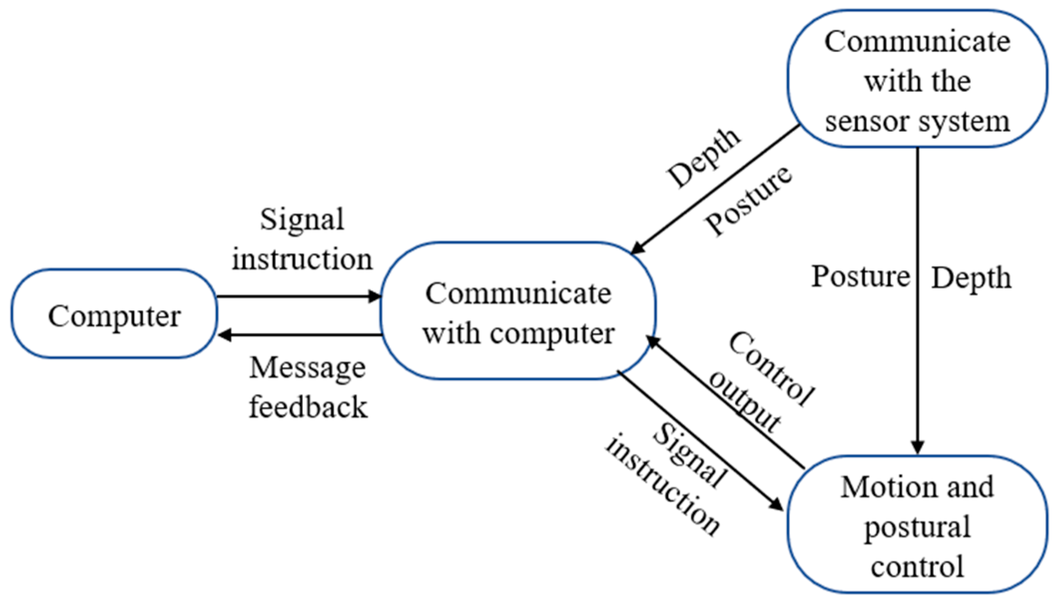
The multi-task scheduling of the robot based on the RTOS operating system can ensure the real-time control and reliability of the system, which can be roughly divided into three threads: the control board to collect sensor system data, the robot motion and attitude control task, and the communication task between the control board and the ground industrial computer. A schematic diagram of multi-task scheduling based on RTOS is shown in Figure 13.
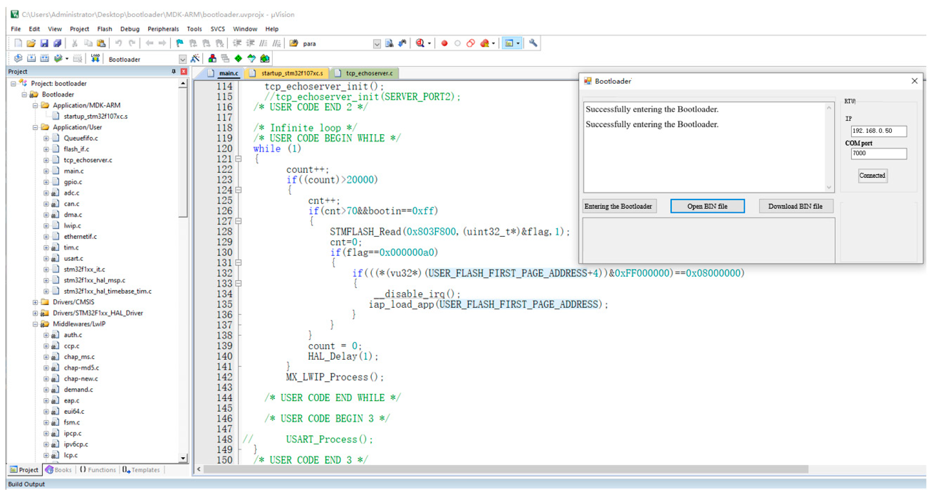
When the control motherboard is installed in the robot control cabin, the electronic bin is repeatedly disassembled to prevent the upgrade of the program in the motherboard, so the bootloader is used to remotely upgrade the robot control motherboard, and the program is downloaded to the chip using the local area network. The bootloader download program interface is shown in Figure 14.
The control board chip is STM32F103VCT6, and the internal flash can be divided into three parts. The bootloader is the first part of the program. Before running the second part of the main program, the bootloader program is entered first. At this time, the bootloader is opened to download the application, and then the IP information of the main control board is input to establish the connection between the control board and the computer. When the current computer receives the command of the remote upgrade application code, the system uses the software to reset and erase the flash area of the remote upgrade application code. Finally, through the bootloader program, the obtained program file of the remote upgrade application is downloaded to the corresponding flash address, and the settings are directly entered into the application after the upgrade is completed. The purpose of remotely updating the program within the control board can be accomplished here.
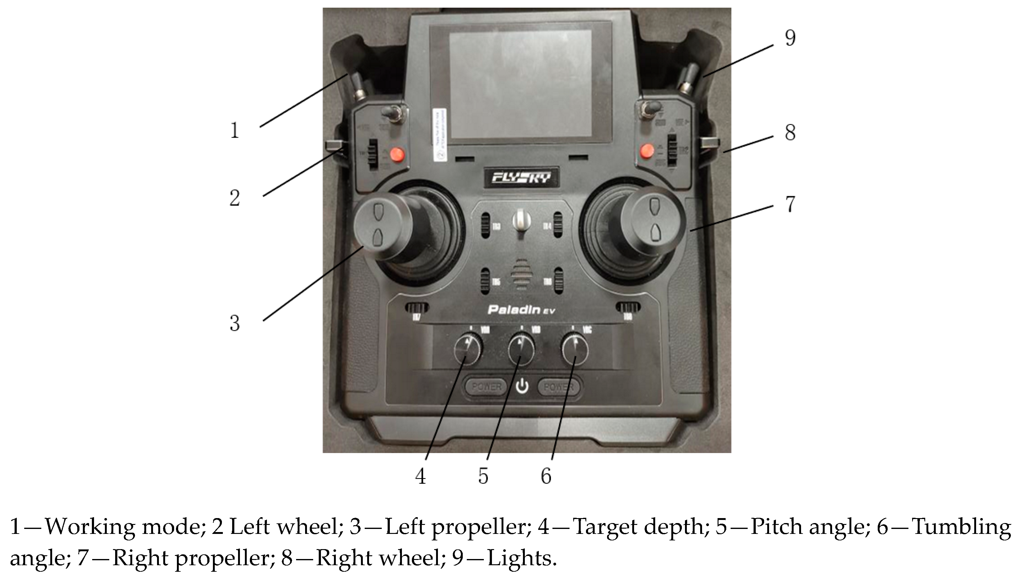
For local remote control, Fusi remote control is used to control the robot in real time, and its control distance can reach more than 300 m, using the AFHDS 3 wireless protocol. The receiver of the remote control is connected to the carrier module on the water, and then the communication signal of the receiver is converted into the TCP/IP protocol of the same network as the power carrier module. A physical picture of the control handle is shown in Figure 15. Modbus is a serial communication protocol [22], which is widely used in industrial automation systems and supports various communication modes, such as traditional RS-232, RS-485, and Ethernet. The Modbus RTU mode is selected according to the amount of communication data [23].

4. Static Analysis of Amphibious Robot

When the robot is crawling on a metal wall, in order to ensure that the robot can meet the safety conditions, it is necessary to identify the factors causing its instability. Next, two main forms of instability will be analyzed: sliding along a wall and longitudinal capsizing. When the robot is about to reach the critical values of the above instability conditions, it will be in danger of escaping from the wall at any time, so it is necessary to analyze and study its instability forms separately [24,25].

4.1. The Robot Slides along the Wall in a Critical State

It is assumed that the metal wall is vertical and there is no depression, and each magnetic adsorption unit produces a uniform adsorption force. The mechanical model of the vertical wall of the robot is shown in Figure 16. M is the robot’s center of mass; G is the robot’s weight; H is the distance between the metal wall and the robot’s center of mass; L is the length of the magnetic adsorption unit touching the metal wall; f is the friction force on the unilateral magnetic adsorption track; Fa is the adsorption force generated by the magnetic adsorption unit; k represents the number of unilateral magnetic adsorption tracks adsorbed on the metal wall; Faj represents the adsorption force of the j-th magnetic adsorption unit of the unilateral magnetic adsorption track on the metal wall, where j = (1,2,… k); and Fb is the supporting force of the metal wall on the magnetic adsorption unit.
Since the robot is in a static state, in order to prevent the robot from sliding, the static friction force should not be less than the robot’s gravity, and for the unilateral magnetic adsorption track, the following conditions apply:
{ j = 1 k F a j = j = 1 k F b j f = G 2 f μ j = 1 k F b j
where μ is the coefficient of static friction.
Since each magnetic adsorption unit produces a uniform adsorption force and the magnetic forces are equal, the following condition obtains:
F a = F a 1 = F a j = F a k
By combining Equations (1) and (2), we can obtain the following:
μ k F a G 2
Then, the adsorption force conditions that the magnetic adsorption unit needs to meet are as follows:
F a G 2 k μ

4.2. The Robot Is in a Critical State of Longitudinal Overturning

Since the robot magnetic adsorption track uses a synchronization belt structure, the magnetic adsorption unit is fixed to the outer surface of the synchronization belt, and the flexible mechanism of the synchronization belt cannot transfer bending moments, so the overturning moment (MG) generated by the robot’s own weight should be borne by the anti-overturning moment generated by the first magnetic adsorption unit. Therefore, as long as the top magnetic adsorption unit meets the conditions of the anti-overturning moment, the robot will not overturn.
Assuming that the robot reaches the critical state of longitudinal overturning and the supporting force on the metal wall of the top magnetic adsorption unit is 0, the moment at the O point can be obtained:
{ F b 1 = 0 M 0 = ( F a 1 F b 1 ) L H G 2 = 0
The adsorption force on the top magnetic adsorption unit is as follows:
F a 1 = H G 2 L
Therefore, the magnetic adsorption force generated by each magnetic adsorption unit on the magnetic adsorption track is as follows:
F a H G 2 L

4.3. Stability Analysis of Robot Magnetic Adsorption

After the above two common instability state analyses, it can be seen from Equations (4) and (7) that the magnetic suction conditions that the magnetic adsorption unit of the amphibious robot needs to meet are as follows:
F a K max { G 2 k μ , H G 2 L }
where K is the safety factor.
The design parameters of the robot are as follows [17]: G = 250 N, L = 380 mm, H = 112 mm, K = 1.5, k = 10, μ = 0.4. By substituting the above design parameters into Equation (8), the magnetic adsorption forces required by the magnetic adsorption unit can be obtained as follows: the adsorption forces in sliding along the wall: F a 46.86   N ; the longitudinal overturning adsorption force: F a 55.26   N .
In summary, the magnetic adsorption unit only needs to meet F a 55.26   N . The amphibious robot can be stably adsorbed on the metal wall in the air.

4.4. Selection of Permanent Magnets

After consulting the information, it was decided to use NdFeB N52 as the permanent magnet material. NdFeB, as a kind of permanent magnet material with strong magnetic adsorption properties, not only has a high magnetic energy product and coercivity, but also has a low price [26,27]. The basic parameters are shown in Table 4.
NdFeB uses high-quality rare earth raw materials, which are hard and brittle and fragile; in order to avoid collision, the design rubber block is 1 mm higher than the permanent magnets to protect them. Considering the width of the air gap, magnetic simulation software was used to calculate that a punched permanent magnet with a size of size of 50 × 20 × 5 mm can produce a 91.45 N adsorption force. Therefore, the N52 permanent magnet selected is sufficient to provide the adsorption force required for the robot to adsorb on a vertical metal wall. The magnetic sensing line of the permanent magnet adsorption unit is shown in Figure 17. The upper right corner is the size of the magnetic adsorption force generated, and the cloud image from top to bottom shows the yoke iron, the permanent magnet, and the metal wall.

5. Dynamic Modeling and Motion Simulation of Amphibious Robot

5.1. Robot Motion Model Building

The robot coordinate system diagram is shown in Figure 18. In order to better control the underwater motion of the robot, it was necessary to establish the underwater motion equation for the amphibious robot. In general, the center of gravity (G ( x g , y g , z g ) ) of the robot and the origin (O) of the robot coordinate system are not concentric, and the resultant motion equation of the amphibious robot with six degrees of freedom can be derived when the robot is regarded as a rigid body.
{ X = m [ u ˙ v r + w q x g ( q 2 + r 2 ) + y g ( p q r ˙ ) + z g ( p r + q ˙ ) ] Y = m [ v ˙ w p + u r y g ( p 2 + r 2 ) + z g ( q r p ˙ ) + x g ( q p + r ˙ ) ] Z = m [ w ˙ u q + v p z g ( q 2 + p 2 ) + x g ( r p q ˙ ) + y g ( r q + p ˙ ) ] K = I x p ˙ + ( I z I y ) q r + m [ y g ( w ˙ + v p u q ) z g ( v ˙ + u r w p ) ] M = I y q ˙ + ( I x I z ) r p + m [ z g ( u ˙ + w q v r ) x g ( w ˙ + v p u q ) ] N = I z r ˙ + ( I y I x ) p q + m [ x g ( v ˙ + u r w p ) y g ( u ˙ + w q v r ) ]
where v = [ u v w p q r ] T is the velocity vector defined in the moving coordinate system and the components correspond to longitudinal velocity, transverse velocity, float velocity, roll angular velocity, pitch velocity, and course angular velocity, respectively; m stands for the amphibious robot’s mass; I x , I y , I z , is the moment of inertia of the amphibious robot on the three coordinate axes; and K , M , N is the moment of the amphibious robot’s force.
The amphibious robot is a nonlinear system, and its movement in water is mainly affected by hydrodynamic force ( F w ), floatage ( B ), gravity ( G ), thruster thrust ( T i ), and cable force ( F l ). The external force on an amphibious robot in water can be expressed as follows:
F = F w + B + G + i = 1 n T i + F l
The amphibious robot uses a zero-buoyancy cable, and the cable force can be ignored.
The calculation of thruster thrust needs to consider the arrangement of the thruster. As shown in Figure 19, there are four vertical thrusters distributed with symmetrical origins. They are respectively represented by T 1 , T 2 , T 3 , T 4 , and the two horizontal thrusters that are symmetrical to each other are respectively represented by T 5 , T 6 .
The thruster thrust formula is as follows:
T = K T ρ D 4 n 2
The thrust torque formula is as follows:
M T = K Q ρ D 5 n 2
where ρ is the water density, n is the propeller speed, D is the airscrew diameter, K T is the thrust coefficient, and K Q is the moment coefficient.
Vertical motion is powered by four vertical thrusters, which provide opposite thrust by controlling the direction of rotation of the propeller. The thrust and torque formulas for vertical motion are as follows:
[ T M ] = [ i = 1 4 T i i = 1 4 M i ] = [ 0 0 T 1 + T 2 + T 3 + T 4 l 1 ( T 1 T 2 + T 3 T 4 ) l 1 ( T 1 + T 2 T 3 T 4 ) 0 ]
The horizontal motion is powered by two horizontal thrusters with the following thrust and torque formulas:
[ T M ] = [ i = 1 2 T i i = 1 2 M i ] = [ T 5 + T 6 0 0 0 0 l 2 ( T 5 T 6 ) ]
In order to simplify the problem, the kinematic coupling between the mutual vertical planes is ignored, and it is assumed that the robot only moves in the horizontal plane or vertical plane direction when carrying out underwater operations, that is, the robot center of gravity (G) will not move synchronously in the two mutual vertical planes. At the same time, considering that the center of gravity of the robot coincides with the origin (O) of the moving coordinate system, the space motion equation of the robot in the horizontal plane and the vertical plane can be simplified as follows:
Horizontal movement
X = m ( u ˙ v r ) Y = m ( v ˙ + u r ) N = I z r ˙
Vertical movement
X = m ( u ˙ + w q ) Z = m ( w ˙ u q ) M = I y q ˙

5.2. Robot Motion Experiment Simulation

The amphibious robot’s operating environment is very complex, so in order to achieve accurate control of the robot, it was necessary to design a closed-loop control system and carry out a system simulation experiment.
(1) Propulsion system transfer function
Under normal circumstances, the propeller motor can be simplified into a first-order inertia link, and the transfer function can be expressed as follows:
G p ( s ) = K p T P s + 1
where K p is the transfer coefficient of the motor and T p is the time constant of the motor. As a nonlinear system, the thruster needs to be linearized. As can be seen from the thruster thrust formula (Equation (11)), where all parameters are constant, it can be written as follows:
T = C n
C = 2 K T ρ D 4 n 0 , where n 0 is the rated speed of the motor, from which the transfer function of speed and thrust can be derived:
G T ( s ) = T ( s ) n ( s ) = C
(2) Transfer function of motion system
Fixed depth motion control model: the robot only carries out fixed depth motion in the vertical plane, and its motion equation is as follows:
( m + Q w ˙ ) w ˙ = C z w + T z
where Q w ˙ is an additional quality, C z is a dimensionless coefficient of the z-axis, and T z is the vertical force.
According to the relationship between the depth value ( Z h ) and the linear velocity ( w ), Z ˙ h = w , Z ¨ h = w ˙ , the transfer function between the depth of the robot and the thrust received can be derived as follows:
G w ( s ) = Z h ( s ) T z ( s ) = 1 ( m + Q w ) s 2 C Z s
Fixed heading motion control model: the robot only rotates on the horizontal plane, and its heading motion equation is as follows:
M T M R M r ˙ = I z r ˙
The total pushing torque in the horizontal direction is as follows:
M T = 2 T l 2 = 2 K T ρ D 4 n 2 l 2
The blocked torque of the robot is as follows:
M R = 0.5 N r ρ S r 2
where N r is the resistance coefficient when the robot alters its course and S is the characteristic area.
The moment of inertia is calculated as follows:
M r ˙ = Q r r ˙
where Q r is the added mass.
r ˙ is represented by ψ ¨ , which is sorted and simplified as follows:
M T I z + Q r = ψ ¨
where ψ is the heading angle.
The transfer function of the turning motion can be obtained by using the Laplace transform:
G r ( s ) = ψ ( s ) M T ( s ) = 1 s 2 ( Q r + I z )
Through actual measurements, estimation, and reference to the relevant literature [17], the values of each part of the parameters can be determined: S = 0.24   m 2 , K p = 120 , T p = 0.6   s , C = 0.017 , C z = 1.31 , N r = 0.25 , N r ˙ = 0.08 I z , I z = 0.94   kg m 2 , I y = 0.78   kg m 2 . They are substituted into the transfer function of the fixed depth and fixed bow motion control system:
Transfer function of fixed depth motion control system:
G H = G p ( s ) G T ( s ) G w ( s ) = 1 7.371 s 3 + 12.671 s 2 + 0.642 s
Fixed heading motion control system transfer function:
G ψ = G p ( s ) G T ( s ) G r ( s ) = 1 0.299 s 3 + 0.498 s 2
The control system was introduced into the PID controller, and then modeling and simulations were carried out to obtain the simulation curves for the fixed depth and fixed bow conditions, as shown in Figure 20 and Figure 21, respectively.
It can be seen from the simulation curve that in the fixed depth simulation process, it takes 6 s from the initial response to the target depth. At the 15th second, the system stabilizes within the target depth range, and the maximum overshoot is 5%. In the course of the fixed heading simulation, it takes 6 s from the initial response to the target heading angle. In the 11th second, the system stabilizes within the range of the target heading angle, and the maximum overshoot is 7%. The control system for depth fixing and heading fixing can reach the target value with a fast speed and low overshoot, which can meet the task requirements for depth fixing and heading fixing.

6. Amphibious Robot Experiment

In order to verify the rationality of an amphibious robot design, two groups of experiments need to be designed: 1. to determine the robot’s motion and attitude control effect under water; 2. to determine that the robot stably adsorbs on metal walls above and below the waterline.

6.1. Robot Underwater Motion Control Test

Robot underwater motion control can also directly modify the working mode through the Modbus poll control software to complete specific work tasks, such as depth setting, cruise, etc. The data collected by gyroscope can be displayed in real time by the Modbus poll software. An experimental diagram of robot movement and underwater shooting is shown in Figure 22. The robot can move forward and backward, turn, float up and dive down, and flip over normally.
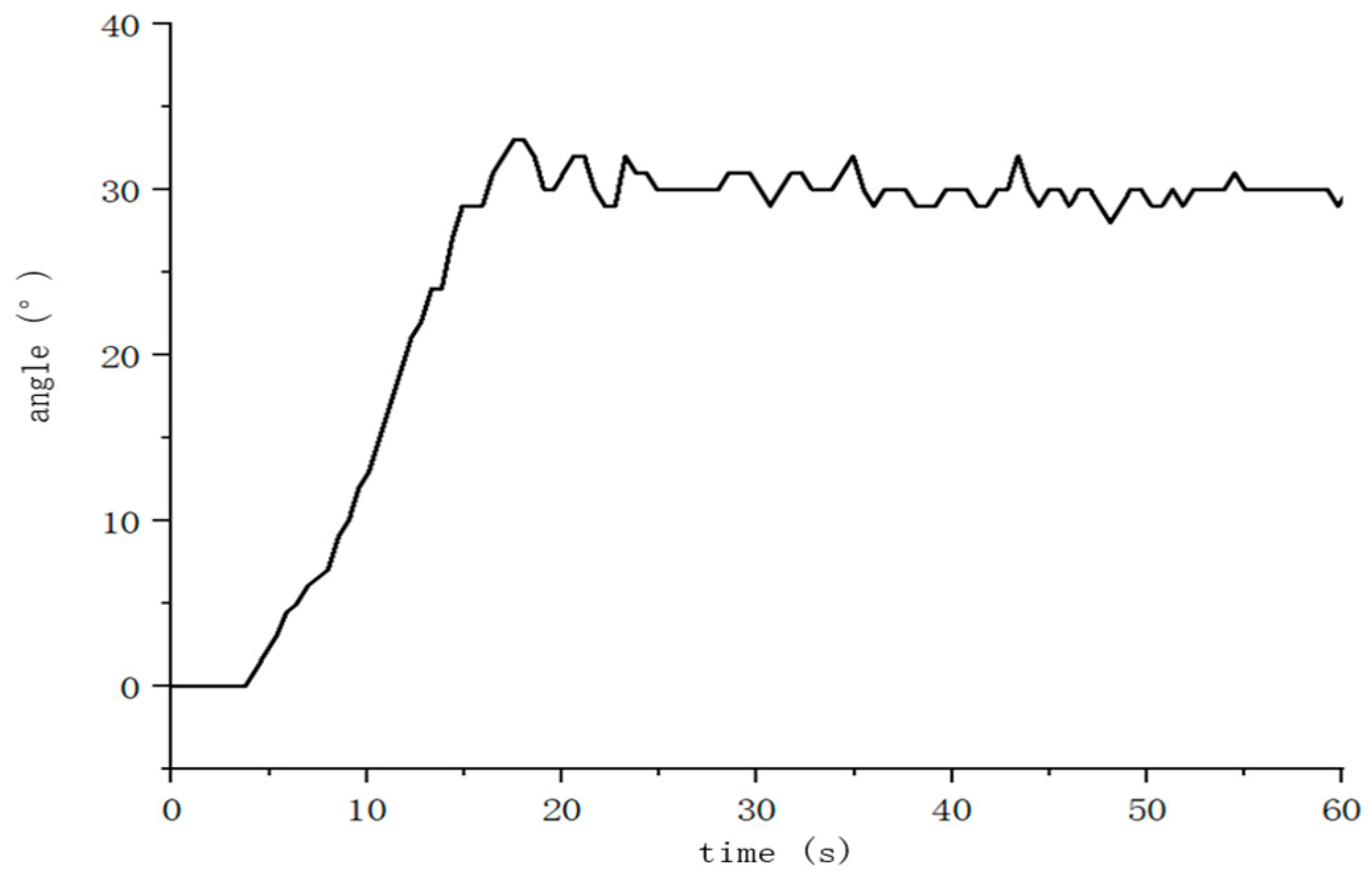
In order to test the real control performance of the robot control system, a fixed depth of 0.5 m and a fixed bow of 30° were set for control tests. The depth control uses the depth sensor, and the heading control uses the gyroscope to collect and feedback information. The change curves of the two experimental angles are shown in Figure 23 and Figure 24.
In the depth control experiment, when the robot was suspended in water, the initial depth was 0 m. After waiting for 4 s, the robot was controlled to dive, and the diving depth gradually increased until it reached 0.5 m, and then it stably hovered in the water. The response time of the robot was short and there was no big jitter, and the control effect was good.
In the constant heading control experiment, the initial heading angle of the robot was adjusted to 0°, and the robot was controlled to turn after 4 s. The heading angle gradually increased, and the robot stably hovered in the water after reaching 30°. During the whole movement, the robot ran smoothly. The above experimental results show that the designed robot attitude control system has good control performance.
By comparing the experimental data with the simulation results, it can be seen that the experimental results are in good agreement with the simulated results of the calculated transfer function, and the time from receiving the instruction to making the response action to reaching the target result is about 13 s, and the overshoot is low. The transfer function shows the feasibility of the robot control system, and the experimental data demonstrate the correctness of the transfer function.

6.2. Robot Wall-Climbing Test

Considering actual situations, the diameter of the jacket of an offshore platform is generally relatively large. Due to the small size of the amphibious robot designed, the robot can be regarded as having a curved surface with an infinite diameter, that is, the robot action scene is regarded as a plane. However, due to the limitations of the conditions, the simulation experiment for the robot’s function was carried out in a pool. However, such experiments can still normally reflect the practicality of amphibious robot functions.
The amphibious robot was tested on a metal wall consisting of Q235 material and with a thickness of 5 mm to check its climbing performance. The wall-climbing process of the robot is shown in Figure 25. During the test, the robot could stably adsorb on the metal wall and successfully complete basic movements, such as forward, backward, and turning movements, meeting the test requirements.

7. Conclusions

An amphibious robot has been developed that can perform tasks above and below the waterline. The robot model was established, then a static analysis was carried out, and suitable permanent magnets were selected by magnetic simulation software. The robot can also adapt to metal walls and climb stably. With STM32 as the core, the integrated control system of the robot was established, and the underwater dynamics of the robot were modeled. The experiment proves that the amphibious robot can realize attitude and motion control in water, and its control system can satisfy the basic control ability. The amphibious robot has realized the requirement of working above and below the waterline with metal walls, and the results show that it can be used in amphibious operations, such as those involving pile legs of offshore platforms and outer walls of ships, providing great help in underwater safety operations.
At present, there are few amphibious robots capable of operating above and below the waterline, and the portable magnetic adsorption amphibious robot has the advantage of crawling on metal walls compared with the underwater robots on the market, and it can be installed with different operations in later stages for fully specified tasks. However, compared with more mature robots, the amphibious robot’s control system needs to be optimized, and there are some problems, such as the long control reaction time and deviation with respect to accurate positioning. For the design, in order to further optimize the frame structure, it is necessary to reduce the center of gravity of the robot, reduce the volume and weight, effectively reduce the force of water flow on the robot, and give full play to the propulsion ability of the propeller. In addition, it is also necessary to adjust the layout of the buoyancy material to ensure that the center of gravity of the body and the center of buoyancy are on the same axis as far as possible when the robot climbs a wall vertically.
The portable magnetic adsorption amphibious robot not only has the ability to work underwater, but can also work on metal walls on the water, and the amphibious robot has the ability to automatically adapt to curved surfaces and can stably crawl on most of the curvatures of walls. In the future, based on this amphibious robot, a working robot with a more reasonable structure and a more perfect control system can be designed. For example, the amphibious robot can be used for testing operations on specific occasions by installing a testing mechanism. When a cleaning device is installed, it can be used for cleaning operations on other devices, etc.

Author Contributions

F.R. proposed the idea. B.W. and K.W. referred to the materials and analyzed the feasibility of the study. F.R., J.Z. and B.W. carried out the detailed design of the structure and manufacture of the physical object. J.L. programmed the robot system to enable it. F.R., J.Z. and J.L. designed the experiment. J.Z. produced the pictures in the paper and finished the writing. All authors have read and agreed to the published version of the manuscript.

Funding

Hainan High-tech Project, Intelligent ROV R&D and application technology for integrated inspection operation (ZDYF2023GXJS004); Scientific Research and Technology Development Project of China National Petroleum Corporation, Shoal Intelligent ROV System Development and Support Technology research for jacket Operation (2021DJ2504).

Institutional Review Board Statement

Not applicable.

Informed Consent Statement

Not applicable.

Data Availability Statement

The original contributions presented in the study are included in the article, further inquiries can be directed to the corresponding author.

Conflicts of Interest

Author Kekuan Wang was employed by the company CNPC Engineering Technology Research Company Limited. The remaining authors declare that the research was conducted in the absence of any commercial or financial relationships that could be construed as a potential conflict of interest.

References

  1. Wang, X.; Li, T. Analysis and test of cleaning performance of underwater robot for Wall Cleaning. J. Jilin Univ. (Eng. Technol. Ed.) 2023, 53, 3062–3068. [Google Scholar]
  2. Wang, J.; Zhang, J.; Li, C.; Qin, M. Development and experiment of an autonomous small shallow water underwater pipeline inspection robot. Mach. Des. 2023, 40, 83–87. [Google Scholar]
  3. Song, W.; Jiang, H.; Wang, T.; Gao, Z.; Du, Z.; Zhu, S. Optimal design and Experimental study of Magnetic Adsorption Components for wall-climbing Robot. J. Zhejiang Univ. (Eng. Technol.) 2018, 52, 1837–1844. [Google Scholar]
  4. Wang, Y.; Zhou, S.; Li, Y. Design and Performance Evaluation of amphibious Hexapod Robot. China Mech. Eng. 2022, 33, 2079–2086. [Google Scholar]
  5. Inoue, T.; Takagi, K.; Shiosawa, T. Flipper Type Crawler System for Running on the Irregular Seafloor; IEEE: Piscataway, NJ, USA, 2010. [Google Scholar]
  6. Olivier, K. A Magnetic Climbing Robot to Perform Autonomous Welding in the Shipbuilding Industry. Robot. Comput.-Integr. Manuf. 2018, 53, 178–186. [Google Scholar]
  7. La, H.M.; Dinh, T.H.; Pham, N.H.; Ha, Q.P.; Pham, A.Q. Automated Robotic Monitoring and Inspection of Steel Structures and Bridges. Robotica 2019, 37, 947–967. [Google Scholar] [CrossRef]
  8. Fukui, R.; Yamada, Y.; Mitsudome, K.; Sano, K.; Warisawa, S.I. Han-Grawler: Large-Payload and High-Speed Ceiling Mobile Robot Using Crawler. IEEE Trans. Robot. 2020, 36, 1053–1066. [Google Scholar] [CrossRef]
  9. Wang, Y.; Zhang, X.; Zhang, M.; Sun, L.; Li, M. Self-Compliant Track-Type Wall-Climbing Robot for Variable Curvature Facade. IEEE Access 2021, 10, 51951–51963. [Google Scholar] [CrossRef]
  10. Hu, J. A Magnetic Crawler Wall-Climbing Robot with Capacity of High Payload on the Convex Surface. Robot. Auton. Syst. 2022, 148, 103907. [Google Scholar] [CrossRef]
  11. Zhang, Y.; Guan, E.; Li, P.; Zhao, Y. A Novel Magnetic Circuit Design Method for a Permanent Magnetic Chuck of a Wall-Climbing Robot. Energies 2022, 15, 6653. [Google Scholar] [CrossRef]
  12. Wu, F. Research on hydrostatic pressure Test of underwater Robot. Mech. Electr. Eng. Technol. 2021, 50, 134–137. [Google Scholar]
  13. Duan, L. “FiFish Flying Fish” underwater drone opens the era of personal exploration of the ocean. Comput. Netw. 2016, 42, 34–35. [Google Scholar]
  14. Ye, L.; Wu, D.; Xie, C. Inspection robot System for underwater structure monitoring. China Marit. Transp. 2023, 8, 94–96. [Google Scholar]
  15. Ren, F.; Fan, Y. Development of lateral depth determination control based on Small amphibious Robot. Electron. Meas. Technol. 2021, 44, 77–84. [Google Scholar]
  16. Wang, C.; Yin, H.; Lin, X.; Lai, S. Review on propulsion system of underwater vehicle. Pearl River Transp. 2019, 14, 84–85. [Google Scholar]
  17. Li, M. Hydrodynamic Numerical Calculation and Characteristic Analysis of ROV for Jacket Inspection; Northeast Petroleum University: Daqing, China, 2018. [Google Scholar]
  18. Zhao, F.; Yao, Z.; Ling, H.; Wang, Q. Design and Experiment of Crawler Wall-climbing Robot for Rust Removal. Mach. Des. Res. 2023, 39, 29–33. [Google Scholar]
  19. Qiu, J.; Wang, M.; Ying, F.; Yang, L.; Guo, Y. Structure Design and Implementation of Micro-Magnetic Adsorption wall-climbing Robot. J. Mach. Des. 2023, 40, 1–8. [Google Scholar]
  20. Li, Z. Design and Research of Magnetic Adsorption Cleaning Robot System for Wind Power Tower; Shijiazhuang Railway University: Shijiazhuang, China, 2023. [Google Scholar]
  21. Mistry, J.; Naylor, M.; Woodocock, J. Adapting Free-RTOS for multicores: An experience report. Softw. Pract. Exp. 2014, 44, 1129–1154. [Google Scholar] [CrossRef]
  22. Song, S.; Kim, J.; Kim, T.; Song, Y.W.; Yu, S.C. Development of a Biomimetic Underwater Robot for Bottom Inspection of Marine Structures. Int. J. Control Autom. Syst. 2023, 21, 4041–4056. [Google Scholar] [CrossRef]
  23. Wu, X.; Wang, X.; Zhou, J. Computer Monitoring System of sluice Gate based on Modbus Communication Protocol. Comput. Eng. 2005, 31, 195–197. [Google Scholar]
  24. Cheng, X.; Wang, H. Analysis of key contents of Modbus-RTU protocol and its application in Intelligent electrical Appliances. Electr. Appl. Energy Effic. Manag. Technol. 2010, 1, 23–25. [Google Scholar]
  25. Tummala, R.L.; Mukherjee, R.; Xi, N.; Aslam, D.; Dulimarta, H.; Xiao, J.; Mark, M.; Dangi, G. Climbing the walls robots. IEEE Robot. Autom. Mag. 2002, 9, 10–19. [Google Scholar] [CrossRef]
  26. Wu, J.; Liu, D.; Wang, X.; Lin, X.; Liu, H. Hydrodynamic analysis and experimental research of underwater robot for ship wall cleaning. Ship Eng. 2018, 40, 91–97. [Google Scholar]
  27. Yang, X.; Zhang, X.; Zhang, M. Mechanical Analysis and Performance Test of Metal Wall Climbing Robot. Manuf. Autom. 2022, 44, 36–39. [Google Scholar]
Figure 1. Robot operating environments.
Applsci 14 02820 g001
Figure 2. Amphibious robot system structure.
Applsci 14 02820 g002
Figure 3. Working principle diagram.
Applsci 14 02820 g003
Figure 4. Model structure.
Applsci 14 02820 g004
Figure 5. Control module profile.
Applsci 14 02820 g005
Figure 6. Cabin stress and deformation cloud map. (a) Stress. (b) Deformation results.
Applsci 14 02820 g006
Figure 7. Structure of magnetic adsorption track system.
Applsci 14 02820 g007
Figure 8. Section view of underwater motor structure.
Applsci 14 02820 g008
Figure 9. Real picture of the drive board.
Applsci 14 02820 g009
Figure 10. Main control module circuit diagram.
Applsci 14 02820 g010
Figure 11. Circuit diagram of RS-485 module.
Applsci 14 02820 g011
Figure 12. Control motherboard physical picture.
Applsci 14 02820 g012
Figure 13. Schematic diagram of multi-task scheduling based on RTOS.
Applsci 14 02820 g013
Figure 14. Bootloader download program interface.
Applsci 14 02820 g014
Figure 15. Control handle physical picture.
Applsci 14 02820 g015
Figure 16. Mechanical model of vertical wall of robot.
Applsci 14 02820 g016
Figure 17. Magnetic inductance line of permanent magnet adsorption unit.
Applsci 14 02820 g017
Figure 18. Schematic diagram of robot coordinate system.
Applsci 14 02820 g018
Figure 19. Layout of push machine.
Applsci 14 02820 g019
Figure 20. Simulation curve with fixed depth of 0.5 m.
Applsci 14 02820 g020
Figure 21. The 30° fixed bow simulation curve.
Applsci 14 02820 g021
Figure 22. Experimental diagram of robot movement and underwater shooting. (a) Hovering in water. (b) Sinking condition. (c) Steering condition. (d) Underwater shooting.
Applsci 14 02820 g022
Figure 23. Depth change curve.
Applsci 14 02820 g023
Figure 24. Changing curve of heading angle.
Applsci 14 02820 g024
Figure 25. The process of the robot climbing the wall.
Applsci 14 02820 g025
Table 1. Technical parameters of amphibious robot.
IndexData
Size520 mm × 490 mm × 300 mm
Quality25 kg
Maximum operating
water depth
100 m
Nominal voltage24 V
Maximum wall
climbing speed
4.12 m/min
Table 2. Control cabin general parameters.
IndexData
Quality2 kg
Length280 mm
External diameter110 mm
Pipe thickness4 mm
Volume of displacement2.66 L
Number of peripheral connections15
Table 3. Acrylic plastic performance parameters.
Density (kg/m3)Elasticity Modulus (MPa)Yield Strength (MPa)Poisson
Ratio
1180227077.20.4
Table 4. Performance parameters of NdFeB N52.
Remanent Magnetic
Induction
( B r / m T )
Coercivity
( H c / ( k A × m 1 ) )
Maximum Magnetic Energy Product
( B k m a x / ( k A × m 1 ) )
Operating Temperature
( T w / ° C )
1430–1480828–907398–422<60
Disclaimer/Publisher’s Note: The statements, opinions and data contained in all publications are solely those of the individual author(s) and contributor(s) and not of MDPI and/or the editor(s). MDPI and/or the editor(s) disclaim responsibility for any injury to people or property resulting from any ideas, methods, instructions or products referred to in the content.

