Article

A Laser-Induced Breakdown Spectroscopy (LIBS) Instrument for In-Situ Exploration with the DLR Lightweight Rover Unit (LRU)

1
German Aerospace Center (DLR), Institute of Optical Sensor Systems, Rutherfordstrasse 2, 12489 Berlin, Germany
2
German Aerospace Center (DLR), Institute of Robotics and Mechatronics, Münchner Str. 20, 82234 Weßling, Germany
*
Authors to whom correspondence should be addressed.
Appl. Sci. 2024, 14(6), 2467; https://doi.org/10.3390/app14062467
Submission received: 1 December 2023 / Revised: 16 January 2024 / Accepted: 29 January 2024 / Published: 14 March 2024
(This article belongs to the Section Optics and Lasers)

Abstract

:
In the framework of the Helmholtz ARCHES project, a multitude of robots, including rovers and drones, were prepared for the autonomous exploration of a test site at the foothills of Mt. Etna, Sicily—a terrain resembling extraterrestrial locations such as the Moon. To expand the suite of tools and sensors available for the exploration and investigation of the test site, we developed a laser-induced breakdown spectroscopy (LIBS) instrument for the geochemical analysis of local geological samples. In alignment with the mission scenario, this instrument is housed in a modular payload box that can be attached to the robotic arm of the Lightweight Rover Unit 2 (LRU2), allowing the rover to use the instrument autonomously in the field. A compact Nd:YAG laser is utilized for material ablation, generating a micro-plasma that is subsequently analyzed with a small fiber-coupled spectrometer. A single-board computer controls the LIBS hardware components for data acquisition. In this study, we provide details of the ARCHES LIBS instrument implementation, report on preceding laboratory tests where the LRU2 operated the LIBS module for the first time, and showcase the results obtained during the successful ARCHES space analogue demonstration mission campaign in summer 2022 in Sicily.

1. Introduction

The elemental analysis technique Laser-Induced Breakdown Spectroscopy (LIBS) is particularly well suited for robotic in-situ exploration. It allows for rapid data acquisition with optical access only, eliminating the need for sample preparation. LIBS can be applied remotely over several meters and utilized by robots in terrains that are inaccessible or dangerous for humans. To conduct a LIBS measurement, a pulsed laser beam is focused onto the sample’s surface. With sufficiently high irradiance, a small amount of material is ablated and excited into a micro-plasma [1]. The light emitted by the plasma is then analyzed with a spectrometer, providing information about the elemental composition.
LIBS is utilized for in-situ geochemical analysis of the Martian surface by all currently active rovers on our neighboring planet. The first ever LIBS instrument for space exploration is the ChemCam instrument onboard NASA’s Mars Science Laboratory rover “Curiosity”, which has successfully collected LIBS data from Gale Crater since the rover’s landing in 2012 [2,3,4]. SuperCam, the enhanced follow-up of the ChemCam instrument, features additional techniques such as reflectance spectroscopy in the visible and near-infrared wavelength range, as well as time-resolved Raman and luminescence spectroscopy [5,6]. SuperCam, the second LIBS instrument, arrived on Mars in February 2021 and has since been collecting data from Jezero Crater as a highly versatile payload on NASA’s Perseverance Mars 2020 rover. The third LIBS instrument on a rover for Mars is MarSCoDe, developed by the Chinese space agency CNSA, closely following the ChemCam design [7,8]. MarSCoDe arrived on Mars later in 2021 and collected LIBS data until late 2022. All three instruments were designed to allow the analysis of samples at several meters distance from their respective spacecraft.
Another LIBS instrument for space exploration was developed as a payload for the small rover of India’s Chandrayaan-2 mission, aimed at exploring the lunar surface [9,10]. Although the lander experienced a failed soft landing in 2019, a second attempt in 2023 was reported as successful. The Chandrayaan LIBS was designed to be lightweight, with no focusing system, to measure the lunar regolith below the rover’s chassis at a constant distance of 0.2 m. Other LIBS instruments have been proposed for space missions and the prospects of LIBS systems for different planetary bodies have been studied [11,12,13,14,15].
With a LIBS instrument configured for remote sampling with optical access only, a substantial amount of data can be collected as is evident from ChemCam [4] and SuperCam [16]. ChemCam obtained approximately 930,000 LIBS spectra from the surface of Mars over the course of 3700 sols (i.e., Martian days since the rover’s landing) [17] and is still used almost on a daily basis. While a configuration on the rover’s mast offers advantages in terms of optical access to targets at various distances up to several meters around the rover, the necessity of providing sufficient irradiance at these distances requires a powerful laser and a telescopic autofocus system. This requirement makes the instruments much larger and heavier than fixed-focus systems that measure at closer distances. ChemCam, SuperCam, and MarSCoDe weigh approximately 10 kg.
For the purpose of the ARCHES project, our goal was to enhance the modular instrument and tool suite of the DLR Lightweight Rover Unit 2 (LRU2). LRU2 is equipped with a robotic arm, enabling the rover to utilize various tools and instruments in the field [18,19,20]. Given the arm’s capability to precisely move the payload box with the LIBS instrument to the point of interest on a rock, we opted for a fixed-focus approach, where the instrument is placed in direct contact with the target of interest. This approach allowed us to design a compact and low-mass instrument with a long depth of field. The primary objective of the LIBS module is to analyze geomaterials in the field, contributing to the ongoing efforts in preparing rovers with appropriate instrumentation for the in-situ exploration of solar system bodies [20]. In addition to performing exploration tasks on Earth and beyond, including scouting for specific elements of interest for exploitation, a rover equipped with a LIBS instrument can also carry out automated observation and monitoring tasks. This includes routine measurements of rocks or soils before processing, during treatment, and after treatment [21,22,23]. To the best of our knowledge, no arm-mounted LIBS instrument has been developed for a rover, either for Earth or extraterrestrial applications. However, such a concept was proposed, for example, by Rauschenbach et al. in 2010 [24].
The characteristics of the laser-induced plasma are significantly influenced by ambient atmospheric conditions. LIBS data obtained on a body without an atmosphere, such as the Moon, exhibit notable differences from LIBS data acquired in terrestrial atmospheric conditions or from Martian LIBS data [1,25,26]. The plasma’s characteristics in a specific environment necessitate the adaptation of flight hardware for a particular mission, taking into account the conditions at the landing site. On Earth, the laser-induced plasma is confined by the terrestrial atmosphere, resulting in a small, spherical, and relatively long-lasting plasma. Additionally, the tail of an incoming laser pulse, which typically lasts several nanoseconds, is absorbed by the evolving plasma plume, preventing the ablation of additional material from the target that would contribute to the plasma. In the absence of ambient atmosphere and, therefore, without confinement, the laser-induced plasma typically takes on a conical shape oriented perpendicular to the surface, with only a small, very bright emitting center close to the sample. Due to the absence of confinement, the plasma expands and decays much faster compared to when confined by an atmosphere. In contrast to terrestrial ambient pressure or vacuum, the low Martian surface pressure allows for an almost ideal trade-off between a relatively high amount of ablated material and strong excitation of the plasma, resulting in a relatively large spherical plasma plume of several millimeters and intense plasma emission. To account for plasma geometry, emission, and lifetime, the optics and detector of the instrument must be designed for the specific environment in which it will be used. A LIBS instrument developed for use on Earth, therefore, differs from flight instrumentation not only in the specifics of LIBS but also in the typical requirements of space instrumentation, such as robustness.
In the framework of the Helmholtz Future Project ARCHES (“Autonomous Robotic Networks to Help Modern Societies”), a heterogeneous team of robots was prepared to cooperate and autonomously deploy tools and sensors for the exploration of an unknown terrain [19,27,28,29,30]. In addition to performing scientific measurements, the mission scenario also includes the collection of samples. The space analogue demonstration mission at the foothills of Mount Etna in Sicily, Italy, chosen as a site similar to barren extraterrestrial surfaces such as the Moon, was originally scheduled for summer 2020 but was postponed twice due to the COVID-19 pandemic and finally took place in summer 2022.
The LRU2 is one of two similar rovers developed at DLR, participating in the space analogue demonstration mission of the ARCHES project [18,19,27,28]. Weighing less than 30 kg, the rovers are powered by rechargeable batteries providing 200 Wh and can achieve speeds of over 7 km/h. Both LRU1 and LRU2 feature a pan–tilt camera head for navigation. In addition, LRU1 is equipped with multi-spectral and high-resolution cameras for scientific imaging, and LRU2 features a robotic arm with a docking interface to which standardized payload modules can be coupled. With its robotic arm, the LRU2 can deploy small tools, such as a hand for grasping [31], a WLAN repeater, or a box into which collected samples can be placed. The arm also enables the LRU2 to position engineering or scientific payloads in the field. In the mission scenario, various modules are fetched by the rover from the main spacecraft, the landing system. After picking up the desired payload box using its robotic arm, the LRU2 places the box in a transportation frame on its back to secure the payload for driving to the location where the module is needed. Upon arrival, the LRU2 can pick up the box from its transportation frame and utilize the payload’s features at the location of interest.
In this work, we present the design and development of the LIBS modular payload box for the LRU2. In contrast to ongoing and previously flown or proposed LIBS instruments for in-situ Solar System exploration [2,6,7,12,15], we investigate a system that can be picked up and used by a rover equipped with a robotic arm. While this approach limits the mass and volume of the instrument, it enables a flexible and modular approach to planetary surface science, in accordance with the science goal of the ARCHES project. In addition to detailing the hardware and software, we discuss preceding tests conducted at the Planetary Exploration Laboratory (PEL) at DLR Oberpfaffenhofen and the field test demonstration at Mount Etna, Sicily.

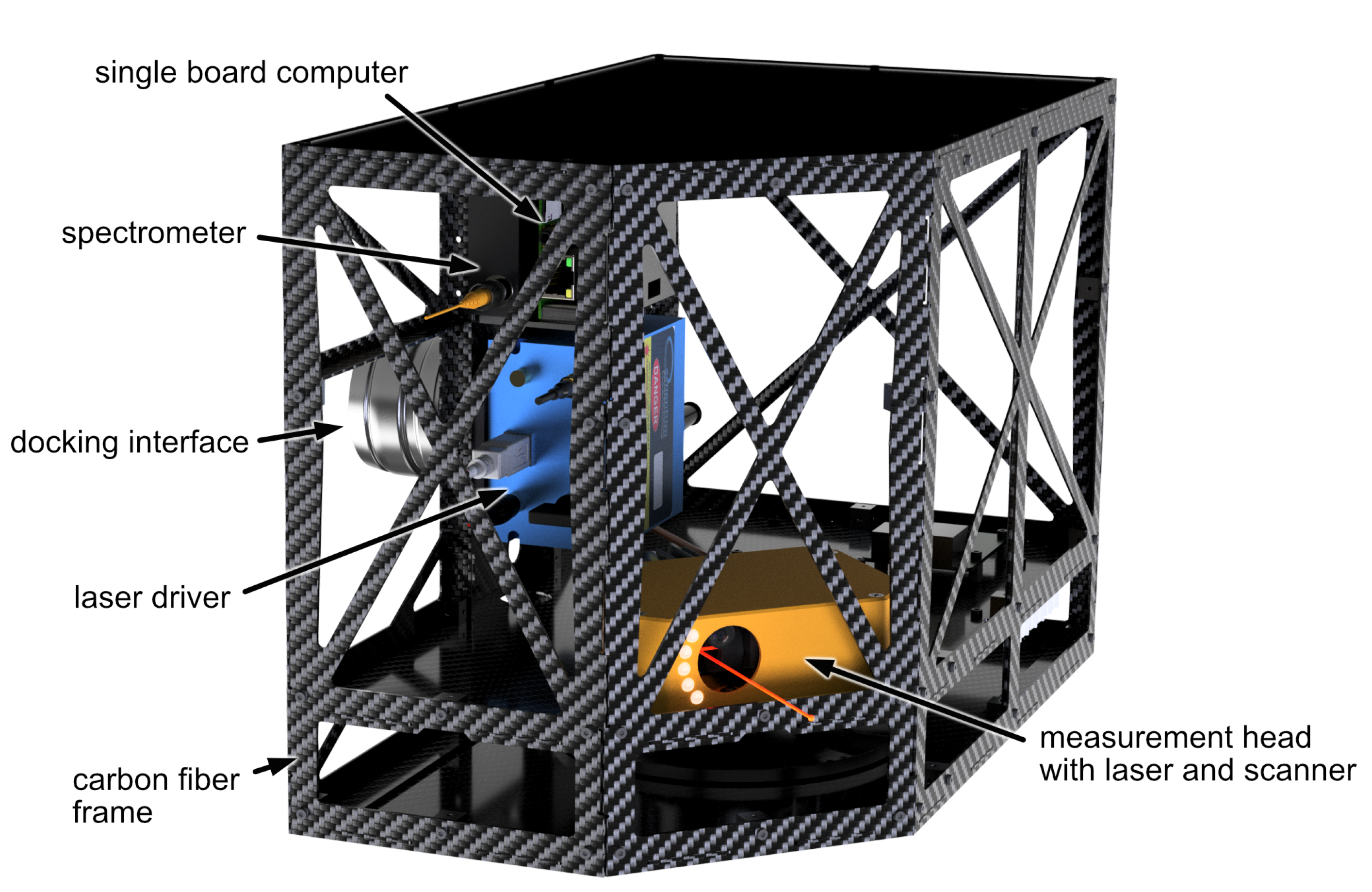
2. ARCHES LIBS Module

The ARCHES LIBS module represents the initial version of the LIBS instrument specifically designed for use with the LRU2 robotic arm. The primary constraints during the instrument’s design were associated with ensuring compatibility with the existing hardware and software developed for the LRU2.

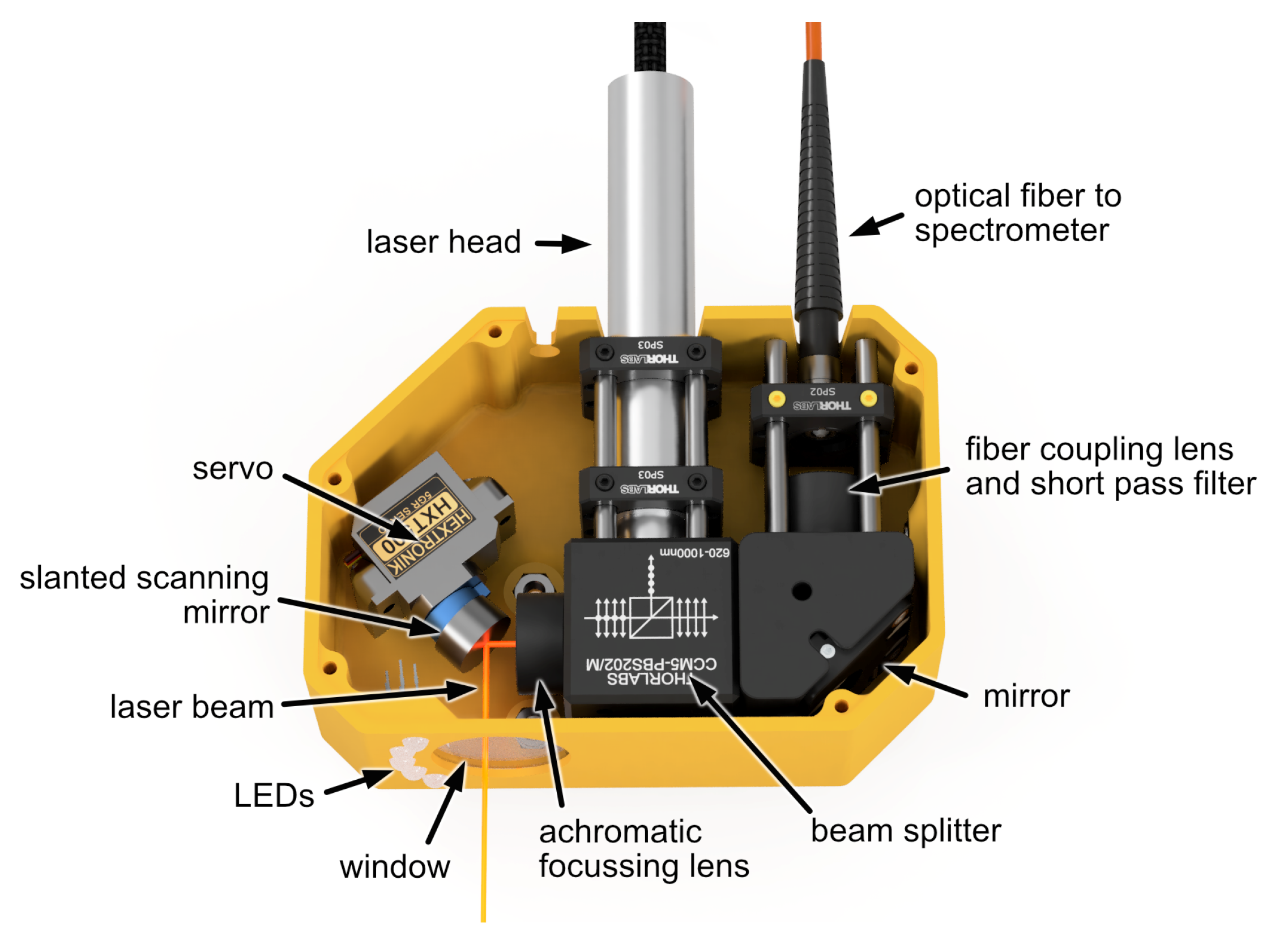
2.1. Hardware Description

The design specifications for the LIBS instrument mandated its compatibility with the standardized payload box system, featuring a cuboid envelope measuring 340 mm × 200 mm × 237 mm. This requirement ensured that the instrument could be stored in the payload fixture of both the lander and LRU2. Additionally, the instrument had to adhere to a mass limit of a maximum of 2.5 kg, facilitating manipulation by the LRU2 robotic arm. The frame of the payload box, constructed from lightweight carbon fiber sheet material, weighs approximately 0.6 kg, allowing for about 1.7 kg of the payload mass to be allocated to the LIBS instrument hardware. The payload box incorporates standardized mechanical and electrical interfaces for efficient data and power transfer between the rover and the instrument. In the case of the LIBS module, a slight modification to the cuboid payload box frame was made by trimming one edge. This adjustment allowed for the addition of a mechanical spacer while maintaining compatibility with the constraints for manipulation and transportation, as illustrated in Figure 1. The mechanical spacer serves to ensure that the LIBS instrument’s optics are focused onto the target when the instrument is in contact with the sample’s surface, eliminating the need for an optical focusing system. The initial design of the spacer involved a 3D-printed straight and slightly flexible bar with a length of 7 cm. This design facilitated a gentle placement of the module on the rock by absorbing some of the forces when contact was made. In a second design iteration, the original spacer was replaced by a cylindrical baffle of the same length as depicted in Figure 2. The baffle features a wavy cut at its outfacing end, enhancing stability during the positioning and placement of the module on the target. This modification serves to reduce loads on the rover’s arm. Additionally, the baffle serves the purpose of enclosing the laser beam, contributing to the laser safety measures implemented in the design.
For material ablation and the generation of the micro-plasma, the compact diode-pumped solid-state (DPSS) MicroJewel laser from Quantum Composers is employed. This passively Q-switched Nd:YAG multi-mode laser delivers pulses of approximately 8 mJ at a wavelength of 1064 nm with pulse durations of about 5 ns. While its nominal maximum power consumption is 20 W, during laser shots, we observed an actual peak current of 1.5 A and a peak power consumption of 72 W. The laser comprises two electrically connected sub-units: the laser driver, a small box measuring 76 × 75 × 50 mm3, and the laser head embedded in a cylindrical aluminum housing with dimensions of 16 mm in diameter and 91 mm in length. To save mass and space, the laser head is mounted without a dedicated passive cooling system, which is typically required for continuous operation. Laboratory tests demonstrated that the laser system could operate without additional cooling when measurements comprised laser bursts with approximately twenty shots along a raster of about ten points.
Figure 3 displays the ARCHES LIBS measurement head encompassing all optical components of the LIBS system. The laser beam is emitted from the laser head, deflected by a beam splitter, and focused with an achromatic lens. After a final reflection from a wobble mirror, the laser exits the measurement head through a glass window and strikes the target at approximately a 7 cm working distance. All optical components are off-the-shelf parts from ThorLabs with a 1/2 inch aperture and anti-reflection coatings. The beam splitter is of the polarizing type, providing around 95% overall reflectivity for the linearly polarized laser beam and between about 45% and 48% transmittance for the collected plasma emission. The achromatic lens is a doublet designed for the visible wavelength region with a focal length of 100 mm. The wobble mechanism is realized by a slanted mount of a flat mirror directly on the shaft of a servo motor, with a slanting angle of 8 degrees between the surface normal of the mirror and the rotation axis. This results in a cost-effective and compact scanning unit that allows sampling along a 3 cm long arc on the target. The reflective coating of the mirror is enhanced silver, providing a good reflectivity of about 96% over the relevant wavelength region of 500 nm to 1064 nm. Furthermore, the mirror is able to withstand the laser beam’s peak energy density, which we estimate to be on the order of 1 J/cm2, resulting from the laser beam’s second-moment width of about 1.7 mm. The laser spot on the sample has a roughly elliptical shape with a Full Width at Half Maximum ( F W H M ) of about 90 μ m along the major axis and about 40 μ m along the minor axis as seen in Figure 4. It should be noted that the F W H M is generally not an ideal measurement unit for multi-mode lasers. However, we chose to use this unit since it is more robust against noise and a reasonable estimate for the size of the laser beam on the target for the purpose of LIBS.
The laser-induced plasma’s emission is directed back into the instrument using the same mirror and achromatic lens. After passing through the beam splitter, it is coupled into an optical fiber connected to the spectrometer. The fiber coupling lens is an achromatic doublet with a focal length of 19 mm, ensuring full utilization of the numerical aperture of 0.22 of the optical fiber. To protect the spectrometer from intense directly back-scattered laser light, a short-pass filter with a cut-off wavelength of 950 nm is added in front of the fiber coupling lens. This filter has a specified optical density of about 5 at the laser wavelength, providing more than 97% transmission in the 500–940 nm pass band. All optical components are securely mounted in a 16 mm ThorLabs steel cage system, which imparts stiffness and long-term stability for the alignment of the optics. The housing of the measurement head is 3D printed from PETG using Fused Deposition Modeling (FDM) technology, providing a lightweight and cost-effective mechanical protection.
The imaging ratio between the field of view and the 100 µm multimode optical fiber is approximately five, determined by the focal length ratio of the focusing lens and the fiber coupling lens. With a field of view diameter of about 500 µm, the most intense core region of the plasma is captured. The compact Avantes AvaSpec-Mini was selected as the spectrometer due to its low mass, volume, and power consumption—approximately 175 g, 95 × 68 × 20 mm3, and 1 W, respectively. This OEM spectrometer employs a symmetrical Czerny–Turner design and an uncooled CMOS linear array with 4096 pixels. It is available in various grating and slit configurations for different wavelength regions from near UV to near IR. The AvaSpec-Mini spectrometer integrated into the ARCHES LIBS instrument is equipped with a 1200 lp/mm grating and a 50 µm slit. It covers a spectral range of 531–776 nm with a spectral resolution of about 0.6 nm. In this wavelength range, the emission lines of several relevant major and minor rock-forming elements (silicon, calcium, sodium, potassium, lithium, and hydrogen) can be detected. If a different wavelength range is more suitable for the elements of interest, the spectrometer can be easily exchanged with another AvaSpec-Mini, as long as it remains compatible with the used optical parts and their coatings. Since the used AvaSpec-Mini was originally purchased for Raman spectroscopy, a 50 µm slit was chosen for higher optical throughput. Typically, better resolution is desired for LIBS, and in future upgrades, a smaller slit can enhance the quality of the LIBS data.
It is important to note that the optical path for plasma emission is not optimized for maximum light-gathering capacity; for instance, half of the unpolarized plasma emission is rejected at the polarizing beam splitter. Additionally, the 200 µm pixel height of the spectrometer would allow for a larger fiber core diameter to collect more light from a broader region of the plasma. However, to prevent detector saturation of the spectrometer at strong emission lines observed during development, a smaller 100 µm fiber was chosen. For the same reason, a polarizing beam splitter was chosen over a dichroic beam splitter, even though the latter can achieve higher transmission for plasma emission. The presented configuration aims for effective utilization of the spectrometer’s dynamic range while leaving enough headroom for materials with strong emission lines.
With the chosen optics configuration, the amount of collected plasma emission and the sensitivity of the spectrometer allow for a high signal-to-noise ratio (SNR) in the LIBS data obtained from a single laser-induced plasma. This, in turn, enables short spectrometer exposure times around the laser pulse, virtually eliminating unwanted background signals from ambient light. An exposure time of 100 µs is used to account for the drift and jitter of the laser pulse timing. The laser manufacturer states a jitter of 1 µs. As the laser is passively Q-switched, control is limited to the start of its pump pulse. The actual release time of the laser pulse drifts with the pump diode temperature, which is uncontrolled in our setup. The generous 100 µs time window, with a 60 µs delay after the pump pulse trigger, allows for capturing the plasma emission under all operating conditions while being short enough to minimize the detector dark current and the influence of ambient light.
All hardware components are under the control of a LattePanda single-board computer (SBC). The SBC also interfaces with a temperature and humidity sensor (DHT11), providing information about the environment inside the payload box during rover operations. Electrical power is supplied through the docking interface between the rover’s robotic arm and the payload box. A power distribution unit (PDU), integrated into the standardized payload box system, distributes electrical power to all instrument components (refer to Figure 1). The payload box infrastructure facilitates communication between the instrument and the rover. Alongside the PDU, this combination forms the Management Unit of the payload box system as illustrated in Figure 5.
All LIBS instrument components collectively weigh approximately 1 kg, well below the total weight limit imposed by the LRU2 robotic arm. To minimize the added torque to the robotic arm’s movement, all instrument components were strategically positioned close to the docking interface at the backside of the payload box.

2.2. Instrument Control and Software Description

The ARCHES LIBS software module comprises the instrument’s firmware running on a LattePanda mini PC with Windows 10 in the payload box, and an analysis software running on a ground station computer—the computer where the operations team receives the data measured in the field. The SBC is equipped with an Arduino Leonardo microcontroller that facilitates direct and fast control of many of the instrument’s hardware components, such as the scanner, which is directly driven by a pulse width modulated (PWM) general purpose input/output (GPIO) pin. It also triggers measurements by providing synchronized trigger signals for releasing the laser pulse and recording a spectrum with the spectrometer. The instrument’s laser and spectrometer are configured by the control software, implemented in LabView on the SBC Windows system. The software also provides the rover with an API, enabling interaction with the instrument through serial communication. An API software library, implemented in Python, runs on the rover in version 1.2 and manages the sending of instructions to the instrument and retrieving data from it.
LIBS measurements are initiated by a single command from the rover, encompassing all adjustable measurement parameters. A measurement can comprise multiple LIBS spectra captured at a single position or different positions on the target along an arc. The number of raster points along the arc and the number of laser shots per position can be specified. Additionally, dark spectra are acquired during a measurement—these are spectrometer data collected without the laser firing, while all measurement parameters remain identical to the LIBS measurement. Measurement data can be retrieved from the instrument as raw or processed data. Data processing includes averaging, removing the dark spectrum from the LIBS spectrum, and generating a preview image of a spectrum. The processed data provide a straightforward way to obtain an initial view of the spectrum and is delivered as a processed graph in PNG format.
If further data analysis is necessary, the data can be retrieved as a binary file containing all information recorded by the instrument. This encompasses spectral information, as well as the temperature and humidity inside the payload box, the temperature of the laser head, the time of the measurement, the number of measurement positions, the corresponding motor positions, and the number of measurements per position. The LIBS spectra are recorded in 4093 channels as 16-bit integers, resulting in a data volume of about 8 kB per spectrum. For a typical measurement involving 5 positions with 20 laser shots and 1 dark spectrum at each position, a file of 840 kB is generated. Wavelength information is retrieved separately, as it remains constant between subsequent measurements, requiring transmission only once. The calibrated wavelength file consists of 4093 channels documented as 32-bit floats, leading to a data volume of 16 kB for wavelength retrieval. All acquired spectra are stored on the internal solid-state drive of the SBC as a backup in the binary raw data format.
Following the successful execution of the measurement procedure, the data can be requested by the rover through the serial communication link. Once the LIBS data are received from the instrument, the rover can transmit it to a ground station computer for scientific analysis.

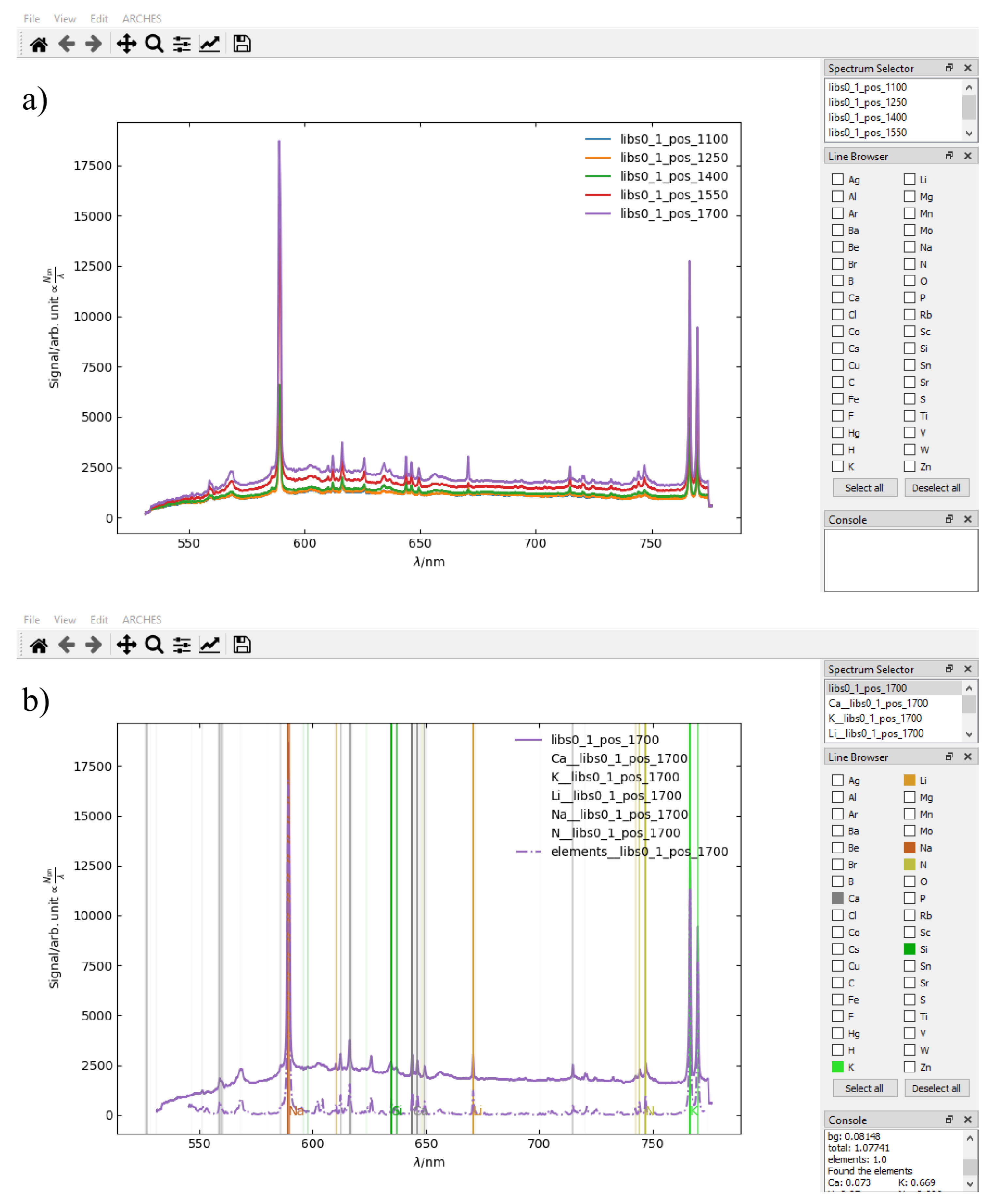
3. Data Visualization and Analysis Tool

To facilitate an immediate assessment of the raw LIBS data, we developed a graphical application that equips scientists with a range of tools for data visualization, manipulation, and analysis. A key feature of the application is an automatic emission line identification algorithm based on the concept of spectral unmixing [32]. The program was implemented in Python 3 utilizing the PyQt5 [33], matplotlib [34], NumPy [35], and SciPy [36] libraries.

3.1. Overview

Upon loading a spectrum, the user can opt to display the LIBS spectra recorded by the instrument in three different ways:
  • Average over all measurement points and shots: This provides a spectrum that is more representative of the bulk composition.
  • Shot averages per position: Emphasizes differences between sampling locations.
  • Individual display of each shot’s spectrum: Reveals possible shot-to-shot variations, allowing for the derivation of chemical trends with depth.
Figure 6a illustrates the application’s main window after opening a measurement, displaying the averages from five different sampling positions.
Once a set of LIBS spectra is loaded, they can be selected and manipulated individually or collectively from the Spectrum Selector on the top right, where each loaded spectrum is listed with its measurement ID. All spectra are initially displayed exactly as recorded by the spectrometer. To account for the ambient lighting conditions and the instrument’s response function, dark spectra can be subtracted and a calibration curve can be applied. For the removal of the background emission, which is usually undiagnostic, the user can choose between a moving minima algorithm [37] and a polynomial fit. In both cases, the fitted background signal is displayed, and parameters can be fine-tuned so that the fit quality can be assessed visually. Finally, the LIBS spectra can be normalized using the sum, maximum, and mean of the spectrum intensity.
Underneath the Spectrum Selector pane, the Line Browser allows the user to display the positions of various rock-forming and trace element’s emission lines as color-coded lines in the spectrum. The intensity of each emission line is represented by the opaqueness of the element marker line. This feature is enabled by the NIST LIBS database [38] and helps in the identification of elements in the spectrum.

3.2. Automatic Line Identification

The emission lines of a recorded spectrum can also be identified automatically by a method that was developed in house [32]. The method is a type of spectral unmixing that involves solving a system of linear equations between an intensity calibrated measured LIBS spectrum and a superposition of reference spectra. In our approach, the reference spectra consist of computationally simulated atomic emissions from typical rock-forming and trace elements and combinations of plasma temperatures, electron densities, and atomic densities. The simulations are obtained from a homogeneous and stationary one-dimensional plasma model under the assumption of local thermal equilibrium [39]. For the simulated emission spectra, temperatures ranging from 5000 K to 30,000 K in eleven equidistant steps are used. We consider electron densities between 1 × 10 22   m 3 and 2 × 10 24   m 3 with six equidistant steps on a logarithmic scale and atomic densities between 1 × 10 20   m 3 and 1 × 10 24   m 3 in five equidistant steps on a logarithmic scale. This range allows us to approximate time-integrated input spectra by using a superposition of simulated reference spectra with different plasma properties. By solving the system of equations, we obtain coefficients for each reference spectrum that was used to match the input spectrum. To obtain a score for each element, the coefficients for the normalized reference spectra corresponding to a given element are summed. The computed score is thereby a measure of how much of the input spectrum signal can be attributed to a given element. It should be noted that this score does not reflect a quantitative measurement of the sample’s constituents.
When applying the automatic line identification tool in the analysis application, an element threshold score can be set inside the corresponding dialog and all elements that fall above that threshold are selected automatically in the Line Browser. Furthermore, the synthesized spectra for each element can be displayed, as well as the fitted sum spectrum. The result of running the automatic spectrum analysis is shown in Figure 6b.

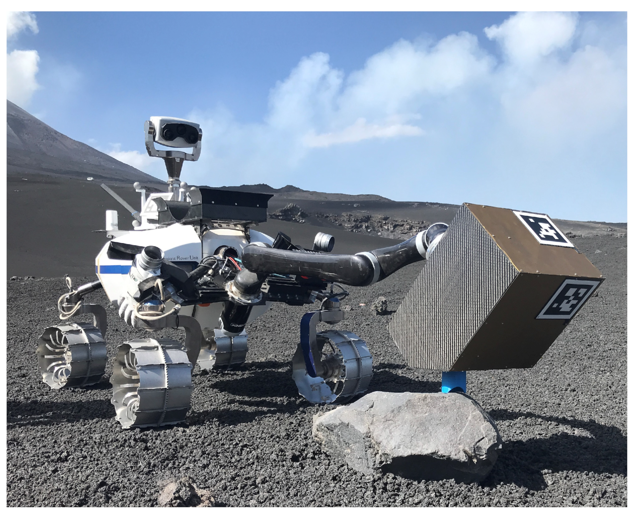
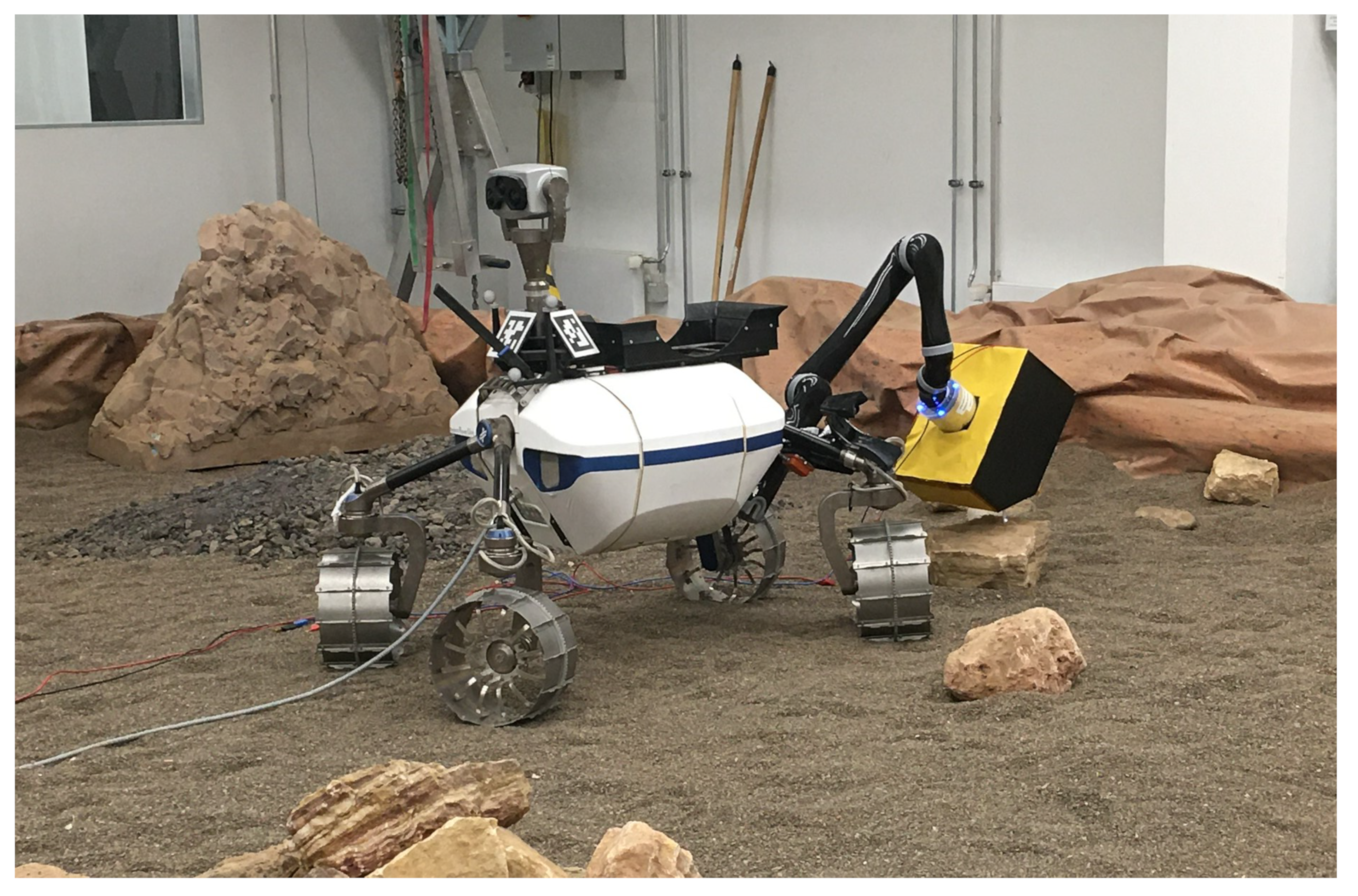
4. ARCHES LIBS Module as LRU2 Payload

We integrated the LIBS module as a modular payload of the lightweight rover unit (LRU) for increased flexibility of the measuring possibilities. The manipulator of the rover can dock to the payload and position the instrument on samples in the reachable workspace: on rock-bed, walls and even on the ceilings of caves. For laser-safety reasons, however, in the ARCHES mission scenario, the LIBS module was only positioned in a way that the laser was targeting downwards.
The entire process of instrument deployment is fully autonomous [40]. The LRU is equipped with two stereo systems that capture depth information around the system. The images are segmented into individual objects using a neural network [41] and transmitted to mission control for further analysis. Mission control selects a rock in the image, and the algorithms on the rover calculate various instrument positions on the sample with two constraints: (1) the contacted rock surface is flat, and (2) it can support the instrument during the measuring process. The manipulator docks to the LIBS instrument on the rover’s carrier, and the planning algorithms compute and execute a collision-free motion to the target position. A Cartesian impedance controller monitors the final contact motion with the sample to ensure adequate forces during deployment. Once in position, the rover queries the control software of the instrument to trigger the measurement as described in Section 2. For immediate feedback on the measurement quality, the instrument software computes a signal-to-noise ratio of the measurement. After the measurement, the manipulator retracts the instrument and stores it in the rover payload carrier. The recorded data are downloaded from the instrument to the rover and uploaded to mission control. Due to the supported autonomy, the system is capable of recording LIBS data for approximately five to seven different samples per hour.
The execution of the LIBS measurement task followed the modular approach presented in [30]. With several hardware and software modular components integrated into both the LRU and the payload module, this strategy provided versatility and robustness to the ARCHES scientific mission. The use of the LIBS module represents a strong application of the guiding paradigm of the LRUs, i.e., a universal, lightweight rover specialized in navigation, exploration, and manipulation of payloads and tools. This paradigm contradicts today’s approach to rover-based planetary exploration, which involves large and heavy mobile systems equipped with permanently installed sub-components to cover their complete mission extent. The increasing number of components, however, escalates the system’s complexity, launch cost, energy consumption, and the risk of failures. A key element that enables the LRU to fulfill a multi-role capability during its missions by handling payloads and tools is the so-called ENVICON docking interface, initially developed during the ROBEX project [42]. The docking interface is used together with a Kinova Jaco Manipulator Arm capable of manipulating 2.5 kg. Its diameter is 102 mm, and it is designed around the manipulator arm’s tool center point (TCP) in such a way that the distance between the payload’s center of gravity and the front face of the TCP is kept as short as possible.
As depicted in Figure 7, the docking interface makes use of a set of flexible sheet metal springs that perform a transition from a more position-tolerant pre-docking regime to a precise and stable fixation. Therefore, the springs open up in front of the barrel-shaped docking interface facing towards their coupling partner. At the beginning of the docking cycle, they form a funnel-like structure that promotes a safe coupling approach (see Figure 7). Within the axial center of both coupling partners, a coaxial connector (male and female counterpart) is situated, enabling the host system to provide power and communication to the payload. This feature, designed together with the initial version of the docking interface, was successfully tested for the first time during the ARCHES project and enabled the efficient usage of the LIBS instrument.
The LIBS module is equipped with the Payload Box Infrastructure Management System (PBIMS), an electronic board responsible for power management and data communication with the host system. The PBIMS provides regulated power to the payload system with up to seven different voltage buses. In the case of the LIBS instrument, only buses with 5 V and 48 V are used. On its power input, the PBIMS can automatically select from up to three different non-regulated power sources ranging between 24 V and 30 V. Telemetry data transmission to the host system is enabled by various wired and wireless communication interfaces on the board. Additionally, onboard sensors such as an inertial measurement unit (IMU) and environmental gauges are included. Once communication is established with the PBIMS onboard controller, telemetry data and power switching control become available. Moreover, the controller runs automated powering schemes for the proper operation of the LIBS instrument, especially during power-up.

5. Results

The ARCHES LIBS module was constructed and tested at the instrument level at the DLR Institute of Optical Sensor Systems (OS) in Berlin. In contrast, the LRU2 is typically located at the DLR Institute of Robotics and Mechatronics (RM) in Oberpfaffenhofen in Southern Germany. The coupling and initial testing of the LIBS module with the LRU2 took place at the Planetary Exploration Laboratory (PEL), an indoor testing facility at DLR Oberpfaffenhofen. This testing aimed to serve as a dress rehearsal for the space demonstration mission field test on Mount Etna and to identify any potentially missing but essential development steps. The test at PEL is detailed in the first part of this section, while the field space demonstration mission is covered in the second part.

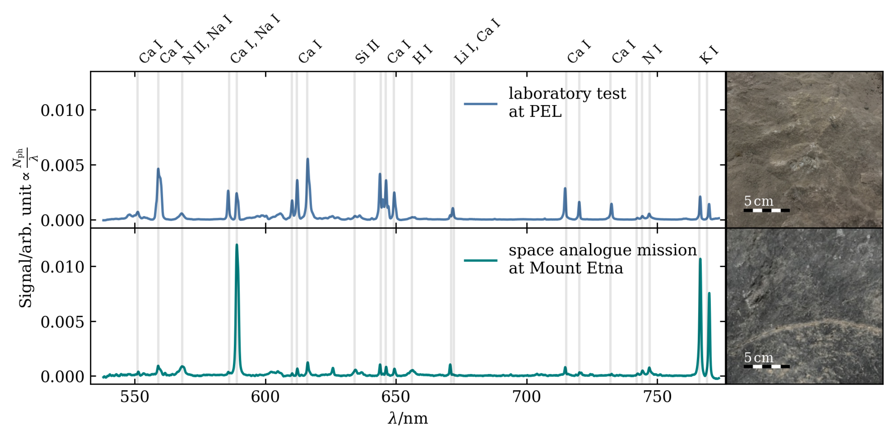
5.1. Laboratory Tests at PEL

The first test for the LIBS instrument alongside the LRU rover took place in October 2021. At that time, the instrument box still featured a pin-shaped 3D-printed distance pin. Additionally, the instrument case was covered with a thin yellow fabric that could be quickly removed to facilitate visual checks and hardware adjustments. In the experiments, the LIBS instrument was docked in a standard payload application. Initially, the instrument was placed on the payload carrier of the LRU, and the robotic arm was in its parking position. The LIBS was then manipulated onto a sample rock of convenient height using the manipulator arm. This rock served as a test target, and the arm positioned the instrument so that the distance pin touched the target from above, and the laser aperture faced down on the target. Subsequently, a firing sequence of the laser was automatically initiated. As depicted in Figure 8, the box was still tethered by a power cable, bypassing the power connector of the docking interface. This was necessary, as the power required for firing the laser had to be conveniently buffered by the LIBS instrument’s PBIMS. Since the two development tracks were carried out at different locations (DLR-OS in Berlin and DLR-RM in Oberpfaffenhofen), the adjustment of the integrated buffer had to be performed based on measurement data derived from the tests. Throughout the tests, firing sequences were successfully executed, and all data needed for the remaining optimizations to ensure the safe and reliable operation of the instrument were collected. The distance pin was found to be too weak for consecutive measurements and was subsequently redesigned as a cylindrical baffle for the dress rehearsal. Following this dress rehearsal experiment, the LIBS module was returned to DLR-OS in Berlin.

5.2. Space Analogue Mission at Mount Etna, Sicily

The volcanic foothills of Mount Etna in Sicily, Italy, were chosen as a suitable location for the ARCHES space analogue demonstration mission due to their resemblance to barren extraterrestrial surfaces like the Moon. The mission involved a diverse team of interconnected mobile and static robots, comprising rovers, a drone, and a lander. The team operated collaboratively and semi-autonomously to deploy tools and sensors in the field [19,27,28]. Additionally, the ARCHES team collaborated with the ESA METERON project (Multipurpose End-To-End Robotics Operations Network), focusing on preparing for future human–robotic exploration scenarios [29].
Originally scheduled for summer 2020, the ARCHES space analogue demonstration mission faced two postponements due to the COVID-19 pandemic and was ultimately conducted in summer 2022. The entire campaign spanned four weeks, encompassing on-site preparations of hardware, software, and networks, the execution of the demonstration mission, and subsequent dismantling and packing activities.
The integrated mission scenario involved a combination of operator instructions and autonomous robot decisions. The mission was organized into two parts for geological exploration (Geo I and Geo II) and a third part, where a low-frequency antenna array was installed in the field as detailed in [19,27,28].
Geo I primarily focused on the technical demonstration of cooperating autonomous robotic assets. For this purpose, the two LRUs of DLR were deployed alongside the flying drone ARDEA to autonomously explore the site, provide data for an accurate local map, and perform in-situ analysis. In addition to exploration and scientific measurements, Geo I also demonstrated the end-to-end scientific process of sample selection. In Geo II, the focus was on sample return comprising two additional rovers and featuring teleoperations by an astronaut. The LIBS instrument and its robotic platform, the LRU2, were part of Geo I, and we will focus here on its implementation and performance in this part of the mission scenario.
In the overall mission scenario, the Lander arrived at a location that was chosen by scientists and mission operators beforehand, based on orbital data. In Geo I, as a first action, LRU1 and the ARDEA drone are sent for mapping and, hence, to give a visual overview of the landing site in the proximity (max. 50 m distance) of the Lander. For this purpose, the LRU1 is equipped with seven cameras in its pan–tilt unit including a scientific camera, navigation cameras, and wide-angle stereo cameras, see [19] for more details. While LRU1 could successfully perform its task, the ARDEA drone could unfortunately not fly for the demonstration due to too strong winds [28]. The first task of LRU2 in Geo 1 was the collection of a sample box from the Lander and collecting rock and soil samples in the field with a robotic hand coupled to its robotic arm and it completed this task successfully. The second task of LRU2 was then to use the LIBS module to carry out a geochemical analysis of three different rocks at different locations in the area explored by the ARCHES robot team. LRU2 successfully collected the LIBS payload box from the Lander, placed it into the cage on its back and drove to the first target of interest. When an appropriate distance to the target was reached, stereo images were acquired with the rover cameras, and the operating team selected a target from a segmented image (see details described in Section 4 and [40]). The LIBS module was then coupled to the robotic arm and positioned onto the rock, see Figure 2 and Figure 9. Here, the rover commanded the LIBS instrument to initiate the measurement process, which involved the triggering of a sequence of laser pulses and the recording of the spectra of the laser-induced plasmas. The rover then downloaded the data from the LIBS module and transmitted them to mission control, where they were displayed in the ARCHES LIBS GUI and analyzed by the scientific team. The LIBS measurement by the LRU2 in the field test was then repeated two additional times.

5.3. LIBS Data Analysis

The acquired LIBS data enable both qualitative and quantitative elemental analysis of the investigated sample. In the wavelength range of the ARCHES LIBS instrument from 531 to 776 nm, several major and minor rock-forming elements are available. Figure 10 displays two LIBS spectra acquired with the ARCHES LIBS: one from an unknown rock at the testbed at PEL and the other from a presumably igneous rock with a volcanic context at the foothills of Mt. Etna during the demonstration mission. Each spectrum represents the average of ten laser shots from a single position on the sampled rock.
The spectrum acquired indoors at PEL exhibits strong calcium (Ca) emission, moderate emission of sodium (Na) and potassium (K), and silicon (Si) emission. The spectrum obtained at Mt. Etna shows strong emission of the alkali metals Na, K, and lithium (Li), and low emission of Ca and Si. Hydrogen (H) is present in both spectra, along with the nitrogen (N) triplet, resulting from the breakdown of ambient gas contributing to the laser-induced plasma. Both spectra feature emission lines of observable elements with sufficient signal-to-noise ratio (SNR), allowing further analysis, such as classification or the derivation of quantitative elemental values. For the latter, reference LIBS data were obtained with the ARCHES LIBS module from a set of geological samples provided by ESA, and the results will be presented in an upcoming publication.

6. Discussion

None of the anticipated problems during the demonstration mission turned out to be showstoppers. For instance, we opted to use the laser without the dedicated plate for passive cooling and did not implement any active temperature control or ventilator. The laser provider specifies an operational temperature range from 15 to 30 °C, which raised concerns about potential conflicts with local temperatures at the test site, where mornings can be rather chilly and afternoons very hot. However, we did not encounter any issues related to the laser being too cold or becoming too hot. In the ARCHES mission scenarios, the time needed to move between different measurement locations was sufficient for the laser to deliver several hundred laser pulses without additional cooling.
The housing and envelope of the LIBS module were chosen as constraints from the rover and were kept to facilitate the handling of the module by the rover. However, during the field test on Mt. Etna, this design revealed drawbacks when strong winds imposed additional loads on the rover’s arm, making it challenging to handle. Since the hardware of the LIBS instrument only occupies a fraction of the current modular box, future designs can be more compact, lightweight, and less susceptible to winds.
Furthermore, since the visual context of the measured target is essential for the scientific analysis and interpretation of the spectral data, a camera is typically an important part of a LIBS payload. Unfortunately, the integrated camera in this first version of the ARCHES LIBS module was faulty and could not be used in the demonstration mission. A functional camera will be integrated in the next upgrade of the LIBS modular payload box.
The spectrometer we utilized in this initial version of the LIBS module was originally configured for Raman spectroscopy with a 50 µm slit to achieve higher throughput. An upgrade could involve using a spectrometer with a smaller slit to improve the spectral resolution for LIBS, which would also allow for the use of a larger 200 µm fiber. Nevertheless, the selected spectrometer and its spectral range proved sufficient for demonstrating the functionality of the LIBS module for the DLR LRU2, enabling the collection of meaningful LIBS data from the field. However, to maximize the scientific value, an extended wavelength range that covers additional major elements such as magnesium, iron, and titanium, as well as more minor and trace elements, would be beneficial. In an upgraded version, we will explore options to increase the spectral range, either at the cost of resolution or by adding an additional spectrometer.

7. Summary and Conclusions

The LIBS instrument module developed for the DLR LRU2 rover demonstrated successful performance during the field test at Mt. Etna, Sicily, obtaining suitable in-situ LIBS data of the geological targets. The ARCHES LIBS module, a first prototype, underwent minimal alterations after the indoor test at DLR-RM, including replacing a spacer with a baffle and changing the cover. To the best of our knowledge, it represents the first arm-deployed LIBS instrument on a rover.
As part of a sustainability-focused project, the ARCHES LIBS module is currently undergoing upgrades and adaptations for soil analysis in an agricultural context. The enhancements include the implementation of a camera for context images, a more compact design, and the integration of additional sensors, such as a microphone, to improve data analysis. Furthermore, in an upgraded version, efforts will be made to extend the wavelength range, covering additional elements of interest.

Author Contributions

Conceptualization, S.S., S.F., E.D., A.W., A.B. and H.-W.H.; methodology, S.S., F.S., E.D., S.F., P.L., A.F.P. and B.V.; software, F.S. and S.F.; validation, S.S., F.S., E.D., S.F. and P.L.; formal analysis, S.S. and F.S.; investigation, S.S., F.S., P.L., A.F.P., R.S. and B.V.; resources, A.W., A.B. and H.-W.H.; data curation, S.S. and F.S.; writing—original draft preparation, S.S., F.S., E.D., S.F., P.B.H., P.L., A.F.P., R.S. and B.V.; writing—review and editing, S.S., F.S., S.F., R.S., A.W., A.B. and H.-W.H.; visualization, S.S., F.S., E.D., S.F., P.L. and A.F.P.; supervision, S.S.; project administration, S.S. and A.W.; funding acquisition, A.W., A.B. and H.-W.H. All authors have read and agreed to the published version of the manuscript.

Funding

This research was funded by the Helmholtz Association in the strategic future topic ARCHES ZT-0033.

Institutional Review Board Statement

Not applicable.

Informed Consent Statement

Not applicable.

Data Availability Statement

Data can be made available upon request. All data obtained during the ARCHES space demo mission will be made available to the public.

Acknowledgments

We gratefully acknowledge support from DLR and colleagues for the preparation and successful implementation of the space demonstration mission at Mt. Etna, Sicily.

Conflicts of Interest

The authors declare no conflicts of interest.

Abbreviations

The following abbreviations are used in this manuscript:
APIApplication Programming Interface
ARCHESAutonomous Robotic Networks to Help Modern Societies
DLRDeutsches Zentrum für Luft- und Raumfahrt (German Aerospace Center)
DPSSDiode Pumped Solid State
FDMFused Deposition Modeling
GPIOGeneral Purpose Input/Output
GUIGraphical User Interface
IMUInertial Measurement Unit
LEDLight Emitting Diode
LIBSLaser-Induced Breakdown Spectroscopy
LRULightweight Rover Unit
NIRNear Infrared
PBIMSPayload Box Infrastructure Management System
PCBPrinted Circuit Board
PDUPower Distribution Unit
PELPlanetary Exploration Laboratory
PETGPolyethylenenterephthalat-Glycol
PNGPortable Network Graphics
PWMPulse Width Modulated
ROBEXRobotic Exploration of Extreme Environments
SBCSingle Board Computer
SNRSignal-to-Noise Ratio
SSDSolid-State Drive
UVUltraviolet

References

  1. Cremers, D.A.; Radziemski, L.J. Handbook of Laser-Induced Breakdown Spectroscopy; John Wiley & Sons: Hoboken, NJ, USA, 2013. [Google Scholar]
  2. Maurice, S.; Wiens, R.C.; Saccoccio, M.; Barraclough, B.; Gasnault, O.; Forni, O.; Mangold, N.; Baratoux, D.; Bender, S.; Berger, G.; et al. The ChemCam Instrument Suite on the Mars Science Laboratory (MSL) Rover: Science Objectives and Mast Unit Description. Space Sci. Rev. 2012, 170, 95–166. [Google Scholar] [CrossRef]
  3. Wiens, R.C.; Maurice, S.; Barraclough, B.; Saccoccio, M.; Barkley, W.C.; Bell, J.F.; Bender, S.; Bernardin, J.; Blaney, D.; Blank, J.; et al. The ChemCam Instrument Suite on the Mars Science Laboratory (MSL) Rover: Body Unit and Combined System Tests. Space Sci. Rev. 2012, 170, 167–227. [Google Scholar] [CrossRef]
  4. Maurice, S.; Clegg, S.M.; Wiens, R.C.; Gasnault, O.; Rapin, W.; Forni, O.; Cousin, A.; Sautter, V.; Mangold, N.; Le Deit, L.; et al. ChemCam activities and discoveries during the nominal mission of the Mars Science Laboratory in Gale crater, Mars. J. Anal. At. Spectrom. 2016, 31, 863–889. [Google Scholar] [CrossRef]
  5. Wiens, R.C.; Maurice, S.; Robinson, S.H.; Nelson, A.E.; Cais, P.; Bernardi, P.; Newell, R.T.; Clegg, S.; Sharma, S.K.; Storms, S.; et al. The SuperCam Instrument Suite on the NASA Mars 2020 Rover: Body Unit and Combined System Tests. Space Sci. Rev. 2021, 217, 4. [Google Scholar] [CrossRef] [PubMed]
  6. Maurice, S.; Wiens, R.C.; Bernardi, P.; Caïs, P.; Robinson, S.; Nelson, T.; Gasnault, O.; Reess, J.M.; Deleuze, M.; Rull, F.; et al. The SuperCam Instrument Suite on the Mars 2020 Rover: Science Objectives and Mast-Unit Description. Space Sci. Rev. 2021, 217, 47. [Google Scholar] [CrossRef]
  7. Xu, W.; Liu, X.; Yan, Z.; Li, L.; Zhang, Z.; Kuang, Y.; Jiang, H.; Yu, H.; Yang, F.; Liu, C.; et al. The MarSCoDe Instrument Suite on the Mars Rover of China’s Tianwen-1 Mission. Space Sci. Rev. 2021, 217, 64. [Google Scholar] [CrossRef]
  8. Wan, X.; Li, C.; Wang, H.; Xu, W.; Jia, J.; Xin, Y.; Ma, H.; Fang, P.; Ling, Z. Design, function, and implementation of china’s first libs instrument (Marscode) on the zhurong mars rover. At. Spectrosc. 2021, 42, 294–298. [Google Scholar] [CrossRef]
  9. Laxmiprasad, A.; Sridhar Raja, V.; Menon, S.; Goswami, A.; Rao, M.; Lohar, K. An in situ laser induced breakdown spectroscope (LIBS) for Chandrayaan-2 rover: Ablation kinetics and emissivity estimations. Adv. Space Res. 2013, 52, 332–341. [Google Scholar] [CrossRef]
  10. Laxmiprasad, A.; Sridhar Raja, V.; Goswami, A.; Lohar, K.A.; Rao, M.V.H.; Shila, K.V.; Mahajan, M.; Raha, B.; Smaran, T.S.; Krishnamprasad, B. Laser Induced Breakdown Spectroscope on Chandrayaan-2 Rover: A miniaturized mid-UV to visible active spectrometer for lunar surface chemistry studies. Curr. Sci. 2020, 4, 118. [Google Scholar]
  11. Laan, E.C.; Ahlers, B.; Van Westrenen, W.; Heiligers, J.; Wielders, A. Moon4You: A combined Raman/LIBS instrument for lunar exploration. In Proceedings of the Instruments and Methods for Astrobiology and Planetary Missions XII, San Diego, CA, USA, 4–6 August 2009; Volume 7441, pp. 372–379. [Google Scholar]
  12. Courreges-Lacoste, G.B.; Ahlers, B.; Pérez, F.R. Combined Raman spectrometer/laser-induced breakdown spectrometer for the next ESA mission to Mars. Spectrochim. Acta A Mol. Biomol. Spectrosc. 2007, 68, 1023–1028. [Google Scholar] [CrossRef]
  13. Court, A. Raman-LIBS, a Journey from Mars to Earth Via the Moon. In Proceedings of the IEEE Aerospace Conference, Big Sky, MT, USA, 2–9 March 2019; pp. 1–6. [Google Scholar] [CrossRef]
  14. Arp, Z.A.; Cremers, D.A.; Harris, R.D.; Oschwald, D.M.; Parker, G.R., Jr.; Wayne, D.M. Feasibility of generating a useful laser-induced breakdown spectroscopy plasma on rocks at high pressure: Preliminary study for a Venus mission. Spectrochim. Acta Part B At. Spectrosc. 2004, 59, 987–999. [Google Scholar] [CrossRef]
  15. Wiens, R.C.; Maurice, S.; Clegg, S.; Sharma, S.; Misra, A.; Bender, S.; Newell, R.; Dallmann, N.; Lanza, N.; Forni, O.; et al. Compact Remote Raman-LIBS Instrument for Mars or Titan. In Proceedings of the 43rd Lunar and Planetary Science Conference, The Woodlands, TX, USA, 19–23 March 2012; Volume 43, p. 1699. [Google Scholar]
  16. Wiens, R.C.; Udry, A.; Beyssac, O.; Quantin-Nataf, C.; Mangold, N.; Cousin, A.; Mandon, L.; Bosak, T.; Forni, O.; McLennan, S.M.; et al. Compositionally and density stratified igneous terrain in Jezero crater, Mars. Sci. Adv. 2022, 8, eabo3399. [Google Scholar] [CrossRef] [PubMed]
  17. Gasnault, O.; Lanza, N.; Wiens, R.; Maurice, S.; Mangold, N.; Johnson, J.; Dehouck, E.; Beck, P.; Cousin, A.; Pinet, P.; et al. Chemcam: Zapping mars for 10 years (and more). In Proceedings of the Lunar and Planetary Science Conference, The Woodlands, TX, USA, 13–17 March 2023; Volume 54, p. 2076. [Google Scholar]
  18. Schuster, M.J.; Brunner, S.G.; Bussmann, K.; Büttner, S.; Dömel, A.; Hellerer, M.; Lehner, H.; Lehner, P.; Porges, O.; Reill, J.; et al. Towards autonomous planetary exploration: The Lightweight Rover Unit (LRU), its success in the SpaceBotCamp challenge, and beyond. J. Intell. Robot. Syst. 2019, 93, 461–494. [Google Scholar] [CrossRef]
  19. Schuster, M.J.; Muller, M.G.; Brunner, S.G.; Lehner, H.; Lehner, P.; Sakagami, R.; Domel, A.; Meyer, L.; Vodermayer, B.; Giubilato, R.; et al. The ARCHES Space-Analogue Demonstration Mission: Towards Heterogeneous Teams of Autonomous Robots for Collaborative Scientific Sampling in Planetary Exploration. IEEE Robot. Autom. Lett. 2020, 5, 5315–5322. [Google Scholar] [CrossRef]
  20. Wedler, A.; Schuster, M.J.; Müller, M.G.; Vodermayer, B.; Meyer, L.; Giubilato, R.; Vayugundla, M.; Smisek, M.; Dömel, A.; Steidle, F.; et al. German Aerospace Center’s advanced robotic technology for future lunar scientific missions: DLR’s Advanced Robotic Technology. Philos. Trans. R. Soc. A Math. Phys. Eng. Sci. 2021, 379, 20190574. [Google Scholar] [CrossRef] [PubMed]
  21. Francis, R.; Estlin, T.; Doran, G.; Johnstone, S.; Gaines, D.; Verma, V.; Burl, M.; Frydenvang, J.; Montaño, S.; Wiens, R.C.; et al. AEGIS autonomous targeting for ChemCam on Mars Science Laboratory: Deployment and results of initial science team use. Sci. Robot. 2017, 2, eaan4582. [Google Scholar] [CrossRef]
  22. Vogt, D.S.; Schröder, S.; Richter, L.; Deiml, M.; Weßels, P.; Neumann, J.; Hübers, H.W. VOILA on the LUVMI-X Rover: Laser-Induced Breakdown Spectroscopy for the Detection of Volatiles at the Lunar South Pole. Sensors 2022, 22, 9518. [Google Scholar] [CrossRef]
  23. Rammelkamp, K.; Schröder, S.; Lomax, B.; Clave, E.; Hübers, H.W. LIBS and Raman spectroscopy for extraterrestrial in-situ resource scouting and extraction processes. Frontiers, 2024; in revision. [Google Scholar]
  24. Rauschenbach, I.; Jessberger, E.; Pavlov, S.; Hübers, H.W. Miniaturized Laser-Induced Breakdown Spectroscopy for the in-situ analysis of the Martian surface: Calibration and quantification. Spectrochim. Acta Part B At. Spectrosc. 2010, 65, 758–768. [Google Scholar] [CrossRef]
  25. Knight, A.K.; Scherbarth, N.L.; Cremers, D.A.; Ferris, M.J. Characterization of laser-induced breakdown spectroscopy (LIBS) for application to space exploration. Appl. Spectrosc. 2000, 54, 331–340. [Google Scholar] [CrossRef]
  26. Effenberger, A.J.; Scott, J.R. Effect of atmospheric conditions on LIBS spectra. Sensors 2010, 10, 4907–4925. [Google Scholar] [CrossRef] [PubMed]
  27. Wedler, A.; Müller, M.G.; Schuster, M.; Durner, M.; Brunner, S.; Lehner, P.; Lehner, H.; Dömel, A.; Vayugundla, M.; Steidle, F.; et al. Preliminary Results for the Multi-Robot, Multi-Partner, Multi-Mission, Planetary Exploration Analogue Campaign on Mount Etna. In Proceedings of the International Astronautical Congress, IAC 2021, Dubai, United Arab Emirates, 25 October 2021. [Google Scholar]
  28. Wedler, A.; Müller, M.G.; Schuster, M.; Durner, M.; Lehner, P.; Dömel, A.; Steidle, F.; Vayugundla, M.; Sakagami, R.; Meyer, L.; et al. Finally! insights into the arches lunar planetary exploration analogue campaign on etna in summer 2022. In Proceedings of the 73rd International Astronautical Congress, IAC 2022, Paris, France, 18–22 September 2022. [Google Scholar]
  29. Carey, W.; Krueger, T.; Wedler, A.; Wormnes, K.; Grenouilleau, J.; Ferreira, E.; Nergaard, K.; van der Hulst, F.; den Exter, E.; Gerdes, L.; et al. METERON Analog-1: A Touch Remote. In Proceedings of the International Astronautical Congress, IAC 2022, Paris, France, 18–22 September 2022. [Google Scholar]
  30. Prince, A.F.; Vodermayer, B.; Pleintinger, B.; Kolb, A.; Franchini, G.; Staudinger, E.; Dietz, E.; Schröder, S.; Frohmann, S.; Seel, F.; et al. Modular Mechatronics Infrastructure for robotic planetary exploration assets in a field operation scenario. Acta Astronaut. 2023, 212, 160–176. [Google Scholar] [CrossRef]
  31. Weiner, P.; Starke, J.; Hundhausen, F.; Beil, J.; Asfour, T. The kit prosthetic hand: Design and control. In Proceedings of the 2018 IEEE/RSJ International Conference on Intelligent Robots and Systems (IROS), Madrid, Spain, 1–5 October 2018; pp. 3328–3334. [Google Scholar]
  32. Hansen, P.B. Modeling of LIBS Spectra Obtained in Martian Atmospheric Conditions; Humboldt Universitaet zu Berlin: Berlin, Germany, 2022. [Google Scholar]
  33. PyQt5. Version 5.15.7. Available online: https://pypi.org/project/PyQt5/ (accessed on 28 January 2024).
  34. Hunter, J.D. Matplotlib: A 2D graphics environment. Comput. Sci. Eng. 2007, 9, 90–95. [Google Scholar] [CrossRef]
  35. Harris, C.R.; Millman, K.J.; van der Walt, S.J.; Gommers, R.; Virtanen, P.; Cournapeau, D.; Wieser, E.; Taylor, J.; Berg, S.; Smith, N.J.; et al. Array programming with NumPy. Nature 2020, 585, 357–362. [Google Scholar] [CrossRef] [PubMed]
  36. Virtanen, P.; Gommers, R.; Oliphant, T.E.; Haberland, M.; Reddy, T.; Cournapeau, D.; Burovski, E.; Peterson, P.; Weckesser, W.; Bright, J.; et al. SciPy 1.0: Fundamental Algorithms for Scientific Computing in Python. Nat. Methods 2020, 17, 261–272. [Google Scholar] [CrossRef] [PubMed]
  37. Yaroshchyk, P.; Eberhardt, J.E. Automatic correction of continuum background in Laser-induced Breakdown Spectroscopy using a model-free algorithm. Spectrochim. Acta Part B At. Spectrosc. 2014, 99, 138–149. [Google Scholar] [CrossRef]
  38. Kramida, A.; Olsen, K.; Ralchenko, Y. Nist Libs Database; National Institute of Standards and Technology, US Department of Commerce: Gaithersburg, MD, USA, 2019.
  39. Cristoforetti, G.; De Giacomo, A.; Dell’Aglio, M.; Legnaioli, S.; Tognoni, E.; Palleschi, V.; Omenetto, N. Local Thermodynamic Equilibrium in Laser-Induced Breakdown Spectroscopy: Beyond the McWhirter criterion. Spectrochim. Acta Part B At. Spectrosc. 2010, 65, 86–95. [Google Scholar] [CrossRef]
  40. Lehner, P.; Sakagami, R.; Boerdijk, W.; Dömel, A.; Durner, M.; Franchini, G.; Prince, A.; Lakatos, K.; Risch, D.L.; Meyer, L.; et al. Mobile Manipulation of a Laser-induced Breakdown Spectrometer for Planetary Exploration. In Proceedings of the 2023 IEEE Aerospace Conference, Big Sky, MT, USA, 4–11 March 2023; pp. 1–19. [Google Scholar] [CrossRef]
  41. Durner, M.; Boerdijk, W.; Fanger, Y.; Sakagami, R.; Risch, D.L.; Triebel, R.; Wedler, A. Autonomous Rock Instance Segmentation for Extra-Terrestrial Robotic Missions. In Proceedings of the 2023 IEEE Aerospace Conference, AERO 2023, Big Sky, MT, USA, 4–11 March 2023. [Google Scholar]
  42. Wedler, A.; Hellerer, M.; Rebele, B.; Gmeiner, H.; Vodermayer, B.; Bellmann, T.; Barthelmes, S.; Rosta, R.; Lange, C.; Witte, L.; et al. Robex—Components and methods for the planetary exploration demonstration mission. In Proceedings of the 13th Symposium on Advanced Space Technologies in Robotics and Automation (ASTRA), Noordwijk, The Netherlands, 10–13 May 2015. [Google Scholar]
Figure 1. CAD model of LIBS payload module. The power distribution unit that comes with the standardized payload box is located in the lower separated partition in the rear in this perspective.
Applsci 14 02467 g001
Figure 2. LRU2 with LIBS module taking a measurement during the space analogue mission at Mt. Etna, Sicily.
Applsci 14 02467 g002
Figure 3. CAD model of LIBS measurement head. The laser exits the measurement head towards the ground. A baffle ensures that the instrument is positioned at the appropriate distance to the target with respect to the focal plane of the laser beam.
Applsci 14 02467 g003
Figure 4. The instrument’s laser beam profile near the plane of the baffle, where samples are located during measurements, is roughly elliptical, with a F W H M along the major axis of approximately 90 μ m and a F W H M along the minor axis of about 40 μ m. Due to geometrical constraints, the measurement was conducted approximately 4.5 mm outside of the exit plane of the baffle.
Applsci 14 02467 g004
Figure 5. Schematic of instrument’s hardware groups and how they are interconnected.
Applsci 14 02467 g005
Figure 6. Screenshots of the application used to visualize and analyze the recorded LIBS data. In panel (a), the shot averages per position of a LIBS measurement are shown just after loading the data. Panel (b) shows the GUI after using the automatic line identification feature. For a better overview, the titanium (Ti) lines are hidden.
Applsci 14 02467 g006
Figure 7. Docking interface ENVICON, showing the retracted grasping springs as well as the male, co-axial connector (left). The JACO robotic manipulator arm on a trajectory to the pre-docking position and the grasping springs opened to form a funnel-like structure (right).
Applsci 14 02467 g007
Figure 8. LRU2 with LIBS module taking a measurement of a rock during testing at the planetary exploration laboratory (PEL) at DLR Oberpfaffenhofen.
Applsci 14 02467 g008
Figure 9. Picture sequence, showing the LRU2 coupling its robotic arm to the LIBS modular payload box on its back and placing the instrument onto a target for the measurement. In the background, LRU1 equipped with cameras can be seen.
Applsci 14 02467 g009
Figure 10. LIBS spectra recorded with the ARCHES LIBS instrument on rocks during tests at PEL and the demonstration mission on Mt. Etna. Each spectrum represents the average of ten laser shots from a single position on the sampled rock. The continuum signal was removed using a moving minima algorithm, and each spectrum is normalized with its respective sum for easier comparison of the spectra’s relative line intensities.
Applsci 14 02467 g010
Disclaimer/Publisher’s Note: The statements, opinions and data contained in all publications are solely those of the individual author(s) and contributor(s) and not of MDPI and/or the editor(s). MDPI and/or the editor(s) disclaim responsibility for any injury to people or property resulting from any ideas, methods, instructions or products referred to in the content.

