Abstract
As the modular industry expands, the most widely used building materials are primarily concrete, steel, and wood. However, the use of wood and steel is severely limited compared to concrete for reasons such as durability and economy. To overcome these shortcomings, we aimed to apply ultra-high-performance fiber-reinforced concrete (UHPFRC), which has excellent compressive strength and tensile strength, high durability, and minimal reinforcement with steel fibers. In this study, research was conducted on the development of unit box-type architectural modules using UHPFRC with a compressive strength of 120 MPa and a tensile strength of greater than 7 MPa. Various amounts of steel fibers (Vf = 1.0, 1.5, and 2.0%) were evaluated to determine the optimal mixing ratio of UHPFRC, in which both the durability and mechanical performance were assessed. The compressive strength and tensile strength of UHPFRC were found to be 132 MPa and 10.1 MPa, respectively, while its resistance to chloride penetration averaged 14.47 coulombs, indicating superior durability compared to conventional concrete. To reduce the weight of the unit components of the architectural modular system, both normal concrete (NC) components and UHPFRC were applied. The main variables in the flexural tests were the cross-sectional thickness, steel fiber content, and presence of an insulation material, comprising a total of three variables for evaluating the flexural performance. The application of UHPFRC with a compressive strength of 120 MPa, a cross-sectional thickness of 120 mm, and a 10 mm diameter reinforcement provided a similar performance to that of NC components while reducing concrete usage by 60% compared to NC components. Additionally, structural analysis was performed to prototype the unit box-type modular structure using UHPFRC. The modular structural system developed in this study was found to reduce construction costs by 18.7% compared to traditional steel structural systems. Further research is necessary to address issues such as floor slab vibration and noise, connections, and expansion to multistory buildings for commercialization of modular structures using UHPFRC.
1. Introduction
The construction industry is projected to experience steady growth until 2026, as it undergoes restructuring following the gradual relaxation of global lockdown measures implemented in response to the COVID-19 pandemic. However, the construction of the majority of buildings currently relies heavily on traditional methods that involve onsite concrete pouring. The drawbacks of these conventional methods include difficulties in sourcing construction materials, increased construction costs, inadequate quality control due to the demand for shortened construction periods, and a shortage of skilled workers [1,2,3,4]. Measures are necessary to address these issues and improve construction management.
The introduction of factory production methods for concrete structures (offsite construction) can offer advantages such as low cost, fast delivery, and high performance [5,6,7,8,9]. Continuous efforts are being made to increase the production efficiency compared to traditional methods. In this regard, modular construction methods minimize onsite construction and simplify process management, utilizing advantages such as reduced construction time and streamlined processes [10,11,12]. Furthermore, factory-controlled production of building components enables comprehensive quality control in terms of concrete mixing, pouring, curing, and precise production due to the accuracy of the mold dimensions [13,14]. Currently, modular industries such as assembly and multiunit housing construction are expected to demonstrate a steady growth rate of 7.0% annually, particularly dominating the modular construction market in the Asia–Pacific region [5,15,16,17,18,19,20,21]. Consequently, the continuous development of modular technology is essential for sustaining growth in the construction market.
As the modular industry expands, various building materials are being utilized. The most widely used construction materials are concrete, steel, and wood. Steel modular construction is the most common form and is characterized by ease of transportation and shortened production times. However, considering the properties of steel, completely avoiding issues such as corrosion is difficult, and demonstrating advantages in terms of price is challenging [22]. In particular, steel structures are vulnerable to noise and vibration due to the nature of the material, limiting the use of these structures as modules in multistory buildings [23,24]. Modular construction with wood can be environmentally friendly and offer aesthetic benefits. However, there are concerns about decay over prolonged use, and the creation of an environment suitable for insects such as ants and termites limits the use of wood as a construction material. In contrast, concrete is used for various structural components and offers superior durability compared to structures built with steel or wood. Concrete has better durability than steel or wood, thus requiring less effort and maintenance costs and maintaining quality for a longer period.
For modular concrete structures, achieving lightweight structures with sufficient durability and structural performance is important. The self-weight of modular structural components must be minimized to achieve this goal. The use of lightweight, high-strength, and high-performance concrete is deemed feasible for lightweighting. Various types of natural and artificial lightweight aggregates are used in lightweight aggregate concrete [25,26,27,28]. This trend is gradually increasing due to sustainable development efforts to reduce energy consumption and CO2 emissions [29,30]. The utilization of lightweight concrete in multistory buildings is predicted to reduce the weight, resulting in flexibility and significant cost savings [31]. However, lightweight aggregate concrete is primarily used for nonstructural purposes [32,33] because air trapped within the aggregates or cement matrix, although it reduces the weight and improves the thermal insulation, lowers the strength. Although various research efforts are underway to address these issues, there are limitations to their practical application.
High-strength concrete offers advantages such as slimming modular building components to reduce the self-weight and enhancing the durability compared to lightweight aggregate concrete [34,35,36,37]. In particular, ultra-high-performance fiber-reinforced concrete (UHPFRC) boasts compressive strengths of more than 100 MPa and tensile strengths of more than 10 MPa, making it widely utilized in bridge superstructures, substructures, connections, etc. [38,39,40]. Research focusing on applying UHPFRC to architectural structures with diverse design forms has garnered increasing amounts of attention. In [41], an optimized method for designing, fabricating, and installing ultra-high-performance concrete (UHPC) panels for use in construction was proposed. In [42], movable and modular wall panels using UHPC were developed through research on lightweight sandwich panels. Additionally, analysis and design techniques for large modular floating structures using UHPC and fiber-reinforced polymers have been proposed [43]. To develop high-performance lightweight concrete with thermal insulation properties, waste glass and UHPC were mixed and tested for their mechanical performance [44]. Currently, 3D printing technology is being actively applied to various structural creations using concrete [45]. By using fiber-reinforced concrete along with 3D printers, compressive strengths of 100 MPa and tensile strengths of 12 MPa were achieved, demonstrating excellent mechanical performance [46,47]. Research on the use of fiber-reinforced high-performance concrete in architectural finishes and structural components is ongoing. However, there is a lack of case studies on developing entire structures using fiber-reinforced high-performance concrete in a modular fashion rather than conventional onsite casting methods.
Therefore, in this study, an attempt was made to develop unit box modules using UHPFRC. Performance evaluations were conducted by selecting key variables such as the cross-sectional thickness, reinforcement, fiber content, and presence of an insulation material to develop modular panels constituting the unit box. Safety was assessed through numerical analysis of the developed UHPFRC structural components. Subsequently, the UHPFRC module productivity was verified by producing them at actual size. Additionally, an economic evaluation was conducted by applying the infill method, which involves stacking frames with steel or reinforced concrete onsite and inserting box-shaped non-load-bearing units within them.
2. Variables and Material Characteristics
2.1. Main Variables for the Modular Slab
The main variable of this study was classified into normal concrete (NC) and UHPFRC panels from a materials perspective. For the UHPFRC panels, the variables considered for the experimental members included the type of concrete, steel fiber content, member thickness, and incorporation of thermal insulation. The NC specimens are typical reinforced concrete, and the UHPFRC specimens are described in Table 1. The UHPFRC-F series has steel fiber contents of 1.0, 1.5, and 2.0%, and the influence of the fiber content could be investigated with this UHPFRC-F series. Additionally, the steel fiber content for both the UHPFRC-T and UHPFRC-I series is 1.0%. The UHPFRC-I series has additional thermal insulation. Since the modular panel of this study was designed for an architectural system, the effects of thermal insulation on structural performance were analyzed.

Table 1.
Main variables for the modular slab.
In this section, the material characteristics were investigated. Chloride ions were employed to evaluate the durability of the UHPFRC used in this study. In addition, for the purpose of evaluating the structural performance, the compressive strength and tensile strength characteristics were analyzed. The compressive strength and tensile strength were evaluated for all variables in Test results of the compressive strength and tensile strength were indicated for all variables in Section 3.1.
2.2. Materials Used and Mix Proportion
Regarding the primary materials of the modular panels investigated in this study, Table 2 summarizes the mixture proportions of UHPFRC [48]. The components in this mixture included a premixed binder composed of ordinary Portland cement (density: 3.15 g/cm3, specific surface area: 3413 cm2/g), silica fume (density: 2.10 g/cm3, specific surface area: 240,000 cm2/g), blast furnace slag powder (density: 2.91 g/cm3, specific surface area: 4463 cm2/g), and filler (limestone powder, density: 2.70 g/cm3, specific surface area: 6325 cm2/g, CaO: 54.07%). Additionally, the materials included sand (density: 2.62 g/cm3, SiO2 >90%, average particle size < 0.5 mm), a polycarbonate-based superplasticizer (density: 1.04 g/cm3, 30% solids), and a liquid shrinkage-reducing agent (glycol-based, density: 1.036 cm2/g).
Table 2.
Mixture proportion of ultra-high-performance concrete (UHPFRC).
Furthermore, straight steel fibers (diameter: 0.2 mm, length: 19.5 mm, tensile strength > 2000 MPa) were incorporated at a proportion of 1.0% by volume of UHPFRC. The concrete used for the NC panels was ready-mixed concrete with a strength of 24 MPa. During concrete pouring, the slump flow of the UHPFRC mixture based on the specified proportions measured 723 mm, with 3.2% air, while that of the NC was measured at 118 mm, with 4.2% air. The slump flow of UHPFRC of 723 mm satisfied the target value of 700 ± 100 mm. The performance was considered appropriate considering previous literature [49,50].
2.3. Chloride Resistance Performance
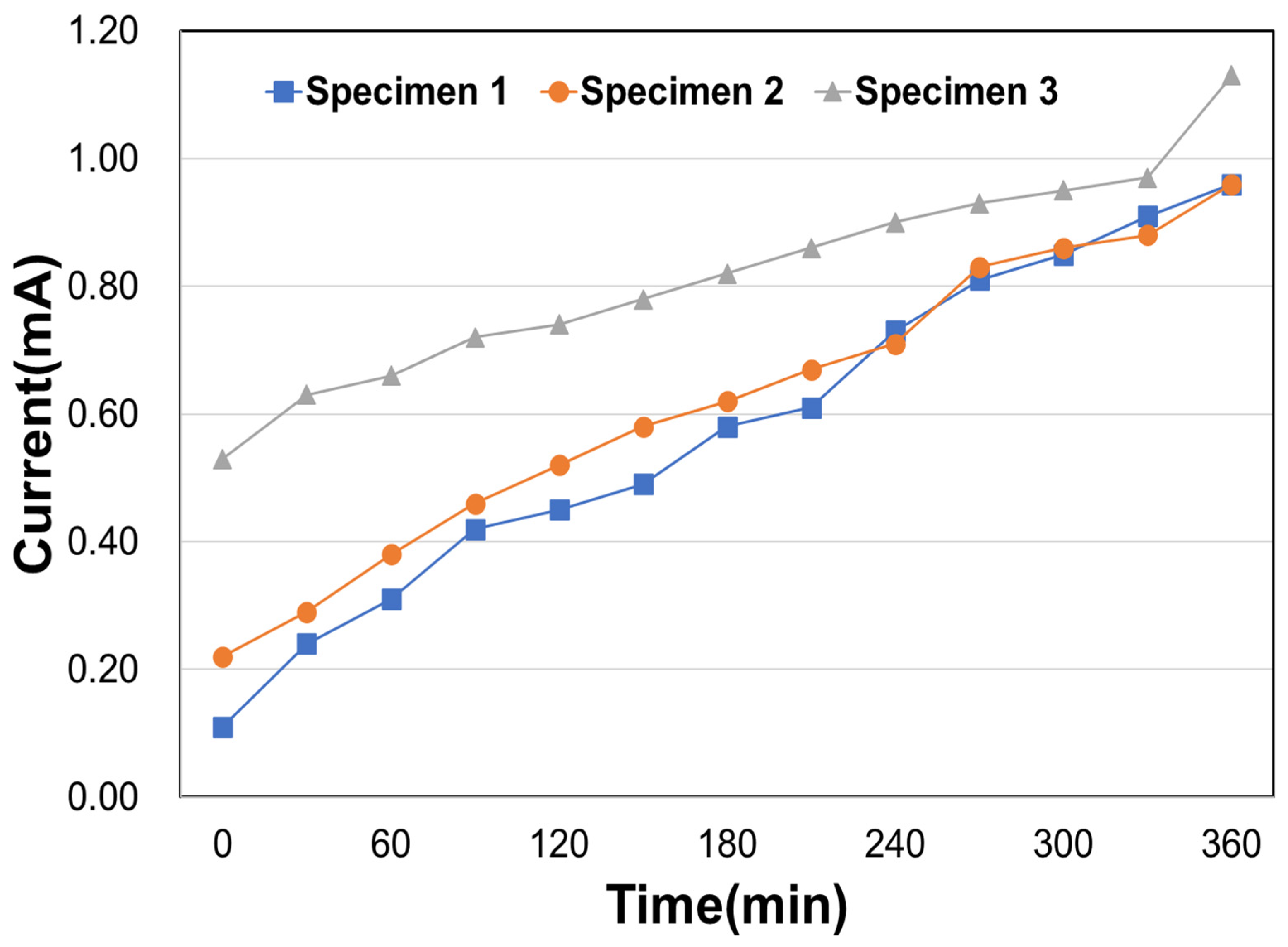
To assess the chloride resistance performance of UHPFRC, the American Society for Testing and Materials (ASTM)-C1202 standard [51] was followed, as shown in Figure 1. The chloride resistance results are summarized in Figure 2 and Table 3. Each type of specimen has a value of 12.48, 13.30, and 17.62 coulombs, with an average of 14.47 coulombs. According to ASTM C1202, values below 100 Coulombs are deemed negligible, suggesting minimal chloride damage. The dense microstructure formed by the various mineral admixtures in UHPFRC acts as a barrier against external factors, contributing to the resistance to deterioration of the concrete. Therefore, the UHPFRC in this study could be considered to have outstanding durability owing to its dense structure.
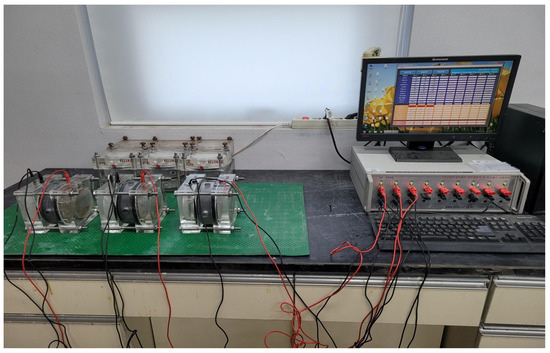
Figure 1.
Chlorine ion penetration resistance test setup.
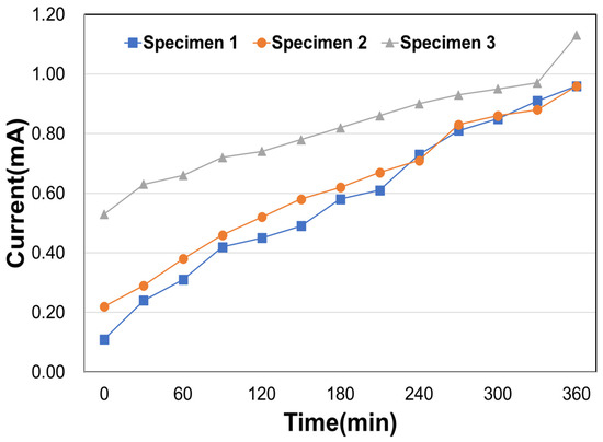
Figure 2.
Experimental results for chloride ion penetration.
Table 3.
Experimental results for chloride ion penetration.
2.4. Mechanical Properties
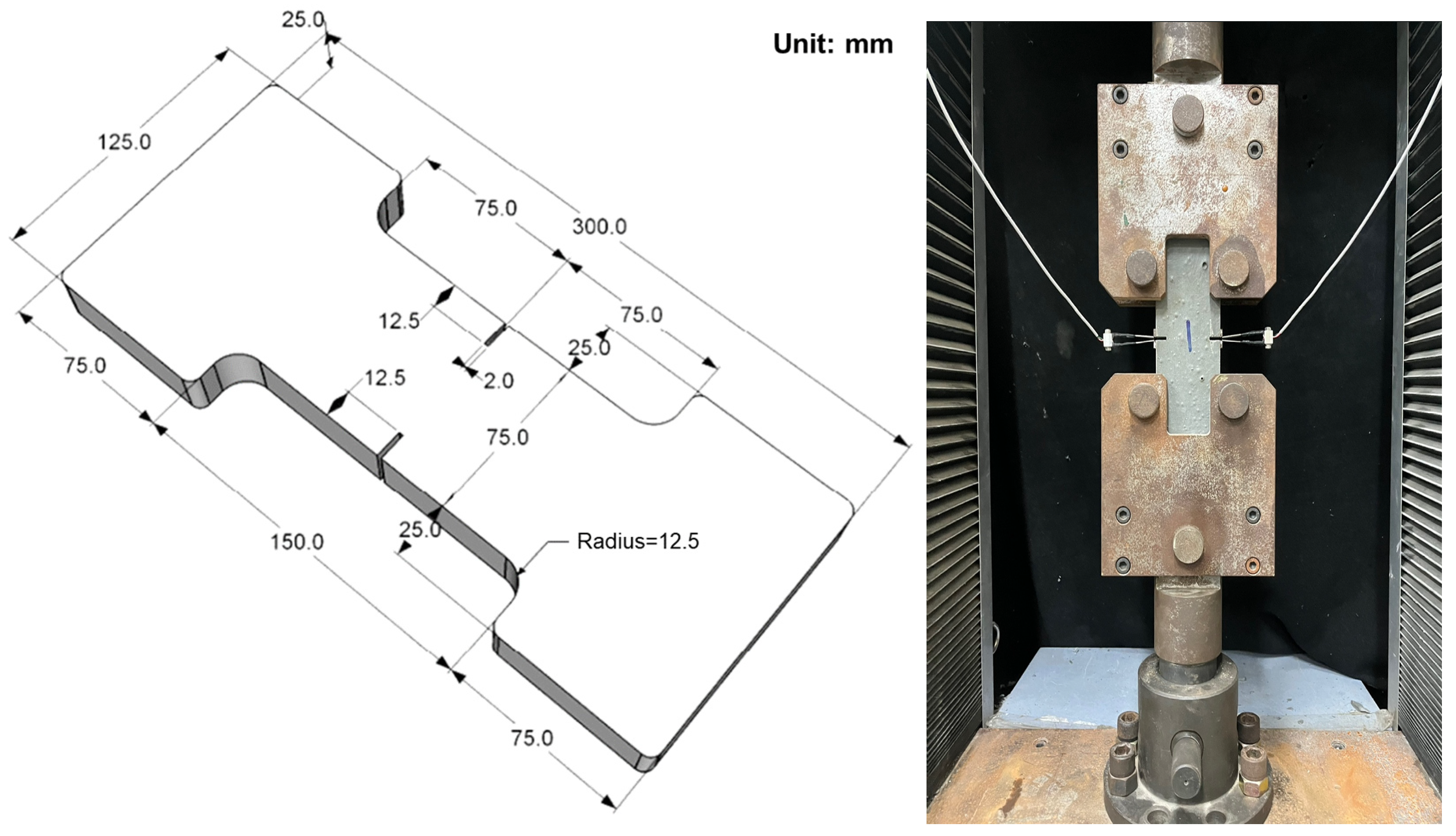
To assess the compressive strength (fck) of both NC and UHPFRC, ϕ100 cylindrical specimens were made. The compressive strength experiments were conducted based on ASTM C39M [52]. In the case of the tensile strength (ft), a splitting tensile strength experiment was conducted for NC, and a direct tensile strength experiment was conducted for UHPFRC. Both the compressive and tensile strength experiments were conducted on three specimens. The specimen used for determining the splitting tensile strength of NC was a ϕ150 cylinder, referring to ASTM C496 [53]. As shown in Figure 3, the direct tensile strength specimens were fabricated in dog-bone shapes, featuring 2 mm wide and 12.5 mm deep notches on both sides to induce cracking in the center.

Figure 3.
Dog-bone-type specimen used for the measurement of direct tensile strength.
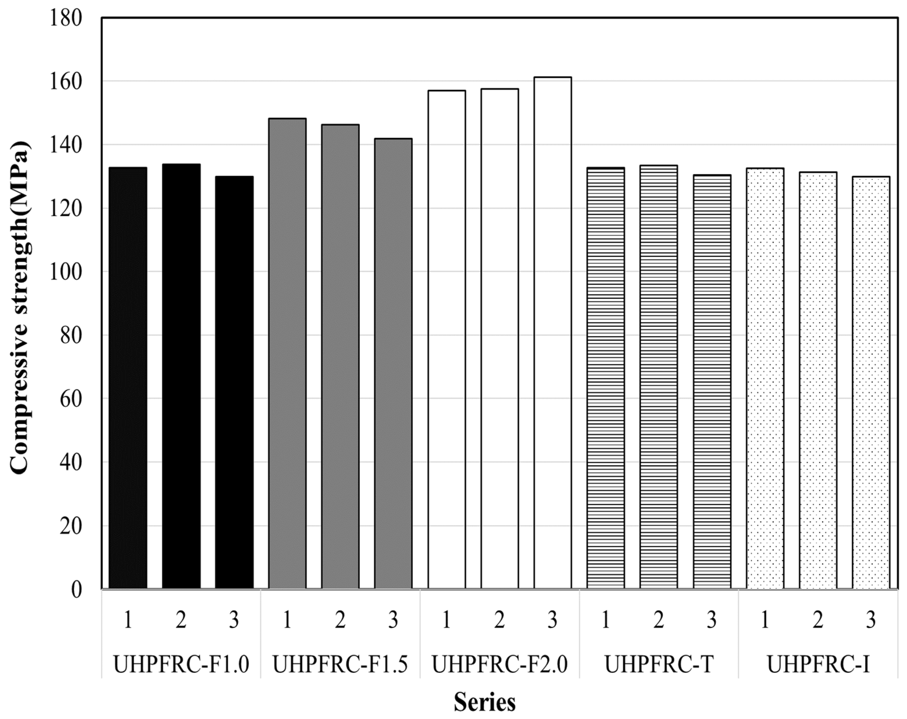
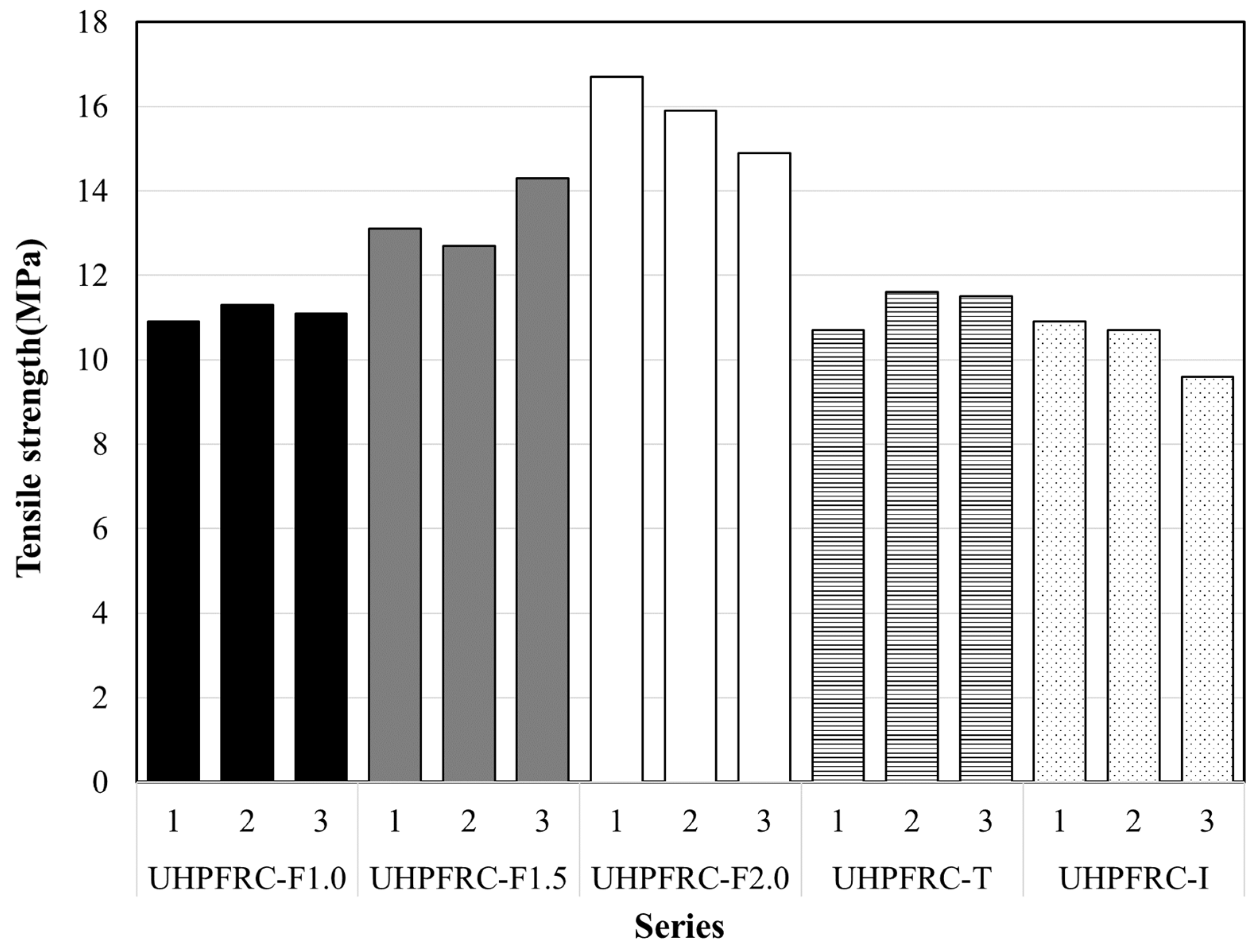
The results show that NC has an average compressive strength of 27 MPa and an average splitting tensile strength of 1.8 MPa. The average compressive strengths of the UHPFRC-F series with steel fiber contents of 1.0%, 1.5%, and 2.0% are 132, 145, and 158 MPa, respectively, and the average direct tensile strengths are 10.1, 13.6, and 15.2 MPa, respectively. For the UHPFRC-T and UHPFRC-I series, the average compressive strengths are 132 and 131 MPa, respectively, and the average direct tensile strengths are 11.6 and 11.2 MPa, respectively. The measured results for each experimental variable are illustrated in Figure 4 and Figure 5.

Figure 4.
Compressive strength results according to test parameters.
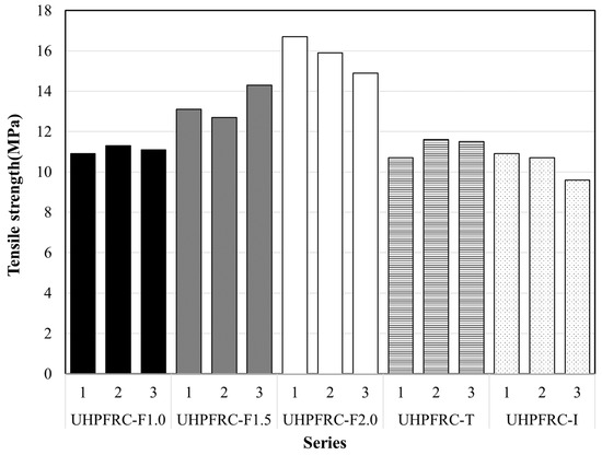
Figure 5.
Tensile strength results according to test parameters.
3. Experimental Variables and Results
3.1. Experimental Variables
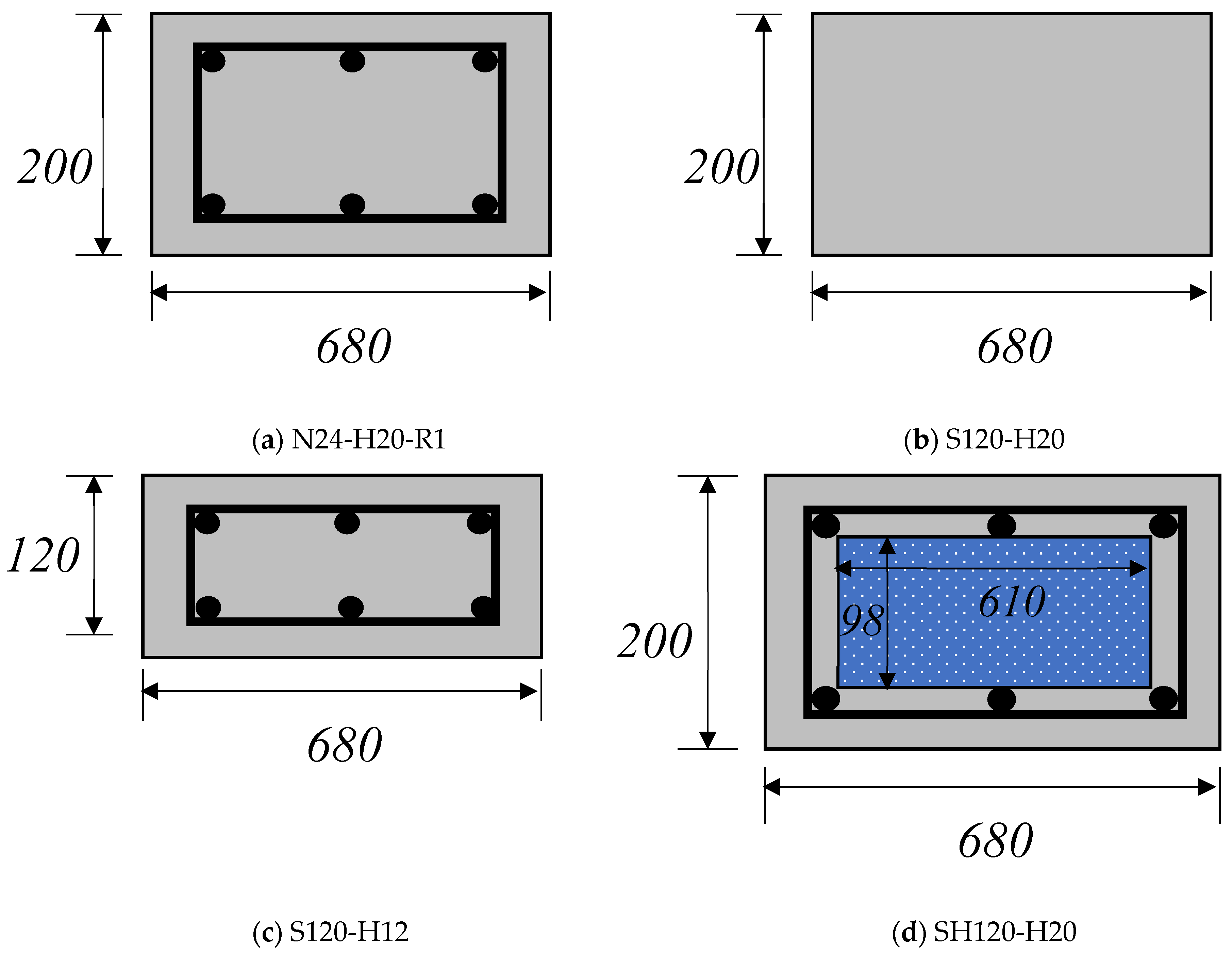
For the NC panels (N24-R1), the variables included panel thickness and rebar specifications in accordance with the Korean Concrete Wall Design Standards (KDS 14 20 72) [54]. The concrete wall thickness was set at 200 mm, with D13 and D16 rebars utilized to provide compressive and tensile strength, respectively (Figure 6a).
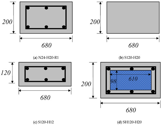
Figure 6.
Panel dimensions (mm).
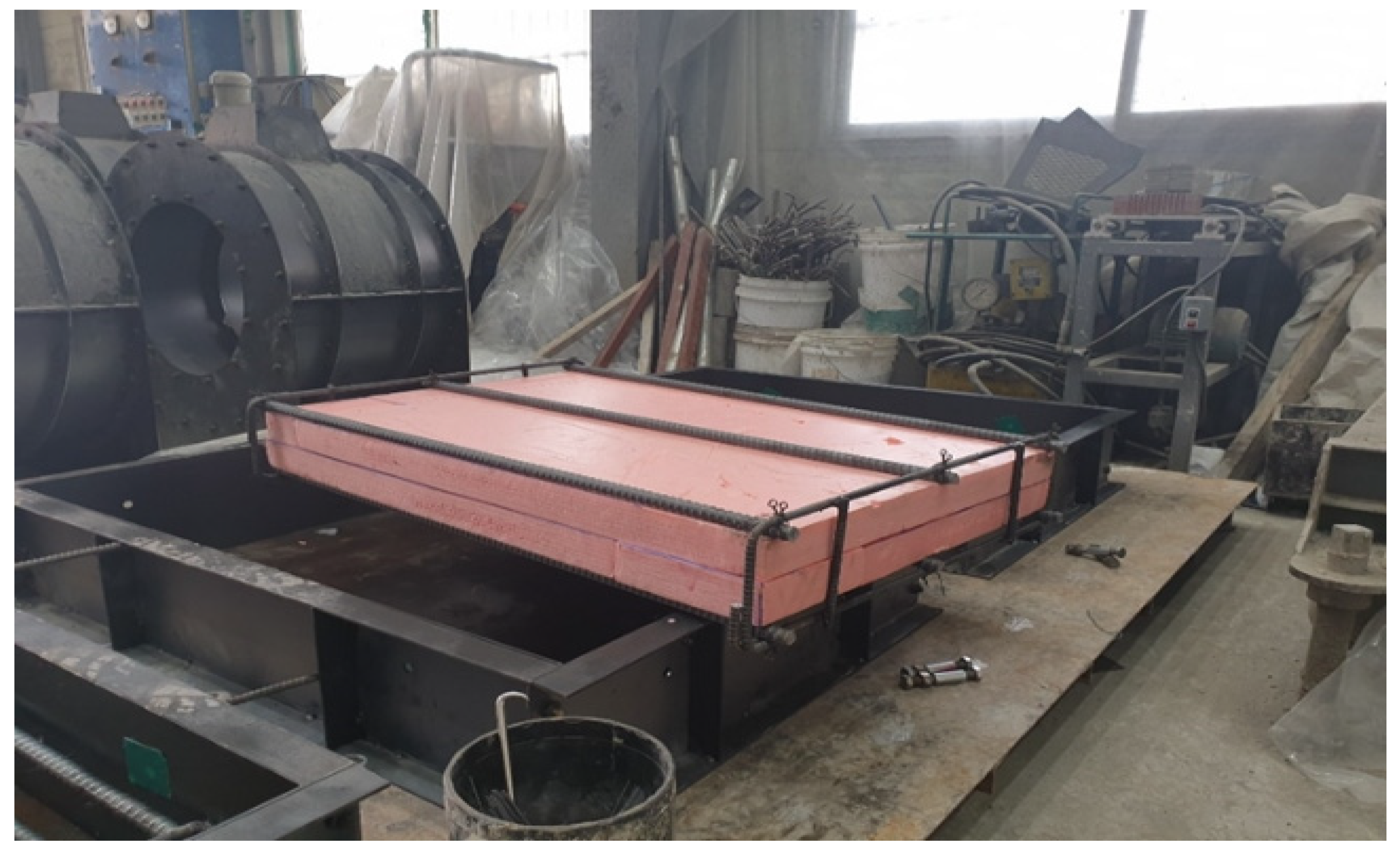
In the case of the UHPFRC panels, the variables included the steel fiber content, panel thickness, and utilization of extruded thermal insulation. A steel fiber content of 1.0%, 1.5%, or 2.0% was employed as a variable in the UHPFRC-F series, with no embedded rebar, aiming to independently assess the flexural performance of UHPFRC. In the UHPFRC-H series, the amount of rebar was varied by reducing the panel thickness from 200 mm to 120 mm and adjusting the rebar diameter to D10, D13, and D16. Additionally, extruded insulation (dimensions: 610 mm × 98 mm) was applied to the UHPFRC-based lightweight panel, as depicted in Figure 7. This insulation, known for its cost-effectiveness and energy efficiency, is commonly used for thermal insulation in various building structures. The objective was to achieve enhanced thermal insulation and reduced weight compared to conventional UHPFRC panels.
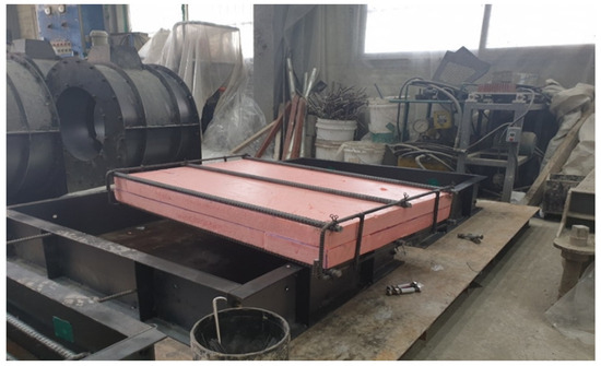
Figure 7.
Photograph showing the shape of the SH120-H20 series.
For each panel variable, wet curing was conducted for 1 d at a temperature of 20 ± 2 °C following concrete pouring. After formwork removal, high-temperature steam curing was subsequently applied for 2 d at 60 ± 10 °C for the NC members and 90 ± 5 °C for the UHPFRC panels (Table 4).
Table 4.
Mechanical and chemical characteristics for UHPC.
3.2. Experimental Method
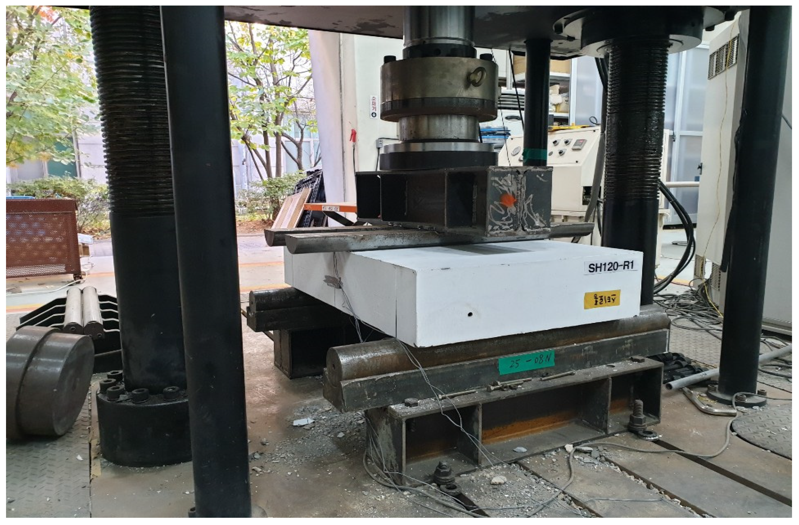
We utilized a 3000 kN loading apparatus to assess the flexural performance of the concrete panels. As depicted in Figure 8, a four-point load was applied to a 200 mm section at the center of the panel. A linear variable differential transformer (LVDT) with a 50 mm capacity was employed to measure the deflection of the panel during loading. Additionally, concrete strain gauges were fixed to the top, center, and bottom sections of the concrete panel to monitor the strain characteristics at each loading stage (Figure 9).
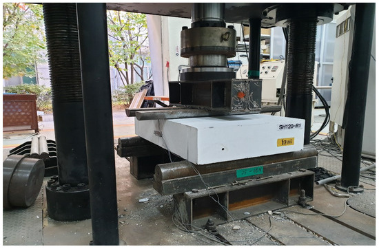
Figure 8.
Test setup.
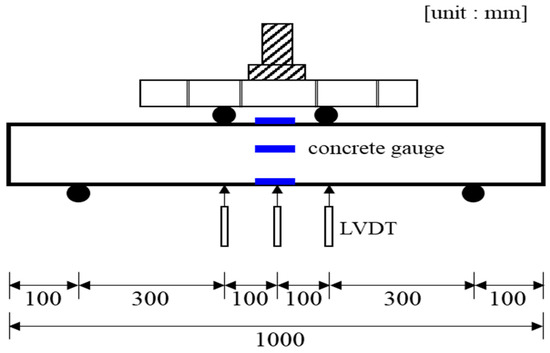
Figure 9.
Instrumentation used for the panel.
3.3. Experimental Results and Analysis
The load–deflection relationships based on the deflection measured during the application of loads on the concrete panels were compared. Table 5 provides a summary of the experimental variables and results for the concrete panels. The initial cracking load (Pcr) was determined based on the load at the end of the initial linear section and observation of initial cracks by the naked eye during load application. The point at which the load shows nonlinear behavior (after a monotonic increase) is denoted as the yield load (Py) state. The ultimate load (Pu) was calculated as the maximum load in the load–deflection relationship.
Table 5.
Test results.
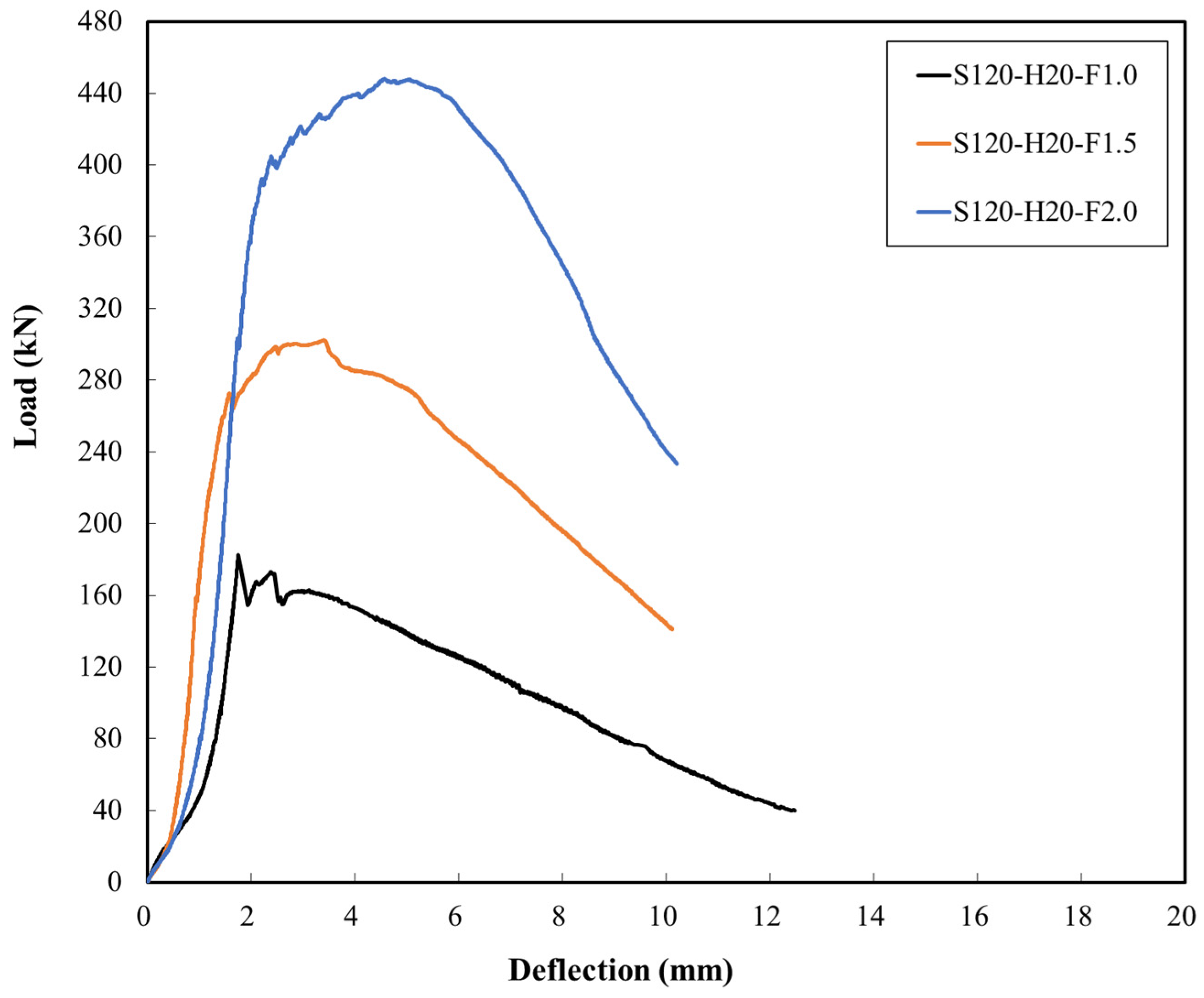
The load–deflection relationships for the UHPFRC-F series with steel fiber contents of 1.0%, 1.5%, and 2.0% are presented in Figure 10. The initial cracking loads for experimental members F1.0, F1.5, and F2.0 were 78.6, 79.8, and 79.9 kN, respectively, with Δcr values of 1.3, 1.1, and 1.1 mm, respectively. Since no rebar was embedded, yield loads were not examined. A small initial crack developed in the center cross-section of the panel member, and the load progressively increased. The ultimate loads (Pu) were 182.7, 302.3, and 448.2 kN, with deflections of 1.8, 3.4, and 4.6 mm, respectively. The analysis revealed that the ultimate load increased by 1.65 and 2.45 times compared to that of the F1.0 member as the steel fiber content increased. The load-carrying capacity of the panel member increased with increasing steel fiber content. After the ultimate load was reached, the load exhibited a gradual decrease, which was attributed to the ductility effect of the steel fibers, even without embedded rebar.

Figure 10.
Load–deflection curve (UHPFRC-F series).
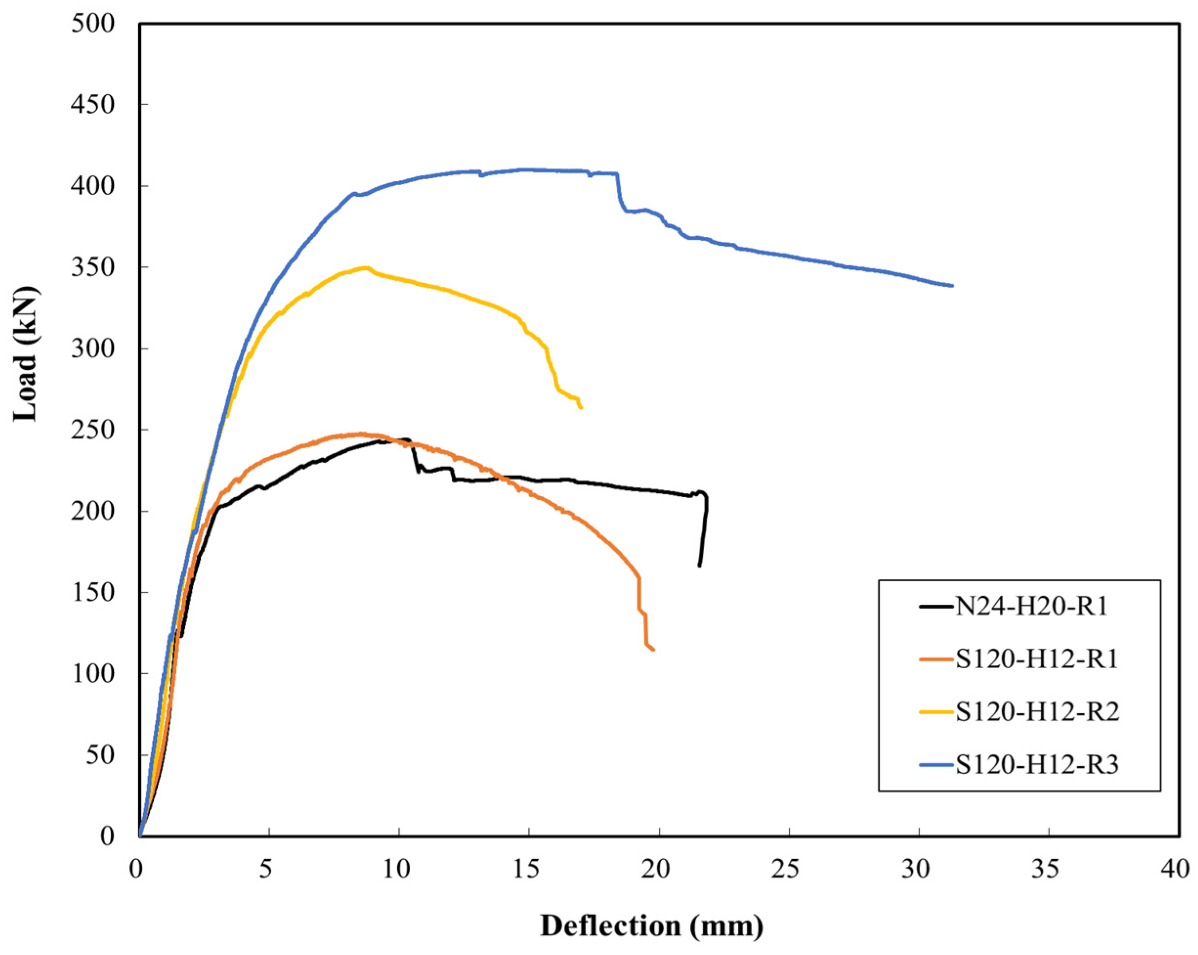
The analysis of the load–deflection relationships for the UHPFRC-T series based on the amount of rebar yielded the following results. The initial cracking loads for experimental members S120-H12-R1, S120-H12-R2, and S120-H12-R3 were 80.5, 120.9, and 96.2 kN, respectively. Correspondingly, the measured deflections were 1.2, 1.5, and 1.1 mm (Figure 11). Initial cracking was observed on the lower surface of the flexural section, and as the load increased, these cracks tended to propagate vertically along the upper surface of the member. For the S120-H12-R3 panel, which had the highest rebar content, the ultimate load was 349.8 kN, with a deflection of 8.6 mm. The ultimate load of the normal N24-H20-R1 member was 244.1 kN, and that of the S120-H12-R1 panel with the same rebar content was similar at 247.7 kN. For the normal N24-H20-R1 panel, the resistance capacity of the rebar decreased after the ultimate load was reached, leading to an expected cutting failure, which prompted termination of the test. In contrast, the UHPFRC-F series exhibited a gradual decrease in load after the ultimate load was reached because of the cross-linking effect of the steel fibers. Notably, the N24-H20-R1 member and S120-H12-R1 maintained similar performances despite the reduction in the panel thickness of approximately 49% (from 200 mm to 120 mm).
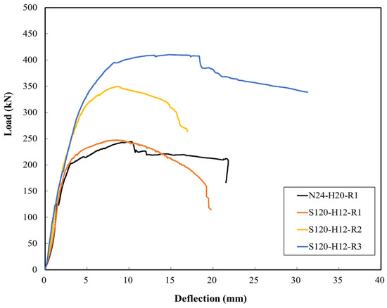
Figure 11.
Comparison of load–deflection curves of N24-H20-R1 and UHPFRC-F series specimens.
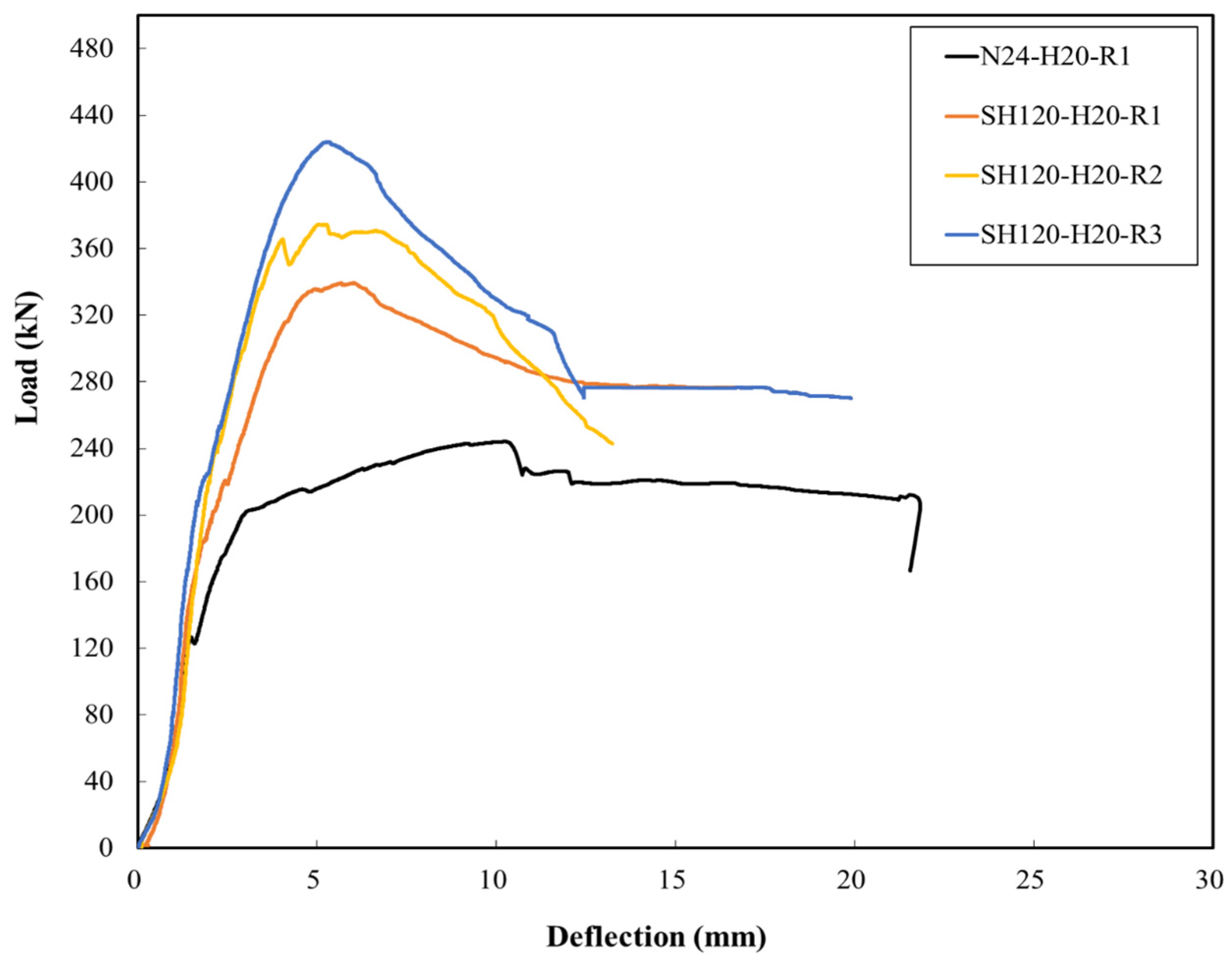
The load–deflection relationships of the NC N24-H20-R1 member and the UHPFRC-I series were analyzed, resulting in the following findings. As shown in Figure 12, the initial cracking loads of SH120-H20-R1, SH120-H20-R2, and SH120-H20-R3 were 99.1, 95.2, and 70.9 kN, respectively, with deflections of 1.2, 1.3, and 1.0 mm, respectively. The N24-H20-R1 panel exhibited nonlinear behavior after a linear increase in load, with a yield load of 201.0 kN and a deflection of 3.0 mm. In contrast, SH120-H20-R1 and SH120-H20-R2 showed yield loads of 334.5 and 363.0 kN, respectively, with deflections of 4.8 and 4.0 mm, respectively. For panel SH120-H20-R3, the yield load could not be measured as the load rapidly increased. Unlike the normal N24-H20-R1 member, the UHPC-I series demonstrated a gradual decrease in the load-carrying capacity after the ultimate load was reached due to increased deflection and widening of the main crack.

Figure 12.
Comparison of load–deflection curves obtained from N24-H20-R1 and UHPC-I series specimens.
The ductility of a concrete structure refers to its ability to undergo deformation until it fails outside the elastic range and can be used as a measure of its ability to absorb energy [55]. Generally, the ductility of concrete structures can be quantified by a ductility index. Unlike regular concrete structures, the UHPFRC structures exhibited ductility due to strain hardening from the initial crack stage. In this study, the ductility index of the test members was calculated based on the initial and ultimate states of deflection using Equation (1).
where μ represents the ductility index of the member, Δcr denotes the deflection at the initial cracking load, and Δu denotes the deflection at the ultimate load.
The ductility index of the conventional concrete specimen N24-H20-R1 was 6.44, whereas for the UHPFRC-T series, the ductility indices for S120-H12-R1, S120-H12-R2, and S120-H12-R3 were 7.08, 4.93, and 7.81, respectively. Except for the SH-H12-R2 specimen, the ductility index increased by 10% to 37% compared to that of the conventional concrete specimen. Additionally, for the UHPFRC-I series, the ductility indices for SH120-H20-R1, SH120-H20-R2, and SH120-H20-R3 were 5.00, 3.92, and 5.30, respectively, demonstrating lower values than that of the conventional concrete specimen.
As shown in Figure 6, considering the cross-section of the specimen with the insulation material, the neutral axis, which plays a significant role in ductility, was formed in the insulation material. In other words, while in the regular UHPFRC specimen, the resistance against bending due to material deformation was demonstrated by the fiber-reinforced concrete, in the specimen with the insulation material, the insulation became the primary contributor. Therefore, the ductility effect could be inferred to be diminished in the specimen with the insulation material.
Using UHPFRC, the flexural performance was evaluated by selecting the steel fiber content, panel thickness, and thermal insulation as the primary variables.
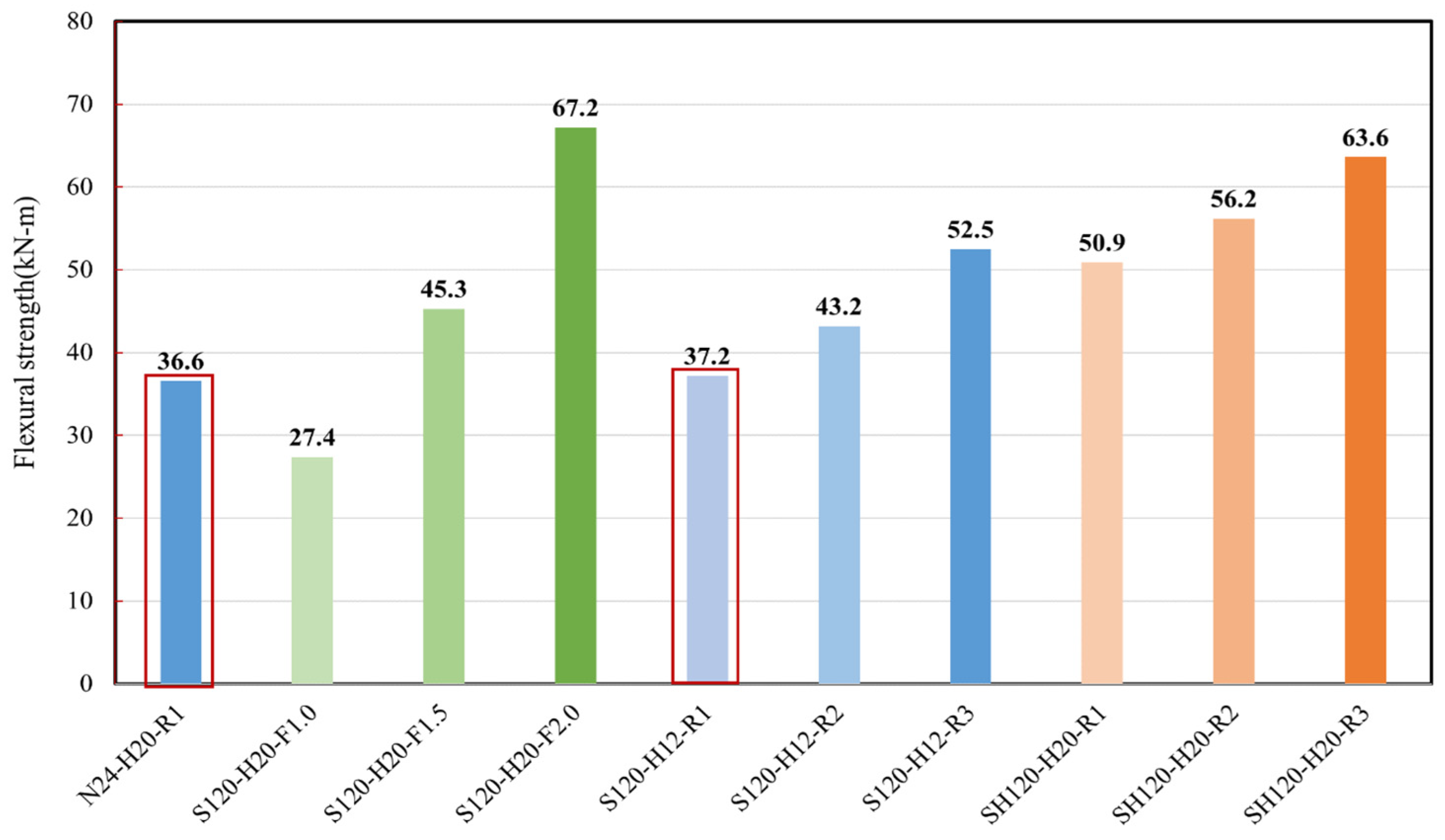
Overall, the flexural strength of the UHPFRC members, except for the F1.0 member of the UHPFRC-F series, was greater than that of the NC member N24-H20-R1. The N24-H20-R1 member weighed 0.34 t, while the UHPFRC-T series and UHPFRC-I series weighed 0.20 t each, indicating a reduction of approximately 40% in the amount of concrete used. A member with a flexural strength similar to that of an NC panel, while ensuring the workability and economic feasibility of concrete, was considered for the optimal cross-section. As illustrated in Figure 13, we concluded that the S120-H12-R1 member of the UHPFRC-T series had the optimal cross-section. Therefore, in terms of the main variables determining the optimal cross-section of the UHPFRC modular panels in this study, the design reference compressive strength is 120 MPa, the panel thickness is 120 mm, and the longitudinal rebar diameter is D10.
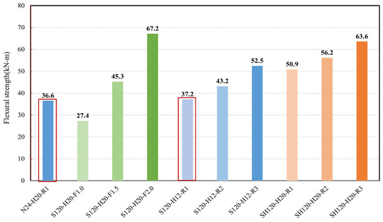
Figure 13.
Comparison of flexural strengths of various specimens tested in this study.
4. Evaluation of the UHPFRC Single-Story Modular House Manufacturability
4.1. Basic Review of the UHPFRC Modular Structure
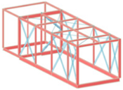
In this study, the structural design criteria considered for the UHPFRC modular unit included the characteristics, scale, ground and site conditions, and economic feasibility of the concrete modular structures. The design followed the Structural Design Guidelines of Fiber-reinforced SUPER Concrete (2019) [48] and the Concrete Structure Design Standards (KDS 14 20 72) [54]. As depicted in Figure 14, the initial design encompassed a four-story apartment building using the stacked modular construction method. In this approach, the frame is manufactured in a factory, while installation and assembly occur onsite. A single modular unit, designed with a width of 3.37 m and a length of 10.5 m, ensured easy transportation. The design allowed for flexibility in adapting to varying vehicle passage widths based on country- or region-specific regulations. The maximum transportable load was determined to be 27.5 tf, and with a self-weight per modular unit of 26.7 tf, the unit could be efficiently transported.
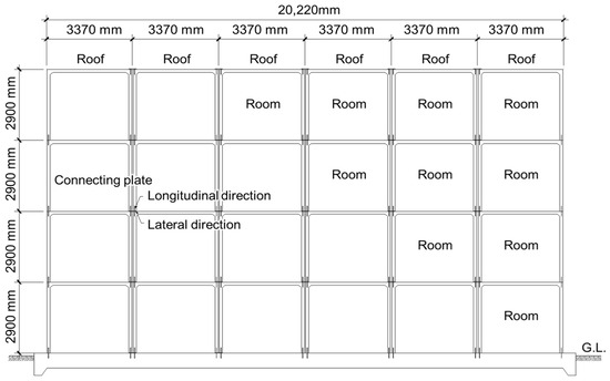
Figure 14.
Modular structure of the tested design.
4.2. Design Loads and Materials Used
The design loads considered in this study included dead, live, and wind loads. The dead load was selected to encompass basic framing loads, permanent fixtures, and building finishes. The live loads were set at 1.0 kN/m2 for the roof and 2.0 kN/m2 for the bedroom and living room spaces. The wind loads were determined based on the basic wind velocity (V0) of 25.4 m/s, importance factor (Iw) of 0.95, and wind topographic factor (Kzt) of 1.0 in a local area. The material properties, including the reference compressive strength of the concrete (120 MPa), elastic modulus (41 GPa), reference cracking tensile strength (fcrk) of 4.6 MPa, reference tensile strength (fctk) of 7.0 MPa, material modulus of 0.80, and unit weight of 25.5 kN/m2, were adopted from the Structural Design Guidelines of Fiber-reinforced SUPER Concrete (2019) [48]. The yield strength of the rebar used was 400 MPa.
4.3. Modeling for Structural Analysis
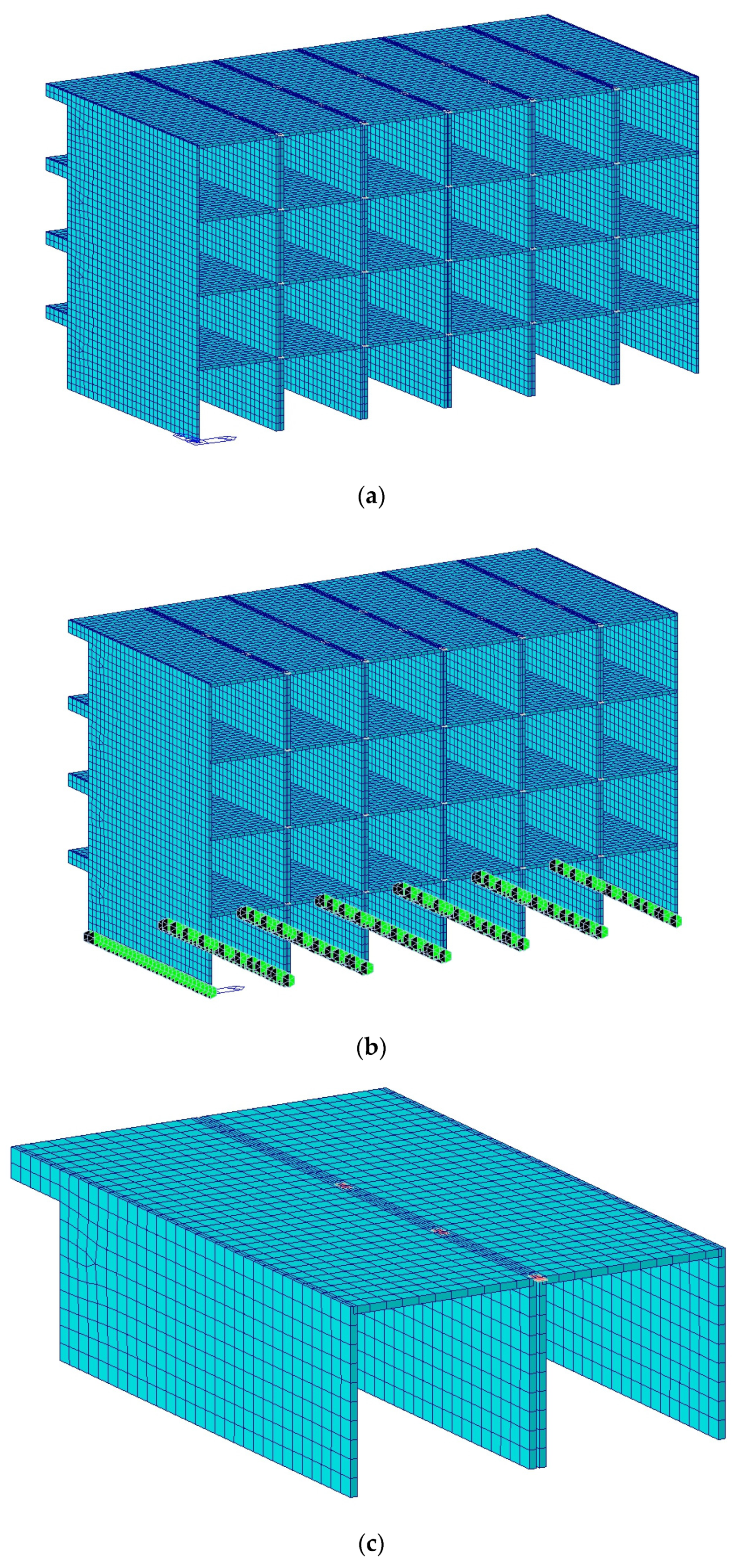
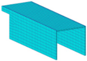
In this study, structural analysis was conducted assuming a four-story residential building consisting of six sections. As shown in Figure 15, each unit module was 3.37 m wide, 10.5 m long, and 2.9 m high. Structural modeling was performed using plate elements with a thickness of 120 mm for walls, slabs, and beams. Additionally, horizontal connections between modules were established using steel plates with a width of 300 mm and a thickness of 20 mm. The foundation and vertical joints between modules were constrained only in terms of displacement using PIN joints. However, the horizontal connections between modules were represented by beam elements composed of connecting steel plates. Structural analysis of this modular housing was conducted using Midas Gen.
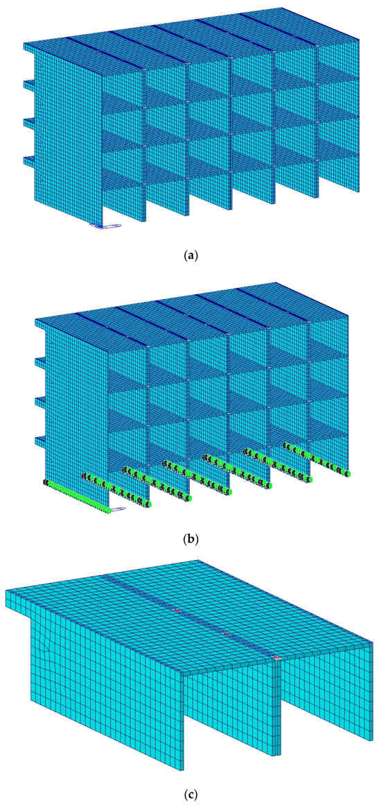
Figure 15.
The structural modeling for modular housing. (a) modeling; (b) boundary condition (foundation and joint); (c) boundary condition (horizontal joint).
4.4. Stress Review
Based on the examination conducted on the 1st-floor module where maximum stresses occurred due to vertical and horizontal loads, as depicted in Figure 16, the compressive stress satisfied the criterion, measuring 96 MPa and surpassing the required 18.5 MPa. Additionally, the building displacement for the wind load (V0 = 26 m/s) met the usability standards in both the X and Y directions. However, the seismic load indicated a tensile stress requirement of 9.9 MPa at the lower part of the building, but this value was observed to be 5.6 MPa, indicating the need for reinforced steel. This was due to an insufficient evaluation for seismic conditions, causing a deficiency in the tensile stress at the lower levels. Consequently, for multistory residential structures, rather than single-story modular structures, careful consideration of the tensile stress at the lower levels is necessary. Moreover, the maximum shear stress was computed as 169.3 kN, which was adequate for structural safety. Proposal of further research on the impact of vibration and noise on each floor slab, as well as suggestions for connections between modular components and methods for integration, is planned.
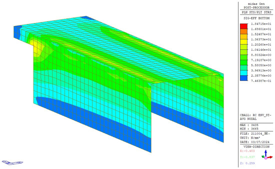
Figure 16.
Stress analysis results.
4.5. Fabrication of a Single-Story Modular Structure
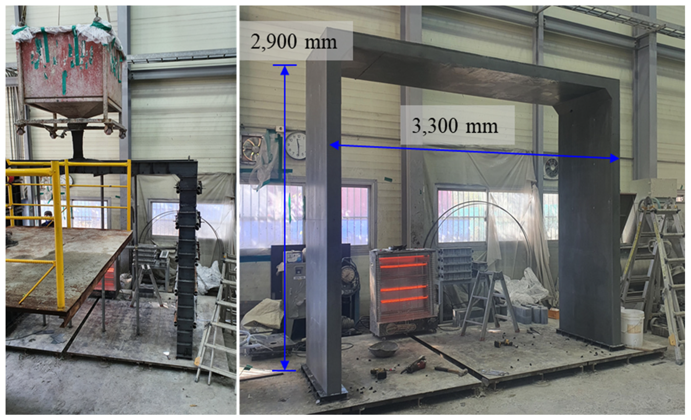
The optimal UHPFRC panel developed in this study was applied to construct a single-story modular prototype. The dimensions of the fabricated UHPFRC modular unit were 2900 mm high, 3300 mm wide, and 1000 mm long. Initially, the steel panels were machined, with the formwork fabrication and rigid-joint conditions applied to ensure that the panels could withstand lateral pressures. Concrete was poured from left to right in the upper part, considering the flowability of UHPFRC [56]. Haunches were installed to prevent cracking due to stress concentration on the outer part of the upper slab. In addition, concrete was poured in the left to right direction for the upper slab length of 1000 mm to prevent balling of steel fibers. Figure 17 illustrates the fabrication process of the UHPFRC modular prototype.
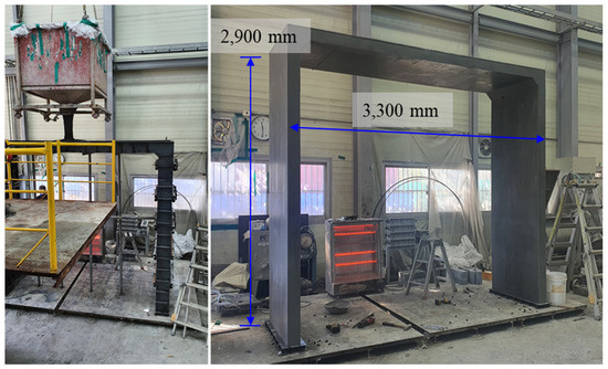
Figure 17.
Fabrication of the UHPC modular prototype UHPC.
5. Economic Feasibility Analysis of the Modular House
An economic feasibility analysis was conducted by comparing the UHPFRC modular unit with a steel-structure modular house unit. The building module dimensions were 3320 mm wide, 2900 mm high, and 10,500 mm long. Construction costs were analyzed for materials such as concrete and steel without factoring in labor and equipment costs.
As presented in Table 6, the building cost of the UHPFRC modular unit was compared to that of a steel structure (infill method). The UHPFRC modular unit cost was USD 7614, whereas the steel modular technology cost was USD 9370, indicating an 18.7% cost reduction. This analysis highlighted the significant impact of steel prices (USD 3000/t) on the economic feasibility of modular units in steel-structure construction, considering recent increases in raw material costs for construction.
Table 6.
Comparison of economic feasibility.
6. Conclusions
This study was conducted to develop modular buildings in the form of unit boxes using UHPFRC. Structural performance evaluation, structural analysis, and economic assessment of UHPFRC modular buildings that can replace conventional steel structures were performed. The conclusions of this study are as follows:
- To develop UHPFRC-based modular members, the flexural performance of NC elements and that of UHPFRC-F, UHPFRC-T, and UHPFRC-I series were evaluated. The results indicated that in UHPFRC modular structures, concrete usage could be reduced by up to 40–60% compared to that in modules with NC. However, ensuring structural safety while achieving similar performance and ductility effects as NC is crucial. The flexural strength of the N24-H20-R1 element was evaluated as 36.6 kN-m, while the S120-H12-R1 element exhibited a flexural strength of 37.2 kN-m. Their ductility indices were 6.44 and 7.08, respectively, showing similar flexural performances. Hence, the primary variables determining the optimal cross-section of the UHPFRC modular member were designated as follows: design compressive strength of 120 MPa, thickness of 120 mm for the member, and longitudinal rebar diameter of D10.
- To fabricate a modular structure based on UHPFRC, structural assessments were conducted for a total of 6 sections, 4 stories high, with each unit module 3.37 m in width, 10.5 m in length, and 2.9 m in height. Basic structural assessments, including bending and shear, were carried out solely to verify the constructability of the unit modules. An initial module was manufactured with dimensions of 3.3 m in width, 2.9 m in height, and 1.0 m in length utilizing UHPFRC to confirm the feasibility of implementation.
- An analysis was conducted on the construction costs of modular structures using UHPFRC compared to those of structures employing steel. The results indicated an approximately 18.7% reduction in construction costs for UHPFRC modular structures compared to steel structures (using the infill method). Recent increases in raw material prices have notably affected the economics, particularly the price of steel in steel-structure modular constructions, which was found to be a significant factor, reaching USD 3000 per ton. Considering the volatility in steel prices, economic feasibility could be ensured up to 70% of the current steel price. The application of UHPFRC in modular structures appears to be adaptable to various construction environments. However, detailed studies regarding the productivity of units of UHPFRC modular structures, connections, and seismic considerations were deemed necessary.
Author Contributions
Conceptualization, K.K. (Kyongchul Kim) and K.K. (Kyungtaek Koh); methodology, K.K. (Kyongchul Kim) and G.R.; investigation, K.L. and Y.Y.; data curation, K.L. and Y.Y.; writing—original draft preparation, K.K. (Kyongchul Kim) and G.R.; writing—review and editing, K.K. (Kyongchul Kim) and K.L.; supervision, K.K. (Kyungtaek Koh); funding acquisition, K.K. (Kyungtaek Koh). All authors have read and agreed to the published version of the manuscript.
Funding
Research for this paper was carried out under the KICT Research Program (20240097-001, Research on the Establishment for Integration and Linkage of Infrastructure for the Co-prosperity of South and North Korea) funded by the Ministry of Science and ICT.
Institutional Review Board Statement
Not applicable.
Informed Consent Statement
Not applicable.
Data Availability Statement
Data are contained within the article.
Conflicts of Interest
The authors declare no conflicts of interest.
References
- Blismas, N.; Christine, C.; Gibb, A. Benefit evaluation for off-site production in construction. Con. Manag. Econ. 2006, 24, 121–130. [Google Scholar] [CrossRef]
- Gibb, A.; Isack, F. Re-engineering through pre-assembly: Client expectations and drivers. Build. Res. Inf. 2003, 31, 146–160. [Google Scholar] [CrossRef]
- Pan, W.; Alistair, G.F.; Gibb, A.; Dainty, A.R. Leading UK housebuilders’ utilization of offsite construction methods. Build. Res. Inf. 2008, 36, 56–67. [Google Scholar] [CrossRef]
- Sun, Y.; Wang, J.; Wu, J.; Shi, W.; Ji, D.; Wang, X.; Zhao, X. Constraints hindering the development of high-rise modular buildings. Appl. Sci. 2020, 10, 7159. [Google Scholar] [CrossRef]
- Zhang, X.; Skitmore, M. Industrialized housing in China: A coin with two sides. Int. J. Strateg. Prop. Manag. 2012, 16, 143–157. [Google Scholar] [CrossRef]
- Lawson, R.M.; Ogden, R.G.; Bergin, R. Application of modular construction in high-rise buildings. J. Archit. Eng. 2012, 18, 148–154. [Google Scholar] [CrossRef]
- Kamali, M.; Hewage, K. Life cycle performance of modular buildings: A critical review. Renew. Sustain. Energy Rev. 2016, 62, 1171–1183. [Google Scholar] [CrossRef]
- Boafo, F.E.; Kim, J.H.; Kim, J.T. Performance of modular prefabricated architecture: Case study-based review and future pathways. Sustainability 2016, 8, 558. [Google Scholar] [CrossRef]
- Li, X.; Yi, W.; Chi, H.L.; Wang, X.; Chan, A.P. A critical review of virtual and augmented reality (VR/AR) applications in construction safety. Autom. Constr. 2018, 86, 150–162. [Google Scholar] [CrossRef]
- Ho, K.M.; Lam, J.P.; Max, S. Pre-Fabricated Pre-Finished Volumetric Construction (PPVC) for Residential Projects; Threesixty Cost Management Pte Ltd.: Bukit Merah, Singapore, 2018. [Google Scholar]
- Chen, K.; Lu, W. Design for manufacture and assembly oriented design approach to a curtain wall system: A case study of a commercial building in Wuhan, China. Sustainability 2018, 10, 2211. [Google Scholar] [CrossRef]
- Hu, X.; Chong, H.Y.; Wang, X. Sustainability perceptions of off-site manufacturing stakeholders in Australia. J. Clean. Prod. 2019, 227, 346–354. [Google Scholar] [CrossRef]
- Prabowo, P.A. Multi-storey modular cold-formed steel building in Hong Kong: Challenges & opportunities. IOP Conf. Ser. Mater. Sci. Eng. 2019, 650, 012033. [Google Scholar]
- Generalova, E.M.; Generalov, V.P.; Kuznetsova, A.A. Modular buildings in modern construction. Procedia Eng. 2016, 153, 167–172. [Google Scholar] [CrossRef]
- Said, H.; Ali, A.R.; Alshehri, A. Analysis of the Growth Dynamics and Structure of Modular Building Construction Industry. Cons. Res. Congr. 2014, 1977–1986. [Google Scholar]
- Abdul Nabi, M.; El-adaway, I.H. Modular Construction: Determining Decision-Making Factors and Future Research Needs. J. Manag. Eng. 2020, 36, 04020085. [Google Scholar] [CrossRef]
- Goodier, C.; Gibb, A. Future opportunities for offsite in the UK. Constr. Manag. Econ. 2007, 25, 585–595. [Google Scholar] [CrossRef]
- Kamar, K.; Azman, M.; Nawi, M. IBS Survey 2010: Drivers, barriers and critical success factors in adopting industrialised building system (Ibs) Construction by G7 contractors in Malaysia. J. Eng. Sci. Technol. 2014, 9, 490–501. [Google Scholar]
- Steinhardt, D.A.; Manley, K. Adoption of prefabricated housing-the role of country context. Sustain. Cities Soc. 2016, 22, 126–135. [Google Scholar] [CrossRef]
- Tam, V.W.; Fung, I.W.; Sing, M.C.; Ogunlana, S.O. Best practice of prefabrication implementation in the Hong Kong public and private sectors. J. Clean. Prod. 2015, 109, 216–231. [Google Scholar] [CrossRef]
- Hampson, K.D.; Brandon, P. Construction 2020: A Vision for Australia’s Property and Construction Industry; Cooperative Research Centre for Construction Innovation: Brisbane, Australia, 2004. [Google Scholar]
- Kim, J.H.; Park, I.K. The Practical Application of Modular Construction for Residential Facilities. J. Korean Hous. Assoc. 2013, 24, 19–26. [Google Scholar] [CrossRef]
- Liu, C.; Fang, D.; Zhao, L.; Zhou, J. Seismic fragility estimates of steel diagrid structure with performance-based tests for high-rise buildings. J. Build. Eng. 2022, 52, 104459. [Google Scholar] [CrossRef]
- Lee, D.Y.; Cho, B.H.; Hong, P.G.; Ha, T.H. Seismic performance evaluation of beam-column connection of unitized floor system. J. Korean Soc. Steel Constr. 2019, 31, 85–96. [Google Scholar] [CrossRef]
- Narayanan, N.; Ramamurthy, K. Structure and properties of aerated concrete: A review. Cem. Concr. Compos. 2000, 22, 321–329. [Google Scholar] [CrossRef]
- Adhikary, S.K.; Rudžionis, Ž.; Tučkutė, S. Characterization of novel lightweight self-compacting cement composites with incorporated expanded glass, aerogel, zeolite and fly ash. Case Stud. Constr. Mater. 2022, 16, e00879. [Google Scholar] [CrossRef]
- Altalabani, D.; Linsel, S.; Bzeni, D.K. Rheological properties and strength of polypropylene fiber-reinforced self-compacting lightweight concrete produced with ground limestone. Arab. J. Sci. Eng. 2020, 45, 4171–4185. [Google Scholar] [CrossRef]
- Muthusamy, S.; Kolandasamy, P. Samozbijajući lagani beton na visokim temperaturama. Građevinar 2015, 67, 329–338. [Google Scholar]
- Ranjbar, N.; Behnia, A.; Alsubari, B.; Birgani, P.M.; Jumaat, M.Z. Durability and mechanical properties of self-compacting concrete incorporating palm oil fuel ash. J. Clean. Prod. 2016, 112, 723–730. [Google Scholar] [CrossRef]
- Sabet, F.A.; Libre, N.A.; Shekarchi, M. Mechanical and durability properties of self consolidating high performance concrete incorporating natural zeolite, silica fume and fly ash. Constr. Build. Mater. 2013, 44, 175–184. [Google Scholar] [CrossRef]
- Ke, Y.; Beaucour, A.L.; Ortola, S.; Dumontet, H.; Cabrillac, R. Influence of volume fraction and characteristics of lightweight aggregates on the mechanical properties of concrete. Const. Build. Mater. 2009, 23, 2821–2828. [Google Scholar] [CrossRef]
- Real, S.; Gomes, M.G.; Rodrigues, A.M.; Bogas, J.A. Contribution of structural lightweight aggregate concrete to the reduction of thermal bridging effect in buildings. Const. Build. Mater. 2016, 121, 460–470. [Google Scholar] [CrossRef]
- Roberz, F.; Loonen, R.C.G.M.; Hoes, P.; Hensen, J.L.M. Ultra-lightweight concrete: Energy and comfort performance evaluation in relation to buildings with low and high thermal mass. Energy Build. 2017, 138, 432–442. [Google Scholar] [CrossRef]
- Abbass, A.A.; Abid, S.R.; Arna’ot, F.H.; Al-Ameri, R.A.; Özakça, M. Flexural response of hollow high strength concrete beams considering different size reductions. Structures 2020, 23, 69–86. [Google Scholar] [CrossRef]
- Bai, Z.Z.; Au, F.T.K. Flexural ductility design of high-strength concrete columns. Struct. Des. Tall Spec. Build. 2013, 22, 92–115. [Google Scholar] [CrossRef]
- Koziński, K.; Winnicki, A. Experimental research and analysis of load capacity and deformability of slender high strength concrete columns in biaxial bending. Eng. Struct. 2016, 107, 47–65. [Google Scholar] [CrossRef]
- Taheri, A.; Tasnimi, A.A.; Moghadam, A.S. Experimental investigation on the seismic behavior and damage states of reinforced high strength concrete columns. Structures 2020, 27, 163–173. [Google Scholar] [CrossRef]
- Kim, K.C.; Yang, I.H.; Joh, C. Effects of single and hybrid steel fiber lengths and fiber contents on the mechanical properties of high-strength fiber-reinforced concrete. Adv. Civil Eng. 2018, 2018, 7390798. [Google Scholar] [CrossRef]
- Shaikh, F.U.A.; Luhar, S.; Arel, H.Ş.; Luhar, I. Performance evaluation of Ultrahigh performance fibre reinforced concrete—A review. Const. Build. Mater. 2020, 232, 117152. [Google Scholar] [CrossRef]
- Li, J.; Wu, Z.; Shi, C.; Yuan, Q.; Zhang, Z. Durability of ultra-high performance concrete—A review. Const. Build. Mater. 2020, 255, 119296. [Google Scholar] [CrossRef]
- Harsono, K.; Shih, S.G.; Chen, Y.J. The Integration of Design and Fabrication for Prefabricated UHPC Panels of Building Facades. In Proceedings of the 5th International Conference on Civil and Building Engineering Informatics, Bangkok, Thailand, 19–21 July 2023; pp. 444–451. [Google Scholar]
- Ding, R.; Sun, Y.T.; Nie, X.; Chen, D.Q. Experimental study on seismic behavior of an unreinforced precast wall-slab structure based on UHPC sandwich panels. J. Build. Eng. 2023, 68, 106197. [Google Scholar] [CrossRef]
- Li, Z.; Chen, D.; Feng, X.; Chen, J.F. Hydroelastic analysis and structural design of a modular floating structure applying ultra-high performance fiber-reinforced concrete. Ocean Eng. 2023, 277, 114266. [Google Scholar] [CrossRef]
- Lu, J.X.; Ali, H.A.; Jiang, Y.; Guan, X.; Shen, P.; Chen, P. A novel high-performance lightweight concrete prepared with glass-UHPC and lightweight microspheres: Towards energy conservation in buildings. Compos. Part B 2022, 247, 110295. [Google Scholar] [CrossRef]
- Seo, E.A.; Kim, W.W.; Kim, S.K.; Kwon, H.K.; Lee, H.J. Mechanical properties of 3D printed concrete with coarse aggregates and polypropylene fiber in the air and underwater environment. Const. Build. Mater. 2023, 378, 131184. [Google Scholar] [CrossRef]
- Katzer, J.; Skoratko, A. Using 3D printed formworks for the creation of steel fibre reinforced concrete-plastic columns. Const. Build. Mater. 2022, 337, 127586. [Google Scholar] [CrossRef]
- Hematibahar, M.; Hasanzadeh, A.; Vatin, N.I.; Kharun, M.; Shooshpasha, I. Influence of 3D-printed reinforcement on the mechanical and fracture characteristics of ultra high performance concrete. Results Eng. 2023, 19, 101365. [Google Scholar] [CrossRef]
- KCI (Korea Concrete Institute). The Structural Design Guideline of the Fiber Reinforced SUPER Concrete; KCI: Seoul, Republic of Korea, 2019. [Google Scholar]
- Shin, H.O.; Yoo, D.Y.; Lee, J.H.; Lee, S.H.; Yoon, Y.S. Optimized mix design for 180 MPa ultra-high-strength concrete. J. Mater. Res. Technol. 2019, 8, 4182–4197. [Google Scholar] [CrossRef]
- Tan, L.; Yang, J.; Li, C.; Zhang, G.; Ding, Q.; Sun, D.; Zhang, Y. Effect of Polyoxymethylene Fiber on the Mechanical Properties and Abrasion Resistance of Ultra-High-Performance Concrete. Materials 2023, 16, 7014. [Google Scholar] [CrossRef]
- ASTM C1202-22; Standard Test Method for Electrical Indication of Concrete’s Ability to Resist Chloride Ion Penetration. ASTM International: West Conshohocken, PA, USA, 2022.
- ASTM C39M-21; Standard Test Method for Compressive Strength of Cylindrical Concrete Specimens. ASTM International: West Conshohocken, PA, USA, 2021.
- ASTM C496-96; Standard Test Method for Splitting Tensile Strength of Cylindrical Concrete Specimens. ASTM International: West Conshohocken, PA, USA, 2017.
- KDS 14 20 72:2016; Concrete Wall Design Code. Korean Concrete Institute(KCI): Seoul, Republic of Korea, 2016.
- Kim, K.C.; Yang, I.H.; Joh, C. Material properties and structural characteristics on flexure of steel fiber-reinforced ultra-high-performance concrete. J. Korea Concr. Inst. 2016, 28, 177–185. [Google Scholar] [CrossRef]
- Yang, I.H.; Kim, K.C.; Joh, C.B. Structural Behavior of Hybrid Steel Fiber-Reinforced Ultra High Performance Concrete Beams Subjected to Bending. J. Korea Concr. Inst. 2014, 26, 771–778. [Google Scholar] [CrossRef]


Disclaimer/Publisher’s Note: The statements, opinions and data contained in all publications are solely those of the individual author(s) and contributor(s) and not of MDPI and/or the editor(s). MDPI and/or the editor(s) disclaim responsibility for any injury to people or property resulting from any ideas, methods, instructions or products referred to in the content. |
© 2024 by the authors. Licensee MDPI, Basel, Switzerland. This article is an open access article distributed under the terms and conditions of the Creative Commons Attribution (CC BY) license (https://creativecommons.org/licenses/by/4.0/).