Abstract
(1) To address issues such as a low compression ratio and severe leakage in uniform wall thickness vortex compressors, this paper adopts a new scroll compressor model with a variable diameter double arc combined profile, which has a larger pressure ratio and smaller leakage than the scroll compressor with equal wall thickness that can bring new ideas and methods to the research in the field of scroll compressors. (2) This paper determines the theoretical equation of the variable diameter dual circular arc vortex profile and the combined profile, and infers mathematical models for the leakage line length, working chamber volume, and gas leakage per unit rotation angle of the vortex compressor, followed by simulation. (3) The results show that compared to the uniform wall thickness involute profile, the variable diameter dual circular arc combined profile model reduces the leakage line length by 25%, increases the average total pressure at the working chamber outlet by 2.38%, and decreases the leakage amount by 3.2%, consistent with theoretical analysis. (4) The tangential leakage caused by the radial gap in the variable diameter dual circular arc combined profile model has a significant impact on the uneven distribution of temperature and velocity fields in the working chamber of the vortex compressor, but a smaller impact on the pressure field.
1. Introduction
As the core equipment of refrigeration systems, vortex compressors have the advantages of small size, light weight, and low noise, and are widely used in the field of cold chain transportation. When vortex compressors operate under complex conditions, they often require a larger compression ratio. Using traditional uniform thickness and a combined profile for structural design results in more compression chamber numbers and leakage line lengths, leading to increased difficulty in processing the dynamic and static vortex teeth, higher work consumption, and exacerbated gas leakage losses. Additionally, due to the unique structure and motion patterns of vortex compressors, it is difficult to obtain the transient distribution laws of various state fields in the working chamber and leakage characteristics through experimental testing. Therefore, optimizing the vortex profile and using efficient and reliable finite element analysis methods to simulate gas flow and leakage characteristics in the chamber to improve the reliability and volumetric efficiency of vortex compressors has become a recent research hotspot.
In the design and optimization of vortex profiles, Emhardt [1] proposed a vortex tooth profile with gradually decreasing wall thickness from the tooth head to the tail. The distribution of various state fields and the stress–strain situation of the vortex teeth were studied using numerical simulation methods. Zhu [2] established two types of variable base circle profile equations based on whether the involute angle starts from the x-axis, comparing the relationships between the two variable base circle profiles, tooth head modification equations, and their impact on compressor performance. Literature [3] established a comprehensive mathematical model of a variable wall thickness profile combining base circle involute, higher-order curves, and circular arcs, and analyzed the variation laws of state parameters during operation in detail. Literature [4,5] proposed a vortex compressor profile composed of variable radius base circle involutes, controlling related coefficients through mathematical modeling methods and analyzing the geometric performance of different variable wall thickness vortex compressors.
In studying the working fluid flow and leakage characteristics inside the vortex compressor chamber, Sun [6,7] and others established a three-dimensional model of a dual vortex ring compressor and a thermodynamic model during operation. Computational Fluid Dynamics (CFD) moving grid technology was used to simulate the fluid flow in the working chamber and build a test bench to validate compressor performance parameters. Literature [8,9,10] established a three-dimensional flow field model for uniform wall thickness vortex compressors, using a triangular prism unstructured grid for division. Based on CFD moving grid technology, the unsteady flow of the working fluid in the vortex compressor was numerically simulated, revealing the flow mechanism of the working fluid in the chamber. Literature [11] constructed a thermodynamic model of an oil-free compressor, using the Euler method to solve the variation laws of various performance parameters in the compression chamber, developed variable speed performance testing, and analyzed the impact of heat transfer and leakage on performance parameters. Literature [12,13] established transient performance analysis models and thermodynamic models for leakage areas based on the thermodynamic principles and geometric shapes of vortex compressors. Stevanovic [14] and others focused on the performance and reliability issues of vortex compressors, where a numerical model of the rotor-bearing-frame system was established through the coupling of the Reynolds equation, rotor dynamics equations, and frame flexibility equations, optimizing the profile of the vortex compressor. Li [15] established and validated a numerical calculation and analysis of three-dimensional transient flow inside a high-speed vortex refrigeration compressor, addressing the issue of insufficient radial gap grid density. Fang [16] established a mathematical model of a vortex disk with a base circle involute-higher-order curve combined profile, conducting finite element analysis on the geometric structure and dynamic characteristics of the vortex disk. Literature [17] measured the back pressure level of an asymmetric algebraic vortex compressor experimentally, studied other factors affecting back pressure, developed a mathematical model of the vortex compressor to determine the impact of leakage through profiles and radial gaps, and calculated the pressure distribution at the tip using interpolation. Literature [18] proposed a principle of vortex profile mechanism based on the center of natural time involute and the meshing area in the contour design theory of vortex compressors, and the performance characteristics of various involutes were studied accordingly.
In summary, the aforementioned scholars have made certain research achievements in optimizing vortex compressor profiles and simulating the flow and leakage characteristics of working fluid in compressor chambers. However, at the current stage, uniform wall thickness vortex profiles have a small compression ratio and serious leakage, while traditional combined profiles have complex and error-prone theoretical calculations for joint point coordinates, leading to difficulties in connection and manufacturing [19,20]. This paper adopts a new model of a variable diameter dual circular arc combined profile vortex compressor. By analyzing the baseline drawing process and general theoretical equations of the new combined profile, a mathematical model for geometric performance indicators such as stroke volume and leakage line length is established. The flow field characteristics of the new variable diameter dual circular arc combined profile working chamber are analyzed, controlling relevant parameters, introducing uniform wall thickness vortex compressors, and using CFD software (21.1.0.) to explore the transient distribution of pressure, temperature, and velocity of the working fluid in the working chamber. The dynamic characteristics of the working chamber are summarized according to the variation in the main shaft angle, and a comparative analysis of the dynamic performance parameters and leakage performance indicators of the vortex compressor is conducted. The research process and results provide a theoretical basis for the structural design and performance improvement of vortex compressors. To resolve the problems of small compression ratios and severe leakage in uniform thickness compressors, a novel approach is provided.
2. Mathematical Model of Vortex Compressor Profile
2.1. General Control Equation of the New Variable Diameter Dual Circular Arc Combined Profile
Variable diameter designs reduce such leakage, thereby enhancing compressor efficiency. Further, by optimizing the compression chamber’s structure to minimize internal leakage and altering the vortex disk’s shape, the pressure distribution within the compression chamber can be made more uniform, reducing internal leakage caused by pressure differences and improving volumetric [21]. The head and tail baselines of the new variable diameter dual circular arc combined profile are composed of an involute of a circle with radius R1, while the middle part is replaced by an involute of a circle with radius R2. The equations of the first and third baseline segments are the same, as shown in Equation (1). The domain of definition for the first segment is φ ∈ [0, φ1], the domain of definition the third segment is that φ ∈ [φ + 2nπ, φe].
The second segment of baseline equation is shown in Equation (2), and its domain of the third segment is that φ ∈ [φ1, φ1 + 2n2π].
Equations (1) and (2) normal isometric method can be derived from the theoretical equations of the inner and outer wall profiles of the scroll teeth. The first section of the dynamic and statics scroll tooth inner wall profile equation is shown in Equation (3).
The equation of the outer wall profile of the first segment of dynamic and static vortex teeth is shown in Equation (4).
The second and third segments of the inner and outer wall profiles are obtained in the same way.
2.2. Formation Process of the New Variable Diameter Dual Circular Arc Combined Profile
Using the data in Table 1, two different base circle radii are used to form the involutes shown as F1 and F2 in Figure 1a. Here, the involute F1 at φ1, (φ1 + 2n1π) corresponds to coordinates A and B in the two-dimensional plane; involute F2 at φ2, (φ2 + 2n2π) corresponds to coordinates C and D. The involute F2 is rotated counterclockwise around the base circle center by θ ∈ (φ2 − φ1), and then offset to coincide with points A and B, as shown in Figure 1b. The complete baseline is shown in Figure 1c.

Table 1.
Related parameters of variable diameter double arc combined profile.
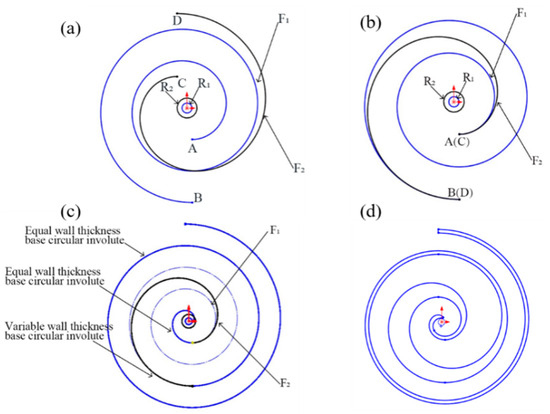
Figure 1.
Forming process of variable diameter double arc combined profile.
After the drawing of the variable diameter dual circular arc combined baseline is completed, the combined baseline is normally offset by a distance of Ror/2 to form the inner and outer walls of the vortex tooth. By copying the inner and outer wall profiles and performing a 180° center symmetrical transformation, the inner wall of the static disc and the outer wall of the dynamic vortex can be obtained. The tooth ends are modified with dual circular arcs, and the complete two-dimensional drawing of the combined vortex tooth profile is shown in Figure 1d.
2.3. Performance Analysis of the Working Chamber
In the meshing area of the dynamic and static vortex teeth of the compressor, there is always a gap to reduce friction and wear between parts [22]. For new volumetric vortex compressors, axial gaps are usually sealed using sealing strips and coatings. Therefore, considering only radial gaps and not axial gaps, the size of the radial gap determines the degree of gas leakage between compression chambers, significantly affecting the compressor’s efficiency and performance. An appropriate control of the vortex disk’s size and gaps during the design and manufacturing stages can optimize the compressor’s performance, hence the introduction of a comparative analysis of important parameters such as radial leakage line length, stroke volume, unit rotation angle, and radial gas leakage amount. However, if the radial gap is too small or nonexistent, the compressor cannot operate smoothly; if it is too large, it causes adverse effects such as gas tangential leakage, chamber air pulsation, and rapid temperature rise. Therefore, important parameters like radial leakage line length, stroke volume, unit rotation angle, and gas radial leakage amount are introduced for comparative analysis.
The general theoretical equation for the radial leakage line length of the combined profile vortex compressor is shown in Equation (5):
where x and y are the equations for the horizontal and vertical coordinates of the baseline.
The general theoretical equation for the stroke volume Vb of the combined profile vortex compressor is shown in Equation (6):
where S(φ) is the cross-sectional area of the suction chamber, l is the corresponding length of the vortex generatrix of the chamber, ζ is the area reduced by the movement of the moving disk.
The theoretical results are shown in Table 2. It can be observed that the stroke volumes of the uniform thickness and combined profile vortex compressors are equal. However, the leakage line length of the optimized new variable diameter dual circular arc combined profile is significantly less than that of the uniform thickness involute profile, with the radial leakage line length being reduced by 25% in comparison. When different working fluids in the chambers sequentially and continuously complete the compression process as the main shaft rotates, the radial engagement points along the leakage line length start from the involute development angle to the starting angle, completing the entire engagement process. It can be inferred that the shorter the leakage line length, the fewer the number of radial engagement points, thus reducing the volumetric loss caused by gas leakage through the radial gap.
Table 2.
Geometric properties related parameters.
The simplified radial clearance leakage model is shown in Figure 2. The radial leakage height is scroll-tooth height H, and the width at the clearance is changing state, that is , dr1, dr2. Assuming that the average value of the radial clearance is dr. The gas flow at the radial gap conforms to the one-dimensional steady flow.
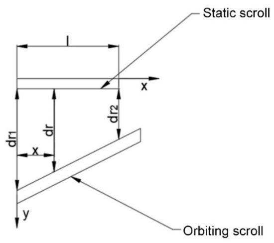
Figure 2.
Simplified model of radial clearance leakage.
The energy equation is shown in Equation (8).
The tangential leakage velocity gas from neighboring compression cavities is shown in Equation (9) as follows.
The tangential gas leakage per unit rotary angle is shown in Equation (10).
where ρi(θ) is the instantaneous density of the gas in the working chamber, w is the rotational speed of the main shaft, ατ is flow coefficient, H is leakage length.
3. Establishment of the Fluid Domain Model
A vortex compressor is a type of fluid machinery that compresses gas by the eccentric rotation and translational motion of a vortex disk, driven by the main shaft, meshing with a static vortex disk [23]. During operation, several closed and symmetrical crescent-shaped volumetric spaces are formed between the dynamic and static vortex disks. As the main shaft rotates, these crescent-shaped volumes continuously move towards the center, thus realizing gas intake, compression, and exhaust. Figure 3 shows the fluid domain model of the combined profile and uniform wall thickness vortex compressor, including symmetrically arranged suction chambers, compression chambers, and exhaust chambers. Here, the involute development angle in the range (0, 2π) corresponds to the exhaust chamber, (2π, 6π) to the compression chamber, and (6π, 8π) to the suction chamber. The basic parameters of the fluid domain model are as listed in Table 3. In this paper, the maximum tip speed of the variable diameter dual circular arc vortex compressor is 21.049 m/s, which is subsonic. Under subsonic conditions, the vortex compressor does not generate shock waves.
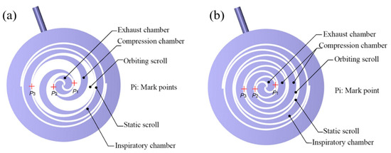
Figure 3.
Fluid domain model of working chamber. (a) Fluid domain of combined profile vortex compressor; (b) fluid domain of uniform wall thickness vortex compressor.
Table 3.
Comparison of basic parameters of vortex compressor.
4. Finite Element Preprocessing
4.1. Structured Grid Division
The dynamic vortex tooth’s base circle center revolves around the static vortex tooth’s base circle center, continuously compressing the fluid in the chamber. Therefore, Computational Fluid Dynamics (CFD) moving grid technology is used for dynamic simulation, where the fluid domain grid is compressed or stretched as the dynamic vortex disk moves, and the gap between dynamic and static vortex teeth is only a few tens of micrometers [24]. Thus, selecting the appropriate grid type for dividing the fluid domain of the compression chamber is significant for improving computational accuracy and efficiency.
This paper, based on CFD software, utilizes an automated right-angle Cartesian grid generator for setting related parameters, completing the division of the working chamber’s fluid domain grid, and ensuring the boundary fitting of the area to guarantee the accuracy and reliability of the simulation results. Since the inlet and outlet boundary conditions do not move during the solution process, and the grid quality requirement is not high, only the inlet and outlet fluid domains are divided to improve the efficiency of the solution. The overall grid division of the combined profile and uniform wall thickness three-dimensional fluid domain model is shown in Figure 4.
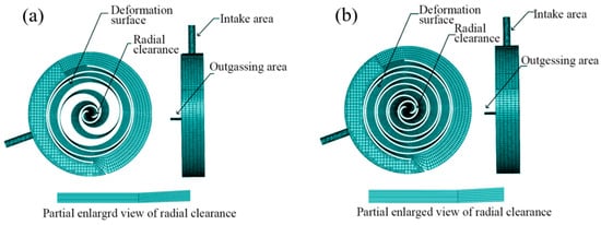
Figure 4.
Working cavity fluid domain grid. (a) Fluid domain grid of combined profile vortex compressor; (b) fluid domain grid of uniform wall thickness vortex compressor.
4.2. Boundary Conditions
This paper assumes that the gas inside the working chamber of the vortex compressor behaves as an ideal gas. Vortex compressors have a complex structure, and the gas flow during operation generates vortices. To achieve higher credibility and accuracy in a wide range of flows, the RNG k-ε turbulence model is chosen. Considering the temperature changes in the gas during compression, the energy equation is enabled. With high-speed and high-pressure gas flow in the chamber and a finely resolved grid, a high-accuracy, fast-converging coupled solver is chosen. The fluid domain model of the vortex compressor is complex, and to quickly meet convergence criteria, coupled initialization is used, applying different solution methods for initial value assignment.
The solution equations for the RNG k-ε turbulence model are as follows:
where k is the turbulent kinetic energy, σk is the turbulent energy prandtl number, valued at 1, ε is the turbulence dissipation rate, σε is turbulence dissipation rate prandtl number, valued at 1.3, ν’ is turbulence fluctuation velocity, S’ij is the stress strain, μt is the turbulent viscosity, Gt is the turbulent kinetic energy (k) production term, C2(RNG)is the correction coefficient.
4.3. Grid Sensitivity Test
The crux of grid sensitivity testing lies in the relationship between grid density and accuracy. Theoretically, a finer grid results in higher accuracy of the solution. This is because smaller grids can better approximate complex geometries and capture local physical phenomena [25]. However, considering computational costs, as the number of grids increases, so does the computational time. Moreover, beyond a certain level of refinement, the incremental accuracy becomes less pronounced. Thus, a balance between the number of grids and accuracy is necessary. In finite element analysis, finding a suitable equilibrium between computational scale (number of grids) and accuracy is crucial. This often involves minimizing computational resources while ensuring result reliability. Figure 5 shows the trend of exhaust mass flow and radial gap layers as a function of grid quantity, indicating that changes in exhaust mass flow with an increase in grid count are minimal with a standard deviation of 8.5 × 10−05, suggesting low variability. Therefore, the number of grids has a minor impact on simulation outcomes, with 61,207 grids being closest to the dataset’s average, suggesting that selecting seven layers of radial gaps in the working chamber’s fluid domain for numerical simulation is most cost-effective and reliable.
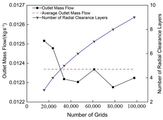
Figure 5.
Grid sensitivity test.
5. Simulation Results and Analysis
5.1. Pressure Field
Figure 6 shows the variation in pressure at a fixed detection point at the radial gap at the starting position, as the main shaft completes one cycle. The pressure exhibits a decreasing gradient change when approaching the radial gap, consistent with the cloud diagram. However, as the main shaft rotates, the pressure at the radial gap engagement points increases as the second compression chamber shifts towards the center. The pressures at symmetric radial gap engagement points are equal, with a significant pressure difference at adjacent engagement points. The pressure at the engagement points of the combined profile vortex compressor is higher than that of the uniform wall thickness vortex compressor. As the pressure difference between adjacent compression chambers increases, tangential leakage caused by the radial gap intensifies, but this does not significantly affect the distribution of the pressure field in the working chamber. Therefore, the pressure distribution is basically uniform in the same compression chamber both radially and axially.
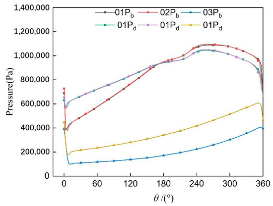
Figure 6.
Mark point pressure curve.
The pressure distribution in the same compression chamber is basically uniform both radially and axially.
Figure 7 shows the pressure field cloud distribution at different rotational angles after the working fluid in the working chamber stabilizes. For both the combined profile and uniform wall thickness vortex compressors, the pressure increases from the suction chamber to the central exhaust chamber and is symmetrically distributed around the center, conforming to the theoretical cycle pressure variation. The pressure in the central exhaust chamber slightly decreases when reaching the exhaust angle due to the outward exhaust, with a clear pressure difference between adjacent compression chambers. The pressure distribution within the same compression chamber is uniform in both radial and axial directions. The maximum pressure in the working chamber of both the combined profile and uniform wall thickness vortex compressors increases and then decreases as the main shaft rotates, with the optimized combined profile working chamber having a higher flow pressure compared to the uniform wall thickness vortex compressor.
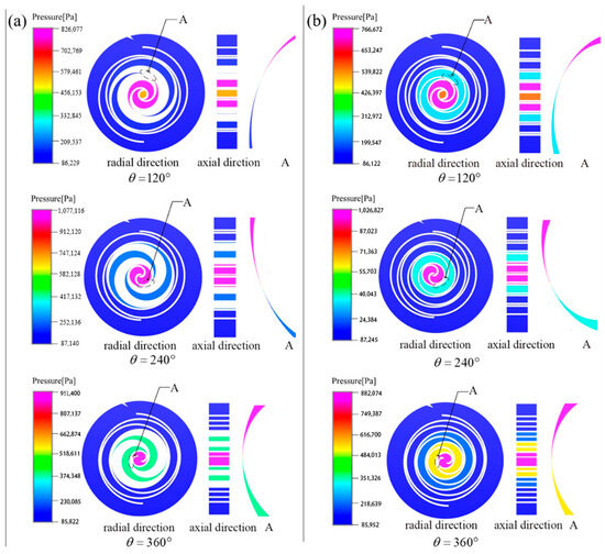
Figure 7.
Pressure could map distribution at different corners. (a) Pressure nephogram of combined profile; (b) pressure nephogram of uniform wall thickness profile.
Figure 7a shows an enlarged view of the radial engagement gap area between the dynamic and static vortex teeth. The radial gap of the vortex compressor acts as a channel that is narrow in the middle and wider on both sides. As the eccentric main shaft performs rotary translational motion, the engagement points of the dynamic and static vortex teeth continuously move towards the central chamber. Simultaneously, the pressure difference on both sides of the engagement point gradually increases, showing a decreasing gradient change in pressure from the high-pressure chamber to the low-pressure chamber at the radial gap engagement point.
Leakage in the working chamber of vortex compressors leading to unstable pressure fluctuations further affects the smooth operation and performance stability of the compressor. Figure 8 shows the trend of the total pressure at the inlet and outlet as the main shaft angle changes during five cycles of operation of the vortex compressor. The total pressure at the outlet of both the combined profile and uniform wall thickness vortex compressors shows periodic changes during the second cycle of the main shaft’s rotation, with the trend gradually stabilizing. When the main shaft angle approaches 290°, the flow cross-sectional area of the exhaust port is at its maximum, and the total pressure at the outlet reaches its maximum value. The maximum total pressure at the outlet of the combined profile vortex compressor is 4.34% higher than that of the uniform wall thickness vortex compressor, and the average total pressure is 2.38% higher. The average total pressures at the inlet of both the combined profile and uniform wall thickness vortex compressors are almost equal and stabilize at 107,380 Mpa. A comparison of the related pressure values is shown in Table 4. Compared to the uniform wall thickness vortex compressor, the maximum outlet pressure of the combined profile vortex compressor is increased by 4.34%, and the average total outlet pressure is increased by 2.38%. Additionally, the total outlet pressure of the variable diameter vortex compressor is always higher than the outlet pressure, indicating the absence of backflow at the exhaust port, thereby reducing leakage losses during operation of the compressor.
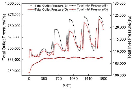
Figure 8.
Comparison of inlet and outlet pressure.
Table 4.
Pressure comparison value of different profile.
Figure 9 shows the trend of mass flow rate at the inlet and outlet over five cycles of the main shaft’s operation in the vortex compressor. The mass flow rates at the inlet and outlet exhibit regular changes during the second cycle of operation. As the total pressure at the outlet reaches its maximum value, the mass flow rate at the outlet also reaches its peak. The maximum mass flow rate at the outlet of the combined profile is 4.4% higher than that of the uniform wall thickness profile. During the operation of the vortex compressor, the processes of suction, compression, and exhaust occur simultaneously. Under the condition of equal suction chamber volume in both the combined profile and uniform wall thickness vortex compressors, the length of the leakage line in the uniform wall thickness involute profile is 25% longer than that in the optimized new variable diameter dual circular arc combined profile, intensifying tangential leakage during operation. Therefore, the average mass flow rate at the outlet of the combined profile is 0.74% higher than that of the uniform wall thickness profile. Additionally, since the working fluid in the vortex compressor is transient compressible flow, the mass flow rates at the inlet and outlet are not equal.
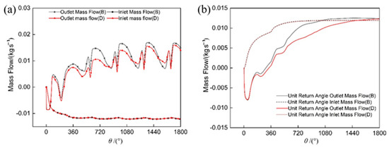
Figure 9.
Mass flow comparison. (a) Comparison of inlet and outlet mass flow; (b) comparison of mass flow per unit return angle.
After the vortex compressor stabilizes in operation, the mass flow rates at the inlet and outlet per unit rotation angle are not equal. This is mainly due to tangential leakage caused by the radial gap and the compression of the working fluid in the working chamber by the vortex teeth, which causes abrupt changes in speed and direction, resulting in vortices of different sizes. The combined profile vortex compressor has fewer radial engagement points at any given moment compared to the uniform wall thickness vortex compressor, hence reducing the gas leakage per unit rotation angle by 3.2%. Specific comparative parameters of mass flow rates for both the combined profile and uniform wall thickness vortex compressors are shown in Table 5. The greater the leakage, the less the amount of gas involved in the actual work of the scroll compressor, and the lower the volumetric efficiency of the compressor.
Table 5.
Comparison of mass flow values of different profiles.
5.2. Temperature Field
Figure 10a shows the variation in temperature at a fixed detection point at the radial gap over one cycle of the main shaft’s movement. As the main shaft rotates, when the radial engagement point approaches the monitoring point, the temperature at the radial gap shows a decreasing gradient, transitioning from a high temperature zone above to a lower temperature zone below. However, due to the pressure difference between adjacent working chambers causing tangential leakage, the gas in the high-pressure chamber flows into the low-pressure chamber, leading to temperature fluctuations at the engagement points. Moreover, the temperatures at symmetric engagement points are not equal, with the combined profile showing greater unevenness in temperature at symmetric engagement points, and a more noticeable temperature difference between adjacent compression chambers.
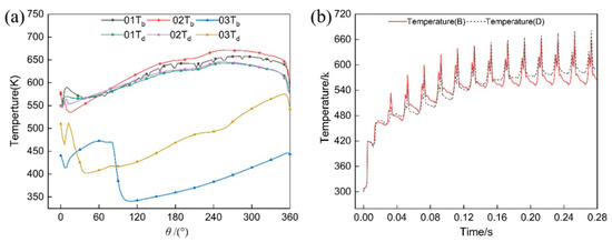
Figure 10.
Temperature contrast chart. (a) Temperature curve of marking point; (b) outlet temperature.
As shown in Figure 10b, the exhaust temperature exhibits periodic changes as the main shaft rotates. Within a single cycle, the exhaust temperature gradually increases and tends to stabilize. The combined profile vortex compressor reaches thermal equilibrium with the external environment in the 6-th cycle, with an average temperature tending towards 577 K. Meanwhile, the uniform wall thickness vortex compressor shows periodic changes in outlet temperature after 12 cycles, with an average temperature approaching 600 K. After the vortex compressor stabilizes in operation, at any angle of the main shaft rotation, the outlet temperature of the uniform wall thickness vortex compressor is slightly higher than that of the combined profile vortex compressor. Uniform thickness vortex compressors need to consume more energy to compensate for efficiency losses caused by thermal leakage, directly leading to a decrease in the overall efficiency of vortex compressors.
Figure 11 shows the distribution of temperature field cloud maps at different rotational angles after the working fluid in the working chamber stabilizes. It can be seen that the temperature gradually increases from the suction chamber to the central compression chamber. Due to tangential leakage caused by the radial gap, the temperature distribution within a single working chamber is uneven both radially and axially. Furthermore, since the exhaust area is not located at the center of the working chamber, the temperature distribution in the symmetric compression chambers is also uneven. As the dynamic vortex disk moves with the main shaft, the gas in each chamber continuously moves towards the center. The pressure difference between adjacent compression chambers increases, leading to more severe tangential leakage closer to the central chamber, which results in a more pronounced uneven distribution within the chamber. The gas brought by the leakage flow might have been compressed and heated upstream, causing a local temperature increase when mixed with the gas in the low-pressure chamber.
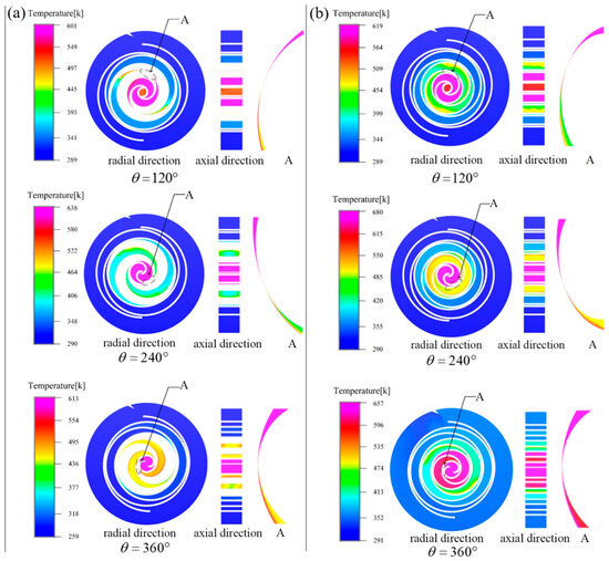
Figure 11.
Temperature nephogram distribution at different corner positions. (a) Temperature nephogram of combined profile; (b) temperature nephogram of constant wall thickness profile.
5.3. Velocity Field
Figure 12 shows the distribution of velocity vector diagrams at different rotational angles after the working fluid in the working chamber stabilizes. It can be observed that in the various working chambers of the vortex compressor, the flow of the working fluid is smooth, with a flow rate slightly higher than that in the back pressure chamber. During operation, vortex compressors experience pressure differences, and the speed of the gas brought by tangential leakage flow might exceed the surrounding gas speed, leading to an uneven distribution in the velocity vector field. Tangential leakage occurs at the radial gap between the dynamic and static vortex teeth, where the velocity reaches its peak. The maximum velocity in the combined profile vortex compressor is 570 m/s, while in the uniform wall thickness vortex compressor, it is 492 m/s. The higher maximum leakage velocity in the combined profile is due to the larger pressure difference between adjacent compression chambers in this design. Vortices appear near the back pressure chamber in the intake area and at the radial gaps between adjacent compression chambers, caused by abrupt changes in the velocity and direction of the working fluid. The areas where vortices occur also exhibit localized high temperatures, making vortices one of the causes of uneven temperature distribution in the compression chamber.
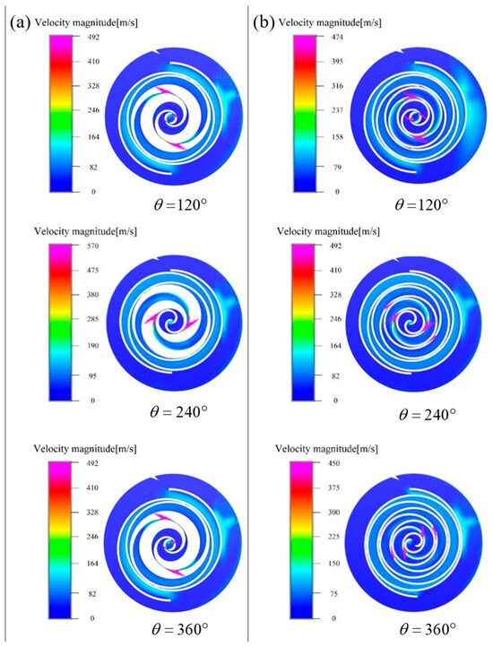
Figure 12.
Distribution of velocity vector diagram at different corner positions. (a) Velocity vector diagram of combined profile; (b) velocity vector diagram of uniform wall thickness.
6. Conclusions
(1) Based on the involute theory equation, the theoretical equation of the variable diameter dual circular arc vortex profile is determined by comparing the drawing process of the new variable diameter dual circular arc combined profile.
(2) By introducing the uniform wall thickness involute profile, a geometric performance calculation model for vortex compressors is established. It is found that the stroke volumes of the combined profile and uniform wall thickness vortex compressors are equal, but the leakage line length of the vortex teeth in the combined profile is 25% less than that in the uniform wall thickness profile. Additionally, a simplified tangential leakage calculation model per unit rotation angle for vortex compressors is established.
(3) Using CFD moving grid technology, the transient distribution of various state fields in the working chamber of the vortex compressor is simulated. The study finds that gas pressure and temperature show an increasing trend from the suction chamber to the central exhaust chamber, with a decreasing gradient change in pressure and temperature at the radial gap. The tangential leakage caused by the radial gap has a small impact on the pressure field but causes significant local unevenness in the temperature field in both axial and radial directions. The working fluid velocity reaches its peak at the radial gap. The maximum total pressure at the outlet of the combined profile vortex compressor is 4.34% higher than that of the uniform wall thickness, and the average total pressure is increased by 2.38%, with a 3.2% reduction in leakage. The limitations in future research on vortex compressors primarily revolve around the complexity of profile design, inadequacy in simulating the compression process, and restrictions in calculating leakage quantities. Future studies will likely optimize the profiles of vortex compressors through mathematical modeling and computer simulation, establishing more accurate models of the compression process to better simulate compressor performance under different operational conditions.
Author Contributions
Conceptualization, L.H. and Y.W.; methodology, L.H. and C.Q.; software, L.H. and M.W.; validation, L.H., S.R. and C.M.; formal analysis, C.Q.; investigation, Y.W.; resources, L.H.; data curation, L.H.; writing—original draft preparation, L.H. and C.Q.; writing—review and editing, C.Q. and C.M.; visualization, S.R. and M.W.; supervision, L.H. and C.Q.; project administration, L.H. and Y.W.; funding acquisition, L.H. All authors have read and agreed to the published version of the manuscript.
Funding
This research was funded by Provincial Key Research Project of Natural Sciences in Universities of Anhui Province, grant number KJ2020A0489.
Institutional Review Board Statement
Not applicable.
Informed Consent Statement
Not applicable.
Data Availability Statement
The original contributions presented in the study are included in the article, further inquiries can be directed to the corresponding author.
Conflicts of Interest
Author Yu Wang was employed by the company Guoqi Pujin Intelligent Technology Co., Ltd. The remaining authors declare that the research was conducted in the absence of any commercial or financial relationships that could be construed as a potential conflict of interest.
References
- Emhardt, S.; Tian, G.; Song, P.; Chew, J.; Wei, M. CFD analysis of the influence of variable wall thickness on the aerodynamic performance of small-scale ORC scroll expanders. Energy 2022, 244, 122586. [Google Scholar] [CrossRef]
- Zhu, Y.; Yuan, W.; Guo, Q.; Wang, W.; Zhang, L.; Zhu, S. Kinematic Characteristics Analysis of Orbiting Scroll and Structural Optimization of Oldham’s Coupling in Scroll Compression. Machines 2022, 10, 623. [Google Scholar] [CrossRef]
- Cardone, M.; Gargiulo, B. Numerical simulation and experimental validation of an oil free scroll compressor. Energies 2020, 13, 5863. [Google Scholar] [CrossRef]
- Zhang, X.; Zhang, B.; Cao, J.; Su, L.; Li, K. Numerical investigation on the performance and vapor injection process of a scroll compressor with different injection features. Appl. Therm. Eng. 2022, 217, 119061. [Google Scholar] [CrossRef]
- Peng, B.; Liu, H.; Zhang, P.; Tao, Y.; Qi, T. Construction and Analysis of Variable Wall Thickness Profile of Double Scroll Teeth of Scroll Compressor. E3S Web Conf. 2021, 267, 02062. [Google Scholar] [CrossRef]
- Cheng, S.; Feng, Y.; Wang, K.; Meng, X. Tribo-dynamics modeling and analysis of key friction pairs in scroll compressor with floating fixed scroll design. Eng. Appl. Comput. Fluid Mech. 2022, 16, 2270–2285. [Google Scholar] [CrossRef]
- Pereira, E.L.; Deschamps, C.J. Numerical analysis and correlations for radial and tangential leakage of gas in scroll compressors. Int. J. Refrig. 2020, 110, 239–247. [Google Scholar] [CrossRef]
- Yu, Y.; Wang, X.M. Transient flow analysis for multi-state automotive scroll compressors. J. Phys. Conf. Ser. 2020, 1601, 042006. [Google Scholar] [CrossRef]
- Wei, M.; Song, P.; Zhao, B.; Shi, L.; Wang, Z.; Ma, C. Unsteady flow in the suction process of a scroll expander for an ORC waste heat recovery system. Appl. Therm. Eng. 2015, 78, 460–470. [Google Scholar] [CrossRef]
- Cui, M.M. Numerical Study of Unsteady Flows in a Scroll Compressor. J. Fluids Eng. 2006, 128, 947–955. [Google Scholar] [CrossRef]
- Li, H.-S.; Wu, K.-B.; Wang, J.-S.; Chen, Y.-H.; Wu, T. Finite Element Analysis of Oil-free Scroll Compressor Seal Element. Fluid Mach. 2015, 43, 19–23. [Google Scholar]
- Sung, J.P.; Boo, J.H.; Jung, E.G. Transient Thermodynamic Modeling of a Scroll Compressor Using R22 Refrigerant. Energies 2020, 13, 3911. [Google Scholar] [CrossRef]
- Wang, B.; Li, X.; Shi, W. A general geometrical model of scroll compressors based on discretional initial angles of involute. Int. J. Refrig. 2005, 28, 958–966. [Google Scholar] [CrossRef]
- Stevanovic, V.D.; Petrovic, M.M.; Cucuz, S.; Milivojevic, S.; Ilic, M. Numerical Prediction of Refrigerant Oil Two-Phase Flow from Scroll Compressor Discharge to the Suction Side via Back Pressure Chamber. Processes 2023, 12, 6. [Google Scholar] [CrossRef]
- Li, X.; Wu, W.; Zhang, J.; Guo, C.; Ke, F.; Jiang, F. Analysis of 3D Transient Flow in a High-Speed Scroll Refrigeration Compressor. Energies 2023, 16, 3089. [Google Scholar] [CrossRef]
- Fang, J.; Xu, Y.; Zhang, H.; Yang, Z.; Wan, J.; Liu, Z. Experimental Research on the Output Performance of Scroll Compressor for Micro Scale Compressed Air Energy Storage System. Sustainability 2023, 15, 15665. [Google Scholar] [CrossRef]
- Wang, C.; Zhang, S.; Lei, B.; Cheng, J.; Wu, J. Analysis on influence factors of back pressure in an asymmetrical algebraic scroll compressor. Int. J. Refrig. 2022, 138, 97–107. [Google Scholar] [CrossRef]
- Wang, L.C.; Chen, J.; Zhao, Y.Y.; Hussain, S.H. Research on the natural meshing mechanism and testing analysis of scroll profiles for refrigeration scroll compressor. Sci. China Technol. Sci. 2010, 53, 2783–2791. [Google Scholar] [CrossRef]
- Ma, X.; Zhang, C.; Li, K. Hybrid Modeling and Efficiency Analysis of the Scroll Compressor Used in Micro Compressed Air Energy Storage System. Appl. Therm. Eng. 2019, 161, 114139. [Google Scholar] [CrossRef]
- Zheng, S.; Wei, M.; Song, P.; Hu, C.; Tian, R. Thermodynamics and flow unsteadiness analysis of trans-critical CO2 in a scroll compressor for mobile heat pump air-conditioning system. Appl. Therm. Eng. 2020, 175, 115368. [Google Scholar] [CrossRef]
- Du, Y.; Pekris, M.; Tian, G. CFD analysis of flank clearance sizes on micro-scale transcritical CO2 scroll expander. Appl. Therm. Eng. 2023, 232, 120980. [Google Scholar] [CrossRef]
- Rak, J.; Pietrowicz, S. Internal flow field and heat transfer investigation inside the working chamber of a scroll compressor. Energy 2020, 202, 117700. [Google Scholar] [CrossRef]
- Cavazzini, G.; Giacomel, F.; Benato, A.; Nascimben, F.; Ardizzon, G. Analysis of the inner fluid-dynamics of scroll compressors and comparison between CFD numerical and modelling approaches. Energies 2021, 14, 1158. [Google Scholar] [CrossRef]
- Liu, Z.; Li, Z.; Xie, D.; Wu, H. Unsteady characteristic and flow mechanism of a scroll compressor in small-scale compressed air energy storage system. J. Energy Storage 2022, 51, 104368. [Google Scholar] [CrossRef]
- Song, P.; Wu, D.; Lu, Z.; Zheng, S.; Wei, M.; Zhuge, W.; Zhang, Y. An Improved Geometric Theoretical Model and Throughflow Prediction Method for a CO2 Scroll Compressor of Automotive Air Conditioning System. Int. J. Energy Res. 2023, 2023, 9382690. [Google Scholar] [CrossRef]
Disclaimer/Publisher’s Note: The statements, opinions and data contained in all publications are solely those of the individual author(s) and contributor(s) and not of MDPI and/or the editor(s). MDPI and/or the editor(s) disclaim responsibility for any injury to people or property resulting from any ideas, methods, instructions or products referred to in the content. |
© 2024 by the authors. Licensee MDPI, Basel, Switzerland. This article is an open access article distributed under the terms and conditions of the Creative Commons Attribution (CC BY) license (https://creativecommons.org/licenses/by/4.0/).