
Commissioning of Bunch Compressor to Compress Space Charge-Dominated Electron Beams for THz Applications
 , ,
, ,
Abstract
1. Introduction
2. Commissioning Goal
3. Background
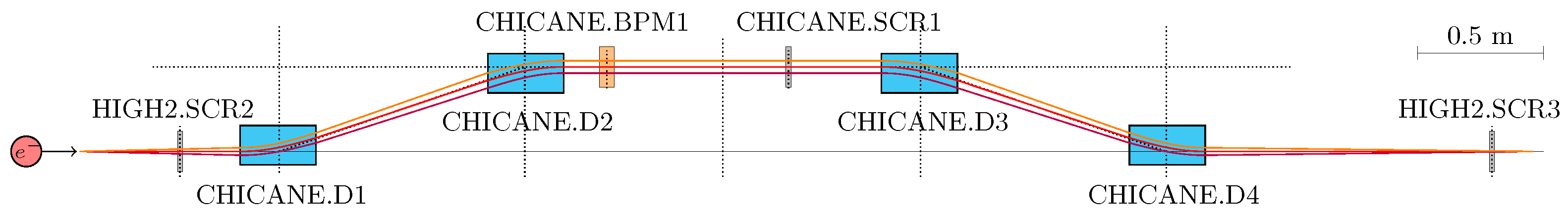
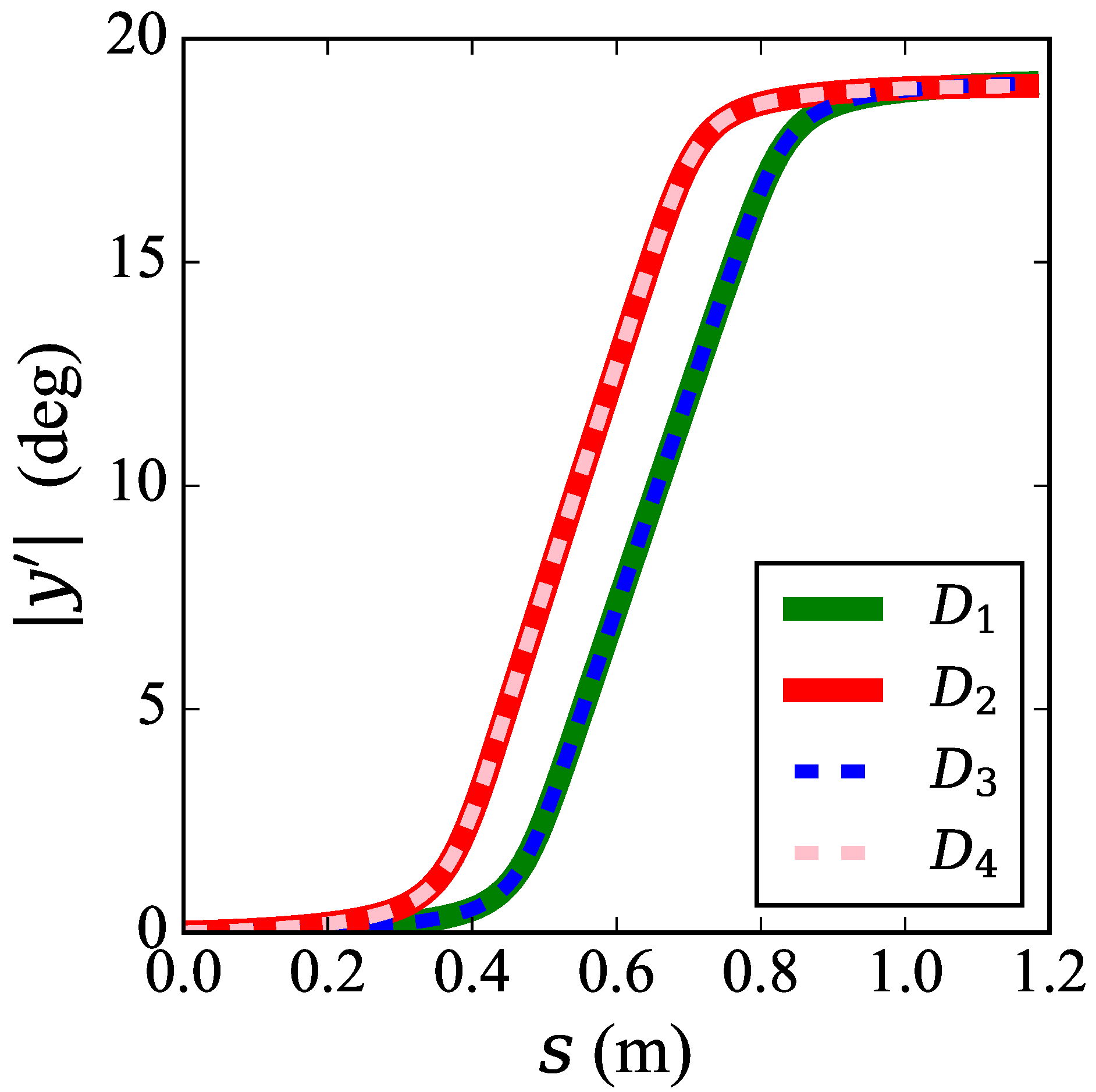
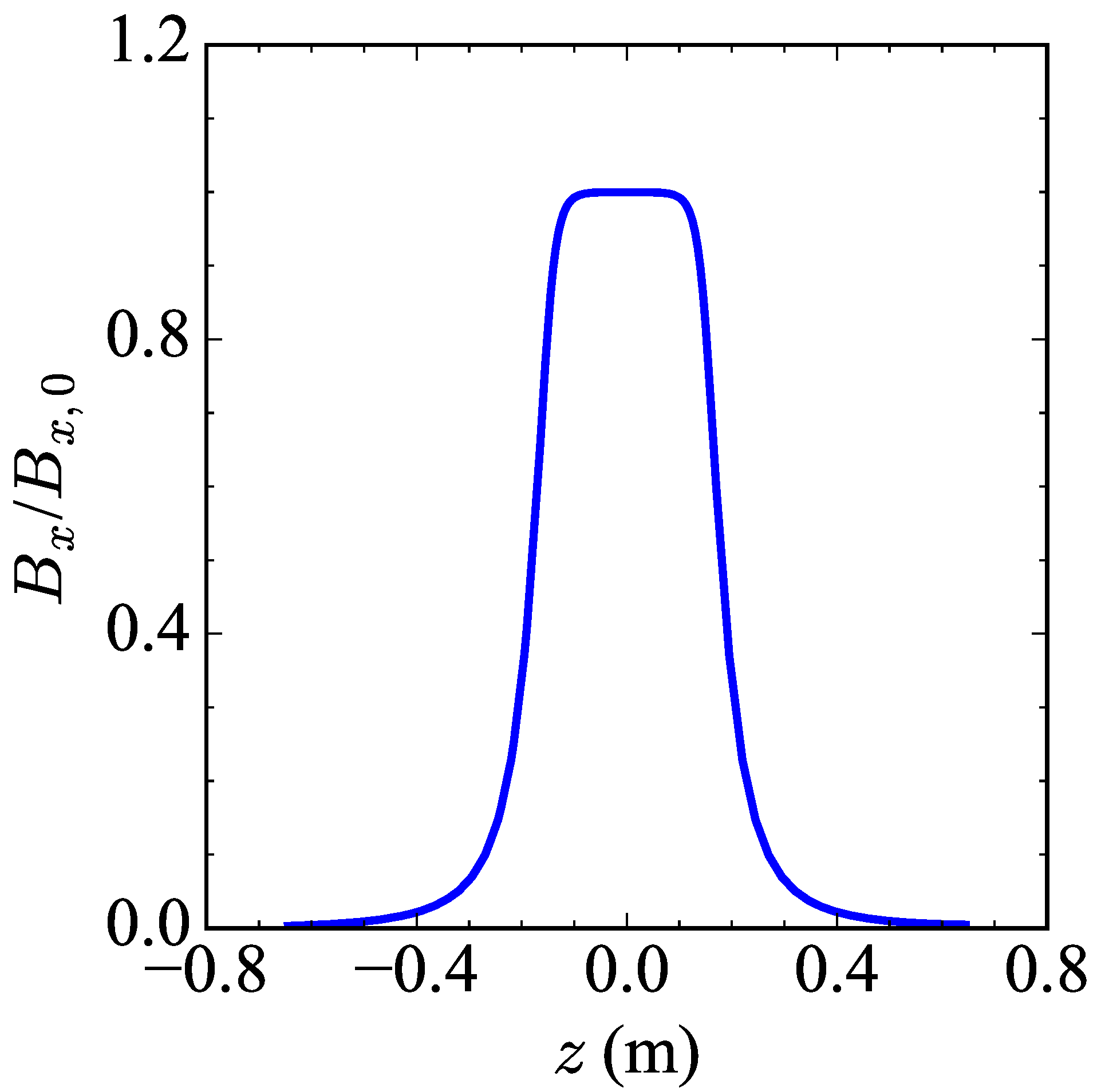
4. Dipole Magnet Current Constraints
5. Chicane Commissioning
5.1. Procedures
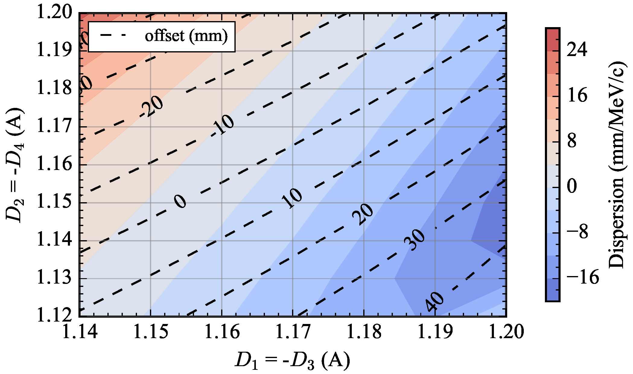
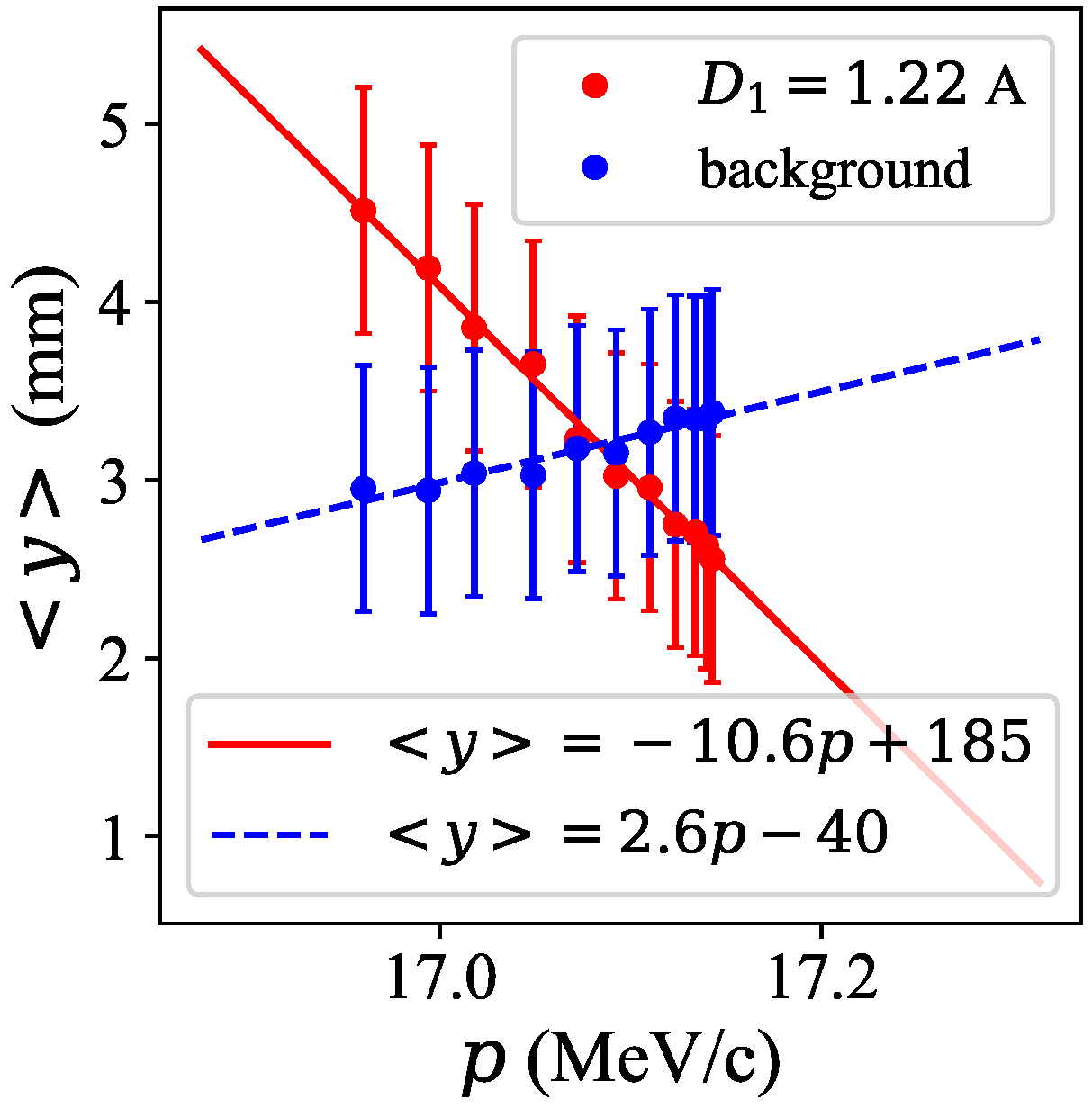
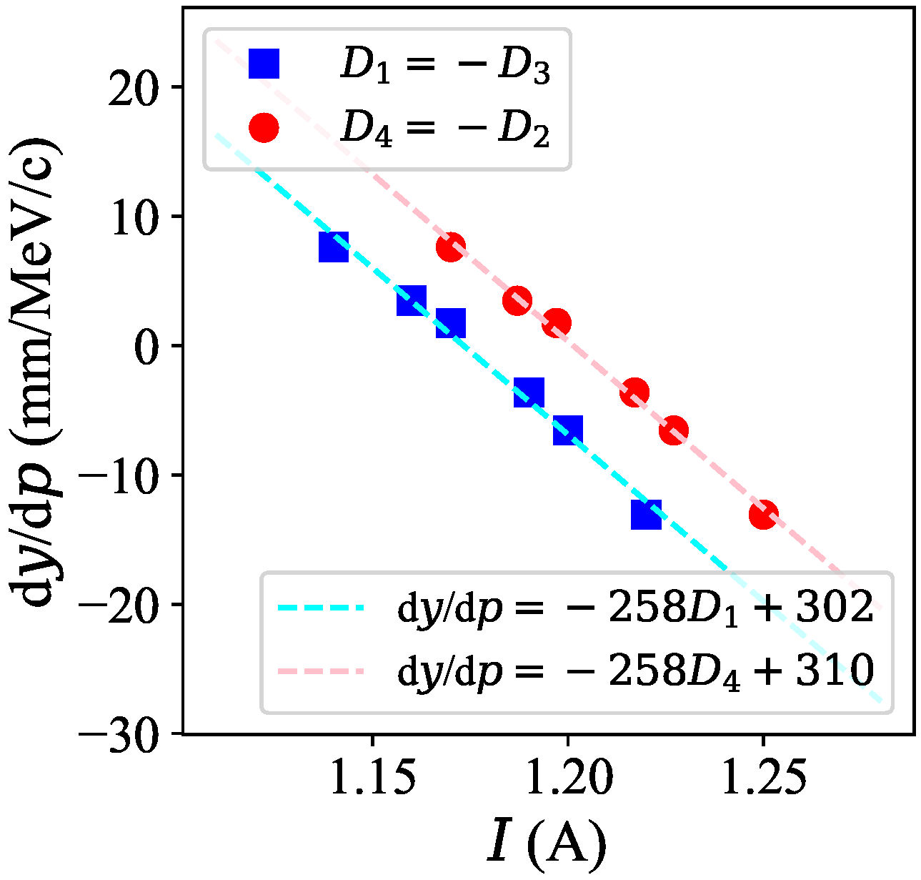
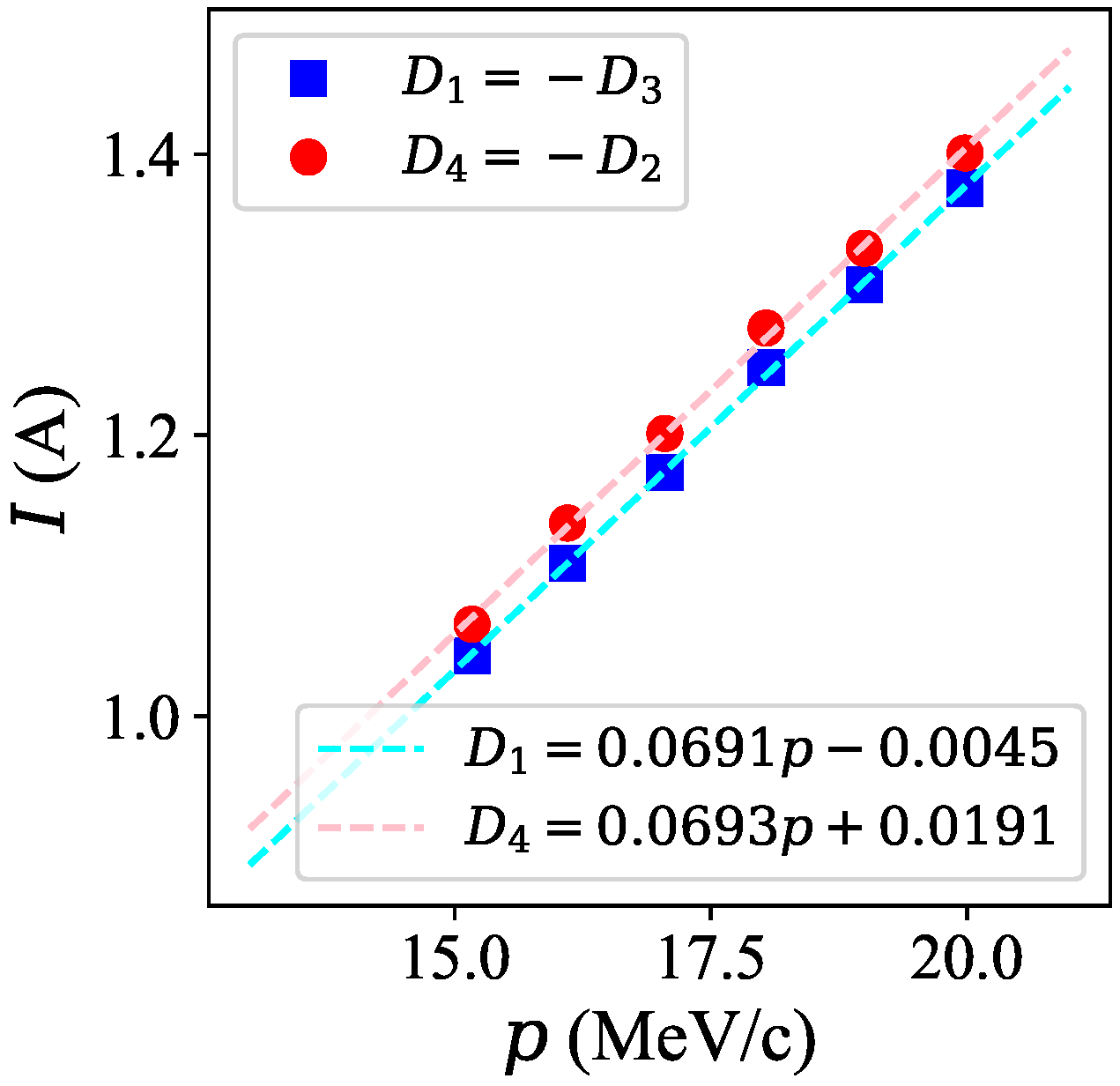
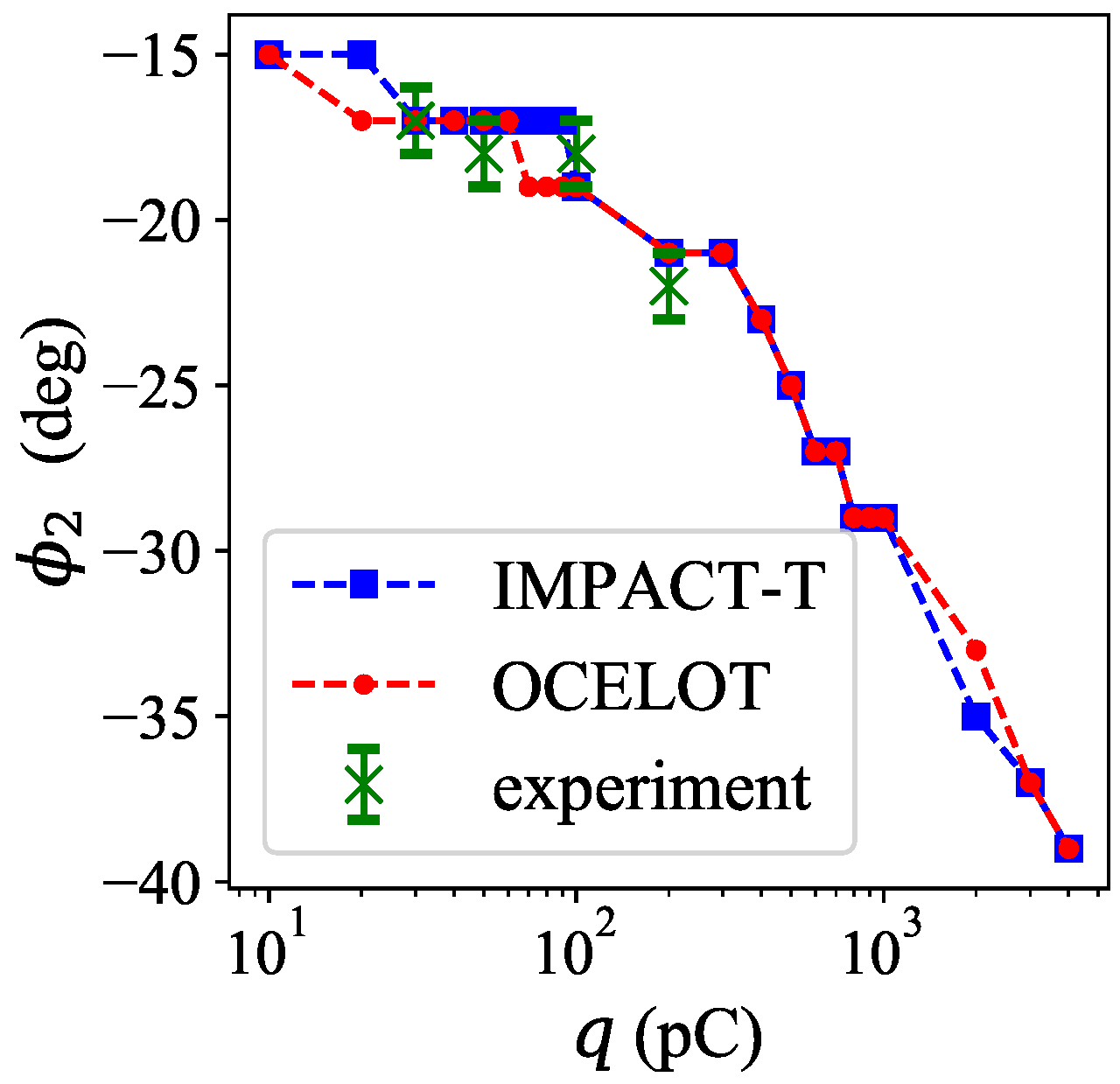
5.2. Data Analysis
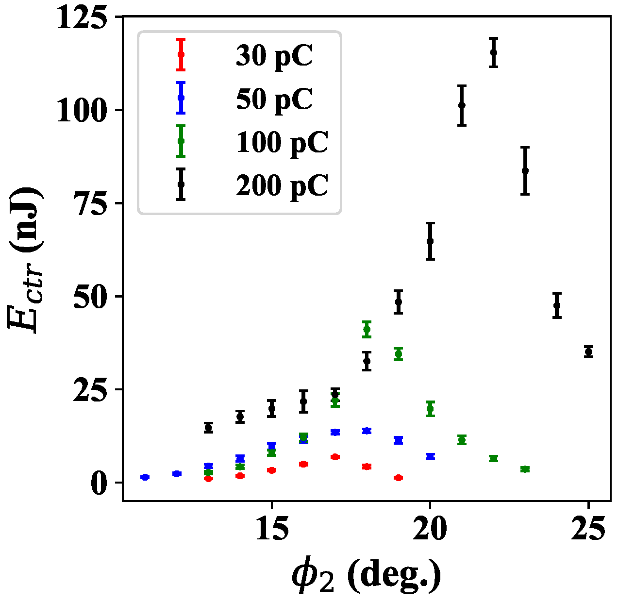
5.3. CTR Measurement
6. Summary
7. Future Plans
Author Contributions
Funding
Institutional Review Board Statement
Informed Consent Statement
Data Availability Statement
Acknowledgments
Conflicts of Interest
References
- Asova, G.; Bahr, J.; Boulware, C.H.; Donat, A.; Gensch, U.; Grabosch, H.J.; Hakobyan, L.; Hanel, M.; Henschel, H.; Ivanisenko, Y.; et al. Status of the Photo Injector Test Facility at DESY, Zeuthen Site (PITZ). In Proceedings of the IPAC’10, Kyoto, Japan, 23–28 May 2010; paper TUPE010. pp. 2164–2166. [Google Scholar]
- Lueangaramwong, A.; Li, X.; Boonpornprasert, P.; Lishilin, O.; Krasilnikov, M.; Aboulbanine, Z.; Adhikari, G.; Aftab, N.; Chaisueb, N.; Georgiev, G.; et al. Numerical Study of Beam Dynamics in PITZ Bunch Compressor. In Proceedings of the 12th International Particle Accelerator Conference (IPAC’21), Campinas, Brazil, 24–28 May 2021. paper WEPAB274. [Google Scholar]
- Voss, G.A. Status of the HERA Project. Conf. Proc. C 1983, 830811, 29–31. [Google Scholar] [CrossRef]
- Systèmes, D. Electromagnetic Simulation Solvers—CST Studio Suite. Available online: https://www.3ds.com/products-services/simulia/products/cst-studiosuite/solvers/ (accessed on 7 May 2022).
- Derbenev, Y.S.; Saldin, E.L.; Shiltsev, V.D.; Rossbach, J. Microbunch Radiative Tail-Head Interaction; Technical Report No. DESY-TESLA-FEL-95-05; DESY: Hamburg, Germany, 1995. [Google Scholar]
- Khan, D.Z.; Raubenheimer, T.O. Approximated expressions for the coherent synchrotron radiation effect in various accelerator scenarios. Phys. Rev. Accel. Beams 2021, 24, 080701. [Google Scholar] [CrossRef]
- Conti, M.R.; Bacci, A.; Giove, D.; Petrillo, V.; Samsam, S.; Sertore, D.; Serafini, L. New approach to space charge dominated beamline design. Phys. Rev. Accel. Beams 2023, 26, 094201. [Google Scholar] [CrossRef]
- Litvinenko, V.N.; Hajima, R.; Kayran, D. Merger designs for ERLs. Nucl. Instrum. Methods Phys. Res. A 2006, 557, 165–175. [Google Scholar] [CrossRef]
- Flöttmann, K. ASTRA: A Space Charge Algorithm, User’s Manual. Available online: https://www.desy.de/~mpyflo/Astra_manual/Astra-Manual_V3.2.pdf (accessed on 1 October 2019).
- Lueangaramwong, A.; Chaisueb, N.; Lishilin, O.; Li, X.; Boonpornprasert, P.; Krasilnikov, M.; Aboulbanine, Z.; Adhikari, G.; Aftab, N.; Georgiev, G.; et al. Longitudinal Phase Space Benchmarking for PITZ Bunch Compressor. In Proceedings of the IPAC’22, Bangkok, Thailand, 12–17 June 2022; pp. 310–312. [Google Scholar]
- Malyutin, D. Time Resolved Transverse and Longitudinal Phase Space Measurements at the High Brightness Photo Injector PITZ. Ph.D. Thesis, University of Hamburg, Hamburg, Germany, 2014. [Google Scholar]
- Qiang, J.; Lidia, S.; Ryne, R.D.; Limborg-Deprey, C. Three-dimensional quasistatic model for high brightness beam dynamics simulation. Phys. Rev. ST Accel. Beams 2006, 9, 044204. [Google Scholar] [CrossRef]
- Agapov, I.; Geloni, G.; Tomin, S.; Zagorodnov, I. OCELOT: A software framework for synchrotron light source and FEL studies. Nucl. Instr. Meth. A 2014, 768, 151–156. [Google Scholar] [CrossRef]
- Tomin, S.; Agapov, I.; Dohlus, M.; Zagorodnov, I. OCELOT as a Framework for Beam Dynamics Simulations of X-Ray Sources. In Proceedings of the IPAC’17, Copenhagen, Denmark, 14–19 May 2017; paper WEPAB031. pp. 2642–2645. [Google Scholar]
- Qiang, J.; Mitchell, C.E.; Ryne, R.D. A fast high-order method to calculate wakefields in an electron beam. Nucl. Instrum. Methods Phys. Res. A 2012, 682, 49–53. [Google Scholar] [CrossRef]
- Mitchell, C.E.; Qiang, J.; Ryne, R.D. A fast method for computing 1-D wakefields due to coherent synchrotron radiation. Nucl. Instrum. Methods Phys. Res. A 2013, 715, 119–125. [Google Scholar] [CrossRef]
- SLT Sensor-und Lasertechnik GmbH, “THz-Detectors”. Available online: https://www.pyrosensor.de/SLT2023-pdf-1217897.pdf (accessed on 8 February 2024).


| (deg.) | (deg.) | (deg.) | (deg.) | Energy Dispersion (mm) |
|---|---|---|---|---|
| 0 | 0 | 0 | 0 | 0 |
| 0.5 | 0 | 0 | 0 | 40.0 |
| 0 | 0.5 | 0 | 0 | −49.3 |
| 0.5 | 0 | 0.5 | 0 | 23.1 |
| −0.5 | 0 | −0.5 | 0 | −22.9 |
| 0 | 0.5 | 0 | 0.5 | −23.1 |
Disclaimer/Publisher’s Note: The statements, opinions and data contained in all publications are solely those of the individual author(s) and contributor(s) and not of MDPI and/or the editor(s). MDPI and/or the editor(s) disclaim responsibility for any injury to people or property resulting from any ideas, methods, instructions or products referred to in the content. |
© 2024 by the authors. Licensee MDPI, Basel, Switzerland. This article is an open access article distributed under the terms and conditions of the Creative Commons Attribution (CC BY) license (https://creativecommons.org/licenses/by/4.0/).
Share and Cite
Lueangaramwong, A.; Kongmon, E.; Li, X.; Boonpornprasert, P.; Georgiev, G.; Krasilnikov, M.; Aboulbanine, Z.; Adhikari, G.; Aftab, N.; Gross, M.; et al. Commissioning of Bunch Compressor to Compress Space Charge-Dominated Electron Beams for THz Applications. Appl. Sci. 2024, 14, 1982. https://doi.org/10.3390/app14051982
Lueangaramwong A, Kongmon E, Li X, Boonpornprasert P, Georgiev G, Krasilnikov M, Aboulbanine Z, Adhikari G, Aftab N, Gross M, et al. Commissioning of Bunch Compressor to Compress Space Charge-Dominated Electron Beams for THz Applications. Applied Sciences. 2024; 14(5):1982. https://doi.org/10.3390/app14051982
Chicago/Turabian StyleLueangaramwong, Anusorn, Ekkachai Kongmon, Xiangkun Li, Prach Boonpornprasert, Georgi Georgiev, Mikhail Krasilnikov, Zakaria Aboulbanine, Gowri Adhikari, Namra Aftab, Matthias Gross, and et al. 2024. "Commissioning of Bunch Compressor to Compress Space Charge-Dominated Electron Beams for THz Applications" Applied Sciences 14, no. 5: 1982. https://doi.org/10.3390/app14051982
APA StyleLueangaramwong, A., Kongmon, E., Li, X., Boonpornprasert, P., Georgiev, G., Krasilnikov, M., Aboulbanine, Z., Adhikari, G., Aftab, N., Gross, M., Niemczyk, R., Oppelt, A., Qian, H., Richard, C., Vashchenko, G., Weilbach, T., & Stephan, F. (2024). Commissioning of Bunch Compressor to Compress Space Charge-Dominated Electron Beams for THz Applications. Applied Sciences, 14(5), 1982. https://doi.org/10.3390/app14051982