Abstract
When subjected to extreme loads and ultra-low cycling conditions, the primary mode of failure in a ball screw is that excessive plastic contact deformation of the raceway surface exceeds acceptable limits. Consequently, traditional fatigue life theories based on pitting fatigue are not applicable in this context. This study evaluated the load distribution within the ball screw, considering factors such as the nut position and screw length. The plastic deformation of the raceway surfaces is analyzed using Thornton’s elastoplastic theory. Furthermore, this paper integrates the concepts of plastic deformation and fatigue elastic life to investigate the fatigue elastic life of ball screws under extreme conditions. To validate the proposed approach, the calculated results are compared with those from previous experimental studies, confirming its effectiveness. When the ratio of the nut position to the screw length approaches 0.7, the fatigue elastic life of the ball screw achieves its maximum. An increase in screw length, load, or raceway conformity ratio leads to a decrease in fatigue elastic life. Conversely, an increase in contact angle and ball diameter enhances the fatigue elastic life.
1. Introduction
Ball screws have widespread application across various industries such as high-precision machine tools, aerospace, and automotive transportation due to their outstanding precision, efficient transmission, and high load-bearing capacity [1]. In the aerospace and nuclear industries and other fields, the ball screw’s working environment is very different from the conventional environment. When the ball screw works under ultimate conditions, the load is far more than the rated dynamic load or is even close to the rated static load. The working time is very short under the low cycle fatigue condition (100–1000 cycles) and even under the ultra-low cycle fatigue condition (1–100 cycles) [2]. In this context, lifespan serves as a crucial metric for assessing the overall performance of ball screws. Studying the service life of ball screw pairs under ultimate conditions is important for improving the reliability of ball screws.
The fatigue life of ball screws is mostly analyzed based on the Lunberg–Palmrolling fatigue statistical theory. Shimda recalculated the rated dynamic load and fatigue life [3]; when it is working under the ultimate condition, the failure mode is no longer due to wear and fatigue pitting, but rather due to plastic deformation exceeding the allowable value. Therefore, the statistical theory based on Lunberg–Palmrolling fatigue is no longer applicable to the life calculation of ball screws under ultimate conditions.
Mateo et al. studied the fatigue life behaviour of EN 1.4462 duplex stainless steel. The result shows a lower strength characteristic for the bar and anisotropy effects for the plate [4,5]. Balitskii et al. studied the low-cycle life of corrosion-resistant steels in high pressure hydrogen [6]. Rezayat et al. studied the influence of laser surface texturing on AISI 301LNstainless steel and examined different parameters’ effects on it [7,8]. Li proposed the concept of disposable mechanical parts and defined the fatigue elastic life as the number of cycle loads applied when the total plastic deformation reaches 0.2% of the part size [9]. The ball screw under ultimate conditions conforms to the definition of disposable parts, which provides ideas for studying the ball screws’ life under ultimate conditions. Gong proposed the fatigue elastic life calculation formula based on the concept of disposable parts and defined the fatigue elastic life as the load action times when the accumulated plastic deformation of the ball and raceway reaches 0.2% times the ball diameter, [2].
The distribution of loads is the basis of studying the ball screws’ life under the limit condition, which has been studied by many scholars. Mei et al. studied the impact of size errors on the distribution of loads in ball screws [10]. Wei et al. analyzed the ball screw’s dynamic characteristics, studying the sliding–rolling ratio, contact angle, and mechanical efficiency under different loads [11]. Braccesi et al. explored the impact of geometric characteristics, materials, and impact speed on stress states, and subsequently estimated the elastic Hertz stress limit for ball screws. Furthermore, they conducted an assessment of the elastic Hertz stress limits across various ball screws [12]. Bertolaso et al. studied the distribution for loads through experiments and calculated the force situation of each ball [13]. Lin et al. established a model for ball screws and investigated the effects of different force and geometric errors [14]. Hu et al. developed a kinematic model of a single-arc ball screw mechanism, analyzing its kinematic properties and slide–roll ratios [15]. Brecher et al. developed a model to analyze the influence of the nut and screw deformation considering different parameters [16]. Zhao et al. examined the precision loss in ball screws, taking into account the effects of short-term overload impacts [17]. Subsequently, they developed a model to study the contact among all the balls when turning torques induced by assembly errors [18,19]. Liu et al. proposed a method to analyze the distribution of loads, incorporating nut position variations, and examined the distribution of loads, contact angles, and torsion angles as the nut moved along the screw [20]. Sangalli et al. generated and analyzed ball screw finite element models. They varied design parameters and obtained a comprehensive characterization of load distribution morphologies in ball screws [21]. Zhao et al. proposed a model for double nut ball screws, accounting for different deformations of the screw and geometric errors in balls and analyzed the effects of structural parameters on stiffness reliability [22].
While previous literature has provided detailed studies on the distribution of loads, there is a scarcity of research examining the fatigue elastic life of ball screws, and the effect of uneven ball forces has not been taken into account. Therefore, this article proposes an analytical method considering the nut’s position and screw length and obtains the load of working balls. Thornton’s elasticplastic theory is used to study the plastic deformation of the raceway surface. Then, the fatigue elastic life under ultimate conditions is studied and verified by experimental results from other literature. Finally, the influence of screw length, nut position, and screw parameters on fatigue elastic life is studied. The research is significant to the optimal design and reliability improvement of ball screw pairs.
2. Theoretical Analysis
2.1. The Ball Screw’s Static Load Analysis Considering Nut Position and Screw Length
The ball screw is typically installed with one end fixed and the other supported, while the nut is mounted on a workbench supported by parallel rails [23]. As shown in Figure 1, multiple coordinate systems are established to simplify the calculation. The global coordinate system is fixed on the base, its origin is positioned at the central point of the left of the screw, and its axis overlaps with the screw axis. The mobile coordinate system is fixed on the nut, its axes are parallel to , and the balls are numbered along the helix, with the leftmost ball numbered the first. The position of each ball in can be determined by its azimuth angle . Here, it is assumed that the first ball is on the axis and . The mobile coordinate system is anchored at the i-th ball, its origin is situated at the ball’s center, the axis is tangent to the helix and points in the positive direction, and the axis points to the screw center along the radial direction. The force of the ball on the screw is a spatially distributed force system and the mobile coordinate system is established to simplify the equivalent forces. Its axis is parallel to the global coordinate system , and the origin is on the screw axis and aligns with the contact point of the i-th ball with the screw.
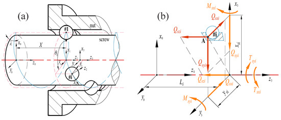
Figure 1.
(a) Coordinate systems on nut and screw, (b) resolution and simplification of contact load.
As shown in Figure 1b, the load of the i-th ball on the screw is decomposed into the coordinate system, as expressed in Equation (1).
When the left side of the nut bears a leftward pulling force, the nut is stretched and the screw is compressed. In the coordinate system, the axial elastic deformation of the screw and nut is given by Equation (2) [20].
Here, and are the internal forces experienced by the nut and the screw on the left side of the i-th ball’s contact point, as expressed in Equation (3).
Given that the nut’s length is significantly shorter compared to the screw’s length, and it is usually supported by two parallel linear guides, its elastic deformation is far less than the deflection of the screw. Hence, the radial elastic deformation of the nut is ignored. The deflection caused by the equivalent force and torque at each contact point of the screw can be represented by Equations (4) and (5), where , [20].
Taking the nut raceway as a reference, the equivalent axial deformation and radial deformation can be calculated by Equations (6) and (7), where is positive towards the positive side of the axis, and is positive in the positive direction of the axis [20].
Figure 2 represents the relationship between the equivalent deformation in and directions and the deformation of the ball. and are the centers of the nut and screw raceways, respectively. The deformation of the screw along the axis increases the ball’s elastic deformation, while deformation along the axis decreases the elastic deformation of the ball, and Equation (8) can be obtained. , , and are the components of the distance between the screw and nut raceways’ centers along the normal direction of the raceway, the axis, and the axis, respectively.
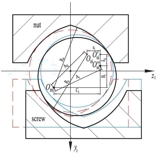
Figure 2.
Geometric deformation of the normal section of the raceway.
When the nut is subjected to a load, the relationship between , , , and the deformation and equivalent deformation can be calculated through Figure 2 by Equation (9). In addition, it can also be derived that . Because ball screws usually use Gothic raceway, and the elastic deformation of the screw and the nut is much smaller than their structural parameters, the contact angle does not change much before and after the load is applied [20].
From Equations (8) and (9), the relationship between the equivalent screw axial deformation and other deformations can be further derived. Here, the equivalent axial deformation is expressed as Equation (10) and then substituted into Equation (6) to obtain Equation (11).
By substituting Equations (2) and (9) into Equation (11), Equation (12) is obtained, where i = 2 ∼ N. Equation (12) consists of (N − 1) equations. We also need to introduce the axial force balance Equation (13) of the nut to solve for the contact loads of N balls, where , .
Equations (12) and (13) together form a set of nonlinear equations f, and can be numerically solved by Newton’s iteration using Equation (14) to obtain the contact loads of each ball, where is the solution of the contact load at the r-th iteration, J is the Jacobian matrix of the nonlinear function f, and the iteration ends when .
2.2. Elastic Perfectly Plastic General Model of Ball Screws
According to the point contact model of two free elastic bodies proposed by Hertz, when subjected to the normal load Q, the contact points of the two free elastic bodies form an elliptical contact deformation, with the elliptical surface perpendicular to the normal load. The distribution of the contact stress within the elliptical area of the point contact is given by Equation (15). The maximum Hertz contact stress is given by Equation (16).
The semi-major axis a, semi-minor axis b, and the elastic deformation of the contact deformation are given by Equations (17)–(19), where . , , , and can be obtained from Ref. [24].
Let , ; Equation (21) is obtained.
When the contact point reaches yield under the normal load, the semi-major and semi-minor axes of the contact ellipse are denoted as and , respectively. By substituting Equations (21) and (22) into Equation (16), the relationship between the elastic deformation and the yield stress at yield can be expressed as Equation (23).
Substituting Equation (23) into Equation (21), the yield contact load at the contact point can be expressed as Equation (24).
According to Thornton’s elastoplastic contact theory, the stress in the plastic deformation area of the contact point is regarded as a constant stress, which is less than the equivalent elastic stress. The stress distribution is related to the normal force and the strain quantity as shown in Figure 3.
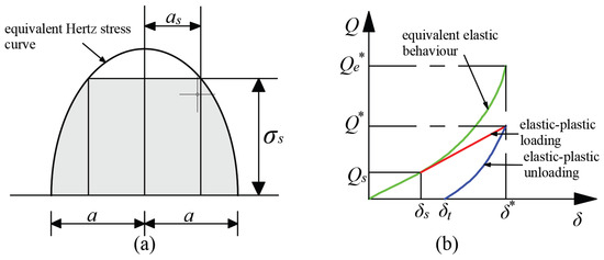
Figure 3.
The relationship between the stress distribution and the normal force and the strain quantity. (a) Thornton pressure distribution for elastic-perfectly plastic spheres. (b) Thornton force-relative approach relationship for elastic-perfectly plastic spheres.
The point on the equivalent elastic deformation curve is the starting point of the elastoplastic deformation loading curve, and the two are tangent at this point. According to Thornton’s assumption, the elastoplastic deformation loading curve is a straight line. Therefore, the slope of the elastoplastic deformation loading curve can be obtained by deriving the derivation at in Equation (19), which can be depicted as Equation (25).
Therefore, the elastoplastic loading and unloading deformation curve can be expressed as Equations (26) and (27).
At the unloading point , the stress shadow governed by the equivalent elastic contact load is the same as the stress shadow determined by the contact load . Because of the permanent plastic deformation of the surface, the equivalent elastic contact radius is smaller than the equivalent plastic radius. Therefore, can be expressed as Equation (28) [12]. Then, the numerical solution of can be obtained by combining Equations (26)–(28).
3. Result and Discussion
3.1. The Load Distribution and Plastic Deformation of the Ball Screw
The distribution of load is hard to measure directly in experiments due to the spatial constraints. To validate the accuracy of the proposed model, the parameters provided by Liu [20] are used, and the screw model is BSS3220-5E. The proposed model was compared with Liu’s results. In Liu’s model [20], the nut is at the screw’s midpoint; the screw’s left end is fixed, allowing only axial displacement, while the right end remains free. The load-bearing balls within the nut are assumed to be uniformly distributed along the helix. Under a 5000 N axial load applied to the screw’s left end, the load distributions calculated by the two are shown in Figure 4. It can be seen that the force on the balls inside the nut is uneven and the results of the proposed model match well with Liu’s results, with a maximum error of 8.86%. The reason for the certain error between the two results may be that Liu considered the variations in the contact angle with the different load.
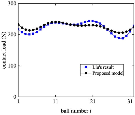
Figure 4.
Load distribution for the models in this paper and in Liu’s result [20].
To study the static load distribution of the ball screw, it is assumed that there is no pre-load. The distribution of loads under different lengths and loads is shown in Figure 5. With the change in the nut position on the screw, the distribution of loads also changes. The load distribution becomes uneven when the nut is positioned at the screw’s ends, whereas it becomes more uniform when the nut is situated at its midpoint. This is because the middle part of the screw is more deformable than the ends, so the distribution of loads at the screw’s middle position is more uniform than when the nut is located at the ends of the screw. The sequence number of the ball with the maximum load in the distribution of loads and the position of the nut at this time will not change with the change in the length of the screw. The shape of the distribution curve changes with the axial load. Additionally, with the difference in axial contact load, the size of the load distribution will also change; however, it does not have a significant impact on the shape of the distribution curve.
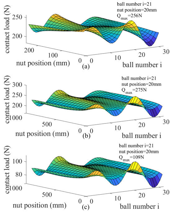
Figure 5.
The distribution of loads under different lengths and loads: (a) L = 300 mm = 5000 N (b) L = 1000 mm = 5000 N (c) L = 1000 mm = 2000 N.
Figure 6 shows the effect of the screw length on the static load. Assuming that the ball screw has no preload, the maximum load borne by the ball at different screw lengths is calculated. As the screw length increases, the maximum load borne by the ball also increases. This is because the longer the screw, the more easily it deforms under axial force, which results in an increase in the unevenness of the load borne by the ball.
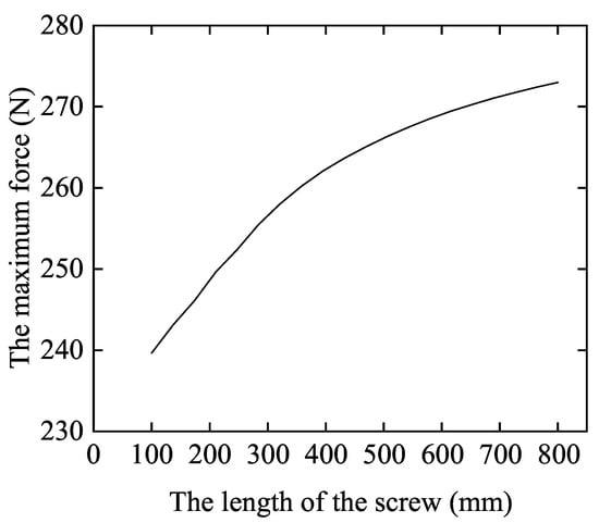
Figure 6.
The maximum load of the ball at different screw lengths.
Figure 7 shows the plastic deformation of the position when each ball contacts the ball screw raceway under different nut positions. It can be seen that the raceway’s plastic deformation changes with the nut position and the ball serial number due to the uneven stress of the ball.
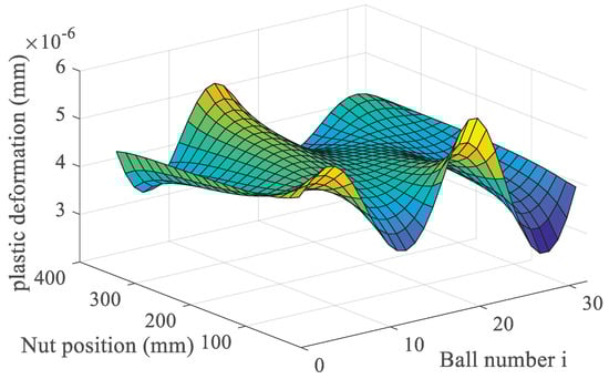
Figure 7.
The plastic deformation of the ball screw.
3.2. The Ball Screw’s Fatigue Elastic Life under the Ultimate Condition
The screw length and nut position influence the distribution of loads and, thus, the plastic deformation of its surface. Due to the uneven distribution of the ball load, it is necessary to calculate the stress of the maximum bearing ball, study the plastic deformation of the ball, and take this as the plastic deformation of the life study of the ball screw under the ultimate condition. The selected ball screw parameters and applied load are shown in Table 1. As Ref. [2] does not give the screw length, it is assumed here that the screw length is the nut length plus 30 mm.

Table 1.
Parameter table of the ball screws.
Figure 8 shows the relationship between the accumulative plastic deformation calculated in this paper and compares it with Gong’s test results [2]. The theoretical and experimental values of the accumulative plastic deformation of the four ball screws are in good agreement. The theoretical fatigue elastic life calculated in this paper and Gong’s experimental results and relative errors are shown in Table 2. The errors between theoretical values and experimental values of the four ball screws are less than 8%, and the relative errors calculated by Gong are less than 15%. Thus, the model introduced in the present study is correct and more accurate than Gong’s model.
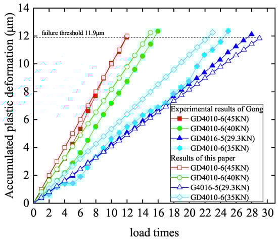
Figure 8.
The fatigue elastic life of ball screw in this paper and in Gong’s result.
Table 2.
Theoretical and experimental results of the fatigue elastic life.
Figure 9 shows the effect of different lengths and nut positions on the fatigue elastic life of ball screws. The maximum fatigue elastic life decreases with the increase of screw length. Moreover, the closer the nut is to two sections of the ball screw, the shorter the fatigue elastic life is. Figure 10 shows the ratio of nut position to ball screw length when the fatigue elastic life is the maximum under different lengths, loads, and ball screw models. When the fatigue elastic life of the screw is at its maximum, the ratio of the nut position to the screw length is around 0.7, and is not affected by the screw length, load, and model. The nut should therefore work in this position whenever possible.
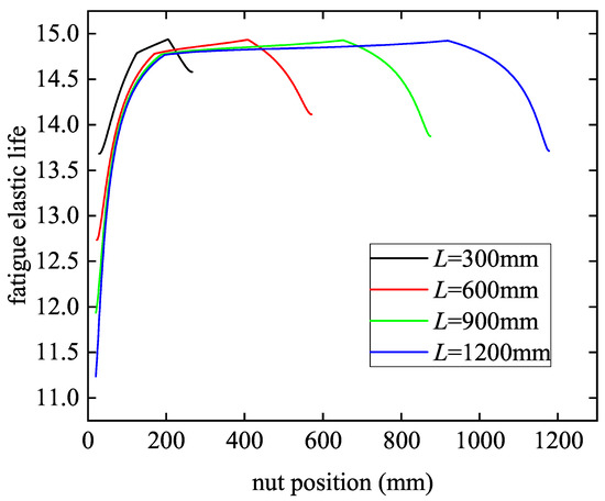
Figure 9.
The fatigue elastic life of ball screw under different nut positions and screw lengths.
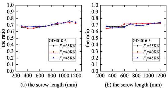
Figure 10.
The ratio of the nut position to the screw length under different parameters. (a) GD4010-6; (b) GD4016-5.
Figure 11 shows the maximum fatigue elastic life of ball screws under different contact angles, ball diameters, and conformity ratios when the lead screw length is 100 mm and 500 mm, respectively. The influence of ball screw parameters on the maximum fatigue elastic life under different lengths is the same. The fatigue elastic life increases approximately linearly with the increase of contact angle, but the effect is insignificant. With the increase of ball diameter, the fatigue elastic life increases, and the influence of ball diameter is larger. The fatigue elastic life decreases with the increase of the conformity ratio. Moreover, when the conformity ratio is small, its influence on the fatigue elastic life is very obvious. Therefore, selecting a larger ball diameter and a smaller conformity ratio can significantly improve the fatigue elastic life of the ball screw.
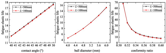
Figure 11.
The influence of different parameters on fatigue elastic life.
4. Conclusions
This paper calculates the load distribution of ball screws considering the nut position and the screw length. Based on the distribution of loads, the raceway plastic deformation is studied by Thornton’s elastoplastic theory. Finally, based on the concepts of plastic deformation and fatigue elastic life, the fatigue elastic life of the ball screw under the ultimate conditions is studied, and the influence of each parameter on the fatigue elastic life is studied. The following conclusions are drawn:
- (1)
- Under a static load, the ball screw’s load distribution surface remains relatively consistent despite increasing loads. The ball bearing the maximum force and the nut’s position do not change. Longer screws lead to higher maximum ball loads and increased force unevenness. The ball force is most uniform when the nut is in the middle, becoming uneven near the ends. Additionally, the plastic deformation of the screw raceway varies with the nut position and ball number.
- (2)
- The error between theoretical and experimental fatigue elastic life values in this study is less than 8%, validating the method. As screw length and load increase, ball screw fatigue elastic life decreases. Having nut positions closer to the screw ends also reduces fatigue elastic life. When the fatigue elastic life is at its maximum, the ratio of the nut position to the screw length is around 0.7 and is not affected by the screw length, load, and type. Operating the nut in this position is recommended.
- (3)
- With the increase of contact angle and ball diameter, the fatigue elastic life of the ball screw increases. With the increase in conformity ratio, the fatigue elastic life of the ball screw decreases. In addition, the ball diameter has a great influence on the fatigue elastic life; and when the conformity ratio is low, its influence on the fatigue elastic life is very obvious.
Author Contributions
Conceptualization, L.L. and C.L.; methodology, L.L.; validation, L.L. and W.W.; writing—original draft preparation, L.L.; writing—review and editing, S.C. and C.L.; supervision, S.C. and C.L. All authors have read and agreed to the published version of the manuscript.
Funding
This research received no external funding.
Institutional Review Board Statement
Not applicable.
Informed Consent Statement
Not applicable.
Data Availability Statement
Data are contained within the article.
Acknowledgments
This work was supported by the Key Laboratory of High-efficiency and Clean Mechanical Manufacture at Shandong University, the Ministry of Education, and the National Demonstration Center for Experimental Mechanical Engineering Education at Shandong University.
Conflicts of Interest
The authors declare no conflicts of interest.
Nomenclature
| Fatigue elastic life | |
| Ball diameter | |
| Plastic deformation | |
| Contact angle of the ball with screw raceway. | |
| , | Young’s modulus of the screw and nut. |
| , | Axial elastic deformation on the left side of the contact point between the i-th ball and the raceway of the screw and nut. |
| , | Force experienced by the screw and nut on the left side of the point of contact with the i-th ball. |
| Axial distance between the centers of two adjacent balls. | |
| I | Inertia moment of the screw. |
| The elastic deformation at yield. | |
| , L | The length of the screw and the distance between the i-th ball and the left end of the screw. |
| Equivalent radial deformation of screw. | |
| , | Component of the equivalent torque in the coordinate system . |
| Direction of the equivalent force and torque. . | |
| N | Number of working balls. |
| Pitch angle of ball screw. | |
| Q | Normal contact load |
| , | Poison’s ratio of the two contact bodies. |
| q | Stress distribution. |
| , | Deflection caused by the equivalent force and torque at each contact point. |
| Equivalent elastic contact load. | |
| Yield stress. | |
| Yield contact load. | |
| Maximum Hertz contact stress. | |
| Yield contact load. | |
| Azimuth angle of the i-th ball. | |
| , , | The component of the normal contact load of the i-th ball in the coordinate system . |
| a, b | Semi-major axis and the minor axis. |
| R | Raceway arc radius. |
| , , | Components of the distance between the centers of the screw and nut raceways along the normal direction of the raceway, axis, and axis. |
| , | Equivalent cross-section area of the screw and nut. |
| , | Horizontal and vertical coordinates of the contact point of the i-th ball with the screw in the coordinate system . |
References
- Zhou, C.; Zhou, H.; Feng, H. Experimental analysis of the wear coefficient of double-nut ball screws. Wear 2020, 446–447, 203201. [Google Scholar] [CrossRef]
- Gong, M.; Zhou, H.; Zhou, C.; Zhuang, H.; Feng, H. Study on fatigue elastic life of ball screw pair under ultimate load condition. Chin. J. Sci. Instrum. 2021, 42, 37–47. [Google Scholar] [CrossRef]
- Shimizu, S.; Shimoda, H.; Sharma, C.S. Re-evaluation of basic dynamic load rating and life formula for a ball screw. Tribol. Trans. 2007, 50, 88–95. [Google Scholar] [CrossRef]
- Mateo, A.; Llanes, L.; Akdut, N.; Anglada, M. High cycle fatigue behaviour of a standard duplex stainless steel plate and bar. Mater. Sci. Eng. A-Struct. Mater. Prop. Microstruct. Process. 2001, 319, 516–520. [Google Scholar] [CrossRef]
- Mateo, A.; Llanes, L.; Akdut, N.; Stolarz, J.; Anglada, M. Anisotropy effects on the fatigue behaviour of rolled duplex stainless steels. Int. J. Fatigue 2003, 25, 481–488. [Google Scholar] [CrossRef]
- Balitskii, A.I.; Vytvytskyi, V.I.; Ivaskevich, L.M. The low-cycle fatigue of corrosion-resistant steels in high pressure hydrogen. Procedia Eng. 2010, 2, 2367–2371. [Google Scholar] [CrossRef][Green Version]
- Rezayat, M.; Roa, J.J.; Mateo, A. Effect of Laser Surface Texturing on Schmid Factor and Plastic Deformation Mechanisms on AISI 301LN Steel. Metals 2023, 13, 1789. [Google Scholar] [CrossRef]
- Rezayat, M.; Rovira, J.; Garcia, A. Phase transformation and residual stresses after laser surface modification of metastable austenitic stainless steel. In Proceedings of the Advances in Fracture and Damage Mechanics XX, Malaga, Spain, 5–7 September 2022; p. 020005. [Google Scholar] [CrossRef]
- Li, Y. Design of Typical Disposable Mechanical Elements and Application Research. Ph.D. Thesis, Harbin Institute of Technology, Harbin, China, 2013. [Google Scholar]
- Mei, X.; Tsutsumi, M.; Tao, T.; Sun, N. Study on the load distribution of ball screws with errors. Mech. Mach. Theory 2003, 38, 1257–1269. [Google Scholar] [CrossRef]
- Wei, C.; Lin, J. Kinematic analysis of the ball screw mechanism considering variable contact angles and elastic deformations. J. Mech. Des. 2003, 125, 717–733. [Google Scholar] [CrossRef]
- Braccesi, C.; Landi, L. A general elastic-plastic approach to impact analisys for stress state limit evaluation in ball screw bearings return system. Int. J. Impact Eng. 2007, 34, 1272–1285. [Google Scholar] [CrossRef]
- Bertolaso, R.; Cheikh, M.; Barranger, Y.; Dupre, J.C.; Germaneau, A.; Doumalin, P. Experimental and numerical study of the load distribution in a ball-screw system. J. Mech. Sci. Technol. 2014, 28, 1411–1420. [Google Scholar] [CrossRef]
- Lin, B.; Okwudire, C.E.; Wou, J.S. Low Order Static Load Distribution Model for Ball Screw Mechanisms Including Effects of Lateral Deformation and Geometric Errors. J. Mech. Des. 2018, 140, 022301. [Google Scholar] [CrossRef]
- Hu, J.; Wang, M.; Zan, T. The kinematics of ball-screw mechanisms via the slide-roll ratio. Mech. Mach. Theory 2014, 79, 158–172. [Google Scholar] [CrossRef]
- Brecher, C.; Esser, B.; Falker, J.; Kneer, F.; Fey, M. Modelling of ball screw drives rolling element contact characteristics. CIRP Ann.-Manuf. Technol. 2018, 67, 409–412. [Google Scholar] [CrossRef]
- Zhao, J.; Lin, M.; Song, X.; Jiang, H. Research on the precision loss of ball screw with short-time overload impact. Adv. Mech. Eng. 2018, 10, 1687814018817902. [Google Scholar] [CrossRef]
- Zhao, J.; Lin, M.; Song, X.; Guo, Q. Investigation of load distribution and deformations for ball screws with the effects of turning torque and geometric errors. Mech. Mach. Theory 2019, 141, 95–116. [Google Scholar] [CrossRef]
- Zhao, J.; Lin, M.; Song, X.; Zhao, Y.; Wei, N. A novel approach to predict the precision sustainability of ball screw under multidirectional load states. Proc. Inst. Mech. Eng. Part C-J. Mech. Eng. Sci. 2021, 235, 1277–1296. [Google Scholar] [CrossRef]
- Liu, C.; Zhao, C.; Meng, X.; Wen, B. Static load distribution analysis of ball screws with nut position variation. Mech. Mach. Theory 2020, 151, 103893. [Google Scholar] [CrossRef]
- Sangalli, L.; Oyanguren, A.; Larranaga, J.; Arana, A.; Izquierdo, M.; Ulacia, I. Numerical characterization of local and global non-uniformities in the load distribution in ball screws. Int. J. Adv. Manuf. Technol. 2022, 118, 1411–1425. [Google Scholar] [CrossRef]
- Zhao, J.; Zhao, C.; Jiang, Z.; Liu, C.; Xu, M.; Wen, B.C. Static model and reliability analysis of double nut ball screw considering screw bending. Tribol. Int. 2023, 187, 108733. [Google Scholar] [CrossRef]
- Okwudire, C.E.; Altintas, Y. Hybrid Modeling of Ball Screw Drives with Coupled Axial, Torsional, and Lateral Dynamics. J. Mech. Des. 2009, 131, 071002. [Google Scholar] [CrossRef]
- Wei, C.; Lin, J.; Horng, J. Analysis of a ball screw with a preload and lubrication. Tribol. Int. 2009, 42, 1816–1831. [Google Scholar] [CrossRef]
Disclaimer/Publisher’s Note: The statements, opinions and data contained in all publications are solely those of the individual author(s) and contributor(s) and not of MDPI and/or the editor(s). MDPI and/or the editor(s) disclaim responsibility for any injury to people or property resulting from any ideas, methods, instructions or products referred to in the content. |
© 2024 by the authors. Licensee MDPI, Basel, Switzerland. This article is an open access article distributed under the terms and conditions of the Creative Commons Attribution (CC BY) license (https://creativecommons.org/licenses/by/4.0/).