Article

Exploring the Distribution Characteristics of High Static Load in the Island Working Face of Extra-Thick Coal Seams with Hard Roof: Addressing the Challenge of Rock Burst Risk

College of Mining Engineering, Taiyuan University of Technology, Taiyuan 030024, China
*
Author to whom correspondence should be addressed.
Appl. Sci. 2024, 14(5), 1961; https://doi.org/10.3390/app14051961
Submission received: 3 February 2024 / Revised: 20 February 2024 / Accepted: 23 February 2024 / Published: 28 February 2024
(This article belongs to the Special Issue Advanced Underground Coal Mining and Ground Control Technology)

Abstract

:
A high static load state significantly increases the risk of rock burst occurrences on the island working face, posing a significant threat to the safety of coal mine production. This paper focused on the engineering background of the 8204-2 working face at Tashan Coal Mine. Field research indicated that there were noticeable differences in the frequency of coal bursts in different regions and working face ranges, with the mine pressure being complex and severe. Through theory analysis, the stress concentration degree of the island working face was mainly affected by the buried depth, working face length, gob length, coal seam thickness, and coal pillar width. The stress distribution and plastic zone changes of the island working face, influenced by different factors, were studied by numerical simulation. The entity coal stress equation of the island working face was fitted and the mechanism of rock burst in the island working face was revealed. The research findings presented in this paper provide important theoretical support and technical guidance for the safe and efficient mining of island working faces.

1. Introduction

In recent decades, coal has been a vital primary energy source and has played a foundational role in the global energy supply along with oil and natural gas. Coal supplies provide for around one-third of the world’s energy. Coal will continue to play a significant role in the global energy structure and support the stability and security of the energy supply for a considerable period of time [1,2]. With the continuous mining of coal resources, coal mining conditions are becoming more and more complex. The geological structure division and the need for safe mining require the use of the jump mining method between working faces in the mining area, resulting in the formation of various types of island working faces [3,4,5]. Due to the continuous and complete structure of the overlying strata on an isolated island working face, the pressure on an island working face is greater than that on a non-island working face [6,7]. This high stress concentration leads to severe mine pressure and substantial damage to the surrounding rock of the roadway, as illustrated in Figure 1. The dynamic disaster of rock burst is highly likely to occur, posing a serious threat to mining of coal resources. This is primarily due to the high static load on the island working face itself, the presence of extra-thick coal seams, and the disruptive effects caused by hard roofs in the process of mining [8,9,10,11].
Since one of the dominant factors of rock burst in an island working face is a high static load, the most straightforward approach is to measure the stress distribution features in the field. At present, the commonly used methods for monitoring the stress of the working face include: stress sensor monitoring [12,13], hydraulic sensor monitoring [14], acoustic emission monitoring [15,16], electromagnetic radiation monitoring [17,18,19], microseismic monitoring [19,20,21,22], and deformation monitoring [23,24]. These methods provide a large amount of field data for predicting and preventing rock bursts in island working faces.
Dou et al. categorized the overburden structure of the island working face into three types: a symmetrical short-arm T-shaped structure, symmetrical long-arm T-shaped structure, and asymmetrical T-shaped structure. These divisions are based on the key strata theory and field microseismic monitoring [7]. In light of this, Jia et al. employed a comparable simulation to examine the coal pillar deformation characteristics and the mode of failure of the overlying strata during the mining process of the island working face with thick and hard key strata. They also discovered the mechanism underlying a rock burst caused by an island working face’s symmetrical long arm T-shaped structure [25]. Through the analysis of mining scale and settlement results, Wen et al. concluded that the overlying low key strata of an island working face with the long-arm T-shape are mainly controlled the microseismic activity and mining stress response of the working face [4]. Based on the load transfer mechanism, Zhu et al. derived a series of formulas for the average static stress and dynamic stress of island coal pillars through theoretical analysis [26]. Liu et al. obtained some reasonable early warning parameters through the stress field distribution law of island working faces [27]. Xu et al. investigated the stress distribution, deforestation features, and plastic zone distribution features of the roadway and coal pillar in an island working face during mining with the use of numerical modeling [28]. Liu et al. examined the distribution law of the advanced pressure of the working face during the first mining period and the regular advancing period, as well as the variation law of the stress field of the overlaying strata of the island working face [29]. Wang et al. studied the dynamic characteristics of the energy release of the coal and rock mass in an island working face and revealed the mechanism of an energy release surge in front of a working face [30].
A high static load is the main cause of rock bursts on an island working face, and the aforementioned works contribute to this theoretical framework further and serve as a valuable reference for the follow-up research [8,31,32]. The diversity of occurrence conditions of island working faces leads to different stress concentration degrees in different forms of island working faces. Therefore, it is very important to analyze the distribution characteristics of a high static load in island working faces by combining various factors.
However, there is a lack of research on the distribution characteristics of high static load in different occurrence forms of island working faces. Therefore, this study focused on the 8204-2 working face of Tashan Coal Mine in the Datong mining area. Through theoretical analysis and numerical simulation, we analyzed five factors that influence the distribution characteristics of a high static load in an island working face. This research aimed to enhance the safety and efficiency of coal production by preventing and controlling rock bursts in island working faces.

2. High-Stress Appearance of Island Working Face

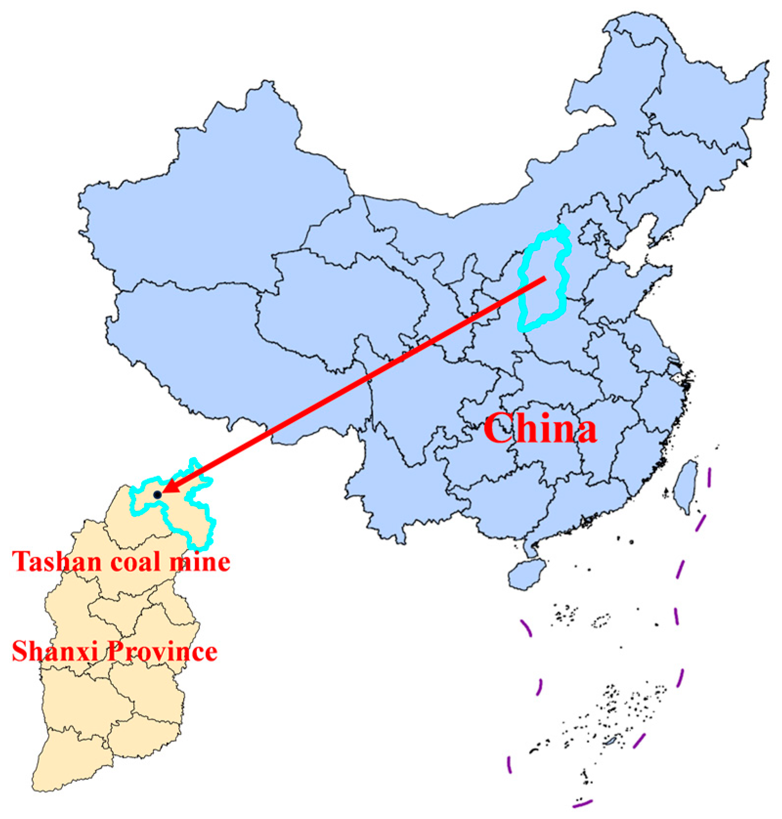
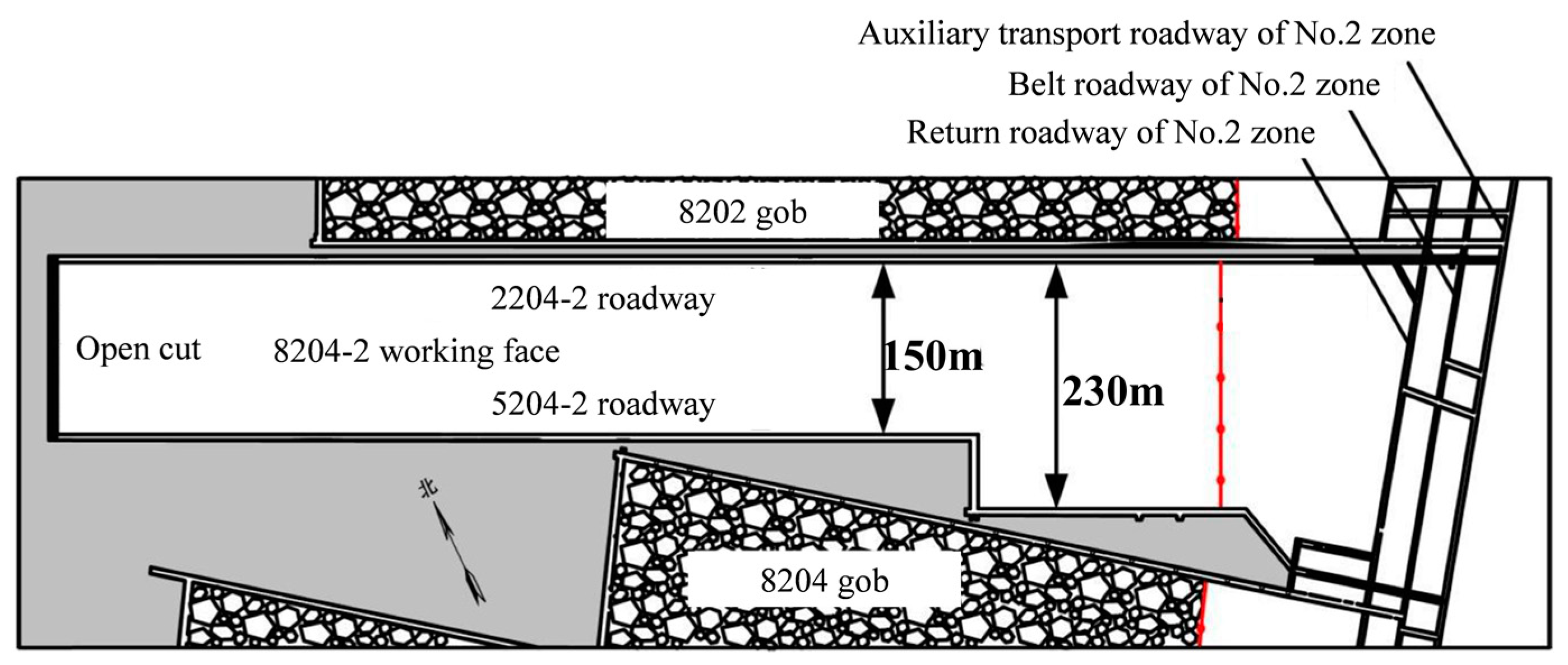
2.1. Engineering Geological Conditions

The Tashan Coal Mine is situated in Da-tong City, Shanxi Province, China, at the eastern edge of the Datong Coalfield (Figure 2). The 8204-2 working face at the Tashan Coal Mine is an island working face that operates within a mining engineering environment characterized by complexity and variability. This environment has experienced continuous changes in the width of the coal pillar section. The mining engineering environment of the working face is intricate and subject to variations. The working face has undergone a continuous stage of change in the width of the section coal pillar. On the northeastern side of the 8204-2 working face, there is a proximity to the 8202 gob, resulting in an 8 m coal pillar. On the southwest side, there is the 8204 gob, where the width of two coal pillars undergoes continuous changes. The coal seam being mined is nearly horizontal, with an inclination range of 1~3°. The 8204-2 working face is mining coal from the Carboniferous 3-5 # coal seam. The average depth of burial is 517 m, the average thickness of the coal seam is 14.1 m, the mining height is 3.8 m, and the amount of caving is 11.2 m. The length of the working face being mined is 1600 m. The 8204-2 working face is a variable length working face, with an initial mining length of 150 m and a later mining length of 230 m. Figure 3 illustrates the layout of the 8204-2 working face.

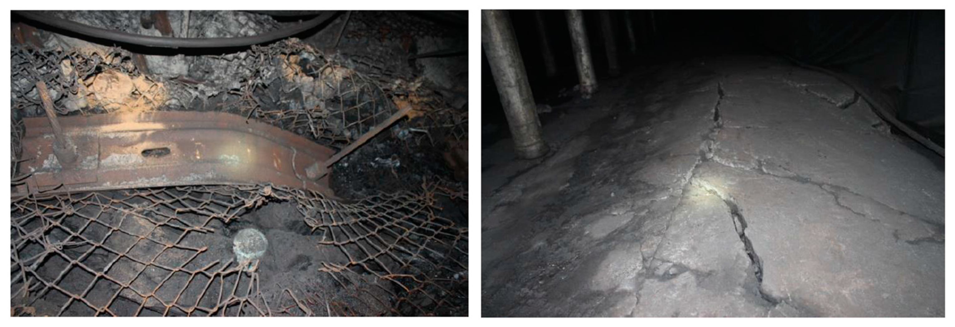
2.2. Appearance of Dynamic Phenomenon

Before a coal burst occurs, the coal pillar experiences a high energy state as a result of high static load; therefore, observation of the mine pressure in the field roadway can roughly judge the static load degree of the island working face at this time. Coal burst is the sound produced by the movement or destruction of coal rock. This means that the energy accumulated in the coal rock mass is released instantaneously.
The field manual collection method was used to count the occurrence of dynamic phenomena such as roadway spalling, roof fall, floor heave, and coal burst during the excavation of the 5204-2 roadway (Figure 4). After eight months of continuous monitoring, the recorded data were collated and analyzed. The confirmation basis of the ‘coal burst’ event was that the rock surrounding the roadway emitted a similar ‘shotting’ sound. The confirmation basis of the coal burst grade as ‘relatively strong’ was based on the huge sound of the roof, accompanied by significant vibration, roof slurry peeling, and other phenomena, and the coal burst frequency of the coal burst phenomenon was more than 20 times. After continuous monitoring and data collation during the excavation period, the relationship between the dynamic phenomenon of the roadway and the width of the coal pillar during the excavation of the widened coal pillar area was obtained, as shown in Figure 5.
The dynamic phenomena during the roadway excavation in the coal pillar widening zone had the following characteristics:
(1) A total of 531 times of coal blasting occurred during the tunneling of the first coal pillar widening zone:
8.2 m~33.5 m: The number of coal bursts was 10.44 times a day, and the number of relatively strong coal bursts was 2.69 times a day;
3.6 m~7.9 m and 33.5 m~56 m: The number of coal bursts was 1.67 times a day, and the number of relatively strong coal bursts was 0.18 times a day;
(2) A total of 2176 times of coal blasting occurred during the tunneling of the second coal pillar widening zone:
22.4 m~64.4 m: The number of coal bursts was 19.54 times a day, and the number of relatively strong coal bursts was 4.38 times a day;
47.9 m~50.6 m: The number of coal bursts was 8.72 times a day, and the number of relatively strong coal bursts was 1.89 times a day;
68 m~64.4 m and 22.4 m~6 m: The number of coal bursts was 1.53 times a day, and no relatively strong coal burst occurred.
In summary, it can be found that the dynamic phenomenon of mine pressure in the island working face is severe, and there are obvious high static load characteristics. In the first coal pillar widening zone, the phenomenon of coal burst mainly occurred in the range of 8.2 m~33.5 m during tunneling. In the second coal pillar widening zone, the phenomenon of coal burst was more frequent during tunneling. In different regions and ranges, there are noticeable variations in the frequency of coal bursts and the occurrence of relatively strong coal bursts. This suggests that the high static load on an island working face is related to the specific characteristics of each region.

3. Influencing Factors of High Static Load in Island Working Face

Because the key strata on the long-arm T-shaped island working face remain intact, the main key strata maintain continuity and integrity; that is, the continuous bearing effect of the upper load is maintained, and part of the load above the gob is transferred to the island working face, resulting in the pressure of the coal rock in the island working face being greater than that in the non-island working face. The primary key stratum can be thought of as a continuous beam structure, with the three supporting points of the continuous beam structure—the coal rock of the island working face, the coal rock outside the gob on both sides, and the above strata together—bearing the strata above it [33,34,35]. The structural characteristics of the overburden rock in an island working face are shown in Figure 6.
According to the assumption made of the continuous beam structure of the island working face, the total bearing force of the isolated island coal is considered equal to the support point force at the middle of the continuous beam structure. The middle support point is positioned in the middle of the island coal body, while the support points at both ends are located at the boundary of the gob. l1 represents the length of the gob, l2 denotes the length of the isolated island coal, and l3 represents the distance between the middle fulcrum and the two side fulcrums. If we assume that the total load in the island working face is equivalent to the hinged support point force in the middle of the continuous beam structure of the overlying strata, the concentrated stress F of the island working face can be calculated [34]:
F = P L ( L 2 + l 3 2 2 L l 3 2 ) 8 L l 3 2
where P is the uniform load on the continuous beam structure, which is regarded as the stress of the original rock of the coal seam. L is the total span of the continuous beam structure. l3 is the distance between the middle fulcrum and the two sides of the fulcrum.
The impact of the working face length, gob length, and buried depth on the concentrated stress F of the island working face can be observed in Equation (1).
The stress distribution of the island working face also depends on the thickness of the coal seam according to the limit equilibrium theory, as shown in Figure 7. The width of the limit equilibrium zone of the coal pillar in the gob can be obtained; that is, the distance between the abutment pressure peak value and the edge of the coal pillar is [35,36]:
x o = m 2 ξ f l n K γ H + C c o t φ ξ ( p 1 + C c o t φ )
where m is the thickness of the coal seam, K is the stress concentration coefficient, f is the friction coefficient of the coal seam between the roof and floor, φ is the friction angle of the coal, C is the cohesion of the coal, γ is the volume weight of the overburden rock, H is the burial depth, p is the lateral support force, and ξ is the triaxial stress coefficient.
Different widths of the coal pillar lead to varying stress distribution states in the island working face [37,38]. In Figure 8a, when a large coal pillar is present, it results in a saddle-shaped stress distribution, with a wide elastic zone in the middle of the coal pillar. The coal pillar itself can withstand higher support pressure, resulting in smaller peak stress in the island working face. On the other hand, in Figure 8b, when a small coal pillar is present, it gets destroyed and unloaded, leading to a single peak stress distribution in the coal pillar. The elastic core in the middle of the coal pillar decreases, while the plastic zone surrounding the coal pillar increases. This results in higher support pressure on the deeper part of the island working face.
In summary, the stress distribution of the island working face is primarily influenced by five factors: buried depth, working face length, gob length, coal seam thickness, and coal pillar width. Therefore, the influence of these five factors on the stress distribution of an island working face under various conditions was studied by numerical simulation.

4. Stress Distribution Law in Island Working Face

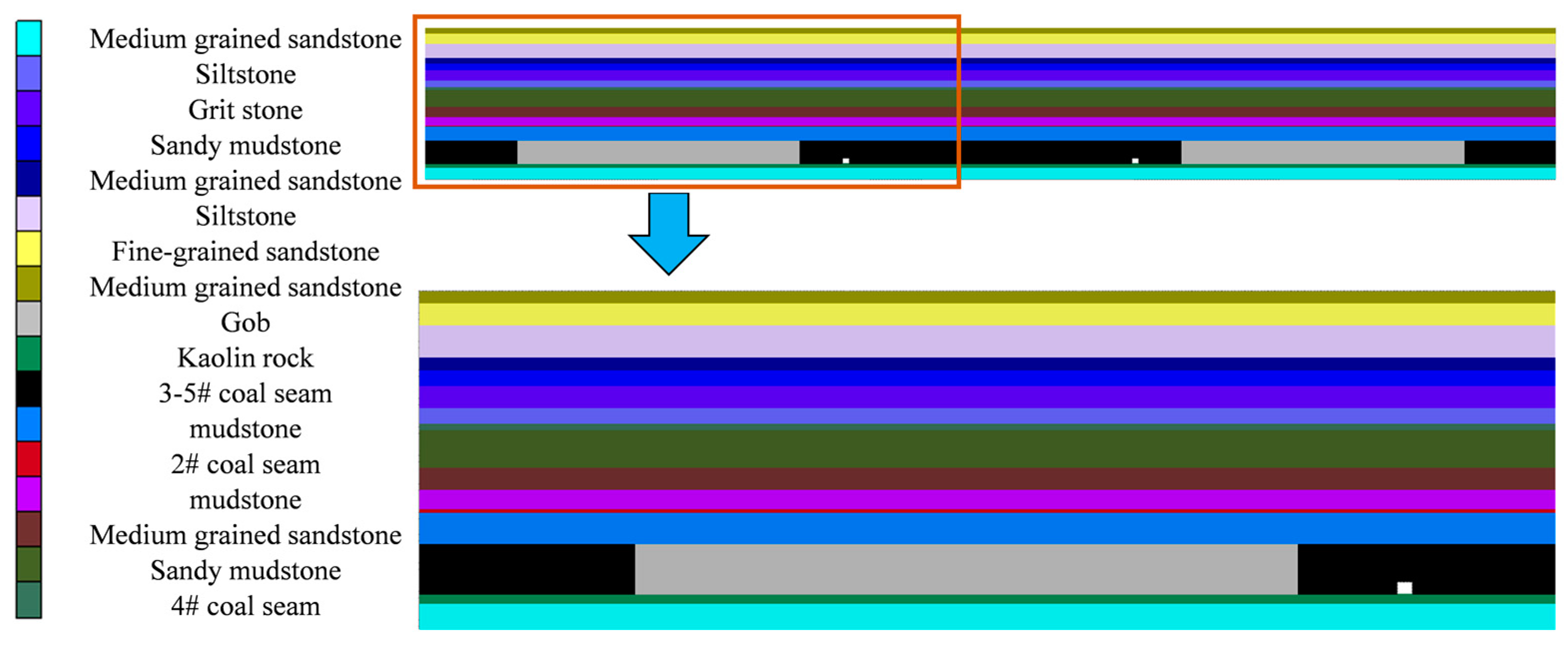
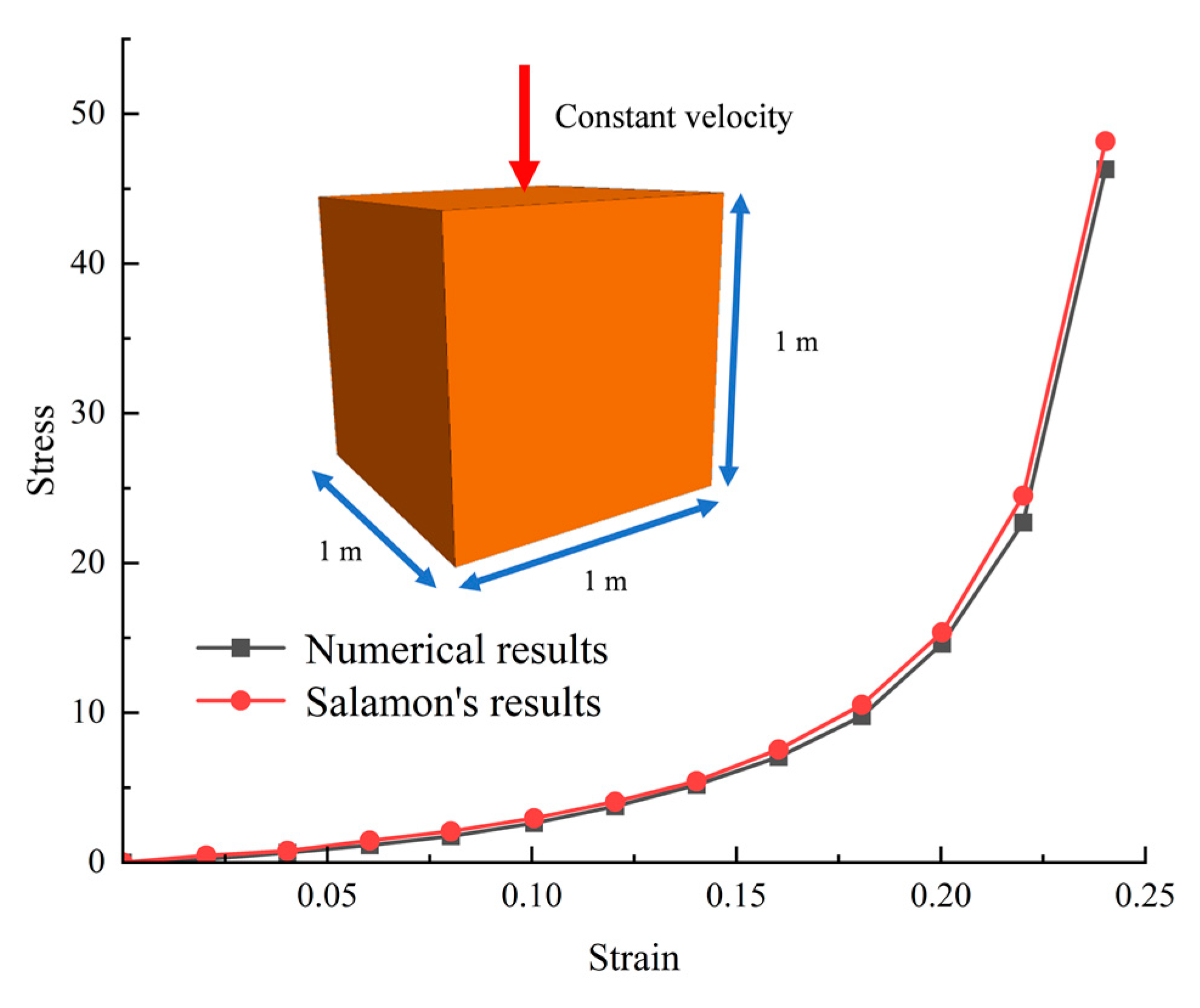
4.1. Construction of Numerical Model

The island working face model of a symmetric gob was constructed using the numerical simulation program Flac3D (6.0) based on the project overview and theoretical analysis presented above. The impact of five factors on the stress distribution state of the island working face under various conditions was investigated, as shown in Figure 9. The model size was designed under the condition that the length of the gob is 200 m: 800 × 200 × 10. To release the influence of the boundary, the boundary of the model was set with a 65 m width of coal pillar. The roadway had a height of 4 m and a width of 5 m. Fixed boundaries were set around and at the top of the model, and vertical stress was applied to the upper boundary of the model to simulate the overlying pressure based on the rock density of 0.025 MN/m.
The mechanical parameters of the coal seam in the field were obtained in the laboratory, and the parameters of the 3-5 # coal seam were calibrated by numerical simulation using the Strain–Softening model, so that more realistic mechanical parameters of the coal body were obtained, as shown in Figure 10. The horizontal stress applied in the X and Y directions was 1.2 times the vertical stress. The Mohr–Coulomb model was applied to the coal and rock mass. The mechanical parameters of the coal and rock mass are shown in Table 1. Based on the Double-Yield model [39], the filling compaction of gangue in the gob was simulated and the mechanical parameters of the gob are shown in Table 2, and the stress–strain curves based on the simulation and Salamon’s model are shown in Figure 11. To study the stress distribution feature of the island working face under different combinations of influencing factors, the four values were kept constant. The fifth study used four different values, for a total of 16 sets of simulation experiments. The experimental scheme is shown in Table 3.

4.2. Numerical Simulation Results Analysis

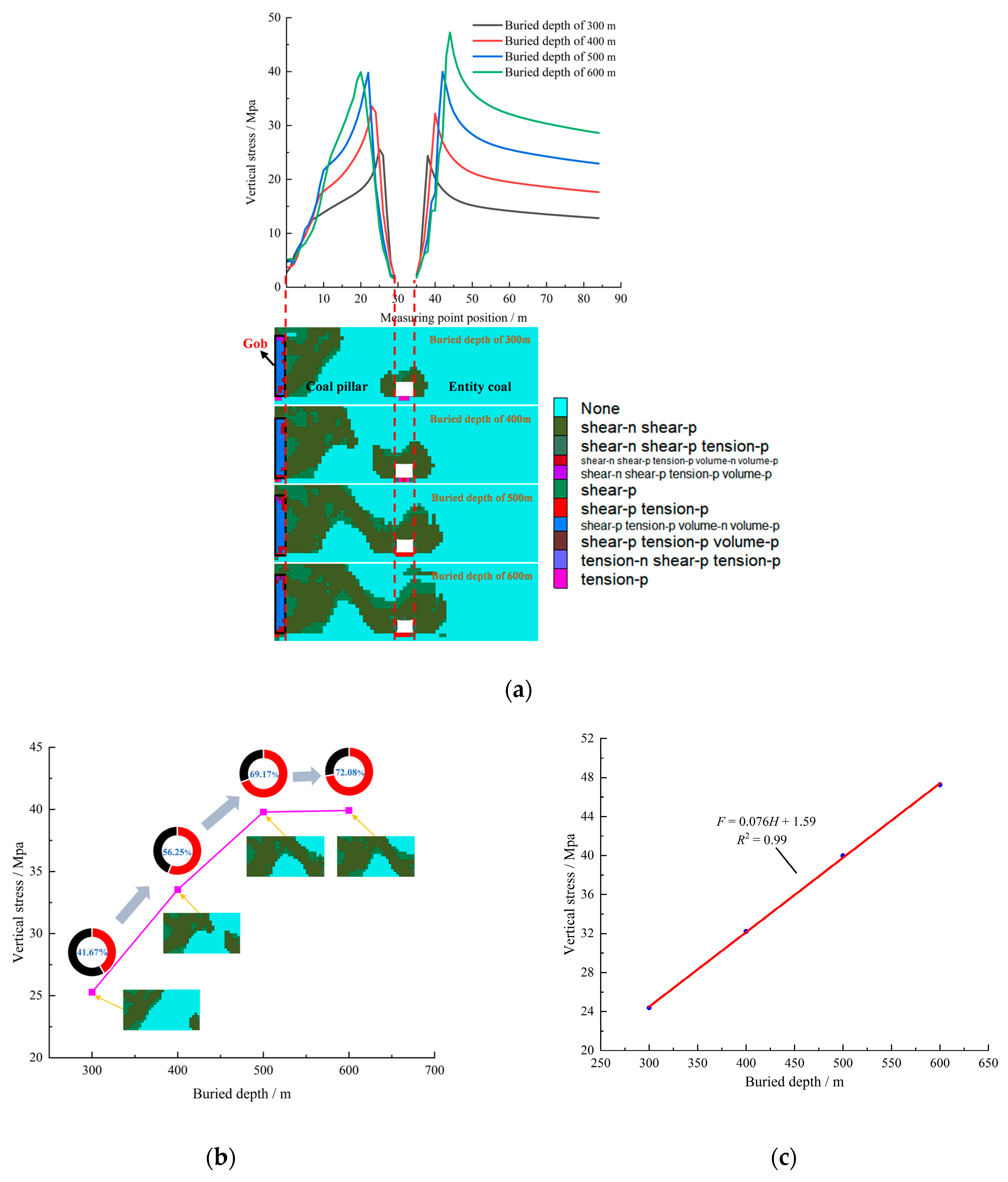
4.2.1. The Stress Distribution Influenced by Buried Depth

Under different buried depth conditions, we simulated the stress distribution characteristics of the island working face, and the results are shown in Figure 12a. With the increase of the buried depth of the coal seam, the plastic zone range of the roadway surrounding the rock and coal pillar in the island working face shows a trend of gradual expansion, and the peak stress is also gradually increasing. It is worth noting that with the increase of buried depth, the position of the stress peak is also moving to the center of coal pillar and the deep part of the entity coal. Figure 12b shows the stress variation law of the coal pillar and the evolution characteristics of the plastic zone under different buried depths conditions. It is evident from the figure that when the buried depth is 300 m, 400 m, 500 m, and 600 m, the total proportion of the number of grids in the plastic zone proportion of the coal pillar is 41.67%, 56.25%, 69.17%, and 72.08%, respectively, and the corresponding peak stress of the coal pillar is 25.6 Mpa, 33.5 Mpa, 39.8 Mpa, and 40 Mpa, respectively, When the coal pillar width is 30 m, it still shows good bearing capacity. However, when the buried depth increases to 500 m and 600 m, the difference between the plastic zone and the peak stress of the coal pillar gradually decreases, and the change trend gradually becomes gentle. This phenomenon may imply that the coal pillar is close to its maximum bearing limit. Figure 12c shows the variation law of the peak stress of the entity coal under different buried depths. It is evident from the figure that with the increase of the buried depth, the peak stress of the island working face is 24.4 Mpa, 32.2 Mpa, 40 Mpa, and 47.3 Mpa, respectively, showing an obvious increasing trend. This change rule shows that there exists a direct correlation between the peak stress of the entity coal and the buried depth; that is, with the increase of the buried depth, the stress of the entity coal will increase accordingly. Therefore, compared with shallow coal seams, deep coal seams are more prone to disasters such as rock burst. This conclusion provides an important basis for us to deeply understand and evaluate the mining safety of deep coal seams. In practical engineering, we need to fully consider the buried depth conditions, and take effective stress management measures and technical means to guarantee the safety and efficiency of deep coal seam mining.

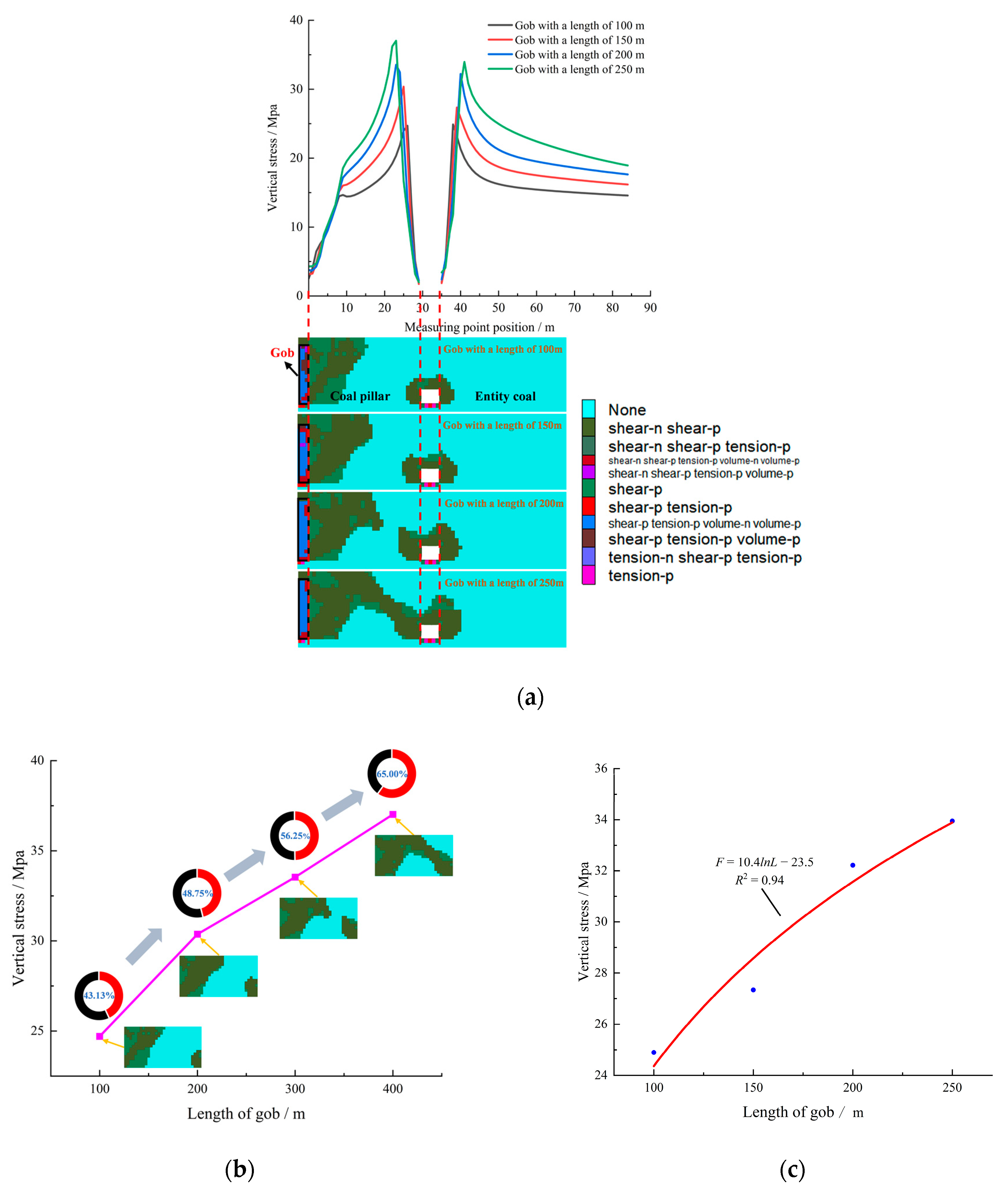
4.2.2. The Stress Distribution Influenced by Adjacent Gob Length

Under different lengths of the gob conditions, the stress distribution characteristics of the island working face are simulated, as shown in Figure 13a. The plastic zone range of the surrounding rock and the coal pillar of the roadway in the island working face gradually increases with an increasing length of the gob, and the peak stress gradually increases and moves to the center of the coal pillar and the deep part of the working face. Figure 13b shows the variation law of the coal pillar stress and the evolution characteristics of the plastic zone under different gob conditions. It can be seen from the figure that when the length of the gob is 100 m, 150 m, 200 m, and 250 m, the total proportion of grids in the plastic zone proportion of the coal pillar is 43.13%, 48.75%, 56.25%, and 65.00%, respectively, and the corresponding peak stress of the coal pillar is 24.7 Mpa, 30.3 Mpa, 33.5 Mpa, and 37 Mpa, respectively, all of which show a gradual increasing trend. Within the length of the gob, although the proportion of the plastic zone of the coal pillar is increasing, a coal pillar with a width of 30 m still has good bearing capacity. It can bear greater stress without failure and instability.
The relationship between the peak stress of the entity coal and the length of the gob is shown in Figure 13c. The peak stress of the isolated island working face is 24.9 Mpa, 27.3 Mpa, 32.2 Mpa, and 33.9 Mpa, respectively, showing a gradual increasing trend. With the increase of the gob length, the damage range of the overlying strata in the gob is correspondingly expanded, resulting in more overlying strata gravity transferring to the underlying coal body. Although the proportion of the plastic zone range of the coal pillar is gradually increasing, there are still enough elastic cores inside it, showing good bearing capacity. Therefore, the stress of the coal pillar is also increasing. At the same time, the stress on the entity coal is also increasing accordingly, and this stress gradually expands to the deep coal seam. This series of changes shows that when the range of gobs on both sides increases, the stress concentration degree of the island working face will also increase. Therefore, it is crucial to carefully arrange the mining area layout in the mining design to minimize the presence of large gob areas. This strategy aims to decrease the level of stress concentration and enhance the safety of working face mining.

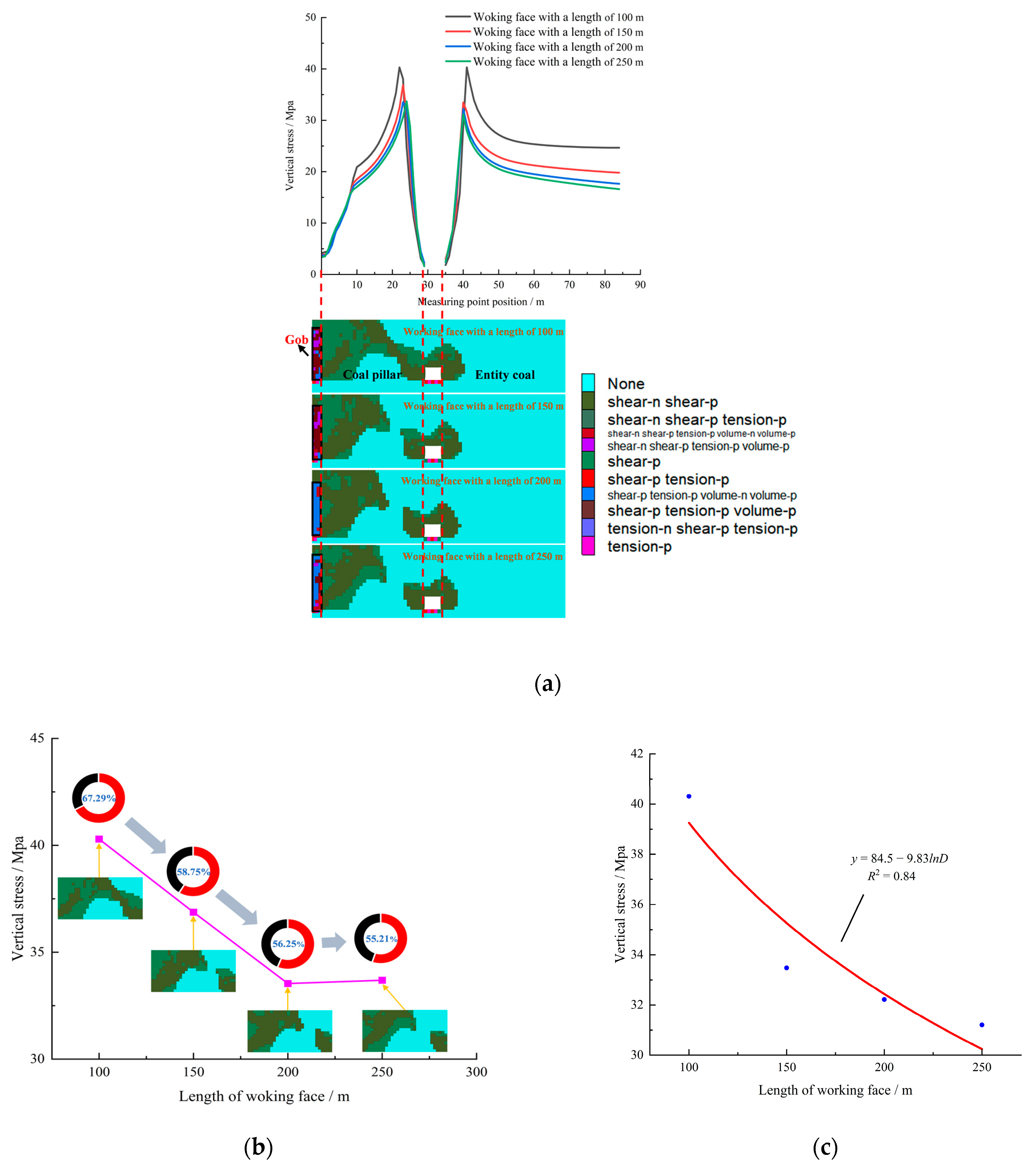
4.2.3. The Stress Distribution Influenced by Working Face Length

For different working face lengths, the stress distribution characteristics of the island working face are obtained by simulation, as shown in Figure 14a. The plastic zone range of roadway surrounding the rock and coal pillar decreases gradually with the increase of working face length, and the peak stress of the isolated island working face decreases gradually. Figure 14b shows the variation law of the coal pillar stress and the evolution characteristics of the plastic zone under different working face lengths, which indicates that when the length of the working face is 100 m, 150 m, 200 m, and 250 m, the total proportion of the number of grids in the plastic zone proportion of the coal pillar proportion is 67.29%, 58.75%, 56.25%, and 55.21%, respectively, and the corresponding peak stress is 40.2 Mpa, 36.9 Mpa, 33.5 Mpa, and 33.7 Mpa, respectively, which is roughly decreasing. The variation law of the peak stress of the entity coal under different working face lengths is shown in Figure 14c. The peak stress of the entity coal is 40.3 Mpa, 33.8 Mpa, 32.2 Mpa, and 31.2 Mpa, respectively, which decreases gradually with the increase of working face length. The analysis results show that with the increase of the length of the working face, the bearing stress range of the entity coal itself is more widely distributed, while the stress of the coal pillar is relatively reduced. This phenomenon shows that increasing the length of the working face helps to reduce the abutment stress of the entire island working face. Therefore, in the design and planning of island working faces, we should try to avoid the working face length being too small to reduce the risk of an induced rock burst. At the same time, it is necessary to reasonably increase the length of the working face, but it should be noted that the length of the working face should not be too long, so as not to adversely affect the mining efficiency.

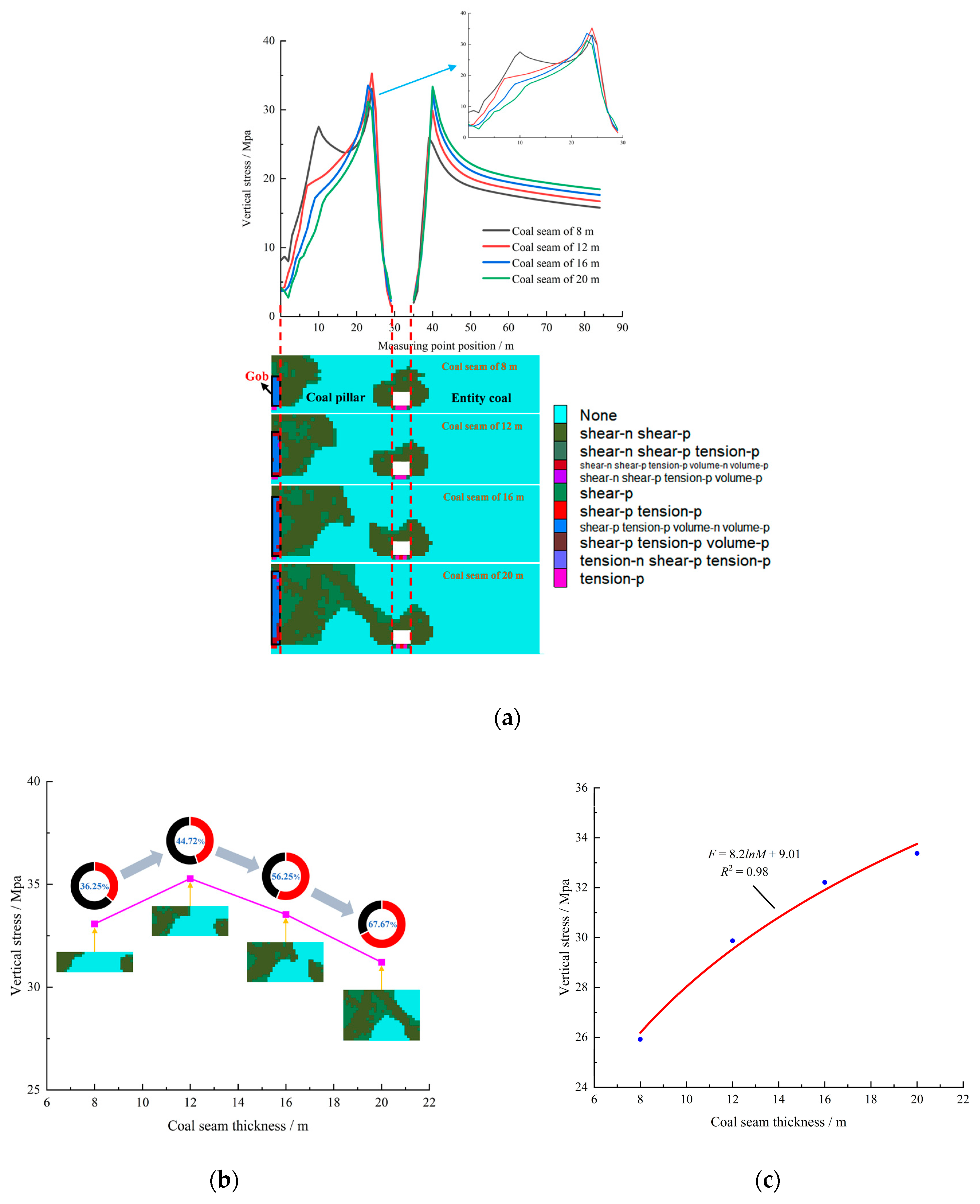
4.2.4. The Stress Distribution Influenced by Coal Seam Thickness

The stress distribution features of the island working face were simulated under different coal seam thickness conditions, as shown in Figure 15a. The simulation results indicate that with the increase of coal seam thickness, the plastic zone of the roadway surrounding the rock and coal pillars in the island working face shows a trend of gradual expansion. When the thickness of the coal seam reaches 8 m, the stress distribution of the coal pillar shows a unique bimodal feature, and the stress peaks on both sides are 27.6 Mpa and 33.1 Mpa, respectively. Figure 15b shows the variation law of the coal pillar stress and the evolution characteristics of the plastic zone under different coal seam thickness conditions. The simulation results indicate that when the coal seam thickness is 8 m, 12 m, 16 m, and 20 m, the total proportion of the number of coal pillar plastic zone proportions is 36.25%, 44.72%, 56.25%, and 67.67%, respectively, and the corresponding peak stress is 33.1 Mpa, 35.3 Mpa, 33.5 Mpa, and 31.2 Mpa, respectively. Under the condition of an 8 m thick coal seam, a significant elastic core is formed in the center of the coal pillar, which is the embodiment of the strongest bearing capacity of the coal pillar. Therefore, the stress distribution of the coal pillar in this state shows a clear bimodal characteristic, rather than simply showing the level of the stress peak. In fact, due to the existence of an elastic core, the stress distribution of the coal pillar is more uniform and stable. However, with the further increase of the thickness of the coal seam, the elastic core area in the coal pillar gradually decreases, resulting in the transition of the stress distribution state from bimodal to unimodal. In this process, the bearing capacity of the coal pillar is also weakened, and the stress value is gradually reduced. This trend reveals the important influence of coal seam thickness on the stress distribution and bearing capacity of coal pillars.
The stress variation law of the entity coal under different coal seam thickness conditions is shown in Figure 15c. With the increase of the thickness of the coal seam, the peak stress of the entity coal side also shows a trend of increasing gradually, and the specific values are 25.9 Mpa, 29.9 Mpa, 32.2 Mpa, and 33.4 Mpa, respectively. Through in-depth analysis, we believe that an increase of coal seam thickness will induce a wider range of overlying strata movement and fracture in the stope, thus forming a larger range of stress arch. This change makes the stress on the coal pillar decrease, and the stress of the entity coal increases accordingly. Especially in the island working face of an extra-thick coal seam, due to the greater stress on the island working face, the stress concentration degree also increases, which greatly increases the possibility of rock burst. Therefore, in the design and mining process of an island working face of an extra thick coal seam, the influence of the coal seam thickness on the stress distribution of the working face must be fully considered, and effective measures must be taken to prevent rock burst and ensure the safety and stability of the mining operation.

4.2.5. The Stress Distribution Influenced by Coal Pillar Width

When considering different coal pillar widths, we conducted simulations and analyzed the feature distribution of the stress on the island working face, as shown in Figure 16a. The simulation results indicate that as the width of the coal pillar increases, the plastic zone range proportion of the surrounding coal pillar in the roadway decreases. This suggests that the bearing capacity of the coal pillars increases with wider widths, allowing them to effectively disperse and withstand higher levels of stress. Additionally, the peak stress of the coal pillar increases gradually, while the peak stress of the entity coal decreases gradually. Figure 16b shows in detail the variation law of the coal pillar stress and the evolution characteristics of the plastic zone under different coal pillar width conditions. It can be clearly seen from the figure that when the width of the coal pillars is 10 m, 20 m, 30 m, and 40 m, respectively, the total number of grids in the plastic zone proportion of the coal pillars shows a decreasing trend, which is 94.38%, 84.38%, 56.25%, and 37.66%, respectively. At the same time, the peak stress of the corresponding coal pillar gradually increases from 6.5 Mpa to 34.3 Mpa, showing the characteristics of increasing stress. It is particularly noteworthy that under the condition that the width of the coal pillar is 10 m, the coal pillar has been completely destroyed, and the plastic zone is almost all over the whole coal pillar. However, although the coal pillar has suffered such serious damage, it can still withstand a stress of up to 6.5 Mpa. When the coal pillar width is 30 m and 40 m, the plastic zone of the coal pillar accounts for 18.59% of the gap, but the stress is relatively close, only 0.8 Mpa. This shows that a too-small coal pillar width will lead to instability and failure of the coal pillar, but it can still bear some stress. With the increase of coal pillar width, the smaller the coal pillar damage is, the more complete the coal pillar is, but the peak stress difference is not large. The variation law of peak stress of entity coal under different coal pillar width conditions is shown in Figure 16c. The peak stress of the entity coal decreases with the increase of coal pillar width, and the specific values are 38.5 Mpa, 34 Mpa, 32.2 Mpa, and 29.5 Mpa, respectively. An increase of the width of the coal pillar can indeed effectively improve the bearing capacity of the coal pillar so that it can withstand greater stress. Therefore, with the increase of the coal pillar width, the stress of the entity coal is relatively small. However, when the coal pillar width continues to increase, there is not a significant change in the peak stress experienced by the coal pillar. This shows that when designing the island working face, it is very important to select a reasonable coal pillar width, which can effectively prevent stress concentration and avoid excessive waste of coal. By scientifically optimizing the width of coal pillars, we can ensure the safety of mining and achieve efficient use of resources.
To analyze the peak stress of the entity coal, the SPSS statistical software (27.0) of IBM (Armonk, NY, USA) was used to analyze and fit the peak stress of the entity coal and several key influencing factors, including the length of the gob, the length of the working face, the thickness of the coal seam, the width of the coal pillar, and the buried depth. A functional model that can accurately reflect the relationship between these factors and the peak stress of the entity coal was constructed:
F = 12.5 ln L 10.14 ln D + 8.61 ln M 5.82 ln B + 0.076 H 14.907
where L is the gob length, D is the working face length, M is the coal seam thickness, B is the coal pillar width, and H is the buried depth.
Detailed parameters of the fitting equation are listed in Table 4, and these parameters together construct a highly reliable model. The fitting coefficient is as high as 0.976, which fully proves the accuracy of the model so that it can predict the peak stress change of the entity coal in the island working face under different influencing factors. This model not only offers robust theoretical support for stress calculations in different conditions but also serves as a crucial foundation for optimizing the working face design, selecting appropriate surrounding rock treatment technologies, and implementing effective measures for rock burst prevention and control.

5. Discussion

The force source of a rock burst mainly comes from two aspects: one is the inherent static load stress in the coal and rock mass, and the other is the dynamic load stress caused by mining activities. In the form of a vibration wave, the dynamic load transmits elastic deformation energy into the coal and rock strata, which has an additional impact on the coal and rock mass. When the original static load stress is superimposed on the dynamic load stress caused by roof fracture, it will cause a rock burst disaster when it exceeds the critical stress of the impact failure that the coal and rock mass can bear [26], as shown in Figure 17, that is:
σ s + σ d σ b , min
where σb,min is the critical stress for a rock burst occurrence; σs is determined by the static load stress, which primarily provides the stress and energy required for coal rock failure; and σd is determined by the dynamic load stress, which plays the role of triggering damage and failure, and inputs part of the energy at the same time.
Considering the factors that influence mining activities, in order to avoid potential safety risks, we should try our best to avoid the formation of an island working face caused by unscientific mining design or an urgent mining replacement arrangement. In an isolated island working face, especially under an extra-thick coal seam with a hard roof, the hard roof has high strength, a large breaking step, and significant dynamic load characteristics. In addition, the mining process of extra-thick coal seams is often accompanied by a wide range of disturbances, which makes the hard roof of a large space prone to fragmentation and instability. This instability phenomenon occurs in conjunction with the specific conditions of the island working face, making it easy to induce the occurrence of a ‘static load + dynamic load’ composite rock burst, thus increasing the hidden danger of a mining operation.
Therefore, in the design and implementation of mining, we must fully consider these factors to ensure the high efficiency and safety of the working face. A hard roof is easy to suspend in the gob, and the mechanical effects generated during its formation, fracture, and migration have a significant impact. Specifically, this effect is mainly reflected in two aspects. First of all, the load carried by the suspended roof structure will be effectively transmitted to the coal and rock mass, resulting in a significant increase in the stress, and then a stress concentration phenomenon will occur. This stress concentration may not only pose a threat to the stability of the coal and rock mass but also may have a negative influence on the safety and efficiency of mining operations. Secondly, when the hard roof reaches the breaking limit of the suspended roof, the stored elastic potential energy and kinetic energy will be released rapidly, resulting in a strong impact load. This impact load has extremely high destructive power, which may induce a rock burst. The hard roof above the island working face of an extra-thick coal seam with a hard roof is regarded as one of the key factors that can trigger rock bursts. In view of this, we must quickly take targeted measures to weaken the strength of a hard roof so as to reduce the adverse effects of a dynamic load on high-stress coal.
In the mining process of an extra-thick coal seam, the failure zone of the overburden rock is extensive, and the hanging of a hard roof can reach more than 100 m. However, at present, roof pre-splitting weakening technology is mainly applied in the underground, which is restricted by the underground space, with equipment used for fracturing and drilling lengths. The treatment range is within 50 m and the effect is limited. Therefore, higher requirements are necessary for the control of a hard roof, which needs to be controlled in a larger space.
Surface drilling fracturing technology is a kind of stimulation technology commonly used in the development of oil and gas fields. Its mechanism is to pump the fracturing fluid into the reservoir through a hydraulic pump, so that artificial anti-reflection cracks with a certain geometric size and conductivity can be formed in the target layer, thereby improving the extraction efficiency. While ground fracturing and permeability are improved, large-area cracks also weaken the strength of the rock mass. Based on this technical idea, the method of ground fracturing is proposed.
Ground fracturing control hard roof technology injects high-pressure liquid into the fracturing position through the fracturing well, promotes the formation of cracks in the rock, weakens the roof, and shortens the breaking span to achieve the prevention and control of rock burst. The ground fracturing high hard rock strata changes the fractures of the rock strata by fracturing the rock strata before it breaks. In this way, when the working face enters the mining stage, the overlying hard roof will collapse in time and effectively with the advancement of the working face. Therefore, as a new type of technology to control rock burst, ground fracturing has good practical significance and popularization significance, as shown in Figure 18.
Since 2020, the engineering application of ground fracturing to control rock burst and mine earthquake disasters has gradually begun to be applied in China. Different fracturing methods can be selected according to different geological conditions. At present, the rock strata in domestic mining areas are predominantly subjected to horizontal stress. After ground fracture, the main direction of fracture propagation is horizontal. When the overburden rock has a single thick-hard rock strata, accompanied by impact risk or strong mine pressure phenomenon, the horizontal well is used to carry out global fracturing along the advancing direction of the working face, which can effectively avoid the occurrence of dynamic disasters in the stope. In situations where the overburden consists of multiple layers of thick and hard rock strata, it is advantageous to utilize vertical wells to achieve simultaneous fracturing of these layers. This approach allows for the efficient and effective fracturing of multiple rock layers within a single well. The location and number of vertical wells and other parameters are the key to determining the fracturing effect.
Yu et al. obtained the propagation law of ground fracturing cracks and gave an example of a field fracturing application [40]. Gao provided a variation law of fracturing position under different mining positions, different strata, and different horizontal and vertical stress conditions, and revealed the selection criteria of the ground fracturing position under different mining conditions; this research provides a theoretical foundation for determining the optimal position for fracturing [41]. Wang et al. conducted field tests and monitored microseismic events, which revealed that the highest frequency of microseismic events in the fracturing area decreased by 52.2%. Additionally, the maximum energy release of microseismic events was reduced by 56% [42]. Ground fracturing technology is a new way to prevent and control rock bursts. Practice has proven that ground fracturing technology is reliable, but its theoretical system lags behind engineering practice. There are still many scientific problems that need to be further studied around ground fracturing to control rock bursts.

6. Conclusions

(1)
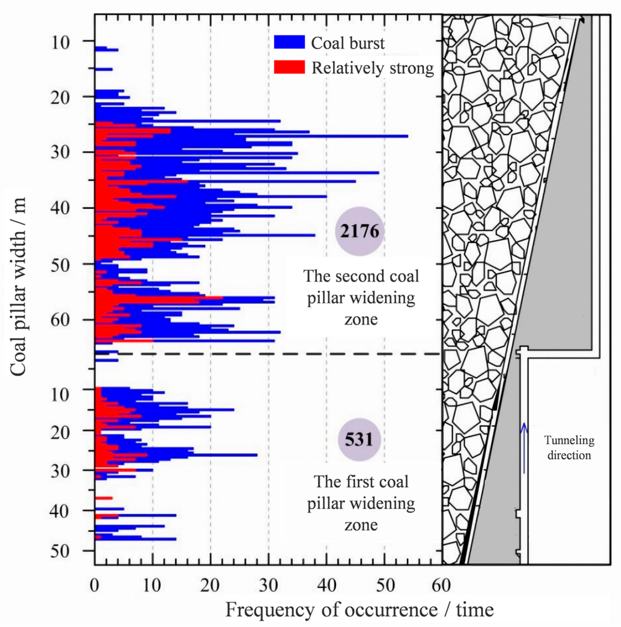
Through field investigation, it was shown that the dynamic phenomenon of mine pressure is obvious and there is a high static load in the 8204-2 island working face of an extra-thick coal seam with a hard roof. In the first widened coal pillar area, the coal burst phenomenon mainly occurred in the range of 8.2 m~33.5 m during roadway excavation. In the second widened coal pillar area, the phenomenon of coal burst was more frequent during roadway excavation. In different regions and ranges, there were noticeable variations in the occurrence of coal burst phenomena and strong coal bursts. The high static load on the island working face is influenced by the specific characteristics of each region.
(2)
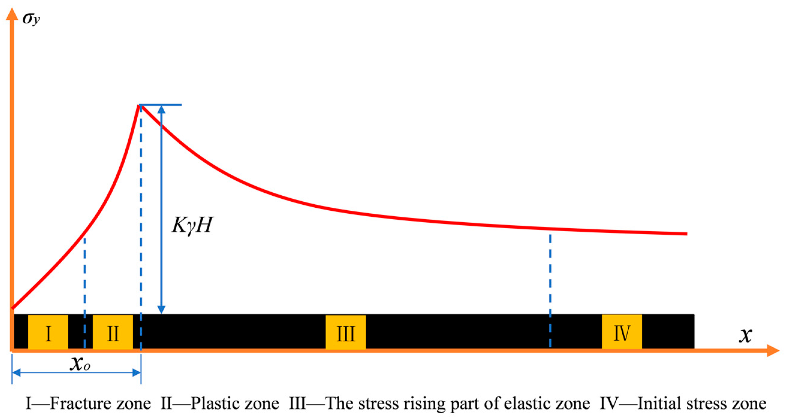
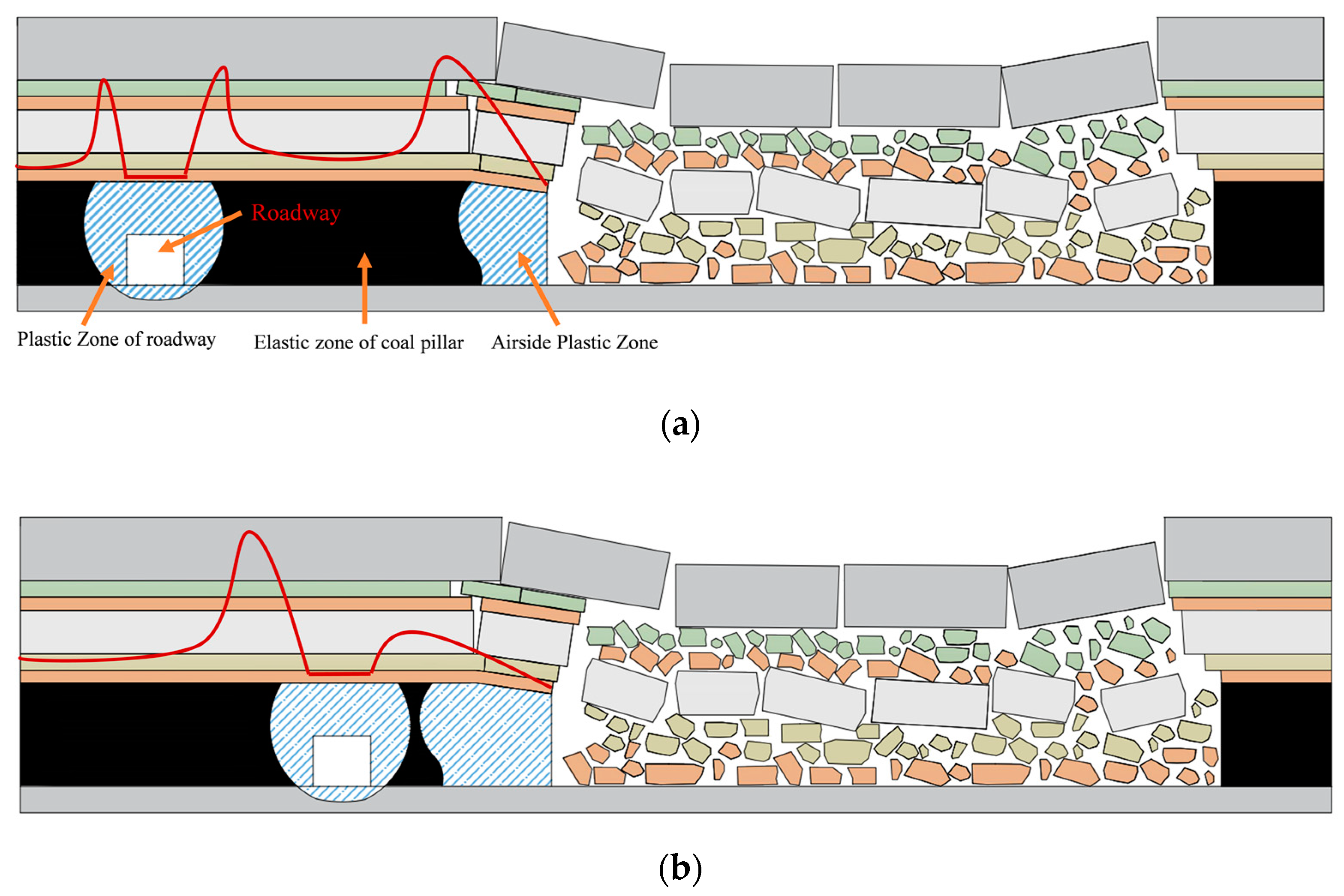
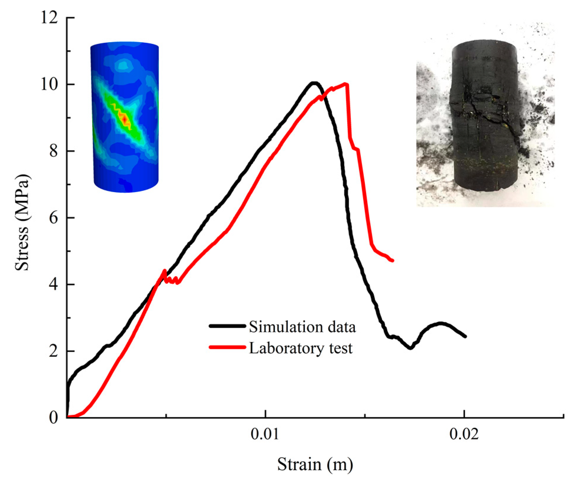
The stress distribution of the island working face was determined to be primarily influenced by five elements through theoretical analysis and mechanical modeling: coal seam thickness, coal pillar width, gob length, buried depth, and working face length. The stress distribution characteristics of the entire island working face, the evolution of the coal pillar’s plastic zone, and the fitting equation for the entity coal’s peak stress were obtained by means of numerical simulation, which also analyzed the stress distribution state of the island working face under various conditions of the five influencing factors.
(3)
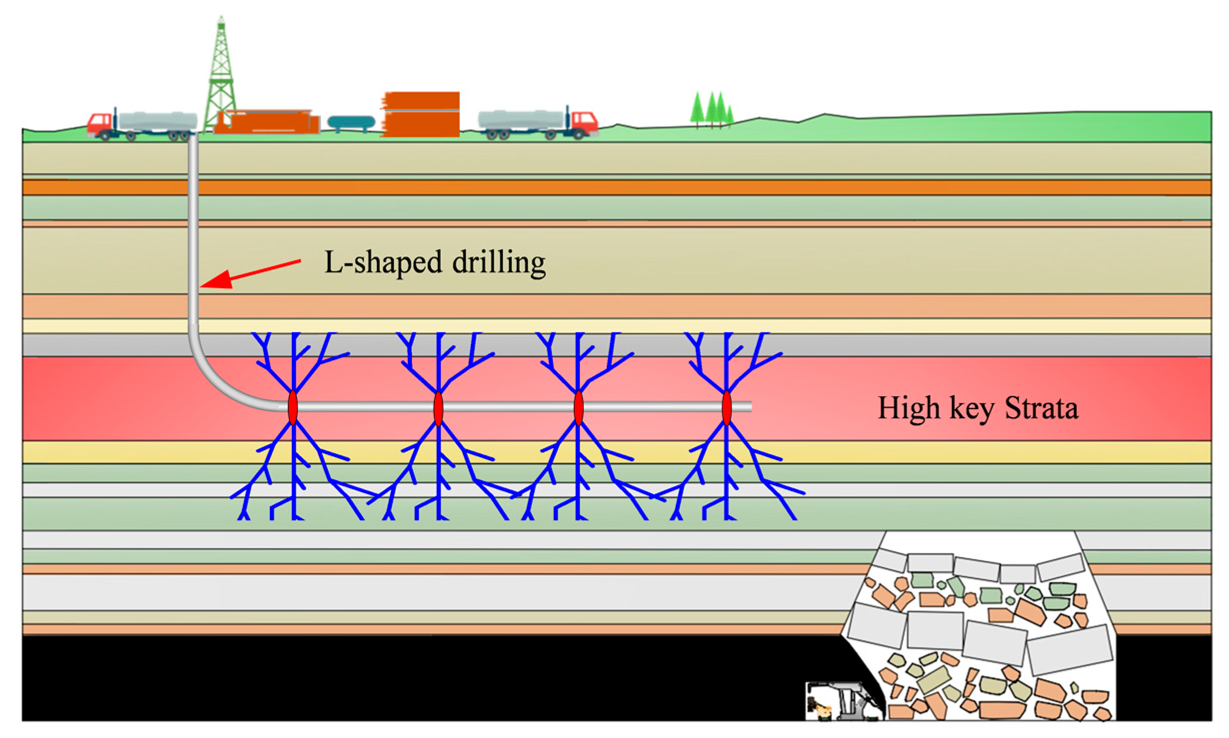
Preventing and controlling rock bursts poses a significant challenge to coal mine safety. Currently, the primary approach to controlling rock bursts is through defensive measures for underground hazard relief. The primary cause of dynamic disasters is the concentration of stress in the coal body and the disruptive effects of a hard roof breaking. The technical means of fracturing the hard roof on the ground have a positive effect by changing the geological dynamic environment and can prevent and control the dynamic disaster from the source. Applying ground fracturing technology, the hard rock strata are weakened and modified, so that the concentrated stress and energy transfer are released to reduce the risk of rock bursts from the source, the impact mine is changed into no impact, and then the underground mining activities can be safely carried out.

Author Contributions

X.D., methodology, software, data curation, and writing—original draft; R.G., methodology, formal analysis, investigation, writing—review and editing; W.G., investigation, data curation; D.B., investigation; X.H., investigation. All authors have read and agreed to the published version of the manuscript.

Funding

This work was supported by the National Natural Science Foundation of China (Grant No. 52274135), Key Research and Development Program of Shanxi Province (Grant No. 202202090301011), Young Elite Scientists Sponsorship Program by the Chinese Association for Science and Technology (Grant No. YESS20220245), and Excellent Youth Training Program of Shanxi Province (Grant No. 202203021224006).

Institutional Review Board Statement

Not applicable.

Informed Consent Statement

Not applicable.

Data Availability Statement

The original contributions presented in the study are included in the article, further inquiries can be directed to the corresponding author.

Conflicts of Interest

The authors declare no conflicts of interest.

References

  1. Cronshaw, I. World Energy Outlook 2014 Projections to 2040: Natural Gas and Coal Trade, and the Role of China. Aust. J. Agric. Resour. Econ. 2015, 59, 571–585. [Google Scholar] [CrossRef]
  2. Wang, G.F.; Xu, Y.X.; Ren, H.W. Intelligent and ecological coal mining as well as clean utilization technology in China: Review and prospects. Int. J. Min. Sci. Technol. 2019, 29, 161–169. [Google Scholar] [CrossRef]
  3. Zhang, S.; Wang, X.F.; Fan, G.W.; Zhang, D.S.; Cui, J.B. Pillar size optimization design of isolated island panel gob-side entry driving in deep inclined coal seam—Case study of Pingmei No. 6 coal seam. J. Geophys. Eng. 2018, 15, 816–828. [Google Scholar] [CrossRef]
  4. Wen, Y.Y.; Cao, A.Y.; Guo, W.H.; Xue, C.C.; Lv, G.W.; Yan, X.L. Strata Movement and Mining-Induced Stress Identification for an isolated Working Face Surrounded by Two Gobs. Energies 2023, 16, 2839. [Google Scholar] [CrossRef]
  5. Lan, T.W.; Liu, Y.H.; Yuan, Y.N.; Liu, H.L.; Liu, H.G.; Zhang, S.F.; Wang, S.X. Mine pressure behavior law of isolated island working face under extremely close gob in shallow coal seam. Sci. Rep. 2023, 13, 20597. [Google Scholar] [CrossRef] [PubMed]
  6. Wang, Y.C.; Chen, P.K.; Wang, S. Study of Overlying Rock Structure and Intensive Pressure Control Technology of Island Longwall Panel in Extra-Thick Coal Seams. Processes 2023, 11, 3083. [Google Scholar] [CrossRef]
  7. Dou, L.M.; He, H. Study of OX-F-T spatial structure evolution of overlying strata in coal mines. Chin. J. Rock Mech. Eng. 2012, 31, 453–460. (In Chinese) [Google Scholar]
  8. Dou, L.M.; He, J.; Cao, A.Y.; Gong, S.Y.; Cai, W. Rock burst prevention methods based on theory of dynamic and static combined load induced in coal mine. J. China Coal Soc. 2015, 40, 1469–1476. (In Chinese) [Google Scholar]
  9. Zhu, S.T.; Jiang, F.X.; Liu, J.H.; Ma, Y.Z.; Meng, X.J.; Zhang, X.F.; Jiang, Y.W.; Qu, X.C.; Wang, B.Q. Types, occurrence mechanism and prevention of overall instability induced rock bursts in China coal mines. J. China Coal Soc. 2020, 45, 3667–3677. (In Chinese) [Google Scholar]
  10. Jiang, Y.D.; Pan, Y.S.; Jiang, F.X.; Dou, L.M.; Ju, Y. State of the art review on mechanism and prevention of coal bumps in China. J. China Coal Soc. 2014, 39, 209–213. (In Chinese) [Google Scholar]
  11. Jiang, Y.D.; Wang, H.W.; Xue, S.; Zhao, Y.X.; Zhu, J.; Pang, X.F. Assessment and mitigation of coal bump risk during extraction of an island longwall panel. Int. J. Coal Geol. 2015, 95, 20–33. (In Chinese) [Google Scholar] [CrossRef]
  12. Zhang, W.L.; Li, C.; Jin, J.X.; Qu, X.C.; Fan, S.; Xin, C.W. A new monitoring-while-drilling method of large diameter drilling in underground coal mine and their application. Measurement 2021, 173, 108840. [Google Scholar] [CrossRef]
  13. Zhang, Z.; Li, Z.; Xu, G.; Gao, X.J.; Liu, Q.J.; Li, Z.J.; Liu, J.C. Lateral abutment pressure distribution and evolution in wide pillars under the first mining effect. Int. J. Min. Sci. Technol. 2023, 33, 309–322. [Google Scholar] [CrossRef]
  14. Li, C.; Xie, H.P.; Gao, M.Z.; Xie, J.; Deng, G.D.; He, Z.Q. Case study on the mining-induced stress evolution of an extra-thick coal seam under hard roof conditions. Energy Sci. Eng. 2020, 8, 309–322. [Google Scholar] [CrossRef]
  15. Lehtonen, A.; Cosgrove, J.W.; Hudson, J.A.; Johansson, E. An examination of in situ rock stress estimation using the Kaiser effect. Eng. Geol. 2012, 124, 24–37. [Google Scholar] [CrossRef]
  16. Bai, X.; Zhang, D.M.; Wang, H.; Li, S.J.; Rao, Z. A novel in situ stress measurement method based on acoustic emission Kaiser effect: A theoretical and experimental study. R. Soc. Open Sci. 2018, 5, 181263. [Google Scholar] [CrossRef] [PubMed]
  17. Li, X.L.; Wang, E.Y.; Li, Z.H.; Liu, Z.T.; Song, D.Z.; Qiu, L.M. Rock Burst Monitoring by Integrated Microseismic and Electromagnetic Radiation Methods. Rock Mech. Rock Eng. 2016, 49, 4393–4406. [Google Scholar] [CrossRef]
  18. Lou, Q.; Song, D.Z.; He, X.Q.; Li, Z.L.; Qiu, L.M.; Wei, M.H.; He, S.Q. Correlations between acoustic and electromagnetic emissions and stress drop induced by burst-prone coal and rock fracture. Saf. Sci. 2019, 115, 310–319. (In Chinese) [Google Scholar] [CrossRef]
  19. Jiang, B.Y.; Wang, L.G.; Lu, Y.L.; Wang, C.Q.; Ma, D. Combined early warning method for rockburst in a Deep Island, fully mechanized caving face. Arab. J. Geosci. 2016, 9, 743. [Google Scholar] [CrossRef]
  20. He, J.; Dou, L.M.; Gong, S.Y.; Li, J.; Ma, Z.Q. Rock burst assessment and prediction by dynamic and static stress analysis based on micro-seismic monitoring. Int. J. Rock Mech. Min. Sci. 2017, 93, 46–53. [Google Scholar] [CrossRef]
  21. Ma, K.; Wang, H.Y.; Liao, Z.Y.; Peng, Y.L.; Wang, K.K. Precursor of microseismic energy and stress evolution induced by rockburst in coal mining: A case study from Xiashijie, Shannxi, China. Geomech. Geophys. Geo-Energy Geo-Resour. 2022, 8, 134. [Google Scholar] [CrossRef]
  22. Ge, M.C. Efficient mine microseismic monitoring. Int. J. Coal Geol. 2005, 64, 44–56. [Google Scholar] [CrossRef]
  23. Shen, B.; King, A.; Guo, H. Displacement, stress and seismicity in roadway roofs during mining-induced failure. Int. J. Rock Mech. Min. Sci. 2008, 45, 672–688. [Google Scholar] [CrossRef]
  24. Yu, B.; Zhang, Z.Y.; Kuang, T.J.; Liu, J.R. Stress Changes and Deformation Monitoring of Longwall Coal Pillars Located in Weak Ground. Rock Mech. Rock Eng. 2016, 49, 3293–3305. [Google Scholar] [CrossRef]
  25. Jia, C.Y.; Wang, H.L.; Sun, X.Z.; Yu, X.B.; Luan, H.J. Study on rockburst prevention technology of isolated working face with thick-hard roof. Geomech. Eng. 2020, 20, 447–459. [Google Scholar]
  26. Zhu, G.A.; Dou, L.M.; Cao, A.Y.; Cai, W.; Wang, C.B.; Liu, Z.G.; Li, J. Assessment and analysis of strata movement with special reference to rock burst mechanism in island longwall panel. J. Cent. South Univ. 2017, 24, 2951–2960. [Google Scholar] [CrossRef]
  27. Liu, G.J.; Mu, Z.L.; Chen, J.J.; Yang, J.; Cao, J.L. Rock burst risk in an island longwall coal face by stress field. Geosci. J. 2018, 22, 609–622. [Google Scholar] [CrossRef]
  28. Xu, Q.Y.; Bai, J.B.; Yan, S.; Wang, R.; Wu, S.X. Numerical Study on Soft Coal Pillar Stability in an Island Longwall Panel. Adv. Civ. Eng. 2021, 2021, 8831778. [Google Scholar] [CrossRef]
  29. Liu, C.Y.; Huang, B.X.; Meng, X.J.; Yang, P.J.; Chen, L.G. Research on abutment pressure distribution law of overlength isolated fully-mechanized top coal caving face. Chinese J. Rock Mech. Eng. 2007, 26, 2761–2766. (In Chinese) [Google Scholar]
  30. Wang, H.W.; Jiang, Y.D.; Zhao, Y.X.; Liu, S.; Gao, R.J. Investigation on mechanism of energy explosion during extraction of island longwall panel. Chinese J. Rock Mech. Eng. 2013, 22, 2250–2257. (In Chinese) [Google Scholar]
  31. Dou, L.M.; Jiang, Y.D.; Cao, A.Y.; Liu, H.S.; Gong, S.Y.; Cai, W.; Zhu, G.A. Monitoring and pre-warning of rockburst hazard with technology of stress field and wave field in underground coalmines. J. Rock Mech. Eng. 2017, 36, 803–811. (In Chinese) [Google Scholar]
  32. Dou, L.M.; Bai, J.Z.; Li, X.W.; He, H. Study on prevention and control technology of rockburst disaster based on theory of dynamic and static combined load. Coal Sci. Technol. 2018, 46, 1–8. (In Chinese) [Google Scholar]
  33. Cao, A.Y.; Zhu, L.L.; Li, F.C.; Dou, L.M.; Zhao, Y.L.; Zhang, Z.L. Characteristics of T-type overburden structure and tremor activity in isolated face mining under thick-hard strata. J. China Coal Soc. 2014, 39, 328–335. (In Chinese) [Google Scholar]
  34. Min, T.; Bu, Q.W.; Fu, B.J.; Wang, Y. Mechanical Analysis of Mining Stress Transfer on isolated Island Face in Extra-Thick Fully Mechanized Top-Coal Caving Mining. Geofluids 2020, 2020, 8834321. [Google Scholar]
  35. Yu, B.; Zhu, W.B.; Gao, R.; Liu, J.R. Strata structure and its effect mechanism of large space stope for fully-mechanized sublevel caving mining of extremely thick coal seam. J. China Coal Soc. 2016, 41, 571–580. (In Chinese) [Google Scholar]
  36. Qian, M.G.; Shi, P.W.; Xu, J.L. Mining Pressure and Strata Control, 2nd ed.; China University of Mining and Technology Press: Xuzhou, China, 2010. [Google Scholar]
  37. Xu, Y.X.; Li, H.M.; Wang, K.L.; Yuan, R.F. Study on Lateral Support Pressure Distribution of Fully—Mechanized Coal Mining Face in Ultra Thick Seam. Coal Sci. Technol. 2014, 42, 26–28. (In Chinese) [Google Scholar]
  38. Guan, L.G.; Xu, D.; Chen, Z.; Liu, C.; Gao, M.S.; Zhang, D.X. Study on Optimization of Section Coal Pillar Size in Large Mining Height and High Strength Mining Face. Coal Technol. 2022, 41, 29–34. (In Chinese) [Google Scholar]
  39. He, W.R.; He, F.L.; Zhao, Y.Q. Field and simulation study of the rational coal pillar width in extra-thick coal seams. Energy Sci. Eng. 2020, 8, 627–646. [Google Scholar] [CrossRef]
  40. Yu, B.; Gao, R.; Xia, B.W.; Kuang, T.J. Ground fracturing technology and application of hard roof in large space. J. China Coal Soc. 2021, 46, 800–811. (In Chinese) [Google Scholar]
  41. Gao, R. The Mechanism of Ground Pressure Induced by the Breakage of Far-Field Hard Strata and the Control Technology of Ground Fracturing. Ph.D. Thesis, China University of Mining and Technology, Beijing, China, 2018. (In Chinese). [Google Scholar]
  42. Wang, S.W.; Zhi, B.Y.; Du, T.T.; Yang, G.Y.; Lu, C.; Xia, Y.X. Ground fracturing pre-control technology for potential mine seismic risk of thick and hard roof. Coal Sci. Technol. 2023, 51, 1–11. (In Chinese) [Google Scholar]
Figure 1. Deformation characteristics of roadway.
Applsci 14 01961 g001
Figure 2. Location of the Tashan coal mine.
Applsci 14 01961 g002
Figure 3. Layout of the working face.
Applsci 14 01961 g003
Figure 4. Strong mine pressure behavior of 5204-2 roadway.
Applsci 14 01961 g004
Figure 5. Relationship between coal burst frequency and coal pillar width.
Applsci 14 01961 g005
Figure 6. Structural characteristics of overlying strata of isolated island coal.
Applsci 14 01961 g006
Figure 7. Elastic-plastic deformation zone and vertical stress distribution of coal seam.
Applsci 14 01961 g007
Figure 8. (a) Stress distribution and failure feature of large coal pillar roadway; (b) stress distribution and failure feature of small coal pillar roadway.
Applsci 14 01961 g008
Figure 9. Numerical simulation model.
Applsci 14 01961 g009
Figure 10. Parameter calibration of coal seam.
Applsci 14 01961 g010
Figure 11. Simulation and calculation matching results.
Applsci 14 01961 g011
Figure 12. (a) Stress distribution features of island working face under different buried depths; (b) the stress variation law and plastic zone evolution characteristics of coal pillar under different buried depths; (c) fitting curve of peak stress of entity coal and buried depth.
Applsci 14 01961 g012
Figure 13. (a) Stress distribution features of island working face under different gob lengths; (b) the stress variation law and plastic zone evolution characteristics of coal pillars under different gob lengths; (c) fitting curve of peak stress of entity coal and gob length.
Applsci 14 01961 g013
Figure 14. (a) Stress distribution features of island working face under different working face; (b) the stress variation law and plastic zone evolution characteristics of coal pillar under different working faces; (c) fitting curve of peak stress of entity coal and working face length.
Applsci 14 01961 g014
Figure 15. (a) Stress distribution features of island working face under different coal seam thicknesses; (b) the stress variation law and plastic zone evolution characteristics of coal pillar under different coal seam thicknesses; (c) fitting curve of peak stress of entity coal and coal seam thickness.
Applsci 14 01961 g015
Figure 16. (a) Stress distribution features of island working face under different coal pillar widths; (b) the stress variation law and plastic zone evolution characteristics of coal pillars under different coal pillar widths; (c) fitting curve of peak stress of entity coal and coal pillar width.
Applsci 14 01961 g016
Figure 17. Principle of dynamic and static combined load inducing rock burst.
Applsci 14 01961 g017
Figure 18. Schematic diagram of ground fracturing to prevent rock burst.
Applsci 14 01961 g018
Table 1. Physical mechanics parameters of coal rock.
LithologyElastic Modulus
(GPa)
Poisson RatioFriction Angle
(°)
Tensile Strength
(MPa)
Cohesion
(MPa)
Medium grained sandstone17.50.29221.15.4
Fine-grained sandstone28.50.23255.96.2
Siltstone19.30.27232.46.1
Sandy mudstone10.50.27222.95.3
Grit stone24.60.26223.65.6
Coal seam7.50.33201.14
Mudstone80.32212.24.2
Kaolin rock170.22223.24.1
Table 2. Physical mechanical parameters of gob.
Bulk Modulus
(MPa)
Shear Modulus
(MPa)
Density
(kg/m3)
Tensile Strength
(MPa)
Friction Angle
(°)
5.351.081100028
Table 3. Experimental scheme.
SchemeBuried Depth
H/m
Gob Length
L/m
Working Face Length
D/m
Coal Seam Thickness
M/m
Coal Pillar Width
B/m
1300/400/500/6004003016200
2200100/150/200/2503016200
3200400100/150/200/25016200
4200400308/12/16/20200
5200400301610/20/30/40
Table 4. Detailed parameters.
OriginQuadratic SumDfMean Square
Regression18,083.56163013.927
Residual14.653101.465
Uncorrected total18,098.21416
Corrected total603.95815
R2 = 1 − (residual sum of squares)/(corrected sum of squares) = 0.976
Disclaimer/Publisher’s Note: The statements, opinions and data contained in all publications are solely those of the individual author(s) and contributor(s) and not of MDPI and/or the editor(s). MDPI and/or the editor(s) disclaim responsibility for any injury to people or property resulting from any ideas, methods, instructions or products referred to in the content.

