Article

Computational Analysis for the Evaluation of Fire Resistance in Constructive Wooden Elements with Protection

Mechanical Engineering Department, School of Engineering, Polytechnic Institute of Porto, Rua Dr. António Bernardino de Almeida, 431, 4200-072 Porto, Portugal
*
Author to whom correspondence should be addressed.
Appl. Sci. 2024, 14(4), 1477; https://doi.org/10.3390/app14041477
Submission received: 22 November 2023 / Revised: 24 January 2024 / Accepted: 9 February 2024 / Published: 11 February 2024

Abstract

:
Wood is a material whose properties vary depending on different conditions, being particularly vulnerable to changes induced by high temperatures. When exposed to a fire situation, the wood properties suffer degradation, causing a char layer formation. Despite ensuring the protection of the inner core of the wood, the char layer reduces its resistant section. The evaluation of wood behavior under fire conditions is possible through experimental tests, simplified analytical models, and numerical models. To overcome difficulties in the development of experimental tests and in the approximations made to analytical methods, numerical models allow the evaluation of the fire resistance in a parametric way. First, this study will present a numerical model validated with an experimental test, using the finite element method. The validation of the results is based on the evolution of the temperature field, the char layer formation on the wooden elements, and its residual section, as well as the application of the thermal insulation criterion. The second part of the study evaluates the influence of geometric parameters, associated with different wooden constructive models with gypsum board exposed to fire. Different numerical tests are presented to evaluate the thermal and transient analysis of different wooden constructive elements with gypsum board. This type of constructive element presents cavities, making the numerical analysis in the study complex when approaching real models. The methodology applied allowed us to conclude that, at the same time, a smaller distance between wooden centers, a greater dimension of the wooden beam in height and width, as well as a greater thickness of gypsum board guarantee a better performance of the constructive wooden model.

1. Introduction

In the literature, there are some authors who have dedicated themselves to investigating analytical and empirical models in wood in fire situations and carrying out experimental tests.
The heat flow in wood leads to a thermochemical decomposition (pyrolysis) which results in the char layer formation, associated with by mass loss. In wood elements exposed to fire, the char layer occurs and increases in depth with heat progression. According to EC5-1-2, (CEN EN1995-1-2, 2004) [1], the isotherm of the char layer corresponds to 300 °C. All these phenomena were verified by different research ventures and have been extensively investigated to ensure their structural safety and integrity. Between others, several researchers have presented experimental and empirical methods to estimate wood degradation due to fire conditions, (White and Nordheim, 1992; Mangs and Hostikka, 2011; Yang et al., 2019; Rogaume, 2019; Hehnen et al., 2020), [2,3,4,5,6].
In 1998, H. Takeda and J. R. Mehaffey [7] developed different tests on wooden elements and obtained results on temperature over time and char layer formation to verify the fire resistance in all tested models. Furthermore, these authors developed a two-dimensional computational model called WALL2D to predict heat transfer in protected wooden beams and concluded that it agrees with the results of small and full-scale fire resistance tests [7,8].
In 2003, Andrea Frangi and Fontana [9] carried out research to study the fire behavior of wooden slabs and beams. The experimental tests consisted of a sequence of series carried out following the parameters of ISO 834 [10].
In another article, in 2009, Andrea Frangi et al. [11] conducted a study to evaluate the fire behavior of CLT panels when subjected to standard fire conditions and compare it with the results obtained for homogeneous wooden elements. The tests were carried out in the laboratory, on a reduced scale. The results obtained allowed the researchers to conclude that the fire behavior of CLT panels is highly influenced by the type of adhesive used to join them.
Still in 2009, Te-Hsin Yang et al. [12] carried out an experimental analysis to determine the depth of the char layer, the charring rate, and the release of heat energy from Glulam panels GLT when subjected to fire exposure, according to the standard fire curve. Through this evaluation, the researchers concluded that the charring rates obtained in most types of glulam were those defined in EC5-1-2, EN 1995-1-2 (2003) [1]. Additionally, they found that the charring rate decreases with the increasing density of GLT.
Andrea Frangi et al. [13,14], in 2010, carried out an experimental study to analyze the fire behavior of wooden constructive elements, for use on walls or floors, protected with plasterboard in standard fire conditions. The main objective was to verify the fire resistance criteria of integrity and thermal insulation. To this end, fire exposure tests were conducted on a reduced scale of elements with different properties, in terms of material, thickness, position, and number of protective coatings. Therefore, researchers [13,14] submitted different solutions to verify the impact of changes in the materials on fire.
In 2019, Alastair I. Bartlett et al. [15] published a study where they presented a set of experimentally obtained factors that affect the average charring rate of wooden constructive elements exposed to fire. Thus, the authors concluded that the main properties of wood that affect its fire resistance are density and moisture content, causing an increase in the charring rate of up to 18%. Still, the main factor that influences the decrease in fire resistance is the heat flow induced by the fire temperature. On the other hand, it was found that the placement of a fire-resistant protective coating reduces the charring rate and delays the collapse of the element by approximately 80% [15].
In another study, in 2019, R. Fahrni et al. [16] carried out an experimental analysis that consisted of evaluating the fire resistance of glulam structural beams when subjected to four-point bending, under standard fire conditions. Before the study, the properties of the six constructive elements of GL24h and GL36h were analyzed, namely the density, as well as the verification of surface defects that induce an increase in the carbonization rate. The objective was to determine the depth of the char layer and compare it with the calculation method presented by EC5-1-2, EN 1995-1-2 (2003) [1].
Among others, some authors have been dedicated to using computational analysis to investigate the behavior of wooden models.
Massimo Fragiacomo et al. [17], in 2013, published a numerical model developed to predict the fire resistance of wooden elements. The computational method consisted of a double evaluation using the process defined by the code. The first step consisted of an evolutionary thermal analysis over time of the element when exposed to fire and the second a structural analysis considering a constant load. Additionally, they carried out experimental tests to compare results.
In 2018, Van Diem Thi et al. [18] presented a numerical methodology intending to simulate fire resistance at the level of integrity of wooden elements exposed to fire, on a real scale. Compared with work developed by other researchers, the main attribute of the proposed model is the fact that it predicts the degradation of a transverse wooden profile applied in the central area of the vertical profiles.
In 2020, Piloto and Fonseca [19], also co-authors of this work, proposed a numerical model to evaluate the fire resistance of a constructive solution, consisting of a plasterboard plate on each side and longitudinal wooden profiles. The methodology developed allowed the evaluation of temperature at different points and the evolution of the char layer over time. The proposed numerical model was validated with one experimental test (Test 6) from Takeda and Mehaffey [7]. The researchers [19] concluded that increasing the section of the wooden profiles does not cause a significant increase in fire resistance in terms of the thermal insulation criterion. However, they found that this increase in section gives the construction element a significant increase in load capacity, resulting from the increase in residual section [19].
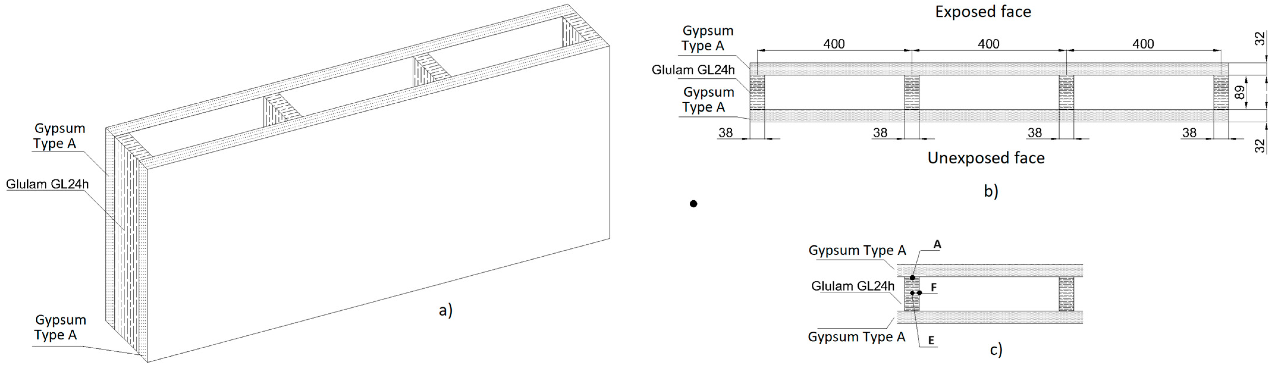
In this study, the constructive wooden elements are protected with gypsum board, such as inner partitions, and inner boards of outer walls and ceilings, for example. These elements are submitted to certification, which is the fire resistance classification of materials according to their integrity and insulation [1,20,21]. The constructive wooden components are unloaded elements with one side exposed to fire, such as inner wood-stud walls, combined with solid wood beams and gypsum board, and forming internal air cavities. The fire resistance rating is defined following the safety laws against fire in buildings RT SCIE (DL220 of 2008) [22]. Fire resistance is a measure for a specified time under fire conditions of a standard heat, in which the constructive elements have a performance to develop the purposes for which are designed.
The main objective of this study was to simulate the fire resistance in a standard test method using an experimental model which allows for calibration of the developed numerical model. The temperature fields numerically obtained in the model were calibrated at different points previously tested by the referenced authors [7]. The fire resistance calculation can be carried out using experimental and numerical tests, as well as through analytical and simplified models. After the experimental validation of the newly presented numerical model, different new parametric models were developed that could be applied to construction. Different results were obtained, the temperature field, the residual wood cross-sections for different time fire exposure instants, and the fire resistance calculated with the thermal insulation criterion. The results show consistency of the analysis and can be used as a good approximation to real situations.

2. Experimental Validation

Takeda and Mehaffey [7] presented the results of several experimental tests in different wooden constructive models, presenting the properties of wood and gypsum board materials used.

2.1. Experimental Test 4

The experimental tests carried out by the authors [7] differed in several parameters, such as test scale, model constitution, type of materials and dimensions. Thus, of the six experimental tests carried out, four were carried out on a reduced scale and two on a full scale. All models consider a constructive solution in wood with gypsum board. The gypsum board used by Takeda and Mehaffey [7] were types C and X, with a density at room temperature of 732 and 648 kg/m3, respectively. Additionally, it was standardized, in all models, that gypsum board type C had a thickness of 12.7 mm and type X had a thickness of 15.9 mm. Regarding wood material, the authors do not define the type of wood considered. However, they generally present two types of wood “SPF” and “Douglas fir”, with a density at room temperature of approximately 480 and 550 kg/m3, respectively.
According to this, to compare the numerical solution proposed in this work, Test 4 [7] was used with the dimensions represented in Figure 1. The wooden material was considered in glulam GL24H and the gypsum board as type A with a density equal to 648 kg/m3, both with approximation of the values to the referenced Test 4 [7]. Previously in other publication [19] similar properties were considered in the numerical model validated with Test 6 from Takeda and Mehaffey [7].
The temperature fields obtained at different points measured by the authors [7] were analyzed, with a special interest in the interface between the wood and the gypsum board (point A), another point between the air cavity and the wood element (point F), and another point in the middle of the wooden beam (point E). Simultaneously, the residual wood cross-sections will be compared for periods equal to 90, 100, and 110 min. Finally, the thermal insulation criterion, defined by the standard EN 1363-1:2020 [20], was used to measure and compare the fire resistance between the experimental and numerical models.

2.2. Numerical Model

When developing the numerical models, different hypotheses were considered about the air cavities of the constructive model: M1—model with air mesh (considered as a solid model that allows heat conduction inside the cavity); M2—model with radiation effect due to the introduction of a new finite element SURF151, inside the cavity; M3—model with radiation and convection boundaries in the cavity, but introducing a test curve Tf-Test 4, representative of the temperature evolution inside the cavity; and M4—model with radiation effect with the finite element SURF151 and the application of convection with LINK34 element. In the other parts of the constructive model, the two-dimensional (2D) element PLANE55 was used. All these models are shown in Figure 2 representing the developed meshes and their boundary conditions.
The finite elements used were:
  • PLANE55—2D Thermal Solid Element—can be used as a plane element for thermal conduction capacity. The element has four nodes with a single degree of freedom, temperature, at each node. The element is appropriate for a 2D thermal analysis in steady-state or transient [23,24].
  • SURF151—Surface Thermal Effect—used for various load and surface effect applications. It may be overlaid on the face of any 2D thermal solid element. It allows the radiation between the internal surfaces of the cavity and any point inside it. The SURF151 element consists of two nodes, associated with an extra node, located inside the cavity.
  • LINK34—Convection Link Element—is a uniaxial element with the ability to conduct heat between its nodes. The element has a single degree of freedom, temperature, at each node point. The convection element is valid for 2D or 3D thermal analysis in steady-state or transient. The element is defined by two nodes, a node on the surface and another inside the cavity, to represent a convection surface area [23].
To elaborate the finite element mesh, perfect contact between all the materials was assumed, to allow the thermal energy conduction between them, with the element edge dimension equal to 10 mm.
The thermal characteristics associated with wood GL24H, the gypsum board type A and air are following references [13,25,26], to approximate the materials involved in Test 4 [7]. On the surface exposed to fire, the boundary conditions are radiation and convection, with the effect of increasing temperature through the introduction of the experimental fire curve Tf. The initial conditions of the model correspond to an ambient temperature of 20 °C. The relative emissivity properties of the wood material were 0.8 and 0.85 for gypsum board. On the unexposed face, only the convection was considered. At the lateral edges of the numerical model, an adiabatic condition was assumed, with no heat exchange between these zones. All these conditions comply with EC1-1-2 [20]. To satisfy the non-linear conditions of the problem, the program uses the Newton–Raphson iterative method, with a convergence criterion based on the heat flux with a tolerance equal to 0.9. The total time of each simulation corresponds to a fire exposure of 120 min.

2.3. Comparison of Temperature Field

Based on the analysis carried out on each numerical model, the results of the temperature evolution at the three nodal points are presented. Figure 3 represents the numerical results obtained and compared with Test 4 in the points (A, E, F). All graphics represent the real fire curve used in the laboratory Tf_test4. In the M3 model, the heating curve considered in the cavity was the F_Test4 curve obtained experimentally.
According to the results, curve A is the one with the highest temperature field because it is located between the gypsum board and the wood interface. Curve E is the one with the lowest temperature profile because it is located inside the wood component.
Regarding the comparison of results between experimental and numerical tests, model M1 presents a great variation. M2 presents some similarities to the experimental test. M4 is the model that presents behavior closest to the experimental one, approaching the results obtained with M3, and both can validate the temperature results of Test 4 [1]. According to the results shown in Figure 3, a quantitative observation was obtained between models M3 and M4.
Table 1 presents the amount of data on temperatures registered (n), the mean values of temperatures (M), the standard deviation (SD), and the standard error of the mean (SEM) for the models M3 and M4. The SD describes the variability between data of temperature; the SEM estimates the precision and uncertainty of how the study data represents the original population.
The high value of SD allows us to form a conclusion on the high variability of the temperature values during all exposure fire, which was expected. The SEM indicates that the lower values are obtained in model M4, which permits to identity of model M4 as the chosen.

2.4. Comparison of Residual Cross-Section

In the following step, models M2, M3, and M4 were also analyzed according to the evolution of the char layer over time for the instants of 90, 100, 110, and 120 min. The wood profile used to analyze the char layer was in a cross-section of the central wooden beam, to obtain results for the most critical region. The limit temperature considered for the formation of the char layer, imposed by the authors [7], was 288 °C.
To evaluate the char layer and compare their proximity with the results obtained experimentally, the percentage of the residual wood cross-sections was determined, as shown in Table 2. Simultaneously, the relative error was calculated, regarding Test 4, and presented in Table 2.
Based on the representation of the char-layer obtained by the experimental tests from the authors [7], the ImageJ® 1.52a software was used to determine the residual wood cross-section. This software relates the pixels of a given image to the dimensions of the element and delimits sections by color, thus, allowing the charred area to be obtained. With this, it was possible, considering the total area of the amount of wood and the charred area, to calculate the residual wood cross-section, R, by applying Equation (1).
R = A r e a A c h a r r e d A r e a × 100
Considering the results obtained in Table 2, it is concluded that the model developed with the effect of radiation and convection in the cavities (M4) presents the closest and most favorable results to Test 4. For the instants 90, 100, and 110 min, in M4, the relative error was smaller, and the values were closer to Test 4 when compared to the other models, except for 120 min.

2.5. Comparison of Fire Resistance

To obtain fire resistance, it is necessary to apply the thermal insulation criterion, defined by the standard EN 1363-1:2020 [20]. The fire resistance by this criterion is defined by the shortest time step, on the unexposed face, based on the maximum temperature Tmáx, that is, 180 °C above the initial temperature T0 of 20 °C, or by the mean surface temperature Tméd, 140 °C above the initial temperature, Equations (2) and (3), respectively.
T m á x = T 0 + 180
T m é d = T 0 + 140
According to the standard EN 1363-1:2020 [20], as soon as the surface not exposed to fire reaches a temperature higher than the maximum point temperature or the average allowable temperature, the insulation criterion is no longer verified.
To analyze the temperature evolution, different nodal points were defined on the model surface not exposed to fire. For this study, only the model M4 was considered, because it presented the best approximation to the experimental test. Additionally, to reach the limit temperatures imposed by the thermal insulation criterion according to EN 1363-1:2020 [20], another numerical simulation was carried out considering the temperature evolution equivalent to 240 min of fire exposure.
The average temperature on the surface not exposed to fire and on the node where the maximum temperature occurs was verified. It was concluded that the fire resistance imposed by the thermal insulation criterion is approximately equal to 216 min.
Analyzing the results obtained by Takeda and Mehaffey [7] for Test 4, and based on the computational model, the authors obtained a fire resistance of approximately equal to 226 min. With this, it is concluded that the results obtained for the developed M4 model are close to the results obtained by the researchers, thus, validating the numerical model.

2.6. The Chosen Numerical Model M4

According to the previous results, Figure 4 represents the chosen numerical model M4, which will be used in the next study in the new numerical parametric models.
Figure 4 shows the mesh with the used finite elements. The SURF151 and LINK34 elements allow the application of thermal boundaries, by overlapping the 2D PLANE55 element. When using surface effect elements with the radiation option for radiating between a surface and a point, the form factor between a surface and the point can be specified as a real constant or can be calculated from the basic element orientation and the extra node location.

3. New Numerical Parametric Models

This chapter consists of computational analysis to evaluate the fire resistance of wooden support elements. Based on the previous validation of the numerical model M4, it becomes possible to study the fire behavior, in different parametric models, considering the same assumptions.
In this way, the variation of geometric parameters, such as the distance between the centers, the height, and width of the wooden beams, as well as the thickness of the gypsum board, allows determining the influence of each variable. Therefore, the present study focuses on determining the temperature range at the control points of the different parametric models, the char layer in the wooden beams, the calculation of the respective residual cross-section, and the fire resistance of the models under analysis, based on the application of the thermal insulation criterion, according to EN 1363-1:2020 [20].
The work is, thus, subdivided into four iterative studies, each evaluating the influence of geometric parameters. The first study consists of varying the distance between the centers of the wooden beams (D), the second on changing the height (W), the third affected the width of the beams (H) and, finally, the fourth evaluated the impact of gypsum board thickness (Tg).
The typical constructive model, with the identification of geometric parameters, is represented in Figure 5. Control points A, E, and F, as well as the 13 nodes located on the surface not exposed to fire to allow the calculation of the thermal insulation criterion, are represented in Figure 5.
Regarding the studies, an iterative and sequential methodology was adopted, with each study consisting of three geometric parameter variations (D, H, W, and Tg), as represented in Table 3, which consists of determining the value relating to the geometric parameter that allows obtaining better performance, that is, greater fire resistance.
The study consists of the development of nine computational analyses using the finite element program ANSYS® 2022R2. From the study of the distance between centers (D), one of the parametric models is repeated in the following study, depending on the best performance. Regarding materials, the use of glued laminated wood GL32h and gypsum board type F was considered, which have the best characteristics for obtaining the greatest fire resistance. In each numerical model different results were obtained, the temperature field at control points A, E, and F, the char layer of the wooden beams and respective residual cross-section, and the fire resistance, through the application of the criterion thermal insulation, by EN 1363-1:2020 [20].

3.1. The Temperature Field

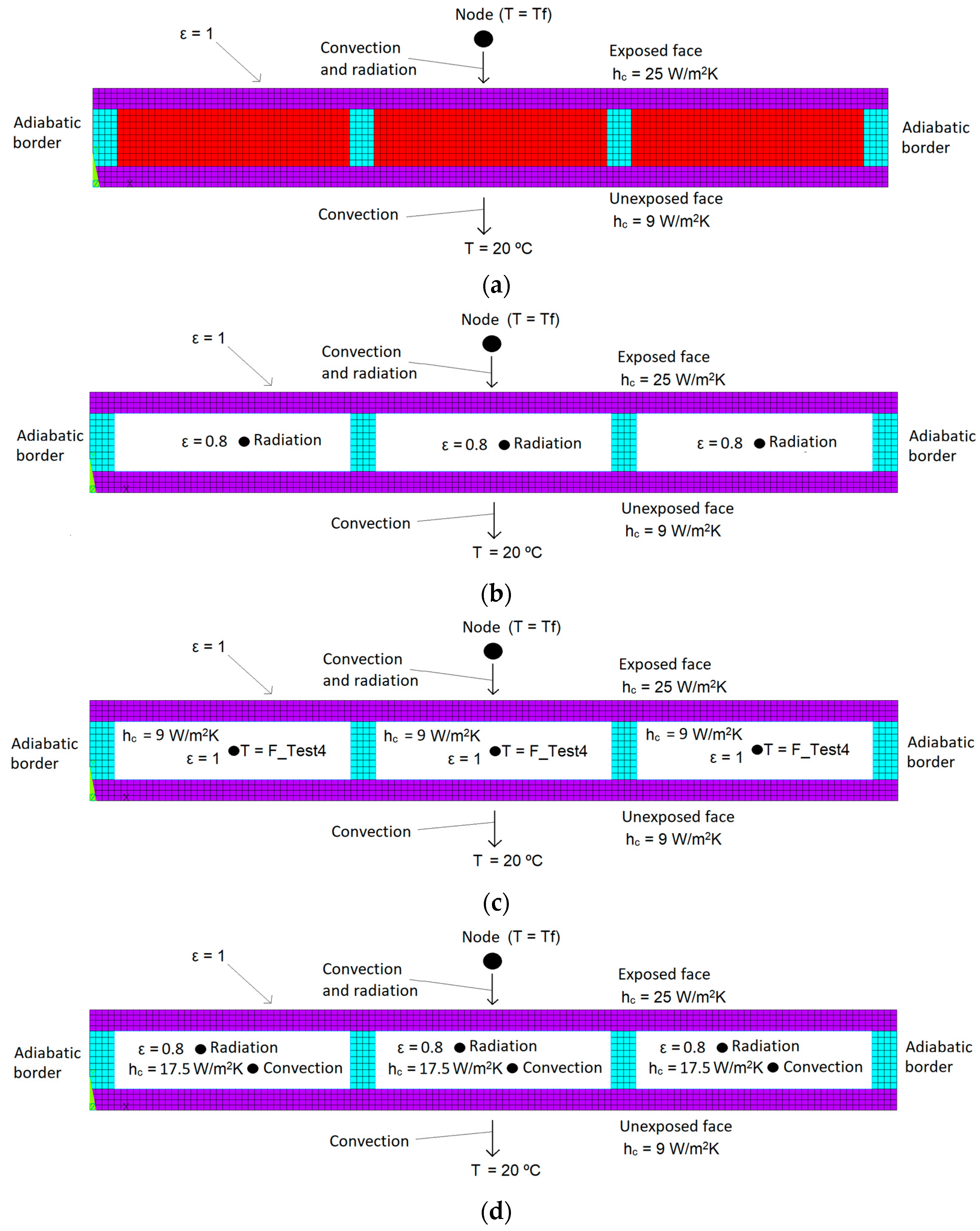
The new parametric models were evaluated under the same conditions as the transient thermal analysis, with the same defined finite elements, type of mesh, and identical boundary conditions. Regarding the boundary conditions of the parametric models, these were like those admitted in the M4 model, referred to in the experimental validation. However, the new parametric models under study are subject to the standard fire curve, defined following ISO 834-1:199 [10]. The boundary conditions applied in the new parametric models are represented in Figure 6.
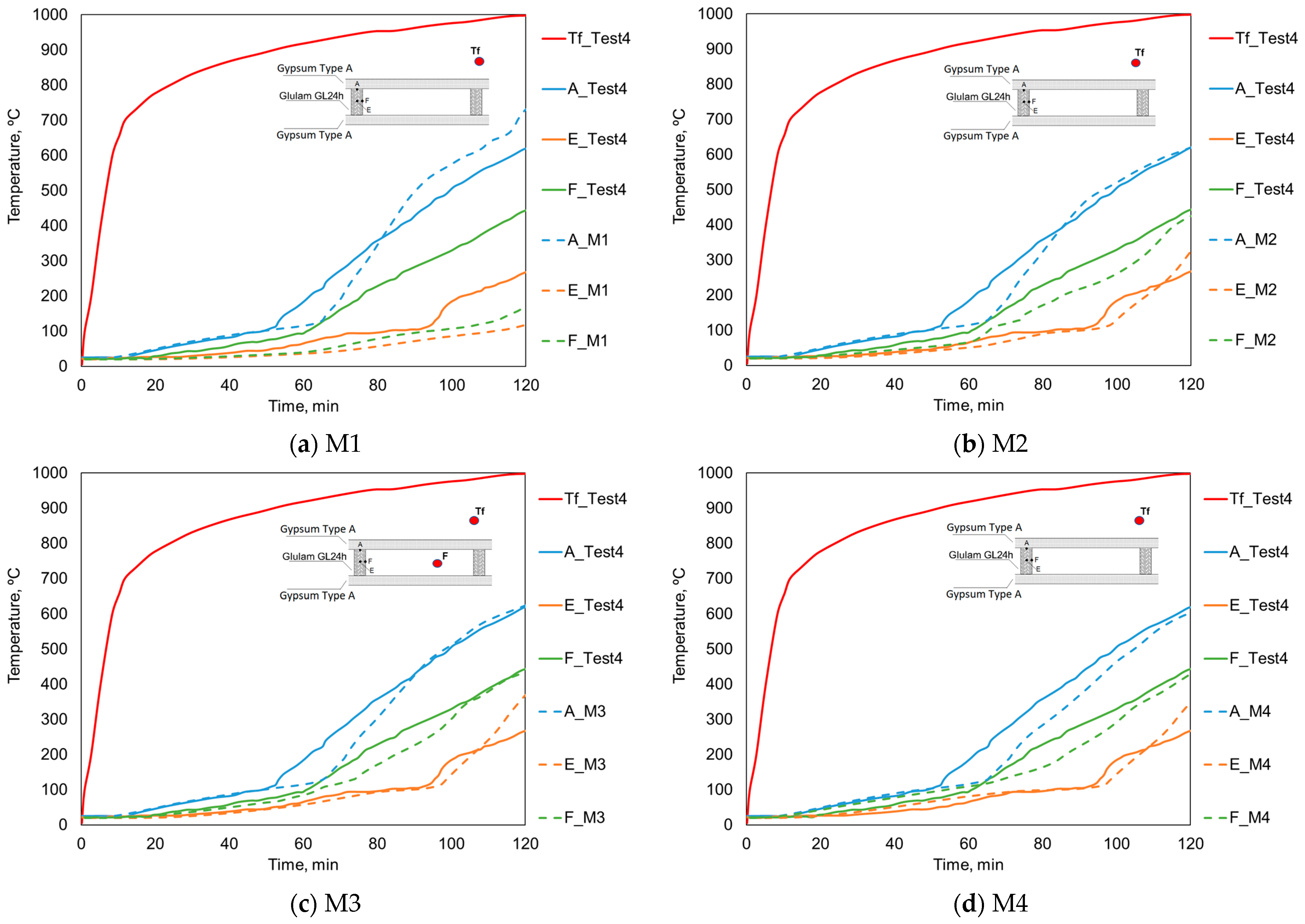
Finally, a total simulation time of 240 min was considered, except for the study of the model with different gypsum board thicknesses, in which it was necessary to extend the simulation up to 300 min to calculate the residual cross-section. The temperature field evaluation at control points A, E, and F, in accordance with the consideration of the experimental validation model M4, is represented in Figure 7.
In this way, descriptive curves of the time evolution of temperature were drawn up. The temperature fields obtained for the models related to the study of the distance between centers (D) are represented in Figure 7a. To compare the temperature evolution curves of the wood height (H) study, the temperature fields are represented in Figure 7b. The study of the wood width (W), referring to the models under analysis, is represented in Figure 7c. The study of gypsum board thickness (Tg) is represented in Figure 7d.
Analyzing the results obtained for the study of the distance between centers (D), it is concluded that the temperature fields of the different models present a high similarity, with the slopes of the curves being approximately the same. However, it appears that a smaller distance between centers, in this case, equal to 400 mm, allows a slightly delayed increase in temperature to be obtained when compared to distances of 500 and 600 mm.
Based on the results obtained for the temperature field resulting from the study of the wood height (H), the slopes of the curves in the three models are similar. Regarding control point A, it is also possible to conclude that the temperature field at this point is not influenced by the variation in the wood height. Around points E and F, despite the curves having the same slope, the increase in the wood height causes a delay in the temperature evolution. Thus, it appears that the model with the best performance regarding the time evolution of temperature is the one defined by [120 × 30 + 12.5] × 400.
Analyzing the results obtained for the temperature field referring to the study of the wood width (W), at points A and F, the results confirm the previous conclusions, there is a linear evolution of temperature between the exposed face to the fire and the top of the beam, which depends, mainly, on thermal conduction in the gypsum board. Finally, increasing the width of the wood leads to better performance, as evidenced by the analysis of the temperature evolution at control point E. At this point, heating above 100 °C occurs for approximately 65 min for the model [120 × 50 + 12.5] × 400, while in the model [120 × 30 + 12.5] × 400 it is 45 min. With this, it can be concluded that, of the models under study, the one that allows obtaining better performance in terms of the temperature field is [120 × 50 + 12.5] × 400.
The results from the study of the gypsum board thickness (Tg), it is the one that produces greater variations in the evolution of temperatures when compared to the others.
Regarding control point A, the temperature evolution becomes significantly delayed between models.
Concerning control points E and F, the temperature evolution with low slopes happens in the [120 × 50 + 25] × 400 model. This phenomenon is justified by the fact that the greater gypsum board thickness slows down the heating by radiation and convection inside the air cavities. With this, the analysis of the temperature field allows us to conclude that the model with the best performance is [120 × 50 + 25] × 400.

3.2. Residual Cross-Section

The numerical models developed within the scope to study the effect of different geometric parameters were evaluated considering the evolution of the char layer over time. To compare the influence of the geometric parameters, schematic images were obtained for the time instants 30, 60, 90, and 120 min, which correspond to time scales defined for non-bearing construction elements by standard EN 13501-2:2007 [27] and based on RJ-SCIE [28].
In all models, the limit temperature for the formation of the char layer was imposed considering the reference of 300 °C imposed by EC5-1-2, EN 1995-1-2 (2003) [1]. Thus, the calculation of the residual section presented in Table 3 was obtained.
Considering the results obtained in Table 4, it is concluded that the residual section in the models under study only differs at the time point of 60 min, since at 30 min there is no charred area and at 90 and 120 min amounts are charred.
Also, in conclusion, with a 10 mm increment between models in width (W) of the beam, there is an increase of approximately 50% in the residual cross-section between the models [120 × 30 + 12.5] × 400 and [120 × 40 + 12.5] × 400, while from the model [120 × 50 + 12.5] × 400 the residual cross-section only increases around 10%. With this, width increments in the same dimension do not cause a linear increase in the residual cross-section. At 90 min, the smallest width model has no residual cross-section, while the largest width model has slightly better performance than the intermediate width model.
Analyzing the remaining results, it is concluded that the model [120 × 50 + 25] × 400 presents the best performance among all models evaluated in terms of residual cross-section and thermal insulation criteria, assuming a fire resistance equal to 253.5 min.
Additionally, it is concluded that the geometric parameter with the greatest influence on the protection of the constructive solution is the thickness of the gypsum board, given that double the board layer, in this case from 12.5 to 25 mm, causes an increase in fire resistance of approximately 175 min. Thus, increasing the Tg parameter causes a better overall performance of the constructive solution.

3.3. Thermal Resistance Criterion

To evaluate the thermal insulation criterion, defined by standard EN 1363-1:2020 [20], different nodes located on the surface not exposed to fire were used, as previously represented in Figure 6, considering a time of exposure to fire for 300 min (4.5 h), to reach the limit temperatures of 160 °C and 200 °C.
The results obtained through the application of the thermal insulation criterion are represented in Table 5.
It is concluded that the model [120 × 50 + 25] × 400 presents the best performance among all the models evaluated in terms of residual section and thermal insulation criteria, assuming a fire resistance equal to 253.5 min. Additionally, it is concluded that the geometric parameter with the greatest influence on the protection of the construction solution is the thickness of the gypsum board, given that double the board layer, in this case from 12.5 to 25 mm, causes an increase in fire resistance of, approximately 175 min. Thus, increasing the Tg parameter causes a better overall performance of the constructive solution, which, based on Table 4, the Tg parameter allows a value equal to 25 mm.

3.4. Study Limitation

The numerical model presented and developed in this work was compared with two experimental tests carried out by the authors mentioned in [7]. In this work, only the evaluation with Test 4 [
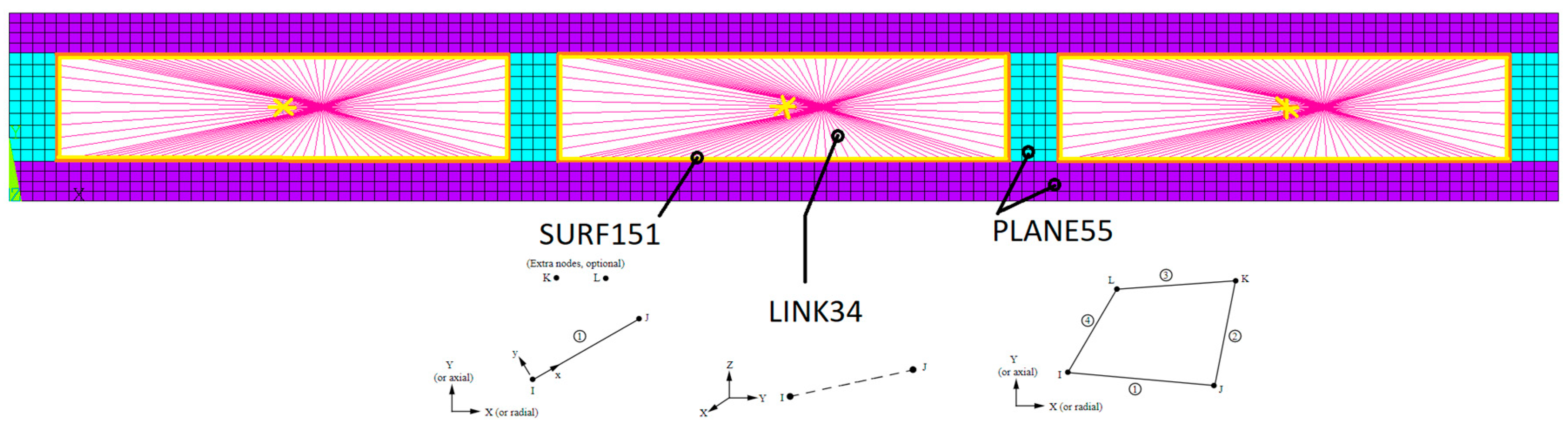
7] was presented. The authors consider that this number of validations may not be completely sufficient, and therefore suggest new comparison tests. However, an entire procedure was presented that could be useful and be followed in any future checks to be carried out. Furthermore, all the different numerical finite elements and their connectivity were verified and explained, which allowed a potential solution to be used to study the effect of heat inside a hollow cavity in wooden elements exposed to fire.

4. Conclusions

This new parametric numerical model made it possible to evaluate the general influence of the variation in geometric dimensions associated with structural wooden support elements with gypsum board protection in an easy way when compared to the experimental methodologies used. It was possible to analyze the evolution of the temperature inside the cavity and approximate this value closer to that obtained in experimental methodology, using an additional finite element. This procedure could be used for any other simulations to calculate the fire resistance in these types of structures.
This analysis followed a fire resistance methodology using the thermal insulation criterion. It is concluded that the evolution of fire resistance, when studying the distance between wood centers, appears practically linear, with only a small variation. Regarding the height and width of the wood, both parameters do not verify linearity, as the existing variation differs from what is expected.
Likewise, when comparing the models for studying gypsum board thickness, there is a greater divergence, with the evolution observed in the numerical simulation being much higher than expected. Additionally, it is possible to assess the importance of the parameters in the performance of the constructive solution.
Therefore, it is concluded that the increase in gypsum board thickness is the parameter with the greatest preponderance in fire resistance, as it causes the greatest variation. The second parameter, with the greatest positive impact on fire resistance, is the height of the wood, followed by the wood width.
Finally, the parameter with less significant importance concerns the variation in the distance between wooden beam centers, given that increasing it causes a very small increase in the performance of the constructive solution. The numerical model was validated and developed by the finite element method and can be used for another type of constructive model to assess fire resistance.
Future work intends to investigate the effect of different types of insulation and thickness layers, under the constructive element under fire, in the assessment of the residual cross-sections. Additionally, to include steel connections in the assembly parts of the constructive model and verify the effect on fire resistance. Furthermore, the effect of internal protection inside the air cavity will be another study to consider. With different results, Different results could aid in finding a simplified and analytical model that can predict all these combinations.

Author Contributions

Conceptualization, E.M.M.F.; methodology, M.O.; validation, D.P., investigation, D.P.; writing—original draft preparation, E.M.M.F.; writing—review and editing, E.M.M.F. and M.O.; supervision, E.M.M.F. All authors have read and agreed to the published version of the manuscript.

Funding

This research received no external funding.

Institutional Review Board Statement

Not applicable.

Informed Consent Statement

Not applicable.

Data Availability Statement

Data are contained within the article.

Conflicts of Interest

The authors declare no conflicts of interest.

References

  1. European Committee for Standardization. Eurocode 5: Design of Timber Structures. Part 1-2: General Structural Fire Design; BSI: Brussels, Belgium, 2004. [Google Scholar]
  2. White, R.H.; Nordheim, E.V. Charring rate of wood for ASTM E119 exposure. Fire Technol. 1992, 28, 5–30. [Google Scholar] [CrossRef]
  3. Mangs, J.; Hostikka, S. Experiments and Numerical Simulations of Vertical Flame Spread on Charring Materials at Different Ambient Temperatures. Fire Saf. Sci. 2011, 10, 499–512. [Google Scholar] [CrossRef]
  4. Yang, F.; Rippe, C.; Hodges, J.; Lattimer, B. Methodology for material property determination. Fire Mater. 2019, 43, 694–706. [Google Scholar] [CrossRef]
  5. Rogaume, T. Thermal decomposition and pyrolysis of solid fuels: Objectives, challenges, and modelling. Fire Saf. J. 2019, 106, 177–188. [Google Scholar] [CrossRef]
  6. Hehnen, T.; Arnold, L.; La Mendola, S. Numerical Fire Spread Simulation Based on Material Pyrolysis—An Application to the CHRISTIFIRE Phase 1 Horizontal Cable Tray Tests. Fire 2020, 3, 33. [Google Scholar] [CrossRef]
  7. Takeda, H.; Mehaffey, J.R. WALL2D: A Model for Predicting Heat Transfer through Wood-Stud Walls Exposed to Fire. Fire Mater. 1998, 22, 133–140. [Google Scholar] [CrossRef]
  8. Takeda, H. An Integrated Model to Predict Fire Resistance of Wood Floor Assemblies. J. Fire Prot. Eng. 2009, 19, 133–150. [Google Scholar] [CrossRef]
  9. Frangi, A.; Fontana, M. Charring rates and temperature profiles of wood sections. Fire Mater. 2003, 27, 91–102. [Google Scholar] [CrossRef]
  10. ISO 834-1: Fire Resistance Tests-Elements of Building Construction-Part 1: General Requirement. Available online: https://www.iso.org/standard/2576.html (accessed on 10 November 2023).
  11. Frangi, A.; Fontana, M.; Hugi, E.; Jübstl, R. Experimental analysis of cross-laminated timber panels in fire. Fire Saf. J. 2009, 44, 1078–1087. [Google Scholar] [CrossRef]
  12. Yang, T.-H.; Wang, S.-Y.; Tsai, M.-J.; Lin, C.-Y. The charring depth and charring rate of glued laminated timber after a standard fire exposure test. Build. Environ. 2009, 44, 231–236. [Google Scholar] [CrossRef]
  13. Frangi, A.; Schleifer, V.; Fontana, M.; Hugi, E. Experimental and Numerical Analysis of Gypsum Plasterboards in Fire. Fire Technol. 2010, 46, 149–167. [Google Scholar] [CrossRef]
  14. Frangi, A.; Schleifer, V.; Fontana, M. Design model for the verification of the separating function of light timber frame assemblies. Eng. Struct. 2010, 32, 1184–1195. [Google Scholar] [CrossRef]
  15. Bartlett, A.I.; Hadden, R.M.; Bisby, L.A. A Review of Factors Affecting the Burning Behaviour of Wood for Application to Tall Timber Construction. Fire Technol. 2019, 55, 1–49. [Google Scholar] [CrossRef]
  16. Fahrni, R.; Klippel, M.; Just, A.; Ollino, A.; Frangi, A. Fire tests on glued-laminated timber beams with specific local material properties. Fire Saf. J. 2019, 107, 161–169. [Google Scholar] [CrossRef]
  17. Fragiacomo, M.; Menis, A.; Moss, P.J.; Clemente, I.; Buchanan, A.H.; de Nicolo, B. Predicting the fire resistance of timber members loaded in tension. Fire Mater. 2013, 37, 114–129. [Google Scholar] [CrossRef]
  18. Thi, V.D.; Khelifa, M.; Oudjene, M.; el Ganaoui, M.; Rogaume, Y. Numerical simulation of fire integrity resistance of full-scale gypsum-faced cross-laminated timber wall. Int. J. Therm. Sci. 2018, 132, 96–103. [Google Scholar] [CrossRef]
  19. Piloto, P.A.G.; Fonseca, E.M.M. Timber framed walls lined with gypsum plates under fire. In Proceedings of the IRF2020: 7th International Conference Integrity-Reliability-Failure, Funchal, Portugal, 6–10 September 2020; Gomes, J.F.S., Meguid, S.A., Eds.; INEGI-FEUP: Porto, Portugal, 2020; pp. 547–556. [Google Scholar]
  20. CEN. EN 1363-1; Fire Resistance Tests Part 1: General Requirements. CEN: Brussels, Belgium, 2012.
  21. CEN. EN 1364-1; Fire Resistance Tests for Non-Loadbearing Elements. Part 1: Walls. CEN: Brussels, Belgium, 2015.
  22. Decreto-Lei nº 220/2008; Regime Jurídico de Segurança Contra Incêndio em Edifícios—RJSCIE. Ministério da Administração Pública: Lisboa, Portugal, 2008.
  23. Zhang, C.; Li, G.-Q. Modified One Zone Model for Fire Resistance Design of Steel Structures. Adv. Steel Constr. 2013, 9, 282–297. [Google Scholar]
  24. ANSYS, Inc. ANSYS Mechanical APD 2022 R2, Release 2; Southpointe: Canonsburg, PA, USA, 2022. [Google Scholar]
  25. Gomes, C.; Fonseca, E.M.M.; Lopes, H.M. Thermomechanical Analysis of Steel-to-Timber Connections under Fire and the Material Density Effect. Appl. Sci. 2022, 12, 10516. [Google Scholar] [CrossRef]
  26. Ujma, A.; Umnyakova, N. Thermal efficiency of the building envelope with the air layer and reflective coatings. E3S Web Conf. 2019, 100, 00082. [Google Scholar] [CrossRef]
  27. EN 13501-2:2007; Fire Classification of Construction Products and Building Elements—Part 2: Classification Using Data from Fire Resistance Tests, Excluding Ventilation Services. European Standard: Brussels, Belgium, 2009.
  28. Decreto-Lei nº 123/2019; Regime Jurídico da Segurança Contra Incêndio em Edifícios. Assembleia da Républica: Lisboa, Portugal, 2019.
Figure 1. Model in study: (a) Wooden constructive model; (b) Measuring points; (c) Dimensions.
Applsci 14 01477 g001
Figure 2. Mesh and boundary conditions. Cavity with (a) M1—air mesh; (b) M2—radiation; (c) M3—heating curve; (d) M4—radiation and convection. The light blue color represents the wood, the violet color represents the gypsum board, and the red color represents the cavity.
Applsci 14 01477 g002
Figure 3. Temperature field. Cavity with (a) M1—air mesh; (b) M2—radiation; (c) M3—heating curve; (d) M4—radiation and convection.
Applsci 14 01477 g003
Figure 4. Mesh and finite elements, chosen numerical model M4. The light blue color represents the wood, the violet color represents the gypsum board, and the inner pink color represents the cavity.
Applsci 14 01477 g004
Figure 5. Constructive model [H × W × Tg] × D, control points and node location.
Applsci 14 01477 g005
Figure 6. Boundary conditions for the new numerical model. The light blue color represents the wood, and the violet color represents the gypsum board.
Applsci 14 01477 g006
Figure 7. Temperature field. (a) D; (b) H; (c) W; (d) Tg.
Applsci 14 01477 g007
Table 1. Quantitative observations for models M3 and M4: n, M, SD, and SEM.
Model Controlled Points
AEF
M3n152129141
M284.61121.89190.57
SD222.8789.51140.91
SEM18.087.8811.87
M4n138127142
M246.32111.86164.93
SD198.9081.28126.90
SEM16.937.2110.65
Table 2. Residual wood cross-section (R) and relative error (e), %.
ModelArea, mm2 90 min100 min110 min120 min
Test 4 [7]3382 81.865.751.725.6
M23382R100.096.692.188.2
e22.2547.0378.14244.53
M33382R100.092.672.636.4
e22.2540.9440.4342.19
M43382R96.888.351.313.3
e18.3434.400.7748.05
Table 3. New numerical parametric models.
Parameter in StudyDimension [H × W + Tg] × DBest Performance
D[70 × 30 + 12.5] × 400[70 × 30 + 12.5] × 500[70 × 30 + 12.5] × 600D1
H[70 × 30 + 12.5] × D1[90 × 30 + 12.5] × D1[120 × 30 + 12.5] × D1H1
W[H1 × 30 + 12.5] × D1[H1 × 40 + 12.5] × D1[H1 × 50 + 12.5] × D1W1
Tg[H1 × W1 + 12.5] × D1[H1 × W1 + 15] × D1[H1 × W1 + 25] × D1Tg1
Table 4. Calculation of the residual wood cross-section R, %.
Model
[H × W + Tg] × D
Area, mm2R, %
30 min
R, %
60 min
R, %
90 min
R, %
120 min
[70 × 30 + 12.5] × 40021001007.5400
[70 × 30 + 12.5] × 50021001007.1000
[70 × 30 + 12.5] × 60021001006.8700
[70 × 30 + 12.5] × 40021001007.5400
[90 × 30 + 12.5] × 40027001007.6800
[120 × 30 + 12.5] × 40036001007.9100
[120 × 30 + 12.5] × 40036001007.9100
[120 × 40 + 12.5] × 400480010058.202.430
[120 × 50 + 12.5] × 400600010067.989.990
[120 × 50 + 12.5] × 400600010067.989.990
[120 × 50 + 15] × 400600010094.2943.064.36
[120 × 50 + 25] × 400600010010099.1388.93
Table 5. Fire resistance, thermal insulation criterion.
Model
[H × W + Tg] × D
Fire Resistance, min
[70 × 30 + 12.5] × 60070.2
[70 × 30 + 12.5] × 50070.9
[70 × 30 + 12.5] × 40071.8
[90 × 30 + 12.5] × 40073.2
[120 × 30 + 12.5] × 40075.7
[120 × 40 + 12.5] × 40077.7
[120 × 50 + 12.5] × 40078.9
[120 × 50 + 15] × 400105.2
[120 × 50 + 25] × 400253.5
Disclaimer/Publisher’s Note: The statements, opinions and data contained in all publications are solely those of the individual author(s) and contributor(s) and not of MDPI and/or the editor(s). MDPI and/or the editor(s) disclaim responsibility for any injury to people or property resulting from any ideas, methods, instructions or products referred to in the content.

