1. Introduction
In recent years, research and development of legged robots has made remarkable progress, demonstrating outstanding motion control performance even in complex environments with irregular terrain and various obstacles [
1,
2,
3,
4,
5]. Some have even performed advanced motion control capabilities in challenging activities, such as parkour [
6]. However, these developments have been primarily limited to field environments, with relatively slow progress observed in the development of Underwater Legged Robots (ULRs).
Until now, most underwater robots have been designed as submarine-shaped Remotely Operated Vehicles (ROVs), commonly moving through water using propellers [
7,
8,
9]. In many cases, underwater tasks are carried out on surfaces such as the seafloor. However, the bodies of submarine-shaped ROVs, floating in the fluid can be pushed and experience oscillations when encountering underwater currents, leading to a decrease in control performance. Moreover, they require high energy consumption to maintain the position and posture of the body. To address these limitations, there is a growing focus on the development of ULRs, designed to enhance static stability by making direct contact with the surfaces [
10,
11].
Figure 1 illustrates the scenario concept of radial-type quadruped ULR under development. The robot attaches to the lower surface of the ship, walks on it, and removes entangled fishing nets from the propeller. This study specifically focused on the leg position control of this type of ULR.
In dynamic walking control, achieving faster control of the robot’s joints is crucial. However, in the case of underwater movement, the surrounding fluid directly affects the robot’s motion. Buoyancy makes the robot float, while drag and added mass act like sandbags tethered to the robot. Furthermore, the robot’s movement in the intended direction for control is impeded by the effects of lift and vortex. While these hydrodynamic effects are relatively simple to calculate in a static state, performing complex motion controls such as walking poses significant challenges due to their non-linearity and complexity. However, considering these factors is essential to enhance the motion control performance of ULRs [
12].
In general, robot position tracking control involves adjusting the torque output of the joints. However, if the control methods designed for robots operating in the air are applied underwater without modification, the control performance, such as position accuracy, will be reduced due to the reasons mentioned above.
In the case of a PD controller, a commonly used feedback control method, higher control gains are necessary to counteract the influence of the fluid and ensure higher position accuracy. However, this results in increased torque output in each joint, reducing compliance with disturbances. On the other hand, Computed Torque Control (CTC), a representative model-based control technique, typically utilizes the Newton–Euler method as a basis to reflect the dynamic characteristics of the robot and facilitate efficient calculation and control. However, in the process, the equation of motion must be exactly calculated, and the computation of the hydrodynamic effects during motion control is very challenging. In summary, the existing control methods designed for air environments are not suitable for application in underwater contexts.
In this study, we propose the hybrid control method that combines a deep learning neural network, based on experimental data, with a task-space PD controller and evaluate its tracking performance. Dynamic characteristics are acquired through deep learning to simplify compensation for the effects of fluid during the position-tracking control of a quadruped walking robot. This process eliminates the need to individually calculate the fluid’s dynamic characteristics, thereby reducing the computational complexity. Furthermore, it allows for the maintenance of higher position accuracy compared to a single task-space PD controller with lower torque output. Performance evaluation is carried out using an underwater 4-DOF robot leg modeled after the leg of the radial-type quadruped ULR. The evaluations are conducted in both air and water environments to confirm applicability in various environments.
The contributions of this study are as follows.
Through a deep learning model based on actual robot data, we considered non-linear factors, such as joint friction and fluid force, etc., which are challenging to calculate.
We proposed a deep learning-based robot leg control method that is applicable across various environments.
We employed a controller that combines feedback control with data-driven deep learning to increase its utility.
We employed a simpler model to ensure high positional accuracy and compliance, even with similar torque output.
2. Related Works
Jun et al. [
13] introduced a preliminary model of drag and lift forces acting on joint legs using a model of the underwater walking robot Crabster, conducting torque simulations with joint robot arms. Zarebidoki et al. [
14] utilized MATLAB Simulink’s Simscape toolbox to simulate fluid forces applied to the 3-DOF manipulator. In the study by Zhong et al. [
15], the calculation method for inertia and viscous fluid mechanics of underwater manipulators was summarized for dynamic analysis. They explored dynamic modeling from two perspectives, strip theory, and non-strip theory, to comprehend how the fluid mechanics of manipulators influence behavior and to study optimization for this. While these studies focused on accurately analyzing fluids, they did not apply position-tracking control to robots in the real world.
Yao et al. [
16] employed model reference adaptive control, adjusting in real time based on errors between reference and real models, to address challenges arising from non-linear dynamics and hydrodynamics. Wang et al. [
17] enhanced the control performance of the 4-DOF underwater manipulator by using dual integral sliding mode control in their study. Sagara et al. [
18] introduced the Resolved Acceleration Control (RAC) method to improve the control accuracy of the end effector and compared its performance with the CTC using an underwater robot equipped with two arms. Studies by Dai et al. [
19] proposed a trajectory tracking plan for an Underwater Vehicle-Manipulator System (UVMS), combining CTC with a modified H-infinity controller, and non-linear disturbance observer, successfully applying it through an online Grey Wolf Optimizer (GWO). Studies by Zhou et al. [
20] proposed a method that combines backstepping strategies with adaptive robust controllers for precise motion control of underwater manipulators. These studies overcome fluid-related challenges using model-based control, sometimes robust or adaptive control. However, the process has limitations, being overly complex and requiring extensive computation.
In recent times, the analysis of robot dynamics through machine learning has led to the development of control techniques for walking robots [
21,
22]. Polydoros et al. [
23] proposed deep learning algorithms for real-time dynamic learning, demonstrating that dynamic models adapt more effectively to real-time changes than other algorithms. However, these studies did not consider the underwater environment.
This study employs a deep learning neural network to simplify the computation of the dynamic model, proposing a control method applicable in both air and water environments and evaluating its position-tracking performance. The evaluation involves a comparison of the results with a single task-space PD control using a 4-DOF underwater robot leg.
3. Overviews of 4-DOF Underwater Robot Leg
As a test platform for applying and evaluating the hybrid control method, we constructed a 4-DOF underwater robot leg modeled after the robot in the scenario concept. The robot was designed for swimming underwater, incorporating 4-DOF per leg.
Figure 2 illustrates the robot leg under position tracking control. The water tank and the cradle were designed for mobility, enabling experiments in both air and water environments.
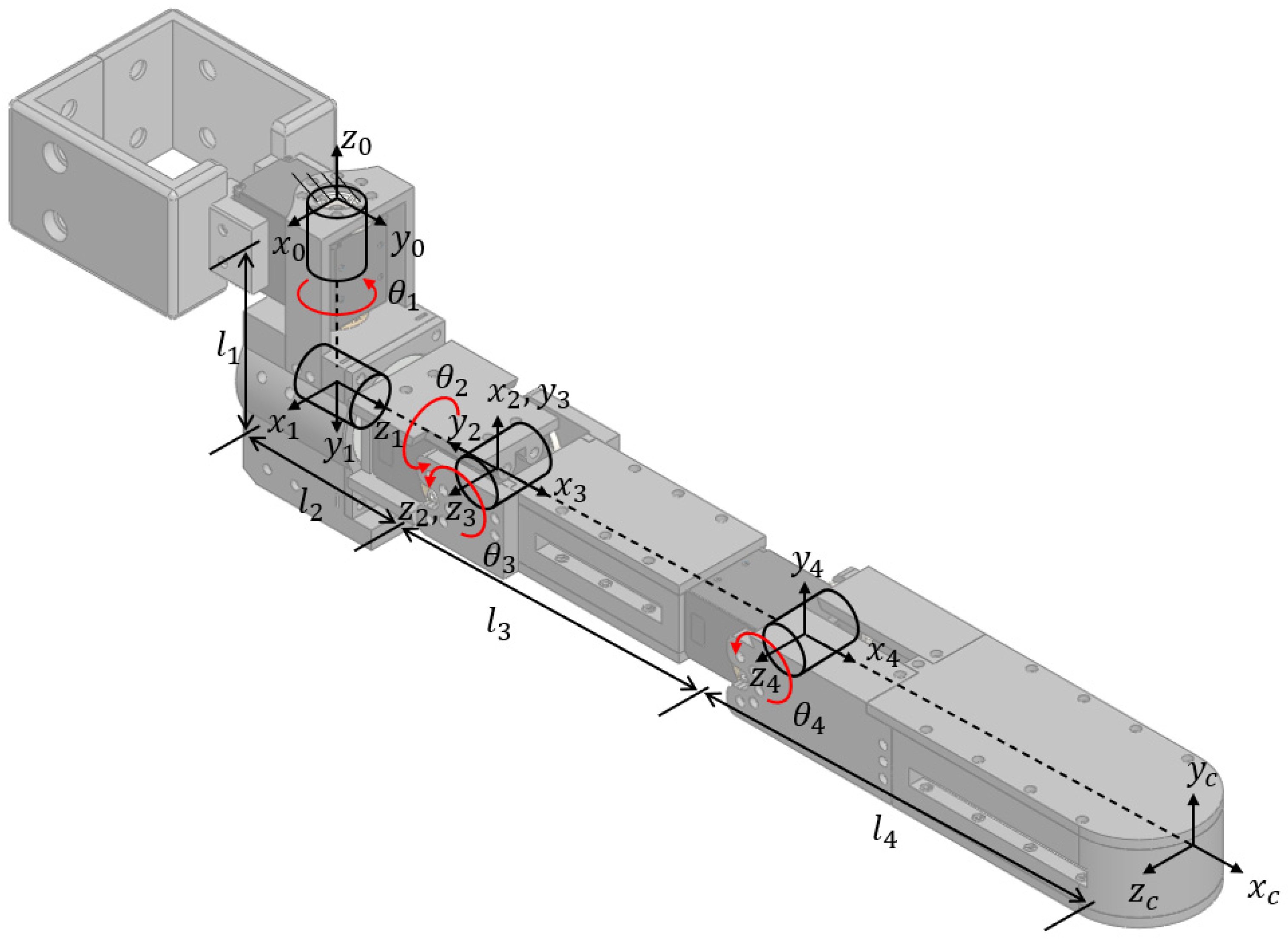
Figure 3 shows the joint configuration of the robot leg, and
Table 1 provides its specifications. To reduce weight and prevent corrosion underwater, we chose Onyx as the frame material, which is a micro carbon fiber-filled nylon designed for three-dimensional (3D) printers manufactured by Markforged Co. (Waltham, MA, USA) The water-proof motor selected is Robotis’ XW540-T140 model, and its specifications are detailed in
Table 2.
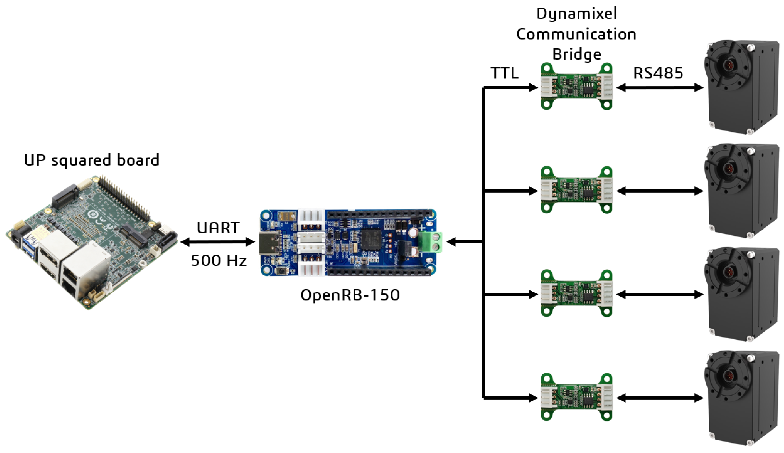
Figure 4 shows the control system of the robot leg. The UP-squared board was selected as the main controller. After generating the reference trajectory on the board, it is transmitted to the OpenRB-150 communication module via UART communication. After that, when the communication module sends a command to the Dynamixel communication bridge using TTL communication, the bridge switches to RS485 communication and transmits the command to each motor at a frequency of 500 Hz.
4. Torque Control Based on the Neural Network
4.1. Data Collection
For excellent learning performance, high-quality data is essential. To achieve this, we needed to prepare data that accurately reflects relevant aspects for learning dynamic characteristics. Most recently manufactured servo motors support high-performance position control. When a desired angle is input as the position command, the high-speed position controller within the motor driver generates the required torque to precisely follow the position input. In this process, the dynamic characteristics for moving the output link of the motor to the input position are reflected in the motor torque. Therefore, by employing machine learning based on the desired motion and joint torque output, we can calculate joint torque without the need for modeling and computation of the effects of the fluid. Moreover, non-linear factors, such as motor friction, can also be learned. Thus, based on the derived torque and motor encoder readings, we deemed the data meaningful and utilized it for learning. Relying solely on the reading of the motor encoders may appear to be somewhat less accurate, as it depends on the performance of the motor. However, the goal of this paper is to learn the dynamic patterns that occur during the interaction between the robot and the fluid in the real world. Therefore, even if there is an error in the encoder reading, the dynamic characteristics for that case can still be learned and reflected in the control itself.
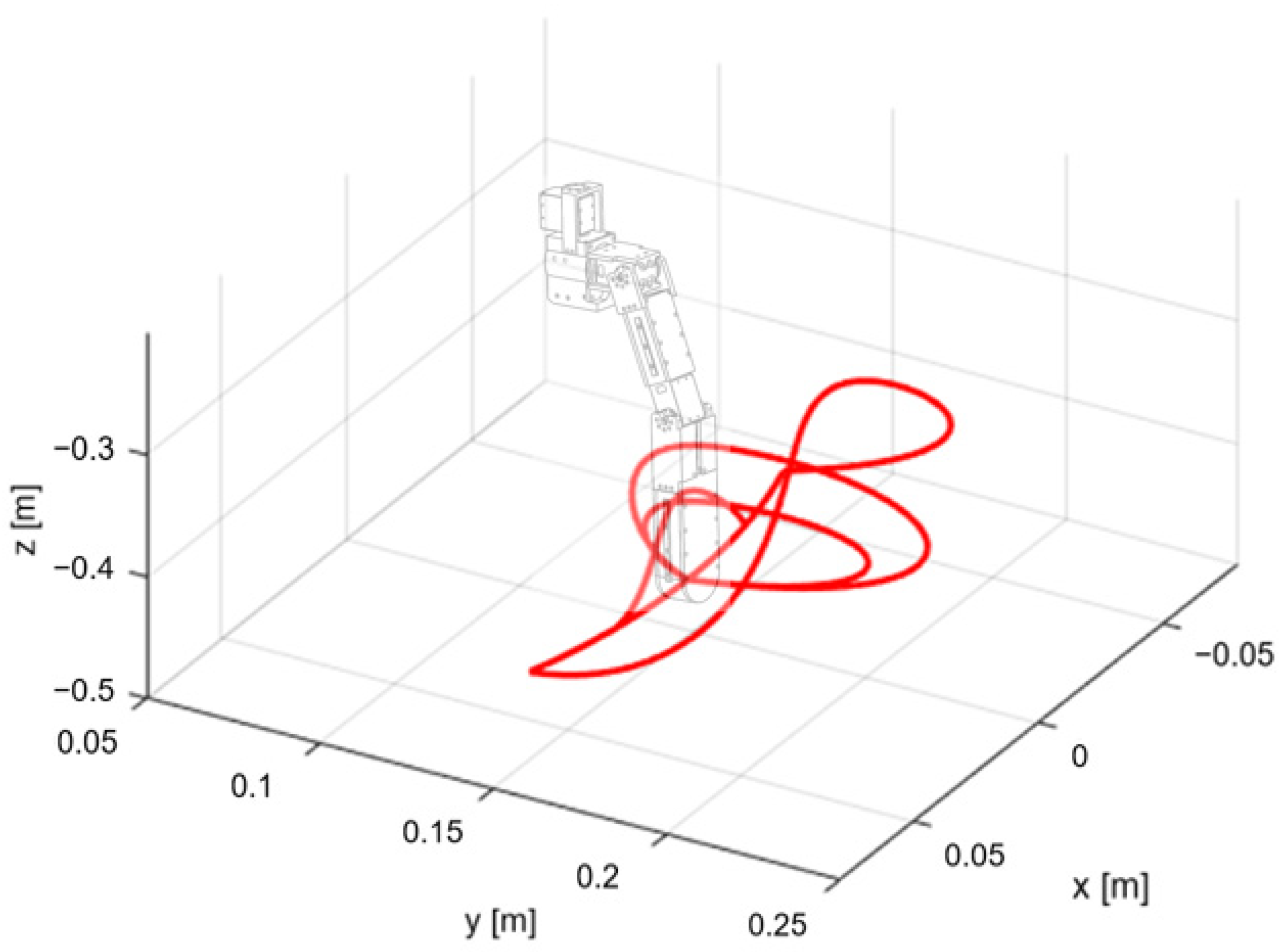
The radial-type quadruped walking robot, serving as the model for the test platform, exhibits the ability to move in various directions without rotating its body, thanks to its radially mounted legs. During the robot’s walking motions, the leg moves in two directions with respect to the body: forward and lateral. The training trajectory was set based on these motions, encompassing all aspects of low and high speeds, narrow and wide ranges, and both forward and lateral directions. While performing position tracking control of the training trajectory of the foot tip, we collected the input data set X, as depicted in
Figure 5.
The input data set
was constructed as follows.
where
is the angle of each joint,
denotes the angular velocity of each joint.
is the
,
, and
position of the foot tip and
is the pitch angle in task-space.
is the environment in which the robot is located. This data set
is labeled to determine the robot’s motion state based on input data. The motion of the robot leg is identified through the angle and angular velocity of the joint. The posture of the leg during the motion is identified by the position and orientation of the foot tip. The environment in which the robot is located is determined through
In the learning process, environmental data is automatically classified using one-hot encoding. In this study, data in both air and water environments are classified and learned, but the approach can be applied in more various environments. In the learning process, the neural network learns the relationship between the data set
and the measured joint torque. After this process, the neural network can predict the suitable joint torque for the input trajectory regardless of the environment.
4.2. Multi-Layer Perceptron (MLP) Design
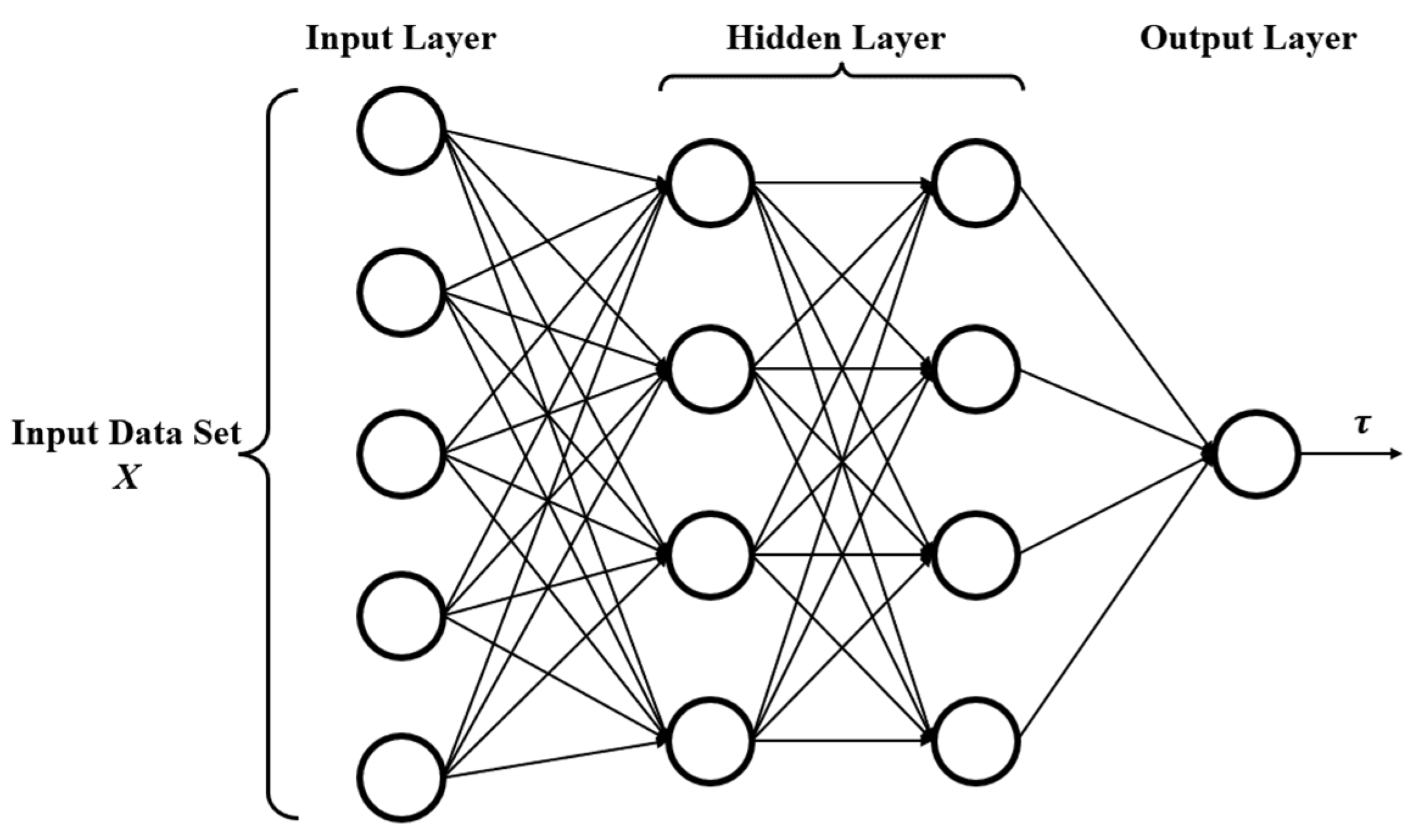
In this study, we designed an MLP neural network aiming to achieve precise reflection of dynamic characteristics. The neural network architecture consists of one input layer, two hidden layers, and one output layer. The data set
undergoes processing in the input layer as follows.
where
is processed data,
represents the weight matrix, and
is a bias vector. And
is the number of input variables, and
is the number of neurons in the layer. The ReLU activation function is employed in the hidden layer, where the data undergoes the following transformation.
where
represents the order of the layers (
) and
is the number of the layers. Additionally, a dropout layer is incorporated into the network to prevent overfitting. The Mean Squared Error (MSE) is employed as the loss function to enhance the accuracy of the predicted values, and it is calculated as follows.
where
is the predicted value, and
is the actual value. And
denotes the number of data points.
Through linear regression, we can predict joint torque even for trajectories that are not directly part of the learning process.
Figure 6 illustrates the structure of the designed MLP neural network. After successful learning based on the data set
from the training trajectory, we can predict joint torque
by inputting a data set for the reference trajectory
.
4.3. Hybrid Control Method
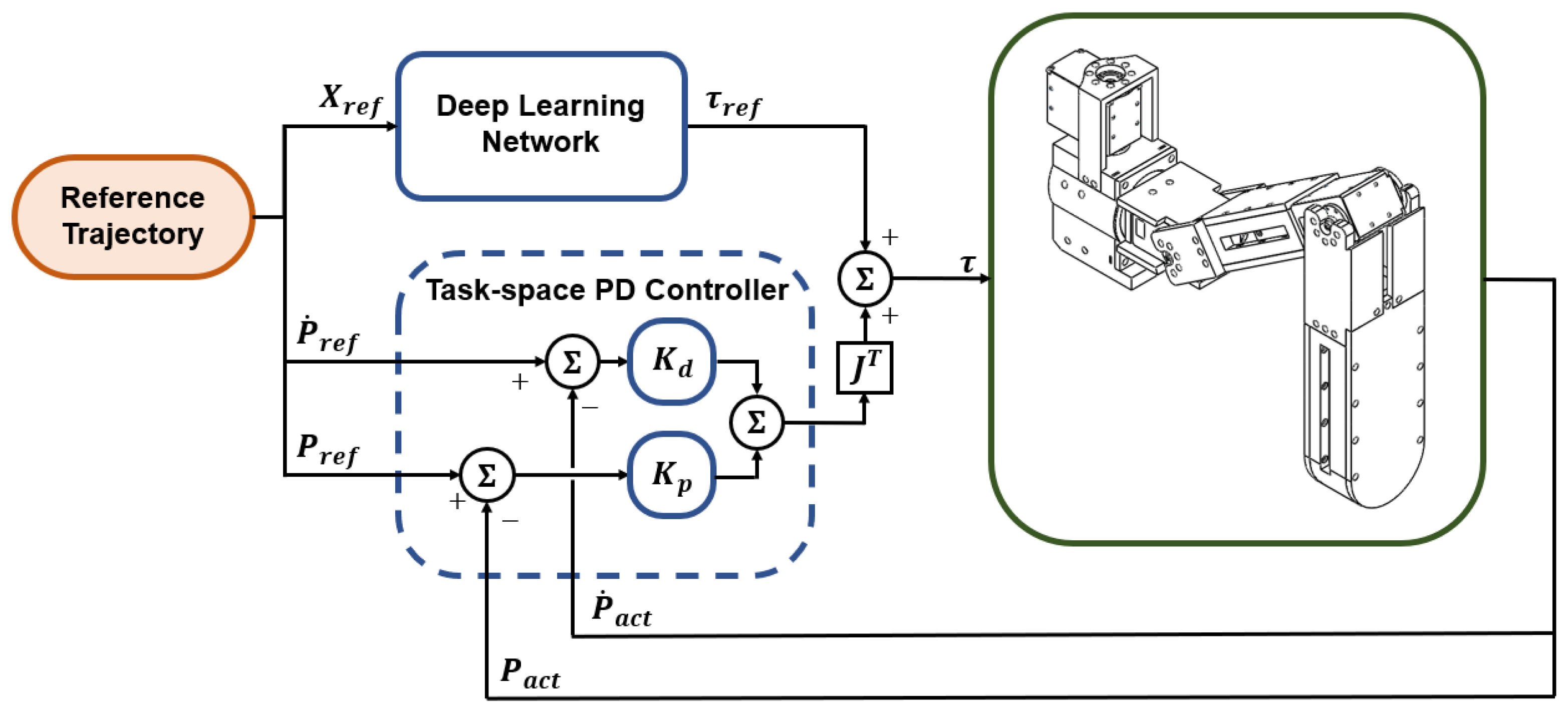
If only joint torque predicted by the neural network is directly input to the motor, it may not respond smoothly to errors. Additionally, as mentioned earlier, relying solely on a PD controller can lead to increased joint torque output and reduced compliance if the control gains are excessively raised for position accuracy. To address these shortcomings, we devised a hybrid controller by combining the task-space PD controller with the neural network. This hybrid approach compensates for both issues. By leveraging deep learning to overcome non-linear dynamic characteristics, we can achieve higher position accuracy without the need for excessively high PD control gain or complex computation. Furthermore, compliance and position accuracy can be secured even for trajectories that were not directly learned due to data limitations.
Figure 7 illustrates the diagram of the hybrid controller, combining the neural network and the task-space PD controller. The torque input
to each joint of the robot leg is as follows:
is the Jacobian matrix. are the reference position and velocity of the foot tip, and are the actual position and velocity of the foot tip. Obtained through forward kinematics based on motor encoder reading. The actual value may differ from the exact value due to errors in motor encoder reading. However, we assumed it was correct. Subsequently, we determined the PD control signal based on and and and , and then, multiply the control signal by the Jacobian matrix to implement PD control in the task-space.
5. Performance Evaluation
Two types of motion were designed for verification to mimic the movements of the quadruped walking robot, similar to the reference trajectory used to extract the data set . In this process, the motions were designated as lateral and forward motions, which are not directly used in the learning process.
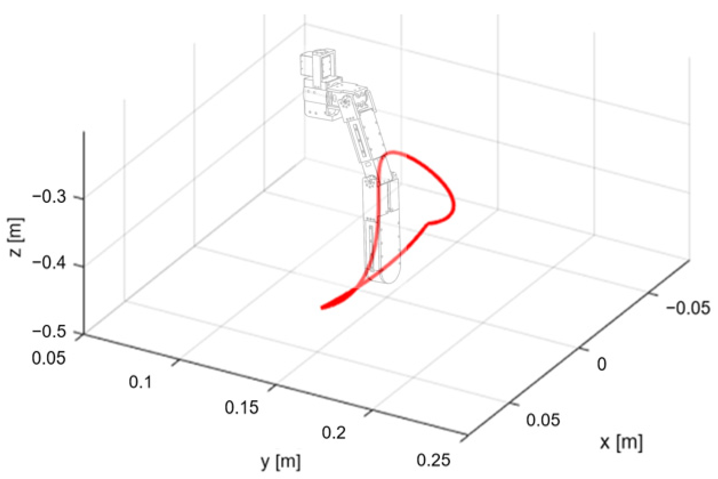
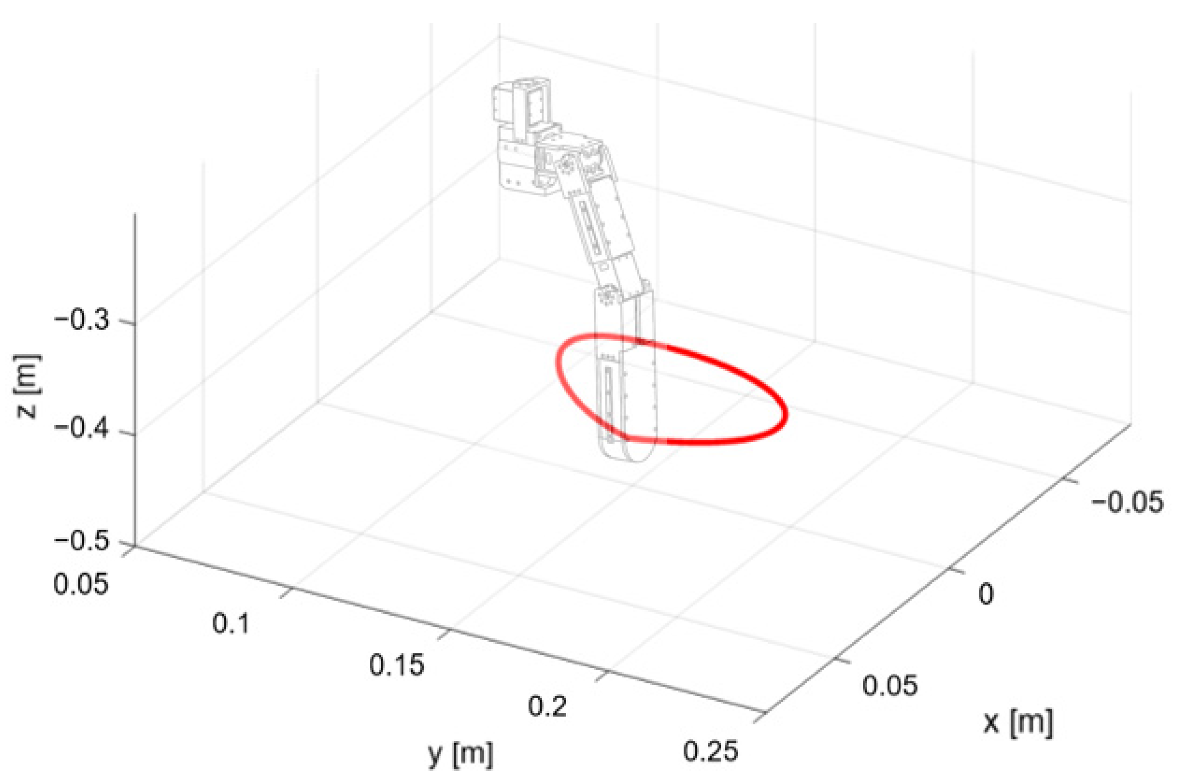
Figure 8 and
Figure 9 depict the reference trajectories of the foot tip during forward and lateral motions used in the verification in three-dimensional space. Based on these two trajectories, we compared the tracking performance of the single task-space PD controller and the hybrid controller in both air and water environments. The tracking performance criteria for comparison included the Root Mean Square Error (RMSE) values for the reference trajectory of the foot tip position and the Root Mean Square (RMS) values of each joint output torque. For more accurate verification, two cases were considered with different PD control gains: low (
), and high (
). Consequently, 16 position-tracking control experiments were performed [
24]. Video from [
24] shows the whole experiment and result.
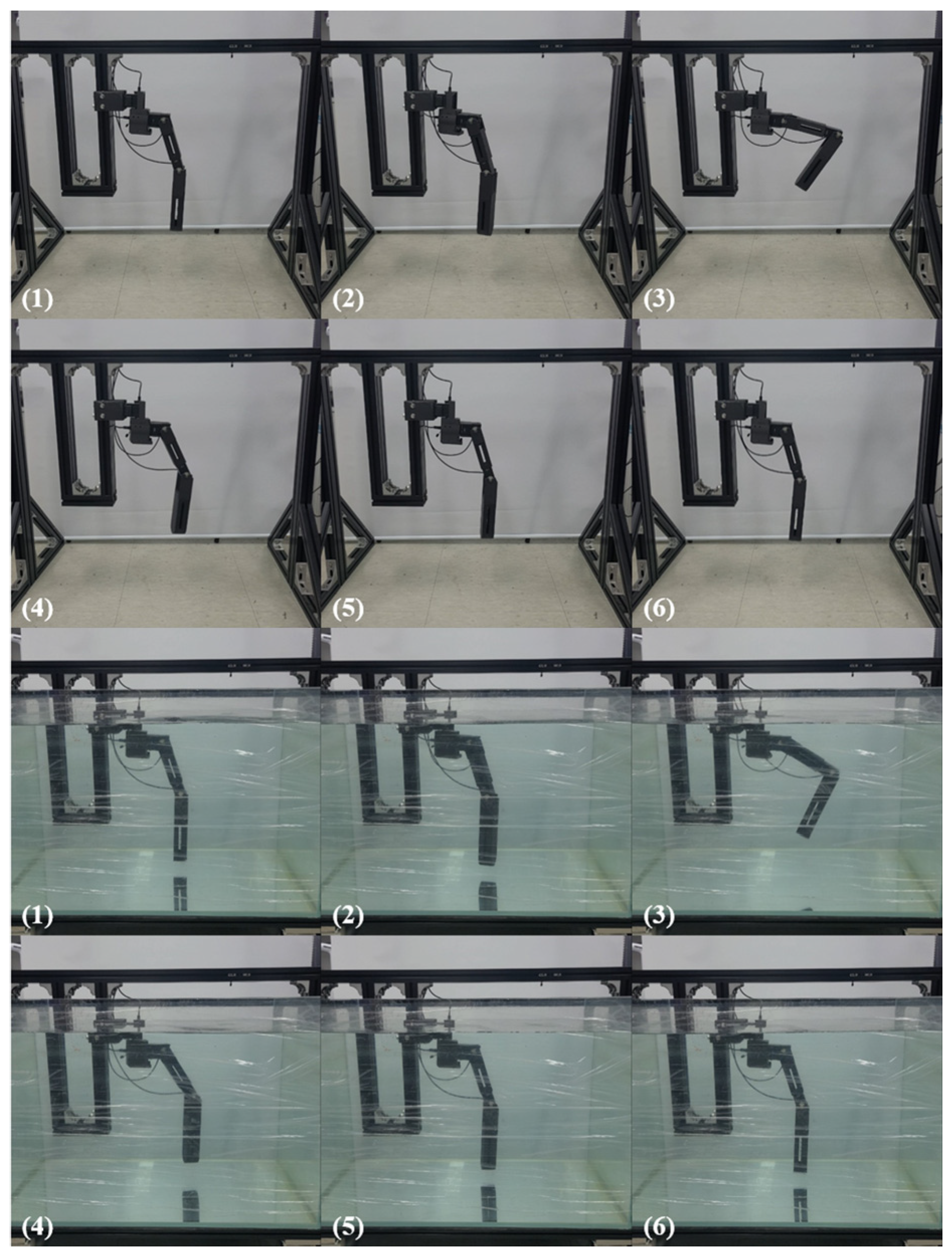
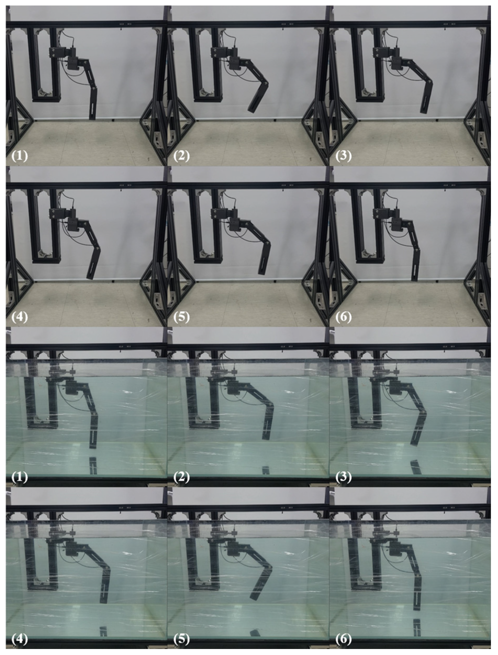
Figure 10 and
Figure 11 show the snapshots of experiments in air and underwater environments.
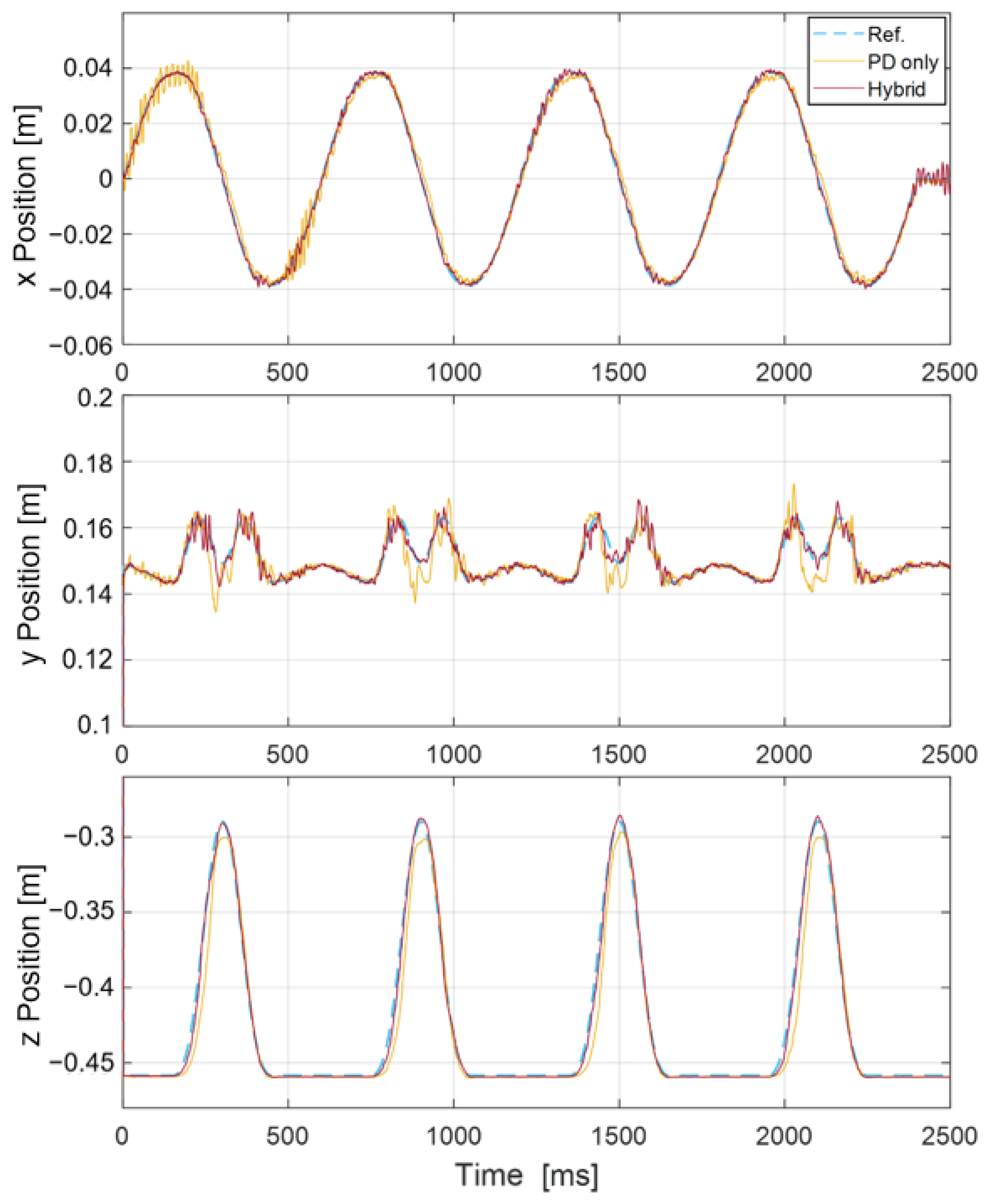
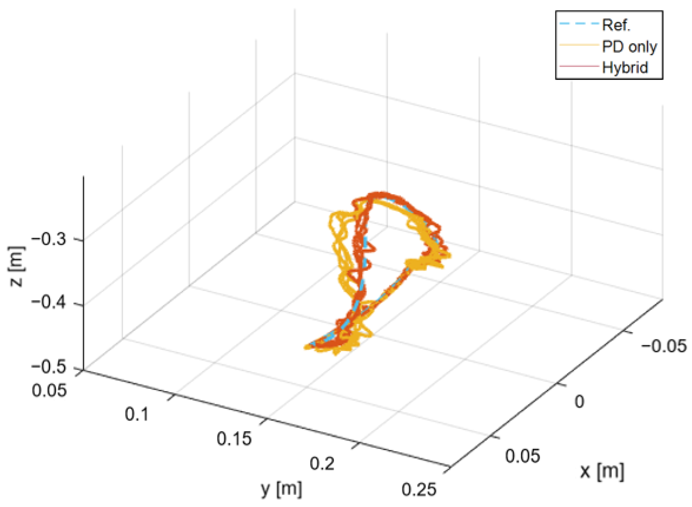
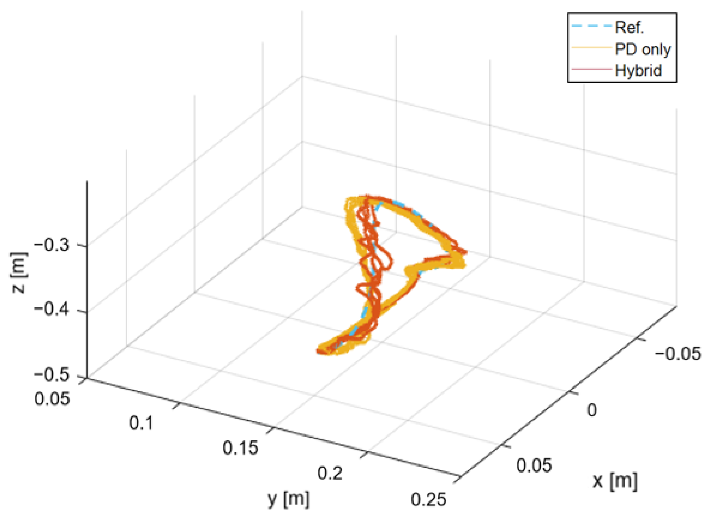
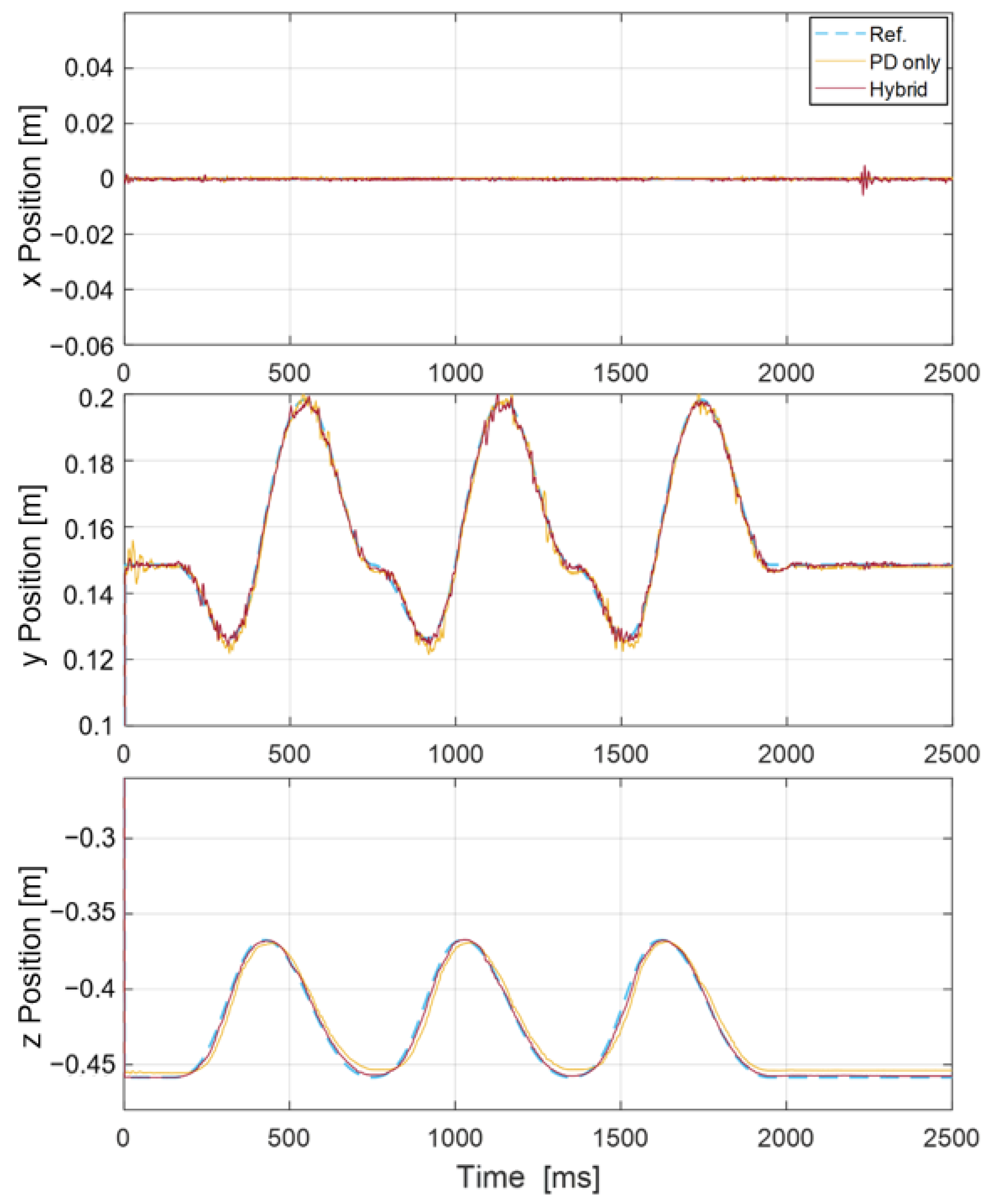
Figure 12 represents the trajectories of the foot tip in air during forward motion, measured with high PD control gains.
Figure 13 depicts the position paths of the foot tip of
Figure 12 in three-dimensional space. Correspondingly,
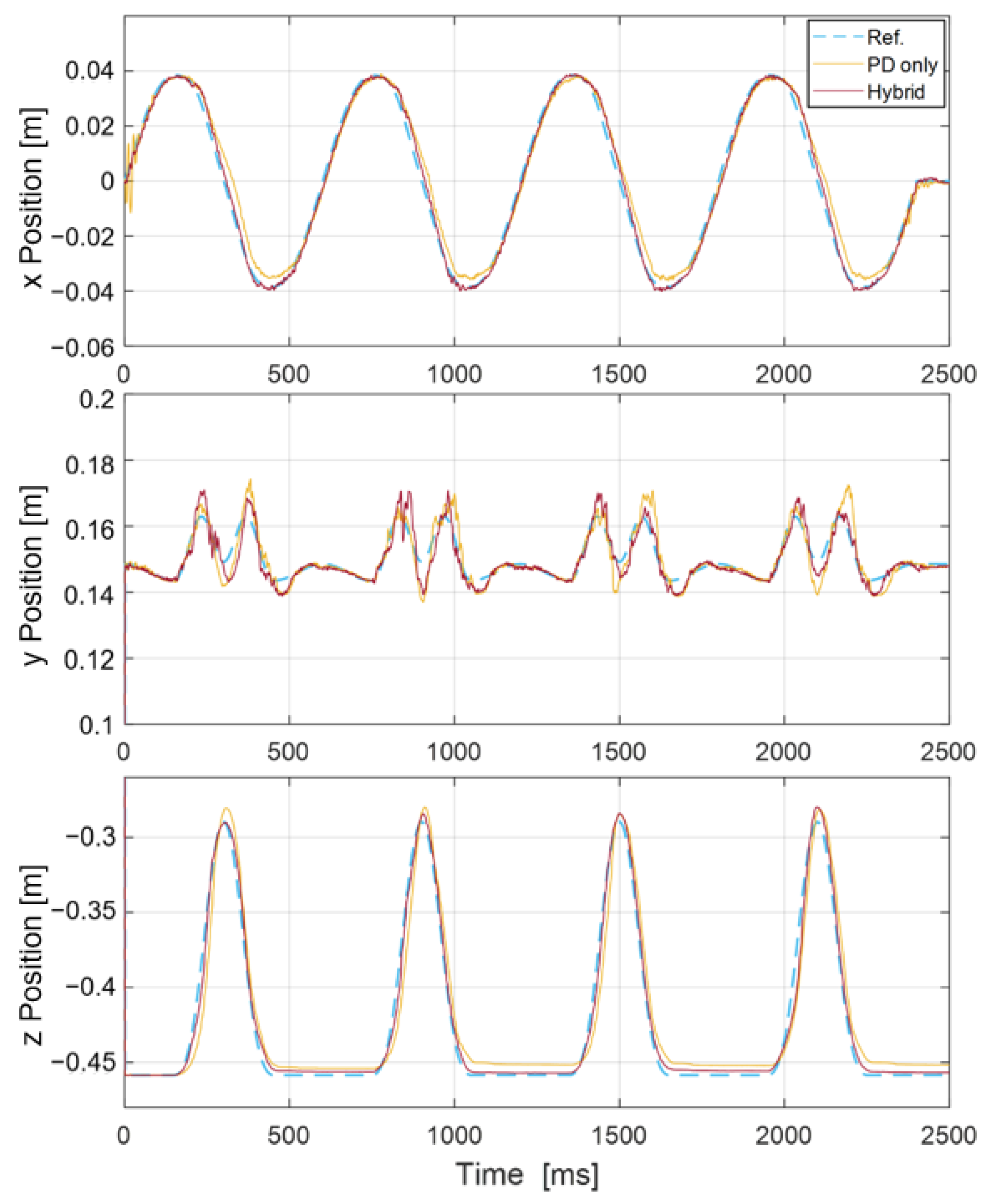
Figure 14 represents the trajectories of the foot tip in water during forward motion, measured with high PD control gains. And
Figure 15 depicts the position paths of the foot tip of
Figure 14 in three-dimensional space for each case.
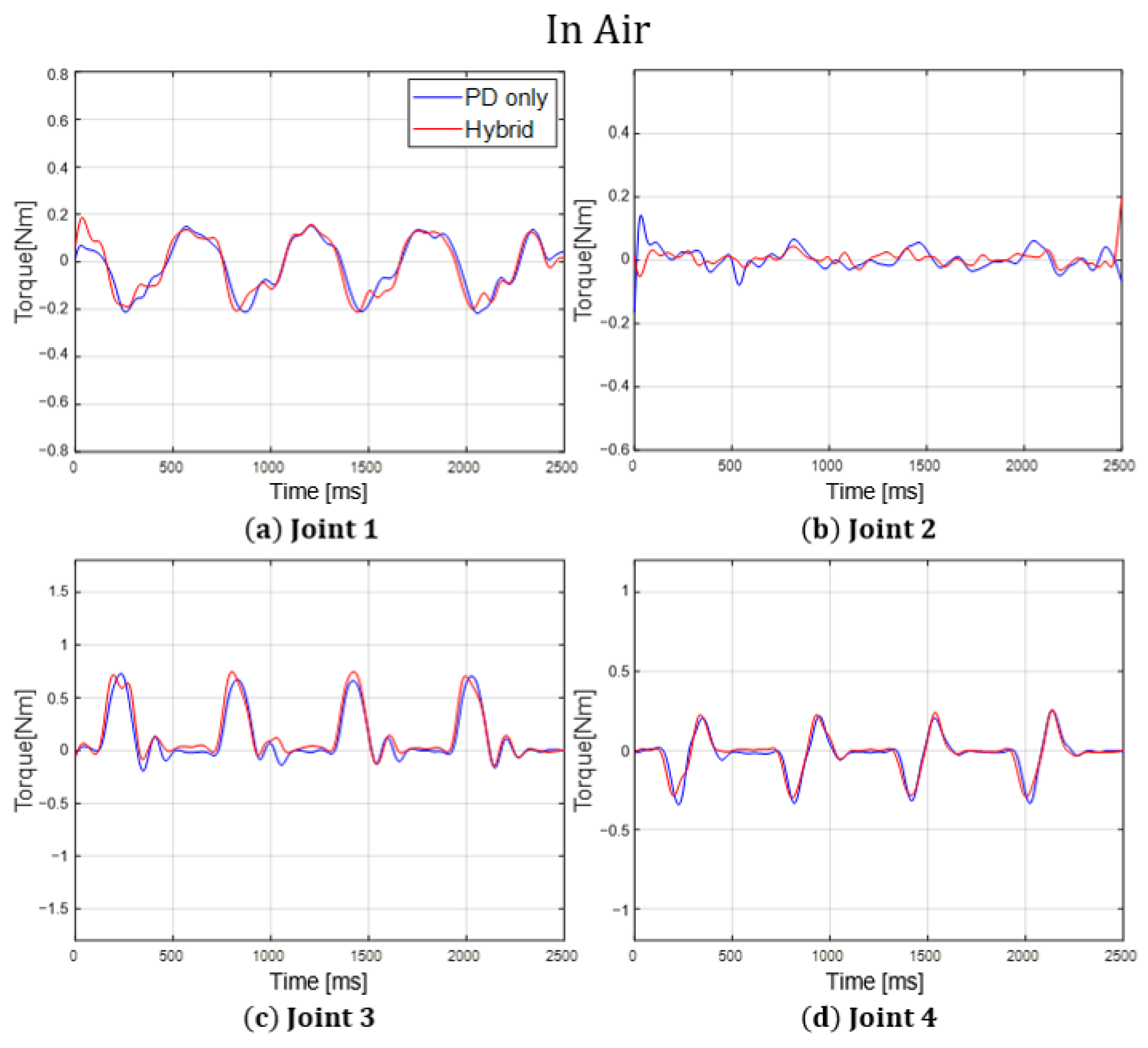
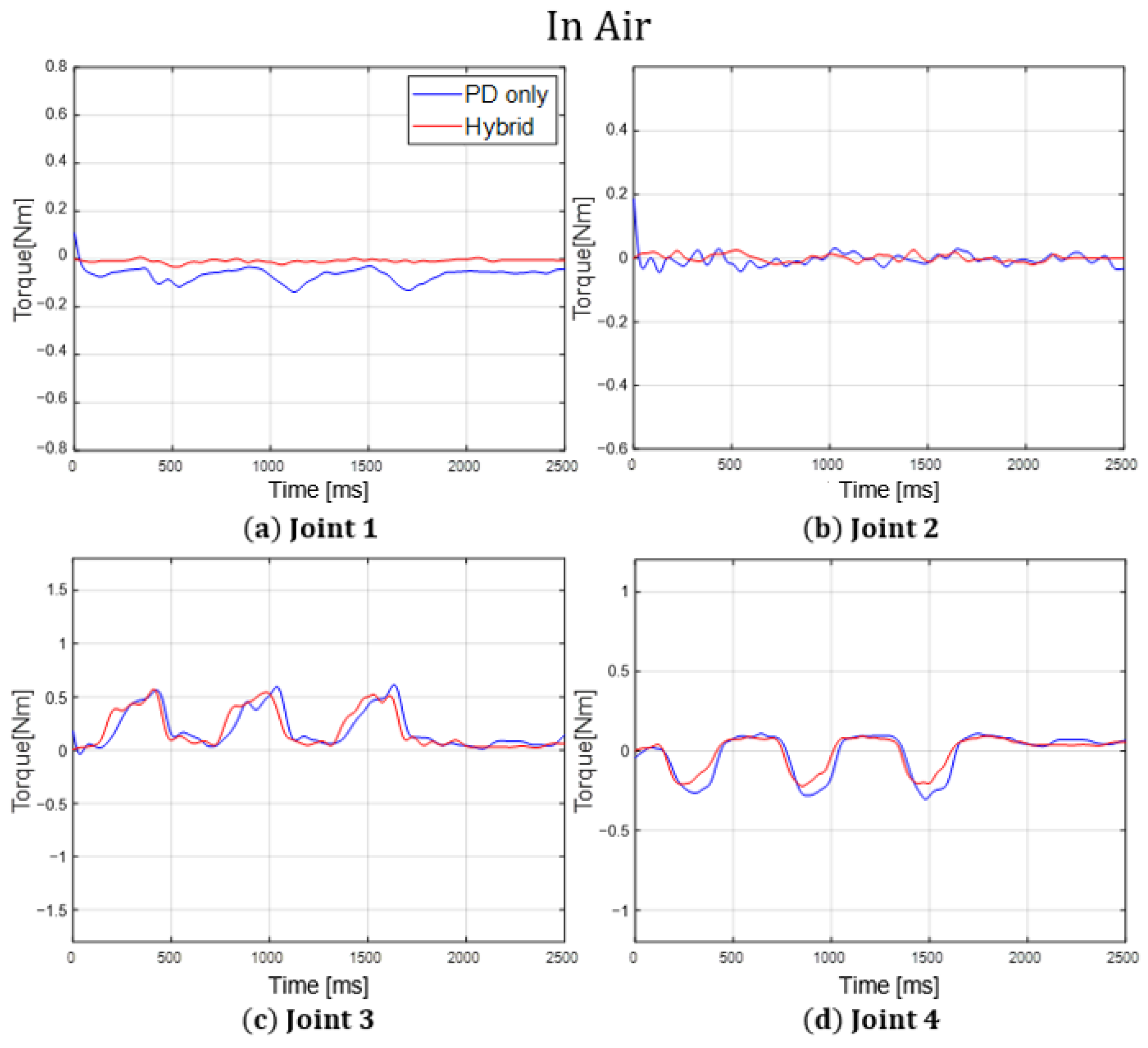
Figure 16 and
Figure 17 show the torque graphs of each joint for each environment during forward motion.
Similarly,
Figure 18 represents the trajectories of the foot tip in air during lateral motion, measured with high PD control gain.
Figure 19 depicts the position paths of the foot tip of
Figure 18 in three-dimensional space. Correspondingly,
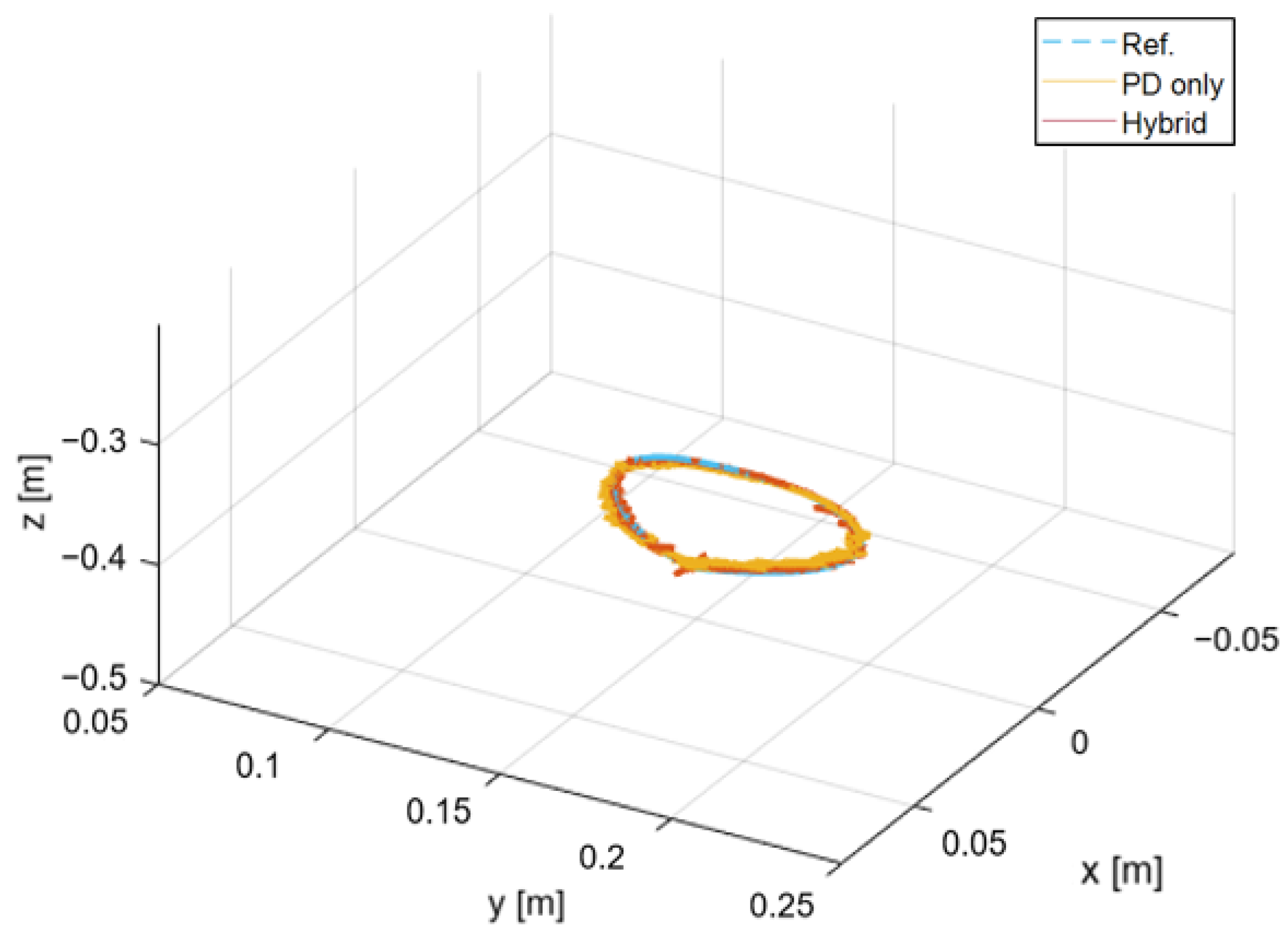
Figure 20 represents the trajectories of the foot tip in water during lateral motion, measured with high PD control gains. And
Figure 21 depicts the position paths of the foot tip of
Figure 20 in three-dimensional space.
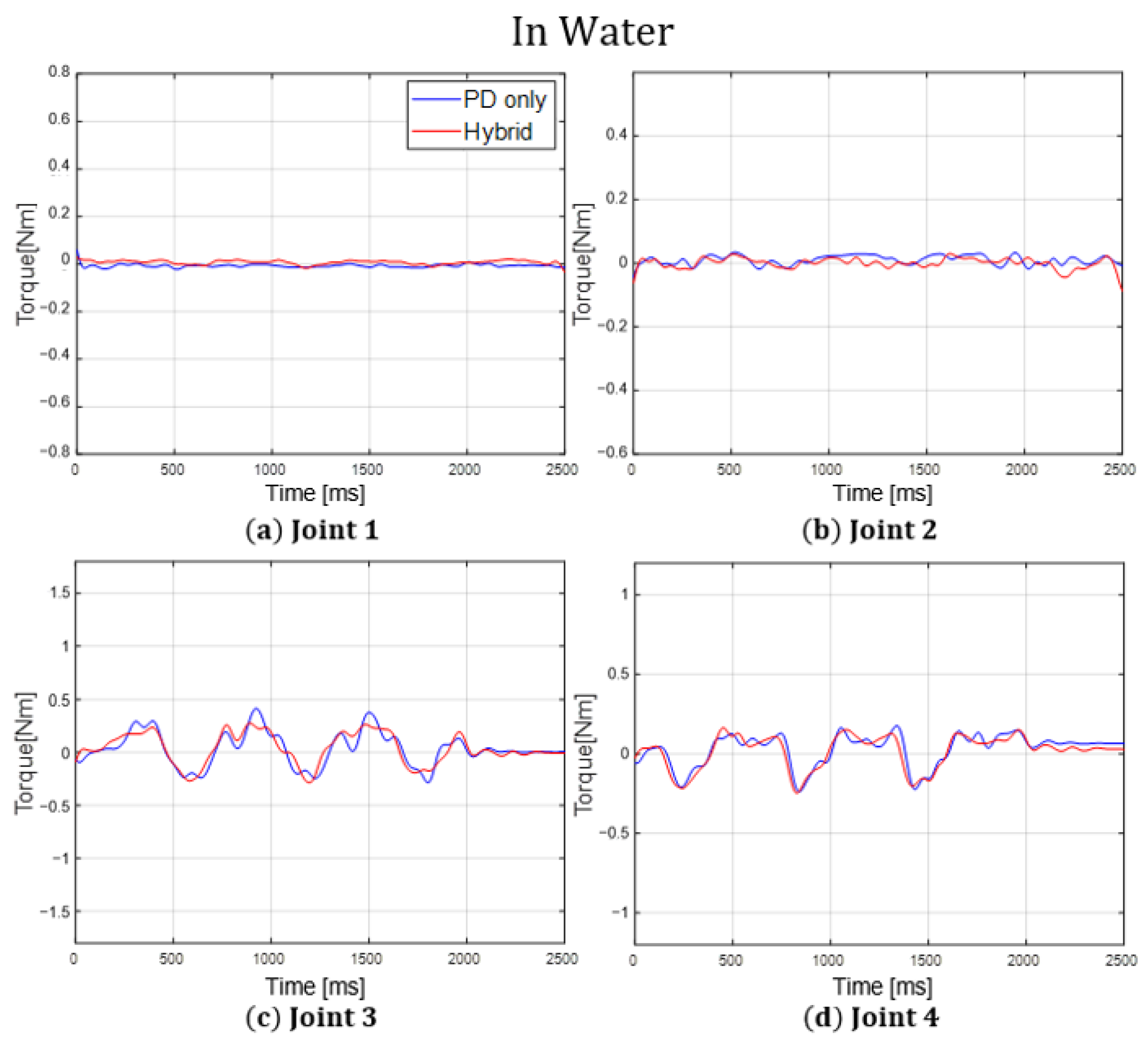
Figure 22 and
Figure 23 represent the torque graphs of each joint for each environment during lateral motion.
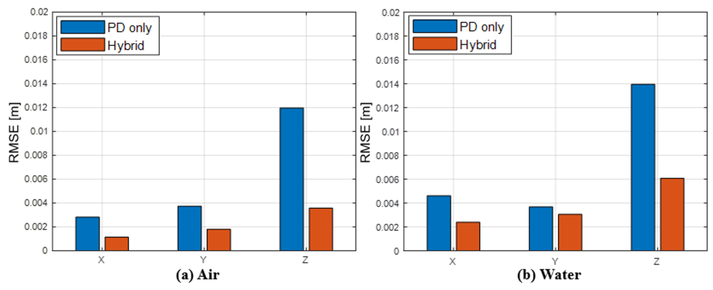
The trajectories of the foot tip graphs facilitate a comparison of the foot tip position accuracy under different control methods and environments. An examination of these graphs reveals that when the hybrid controller is employed, the actual trajectory of the foot tip more closely follows the reference trajectory in both forward and lateral motions. Notably, the position trajectory along the Z-axis with the hybrid controller more accurately follows the reference trajectory.
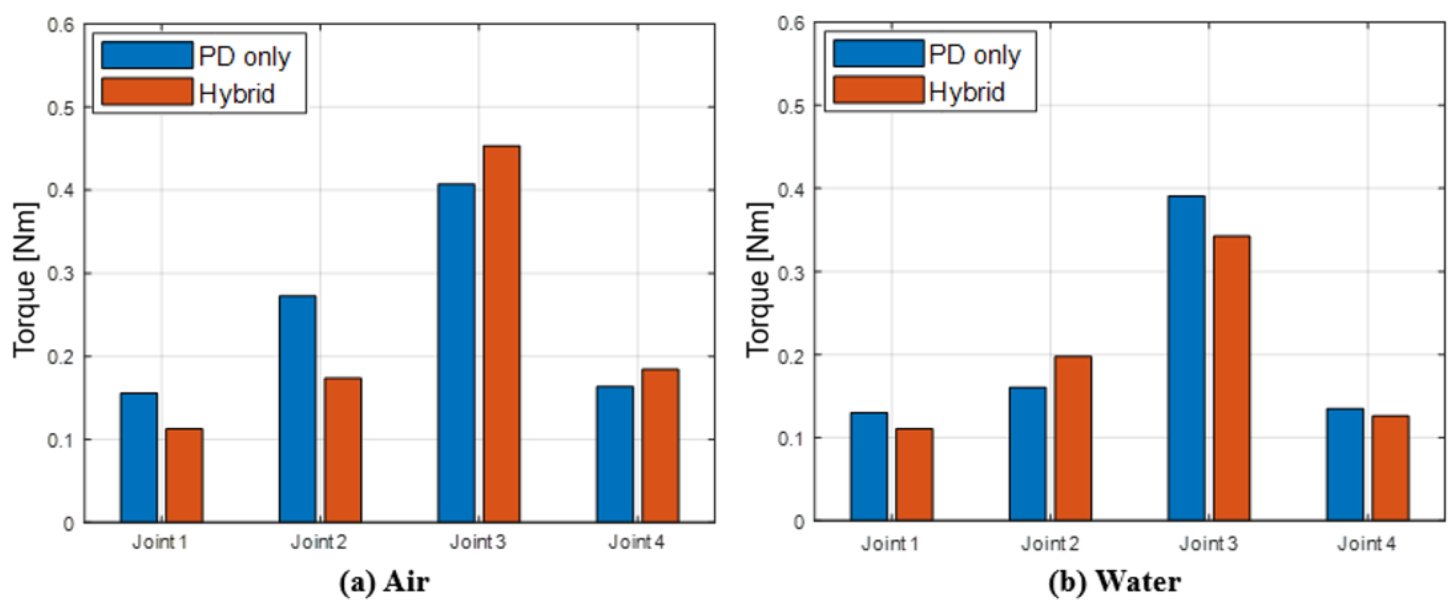
According to the torque graphs, when using the hybrid controller, it is evident that the joint torque does not show much difference compared to a single task-space PD controller, despite achieving higher position accuracy. In particular, the torque trajectories from the hybrid controller are smoother than those from the single task-space PD controller, indicating a higher level of control efficiency with the hybrid method.
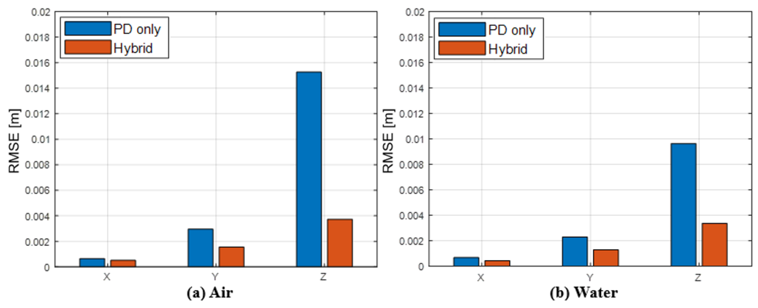
Figure 24 and
Figure 25 represent bar graphs comparing the RMSE for the reference trajectory of the foot tip during lateral motion in air and water, respectively. Correspondingly,
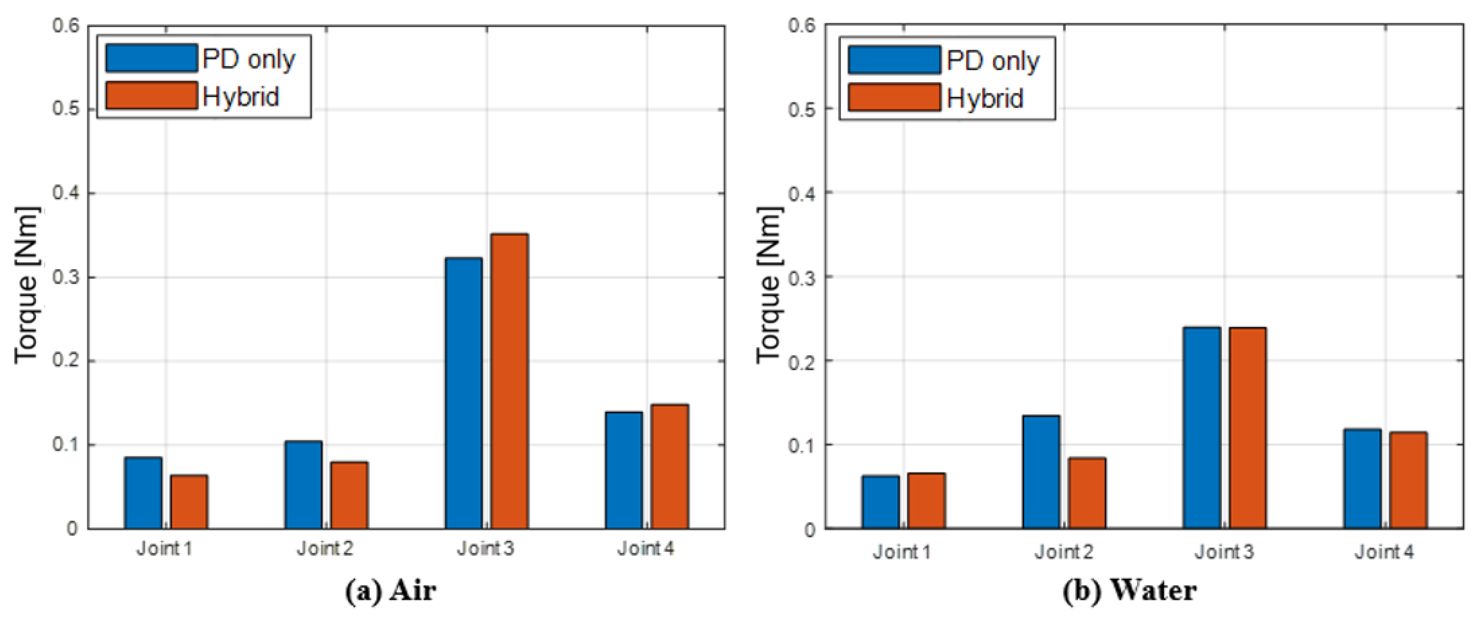
Figure 26 and
Figure 27 represent bar graphs for the RMS torque output in these cases. To facilitate a more accurate comparison, the data from
Figure 24 and
Figure 25 are quantitatively represented in
Table 3, while the data from
Figure 26 and
Figure 27 are represented in
Table 4.
Similarly,
Figure 28 and
Figure 29 depict the RMSE bar graphs for the reference trajectory of the foot tip during forward motion in each environment, and
Figure 30 and
Figure 31 represent bar graphs of the RMS joint torque output for each case. Also, for a more accurate comparison, the data from
Figure 28 and
Figure 29 are quantitatively represented in
Table 5, and the data from
Figure 30 and
Figure 31 are represented in
Table 6.
An analysis of the bar graphs and tables reveals that, across nearly all conditions, the RMSEs for the reference trajectories of the hybrid controller are significantly lower, irrespective of the control gain magnitude. In the case of forward motion with high control gains, the RMSE decreased by approximately 69.96% on the X-axis, 45.07% on the Y-axis, and 68.94% on the Z-axis in air. And in water, the RMSE decreased by about 39.83% on the X-axis, 40.48% on the Y-axis, and 54.07% on the Z-axis.
Additionally, the RMS torque graph shows no significant difference in the joint torque output between the two controllers. The biggest torque difference occurs in the pitch joint during forward motion in the air with high PD control gains, and the difference is approximately 0.1364 Nm, which is at a very small level. This observation indicates that, even with a similar level of torque output, much higher position accuracy was achieved. Furthermore, the RMS joint torque output of each joint increases proportionally with the increase in PD control gains, suggesting a decrease in compliance with disturbance. Therefore, using the hybrid controller can simultaneously satisfy both high position accuracy and joint compliance.
6. Conclusions
In this study, we proposed the hybrid controller to enhance the position-tracking performance of the robot leg. Our approach relies on a deep learning neural network, eliminating the need for explicit modeling and computation of non-linear dynamic characteristics, including fluid effects. The efficacy of the hybrid controller was verified using an actual 4-DOF underwater robot leg. Leveraging the capabilities of deep learning, particularly linear regression, trajectories not directly used for learning were employed for verification. To ensure accurate testing, experiments were conducted with two sets of PD control gains applied to both forward and lateral motions.
The result demonstrated a substantial improvement in position accuracy when comparing the hybrid controller to the single task-space PD controller, even with similar torque outputs across nearly all conditions. Quantitative analysis revealed that the position error in the task-space was reduced by about 60.96% in air and about 42.7% in water on average. These findings suggest the potential of overcoming non-linearity by learning the dynamic characteristics of motors and robots in both air and water. Therefore, this study makes notable contributions by considering non-linear dynamics factors, adapting to various environments, enhancing utility through the combination of PD control, and achieving lower torque output with higher position accuracy.
When controlling the lateral motion of the robot leg, it was observed that the RMSE in water was smaller than that in air, indicating better control performance underwater. This improvement could be attributed to the relatively low fluid force due to the simple movement in the lateral direction motion within a two-dimensional plane. We presumed that buoyancy acted as reduced gravity compensation, likely contributing to the overall enhanced performance. However, in the case of forward-direction motion, it is evident that position-tracking performance was further degraded. For three-dimensional movements like walking, various fluid forces such as drag and lift, in addition to buoyancy, were more generated compared to the two-dimensional movement of the lateral direction motion. This increased complexity seems to have adversely affected control performance. In simpler movements, the influence of non-linear terms may not be significant, allowing even a simple feedback controller to achieve sufficient performance. However, for complex motions such as walking, deterioration in tracking performance may occur because compensating for the effects of fluid becomes challenging, requiring more accurate and sophisticated control methods.
Our proposed hybrid controller utilizes the MLP neural network to consider non-linear dynamic characteristics and incorporates them into position-tracking control in a simplified manner. This method initially poses the challenge of requiring pre-collected data to create a high-performance learning model. Specifically, for underwater data learning, it is necessary to collect underwater motion data first. However, after completing the training model, high-accuracy position tracking control can be performed across various motions and environments without the need for complex operations in each specific case.
The motions used in the verification are based on the motion of a radial-type quadruped walking robot. Therefore, when the ULR depicted in
Figure 1 is deployed later, the learning model can be employed for high position tracking control performance in both air and water environments. Furthermore, additional control methods could be combined with the hybrid controller to maintain performance in more diverse environments, such as tidal current environments.
Author Contributions
Conceptualization, J.-H.B. and J.-Y.K.; methodology, J.-H.B.; software, J.-H.B.; validation, J.-H.B. and J.-Y.K.; formal analysis, J.-H.B.; investigation, J.-H.B.; resources, J.-H.B.; data curation, J.-H.B.; writing—original draft preparation, J.-H.B.; writing—review and editing, J.-Y.K.; visualization, J.-H.B.; supervision, J.-Y.K.; project administration, J.-Y.K.; funding acquisition, J.-Y.K.; All authors have read and agreed to the published version of the manuscript.
Funding
The authors declare that this study received funding from the Civil-Military Technology Cooperation Program of ICMTC, Republic of Korea (Grant number: 21-CM-MU-01, Title: Development of underwater robot for removal of tangled fishing net in propellers). The funder was not involved in the study design, collection, analysis, interpretation of data, the writing of this article, or the decision to submit it for publication.
Institutional Review Board Statement
Not applicable.
Informed Consent Statement
Not applicable.
Data Availability Statement
Data is contained within the article.
Conflicts of Interest
The authors declare no conflicts of interest.
References
- Bellicoso, C.D.; Bjelonic, M.; Wellhausen, L.; Holtmann, K.; Günther, F.; Tranzatto, M.; Fankhauser, P.; Hutter, M. Advances in real-world applications for legged robots. J. Field Robot. 2018, 35, 1311–1326. [Google Scholar] [CrossRef]
- Hooks, J.; Ahn, M.S.; Yu, J.; Zhang, X.; Zhu, T.; Chae, H.; Hong, D. Alphred: A multi-modal operations quadruped robot for package delivery applications. IEEE Robot. Autom. Lett. 2020, 5, 5409–5416. [Google Scholar] [CrossRef]
- Chen, Z.; Fan, T.; Zhao, X.; Liang, J.; Shen, C.; Chen, H.; Manocha, D.; Pan, J.; Zhang, W. Autonomous social distancing in urban environments using a quadruped robot. IEEE Access 2021, 9, 8392–8403. [Google Scholar] [CrossRef]
- Lee, J.; Hwangbo, J.; Wellhausen, L.; Koltun, V.; Hutter, M. Learning quadrupedal locomotion over challenging terrain. Sci. Robot. 2020, 5, eabc5986. [Google Scholar] [CrossRef] [PubMed]
- Kumar, A.; Fu, Z.; Pathak, D.; Malik, J. Rma: Rapid motor adaptation for legged robots. arXiv 2021, arXiv:2107.04034. [Google Scholar] [CrossRef]
- Cheng, X.; Shi, K.; Agarwal, A.; Pathak, D. Extreme Parkour with Legged Robots. arXiv 2023, arXiv:2309.14341. [Google Scholar]
- Cieslak, P.; Ridao, P.; Giergiel, M. Autonomous underwater panel operation by GIRONA500 UVMS: A practical approach to autonomous underwater manipulation. In Proceedings of the 2015 IEEE International Conference on Robotics and Automation (ICRA), Seattle, WA, USA, 26–30 May 2015; IEEE: Piscataway, NJ, USA, 2015; pp. 529–536. [Google Scholar]
- Aguirre-Castro, O.A.; Inzunza-González, E.; García-Guerrero, E.E.; Tlelo-Cuautle, E.; López-Bonilla, O.R.; Olguín-Tiznado, J.E.; Cárdenas-Valdez, J.R. Design and Construction of an ROV for Underwater Exploration. Sensors 2019, 19, 5387. [Google Scholar] [CrossRef] [PubMed]
- Kabanov, A.; Kramar, V.; Ermakov, I. Design and modeling of an experimental rov with six degrees of freedom. Drones 2021, 5, 113. [Google Scholar] [CrossRef]
- Kang, H.; Shim, H.; Jun, B.H.; Lee, P.M. Development of a specialized underwater leg convertible to a manipulator for the seabed walking robot cr200. J. Inst. Control Robot. Syst. 2013, 19, 709–717. [Google Scholar] [CrossRef]
- Picardi, G.; Chellapurath, M.; Iacoponi, S.; Stefanni, S.; Laschi, C.; Calisti, M. Bioinspired underwater legged robot for seabed exploration with low environmental disturbance. Sci. Robot. 2020, 5, eaaz1012. [Google Scholar] [CrossRef] [PubMed]
- Picardi, G.; Astolfi, A.; Chatzievangelou, D.; Aguzzi, J.; Calisti, M. Underwater legged robotics: Review and perspectives. Bioinspiration Biomim. 2023, 18, 031001. [Google Scholar] [CrossRef] [PubMed]
- Jun, B.H.; Shim, H.W.; Lee, P.M. Approximated generalized torques by the hydrodynamic forces acting on legs of an underwater walking robot. Int. J. Ocean Syst. Eng. 2011, 1, 222–229. [Google Scholar] [CrossRef]
- Zarebidoki, M.; Dhupia, J.S.; Xu, W. Hydrodynamics Simulation and Analysis of an Underwater Manipulator. In Proceedings of the 2021 27th International Conference on Mechatronics and Machine Vision in Practice (M2VIP), Shanghai, China, 26–28 November 2021; IEEE: Piscataway, NJ, USA, 2021; pp. 394–399. [Google Scholar]
- Zhong, J.; Gao, C.; Tian, Y.; Zhang, M. Research on the Influence of Hydrodynamic Analysis to Dynamic Modeling of Underwater Manipulator. In Proceedings of the 2023 IEEE 6th Information Technology, Networking, Electronic and Automation Control Conference (ITNEC), Chongqing, China, 24–26 February 2023; IEEE: Piscataway, NJ, USA, 2023; Volume 6, pp. 982–986. [Google Scholar]
- Yao, J.; Wang, C. Model reference adaptive control for a hydraulic underwater manipulator. J. Vib. Control 2012, 18, 893–902. [Google Scholar] [CrossRef]
- Wang, Z.; Lin, M.; Ban, C. Research on hydrodynamics analysis and double loop integral sliding mode control of 4-joint underwater manipulator. In Proceedings of the 2017 14th International Conference on Ubiquitous Robots and Ambient Intelligence (URAI), Jeju, Republic of Korea, 28 June–1 July 2017; IEEE: Piscataway, NJ, USA, 2017; pp. 728–733. [Google Scholar]
- Sagara, S.; Ambar, R. Performance comparison of control methods using a dual-arm underwater robot-Computed torque based control and resolved acceleration control for UVMS. In Proceedings of the 2020 IEEE/SICE International Symposium on System Integration (SII), Honolulu, HI, USA, 12–15 January 2020; IEEE: Piscataway, NJ, USA, 2020; pp. 1094–1099. [Google Scholar]
- Dai, Y.; Wu, D.; Yu, S.; Yan, Y. Robust control of underwater vehicle-manipulator system using grey wolf optimizer-based nonlinear disturbance observer and H-infinity controller. Complexity 2020, 2020, 6549572. [Google Scholar] [CrossRef]
- Zhou, S.; Shen, C.; Xia, Y.; Chen, Z.; Zhu, S. Adaptive robust control design for underwater multi-dof hydraulic manipulator. Ocean Eng. 2022, 248, 110822. [Google Scholar] [CrossRef]
- Wang, S.; Chaovalitwongse, W.; Babuska, R. Machine learning algorithms in bipedal robot control. IEEE Trans. Syst. Man Cybern. Part C Appl. Rev. 2012, 42, 728–743. [Google Scholar] [CrossRef]
- Bhattacharya, S.; Dutta, S.; Maiti, T.K.; Miura-Mattausch, M.; Navarro, D.; Mattausch, H.J. Machine learning algorithm for autonomous control of walking robot. In Proceedings of the 2018 International Symposium on Devices, Circuits and Systems (ISDCS), Howrah, India, 29–31 March 2018; IEEE: Piscataway, NJ, USA, 2018; pp. 1–4. [Google Scholar]
- Polydoros, A.S.; Nalpantidis, L.; Krüger, V. Real-time deep learning of robotic manipulator inverse dynamics. In Proceedings of the 2015 IEEE/RSJ International Conference on Intelligent Robots and Systems (IROS), Hamburg, Germany, 28 September–2 October 2015; IEEE: Piscataway, NJ, USA, 2015; pp. 3442–3448. [Google Scholar]
- Jinhyeok, B.; Jung-Yup, K. Position Tracking Control of 4-DOF Underwater Robot Leg Using Deep Learning. 2023. Available online: https://www.youtube.com/watch?v=Hcc5VUAYX3A (accessed on 1 December 2023).
Figure 1.
Radial-type quadruped ULR trying to remove fishing net tangled in a propeller.
Figure 1.
Radial-type quadruped ULR trying to remove fishing net tangled in a propeller.
Figure 2.
Experiment of 4-DOF underwater robot leg moving underwater [
24].
Figure 2.
Experiment of 4-DOF underwater robot leg moving underwater [
24].
Figure 3.
Joint configuration of the robot leg.
Figure 3.
Joint configuration of the robot leg.
Figure 4.
Control system diagram.
Figure 4.
Control system diagram.
Figure 5.
Reference foot tip trajectory.
Figure 5.
Reference foot tip trajectory.
Figure 6.
MLP neural network.
Figure 6.
MLP neural network.
Figure 7.
Hybrid control diagram.
Figure 7.
Hybrid control diagram.
Figure 8.
Reference foot tip trajectory of forward motion for evaluation.
Figure 8.
Reference foot tip trajectory of forward motion for evaluation.
Figure 9.
Reference foot tip trajectory of lateral motion for evaluation.
Figure 9.
Reference foot tip trajectory of lateral motion for evaluation.
Figure 10.
Snapshots of the forward motion control in air and underwater environments.
Figure 10.
Snapshots of the forward motion control in air and underwater environments.
Figure 11.
Snapshots of the lateral motion control in air and underwater environments.
Figure 11.
Snapshots of the lateral motion control in air and underwater environments.
Figure 12.
Position trajectories of the foot tip for forward motion with high PD gain in air.
Figure 12.
Position trajectories of the foot tip for forward motion with high PD gain in air.
Figure 13.
Position paths of the foot tip for forward motion with high PD gain in air.
Figure 13.
Position paths of the foot tip for forward motion with high PD gain in air.
Figure 14.
Position trajectories of the foot tip for forward motion with high PD gain in water.
Figure 14.
Position trajectories of the foot tip for forward motion with high PD gain in water.
Figure 15.
Position paths of the foot tip for forward motion with high PD gain in water.
Figure 15.
Position paths of the foot tip for forward motion with high PD gain in water.
Figure 16.
Torque output of each joint of forward motion with high PD gain in air.
Figure 16.
Torque output of each joint of forward motion with high PD gain in air.
Figure 17.
Torque output of each joint of forward motion with high PD gain in water.
Figure 17.
Torque output of each joint of forward motion with high PD gain in water.
Figure 18.
Position trajectories of the foot for lateral motion with high PD gain in air.
Figure 18.
Position trajectories of the foot for lateral motion with high PD gain in air.
Figure 19.
Position paths of the foot for lateral motion with high PD gain in air.
Figure 19.
Position paths of the foot for lateral motion with high PD gain in air.
Figure 20.
Position trajectories of the foot for lateral motion with high PD gain in water.
Figure 20.
Position trajectories of the foot for lateral motion with high PD gain in water.
Figure 21.
Position paths of the foot for lateral motion with high PD gain in water.
Figure 21.
Position paths of the foot for lateral motion with high PD gain in water.
Figure 22.
Torque output of each joint of lateral motion with high PD gain in air.
Figure 22.
Torque output of each joint of lateral motion with high PD gain in air.
Figure 23.
Torque output of each joint of lateral motion with high PD gain in water.
Figure 23.
Torque output of each joint of lateral motion with high PD gain in water.
Figure 24.
RMSE of lateral motion with low PD gain.
Figure 24.
RMSE of lateral motion with low PD gain.
Figure 25.
RMSE of lateral motion with high PD gain.
Figure 25.
RMSE of lateral motion with high PD gain.
Figure 26.
RMS torque output of lateral motion with low PD gain.
Figure 26.
RMS torque output of lateral motion with low PD gain.
Figure 27.
RMS torque output of lateral motion with high PD gain.
Figure 27.
RMS torque output of lateral motion with high PD gain.
Figure 28.
RMSE of forward motion with low PD gain.
Figure 28.
RMSE of forward motion with low PD gain.
Figure 29.
RMSE of forward motion with high PD gain.
Figure 29.
RMSE of forward motion with high PD gain.
Figure 30.
RMS torque output of forward motion with low PD gain.
Figure 30.
RMS torque output of forward motion with low PD gain.
Figure 31.
RMS torque output of forward motion with high PD gain.
Figure 31.
RMS torque output of forward motion with high PD gain.
Table 1.
Specifications of the robot leg.
Table 1.
Specifications of the robot leg.
| Parameter | Value |
|---|
| Weight |
|
| Dimensions |
|
| D.O.F. | 4 |
| Sensors | Encoder 4 ea. |
| Material | Onyx (micro carbon fiber) |
| Main Controller | UP Squared board |
Table 2.
Specifications of XW540-T140, water-proof motor.
Table 2.
Specifications of XW540-T140, water-proof motor.
| Parameter | Value |
|---|
| Input Voltage | |
| Stall Torque | |
| Stall Current | |
| Weight | |
| Gear Ratio | |
| Operating Temperature | |
Table 3.
RMSE of lateral motion. (unit: [m]).
Table 3.
RMSE of lateral motion. (unit: [m]).
| Env. | PD Gain | Method | X | Y | Z |
|---|
| Air | Low | PD only | 0.0006 | 0.0030 | 0.0153 |
| Hybrid | 0.0005 * | 0.0016 * | 0.0037 * |
| High | PD only | 0.0017 | 0.0024 | 0.0102 |
| Hybrid * | 0.0013 * | 0.0018 * | 0.0027 * |
| Water | Low | PD only | 0.0006 | 0.0023 | 0.0096 |
| Hybrid | 0.0004 * | 0.0013 * | 0.0034 * |
| High | PD only | 0.0003 * | 0.0019 | 0.0060 |
| Hybrid | 0.0004 | 0.0012 * | 0.0020 * |
Table 4.
RMS joint torque of lateral motion. (unit: [Nm]).
Table 4.
RMS joint torque of lateral motion. (unit: [Nm]).
| Env. | PD Gain | Method | Joint 1 | Joint 2 | Joint 3 | Joint 4 |
|---|
| Air | Low | PD only | 0.0852 | 0.1042 | 0.3226 * | 0.1391 * |
| Hybrid | 0.0637 * | 0.0794 * | 0.3516 | 0.1484 |
| High | PD only | 0.1556 | 0.2725 | 0.4072 * | 0.1635 * |
| Hybrid | 0.1127 * | 0.1735 * | 0.4533 | 0.1843 |
| Water | Low | PD only | 0.0625 * | 0.1343 | 0.2394 | 0.1181 |
| Hybrid | 0.0659 | 0.0837 * | 0.2386 * | 0.1142 * |
| High | PD only | 0.1300 | 0.1602 * | 0.3905 | 0.1349 |
| Hybrid | 0.1107 * | 0.1975 | 0.3422 * | 0.1259 * |
Table 5.
RMSE of forward motion. (unit: [m]).
Table 5.
RMSE of forward motion. (unit: [m]).
| Env. | PD Gain | Method | X | Y | Z |
|---|
| Air | Low | PD only | 0.0030 | 0.0044 | 0.0150 |
| Hybrid | 0.0009 * | 0.0024 * | 0.0047 * |
| High | PD only | 0.0028 | 0.0037 | 0.0120 |
| Hybrid | 0.0011 * | 0.0018 * | 0.0036 * |
| Water | Low | PD only | 0.0058 | 0.0051 | 0.0174 |
| Hybrid | 0.0035 * | 0.0031 * | 0.0080 * |
| High | PD only | 0.0046 | 0.0037 | 0.0139 |
| Hybrid | 0.0024 * | 0.0030 * | 0.0061 * |
Table 6.
RMS joint torque of forward motion. (unit: [Nm]).
Table 6.
RMS joint torque of forward motion. (unit: [Nm]).
| Env. | PD Gain | Method | Joint 1 | Joint 2 | Joint 3 | Joint 4 |
|---|
| Air | Low | PD only | 0.1797 * | 0.1300 | 0.4039 * | 0.1611 * |
| Hybrid | 0.1945 | 0.1287 * | 0.4375 | 0.1678 |
| High | PD only | 0.2532 * | 0.4075 | 0.4525 * | 0.1806 |
| Hybrid | 0.2636 | 0.2711 * | 0.4773 | 0.1606 * |
| Water | Low | PD only | 0.2583 * | 0.1803 * | 0.5089 * | 0.3429 |
| Hybrid | 0.2871 | 0.1912 | 0.5216 | 0.2893 * |
| High | PD only | 0.2907 * | 0.2610 | 0.5286 * | 0.3098 |
| Hybrid | 0.3276 | 0.1699 * | 0.5781 | 0.3021 * |
| Disclaimer/Publisher’s Note: The statements, opinions and data contained in all publications are solely those of the individual author(s) and contributor(s) and not of MDPI and/or the editor(s). MDPI and/or the editor(s) disclaim responsibility for any injury to people or property resulting from any ideas, methods, instructions or products referred to in the content. |
© 2024 by the authors. Licensee MDPI, Basel, Switzerland. This article is an open access article distributed under the terms and conditions of the Creative Commons Attribution (CC BY) license (https://creativecommons.org/licenses/by/4.0/).


