Article

Unified Elasto-Plastic Solution for High-Speed Railway Tunnel in Cold Regions Considering Dual Transverse Isotropic Model of Frozen Rock Mass

1
Tunnel and Underground Engineering Research Center of Ministry of Education, Beijing Jiaotong University, Beijing 100044, China
2
Railway Engineering Research Institute, China Academy of Railway Sciences Corporation Limited, Beijing 100081, China
*
Author to whom correspondence should be addressed.
Appl. Sci. 2024, 14(24), 11796; https://doi.org/10.3390/app142411796
Submission received: 9 October 2024 / Revised: 5 December 2024 / Accepted: 13 December 2024 / Published: 17 December 2024

Abstract

:
Frost damage is one of the main influencing factors for the deterioration of support structures in cold-region tunnels. A new dual transverse isotropic model of frozen rock mass is first proposed based on parameter strain and elastic modulus to serve as the theoretical basis for tunnel operation safety in cold regions. Subsequently, a unified elasto-plastic solution for high-speed railway tunnels in cold regions is derived based on the new dual transverse isotropic model, and the accuracy of the analytical solution is verified by comparisons with existing models and experimental results. Finally, the effect of the model parameters on stress and displacement is explored. The results reveal a significant negative correlation between the plastic radius of the frozen rock mass zone and the pressure acting on the inner surface of the support structure, the influence coefficient of intermediate principal stress, radial-gradient influence coefficient of the frozen rock mass, and anisotropic frost heave coefficient of the frozen rock mass, as well as between the frost-heaving force and the influence coefficient of intermediate principal stress parameter. However, the frost-heaving force is positively correlated with the pressure acting on the inner surface of the support structure, the radial gradient influence coefficient of the frozen rock mass, and the anisotropic frost heave coefficients of the frozen rock mass. Therefore, the pressure acting on the inner surface of the support structure, the radial gradient influence co-efficient of the frozen rock mass, and the anisotropic frost heave coefficients of frozen rock mass should be reasonably considered, but the strength theory of the surrounding rock should be strongly considered in the design of tunnel structures in cold regions.

1. Introduction

Following the implementation of the “Strong Transportation Country” and “West Development” strategies, the density of the transportation network in China is expected to increase. Hence, new highway and railway tunnels will be designed, constructed, and operated in the cold regions of western and northeastern China. Cold-region tunnels are primarily characterized by the frost-heaving force, which differs from that in typical tunnels. On-site surveys have shown that the frost heave force is one of the important external factors causing damage to tunnel structures in cold regions [1,2], as shown in Figure 1. Therefore, studying the frost-heaving force has important scientific value and engineering significance in cold-region tunnels.
Based on the elastic solution of the frost-heaving force, a visco-elastic solution was obtained by combining the corresponding principle and the Laplace transform. The analytical results indicated that the frost-heaving force was an important influencing factor. If the frost-heaving force was considered, the stress of the lining structure was higher than that when the frost-heaving force was ignored [1]. The Mohr–Coulomb yield criterion, as one of the classic yield criteria, is widely used in the derivation of plastic solutions. The elasto-plastic solution meets the Mohr–Coulomb yield criterion, revealing that the frost heave was also an important factor during the development of plastic zones, and the frost heave will promote the expansion of the plastic zone range [3,4]. Subsequently, the non-uniform frost heave was further considered, and the analytical solution was established. The analysis results demonstrated that the stress difference in the support structure increases when frost heave is considered [5].
For the saturated rock, the frost heave behavior was systematically studied by conducting a series of model experiments. The results demonstrated that the frost heave behavior is more significant in the parallel freezing direction than in the vertical direction. A transversely isotropic frost-heaving model was then presented based on the experimental results, and the anisotropic frost heave coefficient was proposed and defined [6]. Additionally, by combining different yield criteria and non-associated flow rules, the plastic behavior of the frost heave that considers transversely isotropic frost heave was explored [7,8,9]. The analytical results revealed that the frost-heaving force increases with the increase in the frost heave coefficient, which indicates that the effect of transverse isotropy of the freezing rock mass on the frost-heaving force is significant [10]. In addition, mechanical models for composite lining structures [11] and dual non-uniform frost-heaving for the case of frozen rock mass [12] were proposed, solved, and analyzed. Compared to hydrostatic stress, non-hydrostatic stress more realistically reflects engineering practice. Accordingly, elastic analytical solutions of circumferential and radial stresses and radial displacement for rock mass and structure have been proposed [13], and the influence of the construction time of the structure on the stress and displacement has been explored [14]. The results showed that the influence of the lateral pressure coefficient on the vertical direction was slighter.
However, existing solutions mainly consider the transversely isotropic characteristic of the frozen rock mass but neglect the impact of the radial temperature gradient on the mechanical properties of the frozen rock mass. The literature indicates that the lowest temperature zone is located on the inner surface of the frozen rock mass, and the temperature increases with the increase in the radial depth of the surrounding rock [15,16]. Cyclic freeze–thaw action increasingly damages surrounding rock with the increase in the temperature difference. Hence, the mechanical properties of frozen rock mass deteriorate with increasing depth along the radial direction [17,18]. However, the mechanical properties of the frozen rock mass along the radial direction in existing analytical models were assumed constant, which is inconsistent with actual engineering practice.
Therefore, this study proposes a dual transverse isotropic model of frozen rock mass, considering the variation in mechanical properties along the radial direction and the transversely isotropic characteristic of the frozen rock mass. Subsequently, an elasto-plastic solution for high-speed railway tunnels in cold regions is obtained based on the dual transverse isotropic model of the frozen rock mass. The accuracy of the proposed mechanical model is verified by comparisons with existing solutions and experimental results. Finally, the sensitivity analysis of analytical solution parameters is further explored.

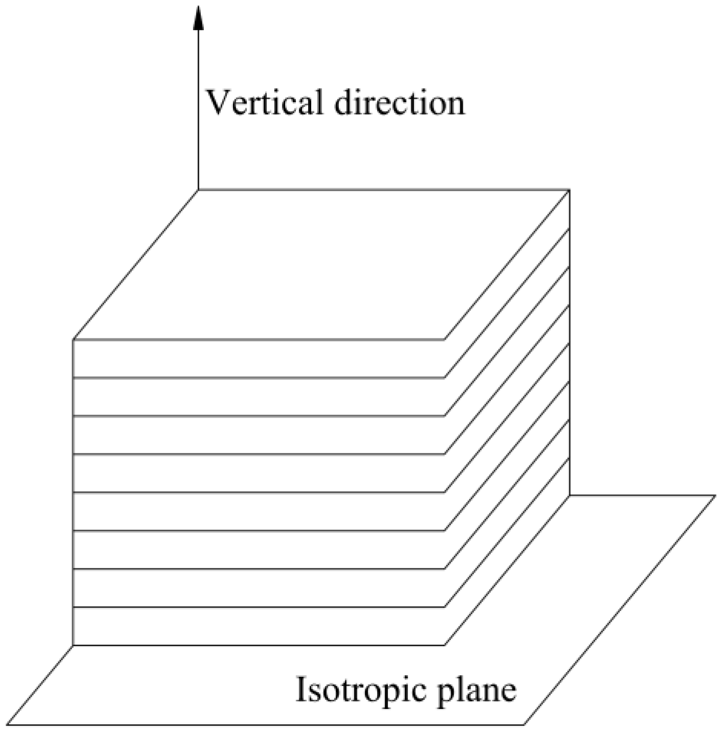
2. Dual Transverse Isotropic Model of Frozen Rock Mass

A plane in which the properties of the rock in different directions are identical is called an isotropic plane. When the properties of the rock perpendicular to the isotropic plane are different from those within the isotropic plane, this rock is referred to as transversely isotropic [19,20], as shown in Figure 2. Accordingly, such rock is an isotropic material.
In cold regions, the longitudinal and circumferential temperature gradient is largely invisible, and the radial temperature gradient is prominent in tunnel engineering. On-site monitoring data from cold-region tunnels [21] also demonstrated that the measured temperature gradient is positively correlated with the radial direction of the tunnel, as shown in Figure 3. Hence, the frozen rock mass can be regarded as a transversely isotropic material. Subsequently, the strain was used as an indicator of the transverse isotropy of the frozen rock mass, and the corresponding expressions [6] are
ε r = k k + 2 ε v ε θ = ε l = 1 k + 2 ε v
where ε represents strain. The subscripts r, θ, and l represent the radial, circumferential, and longitudinal directions, respectively. Parameters k and εv represent the anisotropic frost heave coefficients and volumetric strain, respectively. If k = 1 is assumed, the expressions can be simplified as the isotropy case.
The periodic freezing and thawing caused by the alternation of winter and summer significantly weaken the bearing capacity of the rock mass, which is composed of solid, liquid, and gas materials. Weakening is mainly the result of the additional expansion pressure exerted by the increases in volume as water freezes, which internally damages the rock mass, as shown in Figure 4. Typically, a decrease in elastic modulus can indicate that the surrounding rock has been damaged. The larger the temperature difference, the greater the elastic modulus decreases. Therefore, similar to the temperature gradient, the elastic modulus increases with the increase in the radial depth of the surrounding rock. The elastic modulus becomes constant when the depth reaches the unfrozen rock mass boundary. The increase in the elastic modulus with depth along the radial direction is assumed to be a power-law function [22,23], and the formula is as follows:
E f ( r ) = E uf ( r R uf ) α f
where E represents elastic modulus; subscripts f and uf represent the frozen and unfrozen rock mass, respectively; r represents the distance from the tunnel center in the radial direction; Ruf represents the depth of the frozen rock mass; and αf represents the radial gradient influence coefficient of the frozen rock mass. If αf = 0 is assumed, the expression can also be simplified as an isotropy case.
In summary, a dual transverse isotropic model of frozen rock mass was proposed based on the strain and elastic modulus parameters. If the parameter values are reasonable (e.g., k = 1 and αf = 0), the dual transverse isotropic model can be simplified as an isotropy case. Subsequently, the mechanical model of the cold-region tunnel is established and further solved by considering the dual transverse isotropy of frozen rock mass.

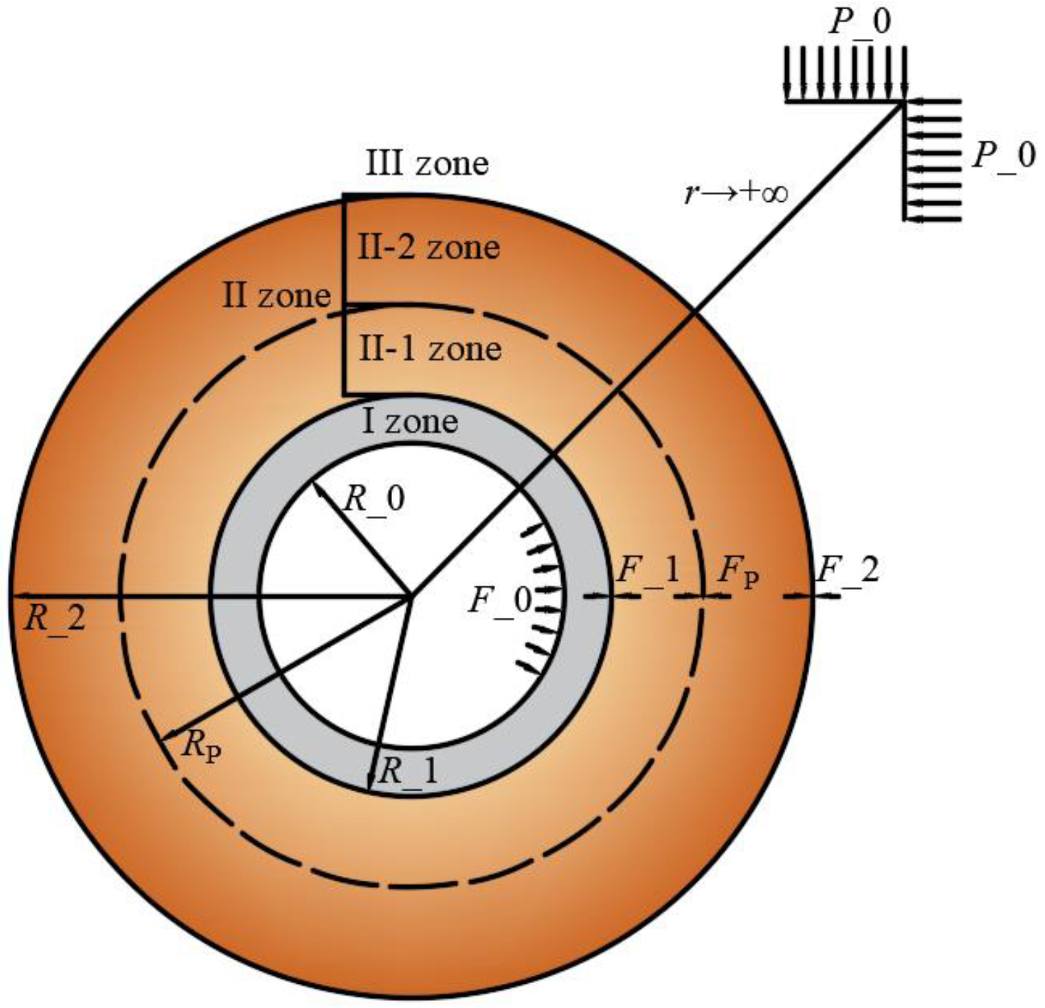
3. Establishing of Mechanical Model

Figure 5 shows a sketch of the mechanical model of the surrounding rock and lining structure of a cold-region tunnel. Zone I represents the lining structure. Zone II and III represent the frozen and unfrozen rock mass, respectively. Zone II is further subdivided into II-1 and II-2, which represent the plastic and elastic rock mass, respectively. As zone II freezes and expands, additional pressure is exerted on the lining structure due to the limitations of zone I and III, which is referred to as the frost heave force [10,12,13]. As shown in Figure 5, R_0 and R_1 represent the inner and outer radius of the lining structure, respectively. R_2 and represent the outer radius of the frozen rock mass. RP represents the radius of the yield range of frozen rock mass. In addition, P_0 represents the far-field pressure in the tunnel situ. F_0 represents external pressure, such as aerodynamic force [8]. F_1 and F_2 represent internal pressure induced by freezes and expands of the frozen rock mass. RP represents internal pressure acting on the contact surface between plastic and elastic rock mass.
The following basic assumptions were adopted to solve the mechanical model: (1) The cross-sectional shape of a deeply buried tunnel is circular. (2) Zone I and zone III are isotropic, homogeneous, and elastic media, and zone II is a transversely isotropic homogeneous elasto-plastic medium. (3) Zone II satisfies the unified strength theory [24,25]. (4) The plane strain condition is employed. (5) The body forces of the rock mass and structure are ignored.
In the circumferential and radial stresses of zones I, II, and III, the equilibrium equation satisfied can be given as follows:
d σ r i d r + σ r i σ θ i r = 0
where σ represents the stress. Superscript i represents the zone number (e.g., I = I, II, II-1, II-2, and III).
The geometric equations satisfied by the circumferential and radial strains of zones I, II, and III can be given as follows:
ε r i = d u r i d r ε θ i = u r i r
where u represents displacement.
The constitutive equations satisfied by zone I can be given as follows:
ε r I = 1 μ s 2 E s ( σ r I μ s 1 μ s σ θ I ) ε θ I = 1 μ s 2 E s ( σ θ I μ s 1 μ s σ r I )
where μ represents Poisson’s ratio and subscript s represents support zone I.
The constitutive equations [5,8] satisfied by zone II can be given as follows:
ε r IIe = 1 μ f 2 E f ( r ) ( ( σ r IIe P _ 0 ) μ f 1 μ f ( σ θ IIe P _ 0 ) ) C 1 ε θ IIe = 1 μ f 2 E f ( r ) ( ( σ θ IIe P _ 0 ) μ f 1 μ f ( σ r IIe P _ 0 ) ) C 2 C 1 = ( k f k f + 2 ε v + μ f 1 k + 2 ε v ) C 2 = ( 1 k f + 2 ε v + μ f k f k f + 2 ε v )
where superscript e represents the elasticity in zone II.
The constitutive equations [7,22] satisfied by zone III can be given as follows:
ε r III = 1 μ uf 2 E uf ( ( σ r III P _ 0 ) μ uf 1 μ uf ( σ θ III P _ 0 ) ) ε θ III = 1 μ uf 2 E uf ( ( σ θ III P _ 0 ) μ uf 1 μ uf ( σ r III P _ 0 ) )
The expression of the unified strength theory can be written as follows:
σ θ = A σ r + B
where A and B represent the unified strength theory parameters, and the corresponding expressions are
A = ( 2 + b r ) + ( 2 + 3 b r ) sin φ ( 2 + b r ) ( 1 sin φ ) B = 4 ( 1 + b r ) c cos φ ( 2 + b r ) ( 1 sin φ )
where br represents the influence coefficient of intermediate principal stress and c and φ represent cohesion and internal friction angle, respectively. If br = 0.0 and br = 1.0 are assumed, respectively, the unified strength theory can degraded into the Mohr–Coulomb and twin-shear criterion, respectively [26].

4. Solution of Mechanical Model

4.1. Mechanical Analysis of Zone I

The stress boundary conditions in zone I can be given as follows:
σ r I = F _ 0 r = R _ 0 σ r I = F _ 1 r = R _ 1
By combining the boundary conditions and the Lame solutions, the stress solutions can be obtained:
σ r I = 1 R _ 1 2 / r 2 1 R _ 1 2 / R _ 0 2 F _ 0 + 1 R _ 0 2 / r 2 1 R _ 0 2 / R _ 1 2 F _ 1 σ θ I = 1 + R _ 1 2 / r 2 1 R _ 1 2 / R _ 0 2 F _ 0 + 1 + R _ 0 2 / r 2 1 R _ 0 2 / R _ 1 2 F _ 1
The displacement solution can be obtained by substituting Equations (11) and (5) into Equation (4):
u r I = F _ 0 ( 1 2 μ s + R _ 1 2 / r 2 ) ( 1 + μ s ) E s ( 1 R _ 1 2 / R _ 0 2 ) r + F _ 1 ( 1 2 μ s + R _ 0 2 / r 2 ) ( 1 + μ s ) E s ( 1 R _ 0 2 / R _ 1 2 ) r

4.2. Mechanical Analysis of Zone II-1

The stress boundary conditions in zone II-1 can be given as follows:
σ r II - 1 = F _ 1   r = R _ 1 σ r II - 1 = F P r = R P
By combining the equilibrium equation and the unified strength theory, the stress solutions can be obtained:
σ r II - 1 = D r A 1 + B 1 A σ θ II - 1 = A σ r II - 1 + B
where D is an integral constant related to the boundary conditions.
The value of D can be determined from the boundary conditions of Equation (13), and the stress solutions can be rewritten as follows:
σ r II - 1 = ( F _ 1 B 1 A ) r A 1 R _ 1 A 1 + B 1 A σ θ II - 1 = A ( F _ 1 B 1 A ) r A 1 R _ 1 A 1 + B 1 A
The strain in zone II-1 can be decomposed into elastic and plastic strains, and the expression is as follows:
ε r II - 1 = ε r II - 1 e + ε r II - 1 p ε θ II - 1 = ε θ II - 1 e + ε θ II - 1 p
where superscript p represents the plasticity in zone II-1.
The strain compatibility equation satisfied by zone II-1 can be given as
d ε θ II - 1 d r = ε r II - 1 ε θ II - 1 r
The expression of the non-associated flow rule [27,28,29] for plastic strain in zone II-1 is
ε r II - 1 p + β ε θ II - 1 p = 0
where β represents the characteristic parameters related to shear expansion.
After substituting Equations (16) and (18) into Equation (17), Equation (17) can be rewritten as follows:
d ε θ II - 1 p d r + ( β + 1 ) ε θ II - 1 p r = d ε θ II - 1 e d r + ε r II - 1 e ε θ II - 1 e r
The corresponding boundary condition for plastic strain [30] in zone II-1 is
ε θ II - 1 p = 0 r = R P
The elastic strain solutions in zone II-1 can be obtained by substituting Equation (15) into Equation (6):
ε r II - 1 e = ( 1 μ f A μ f ) ( 1 + μ f ) E f 0 ( r / R _ 2 ) α r A 1 R _ 1 A 1 ( F _ 1 B 1 A ) + ( 1 2 μ f ) ( 1 + μ f ) E f 0 ( r / R _ 2 ) α B 1 A ( 1 2 μ f ) ( 1 + μ f ) E f 0 ( r / R _ 2 ) α P _ 0 C 1 ε θ II - 1 e = ( A A μ f μ f ) ( 1 + μ f ) E f 0 ( r / R _ 2 ) α r A 1 R _ 1 A 1 ( F _ 1 B 1 A ) + ( 1 2 μ f ) ( 1 + μ f ) E f 0 ( r / R _ 2 ) α B 1 A ( 1 2 μ f ) ( 1 + μ f ) E f 0 ( r / R _ 2 ) α P _ 0 C 2
Equation (19) can be solved after substituting Equation (21) into Equation (19):
ε θ II - 1 p = Q r 1 + β ( A A μ f μ f ) ( 1 + μ f ) E f 0 R _ 1 A 1 ( A + β α f ) ( F _ 1 B 1 A ) A 1 α f ( 1 / R _ 2 ) α f r A 1 α f   ( A 1 ) ( 1 + μ f ) E f 0 R _ 1 A 1 ( A + β α f ) ( F _ 1 B 1 A ) 1 ( 1 / R _ 2 ) α f r A 1 α f   ( 1 2 μ f ) ( 1 + μ f ) E f 0 ( α f + β + 1 ) B 1 A α f ( 1 / R _ 2 ) α f r α f   + P _ 0 ( 1 2 μ f ) ( 1 + μ f ) E f 0 ( α f + β + 1 ) α f ( 1 / R _ 2 ) α f r α f C 1 C 2 1 + β
where Q is an integral constant related to the boundary conditions.
The value of Q can be determined based on the boundary condition of Equation (20), and Equation (22) can be rewritten as follows:
ε θ II - 1 p = ( A A μ f μ f ) ( 1 + μ f ) E f 0 ( F _ 1 B 1 A ) A 1 α f ( 1 / R _ 2 ) α f 1 A + β α f R P A + β α f R _ 1 A 1 1 r 1 + β   + ( 1 2 μ f ) ( 1 + μ f ) E f 0 B 1 A α f ( 1 / R _ 2 ) α f 1 α f + β + 1 R P α f + β + 1 r 1 + β   + ( A 1 ) ( 1 + μ f ) E f 0 ( F _ 1 B 1 A ) 1 ( 1 / R _ 2 ) α f 1 A + β α f R P A + β α f R _ 1 A 1 1 r 1 + β   ( 1 2 μ f ) ( 1 + μ f ) E f 0 P _ 0 α f ( 1 / R _ 2 ) α f 1 α f + β + 1 R P α f + β + 1 r 1 + β   ( A A μ f μ f ) ( 1 + μ f ) E f 0 ( F _ 1 B 1 A ) A 1 α f ( 1 / R _ 2 ) α f 1 A + β α f r A 1 α f R _ 1 A 1   ( A 1 ) ( 1 + μ f ) E f 0 ( F _ 1 B 1 A ) 1 ( 1 / R _ 2 ) α f 1 A + β α f r A 1 α f R _ 1 A 1   ( 1 2 μ f ) ( 1 + μ f ) E f 0 B 1 A α f ( 1 / R _ 2 ) α f 1 α f + β + 1 r α f   + ( 1 2 μ f ) ( 1 + μ f ) E f 0 P _ 0 α f ( 1 / R _ 2 ) α f 1 α f + β + 1 r α f   + R P β + 1 r 1 + β C 1 C 2 1 + β C 1 C 2 1 + β
The circumferential strain in zone II-1 can be obtained by substituting Equations (21) and (23) into Equation (18). Furthermore, the displacement solution can be obtained from the geometric equation, Equation (4):
u r II - 1 = ( A A μ f μ f ) ( 1 + μ f ) E f 0 ( F _ 1 B 1 A ) A 1 α f ( 1 / R _ 2 ) α f 1 A + β α f R P A + β α f R _ 1 A 1 1 r β   +       ( 1 2 μ f ) ( 1 + μ f ) E f 0 B 1 A α f ( 1 / R _ 2 ) α f 1 α f + β + 1 R P α f + β + 1 r β   +       ( A 1 ) ( 1 + μ f ) E f 0 ( F _ 1 B 1 A ) 1 ( 1 / R _ 2 ) α f 1 A + β α f R P A + β α f R _ 1 A 1 1 r β         ( 1 2 μ f ) ( 1 + μ f ) E f 0 P _ 0 α f ( 1 / R _ 2 ) α f 1 α f + β + 1 R P α f + β + 1 r β         ( A A μ f μ f ) ( 1 + μ f ) E f 0 ( F _ 1 B 1 A ) A 1 α f ( 1 / R _ 2 ) α f 1 A + β α f r A α f R _ 1 A 1         ( A 1 ) ( 1 + μ f ) E f 0 ( F _ 1 B 1 A ) 1 ( 1 / R _ 2 ) α f 1 A + β α f r A α f R _ 1 A 1         ( 1 2 μ f ) ( 1 + μ f ) E f 0 B 1 A α f ( 1 / R _ 2 ) α f 1 α f + β + 1 r α f + 1   +       ( 1 2 μ f ) ( 1 + μ f ) E f 0 P _ 0 α f ( 1 / R _ 2 ) α f 1 α f + β + 1 r α f + 1   +       R P β + 1 r β C 1 C 2 1 + β C 1 C 2 1 + β r

4.3. Mechanical Analysis of Zone II-2

The stress boundary conditions in zone II-2 can be given as
σ r II - 2 = F P r = R P σ r II - 2 = F _ 2 r = R _ 2
By combining the boundary conditions and the Lame solutions, the stress solutions can be obtained:
σ r II - 2 = 1 R _ 2 2 / r 2 1 R _ 2 2 / R P 2 F P + 1 R P 2 / r 2 1 R P 2 / R _ 2 2 F _ 2 σ θ II - 2 = 1 + R _ 2 2 / r 2 1 R _ 2 2 / R P 2 F P + 1 + R P 2 / r 2 1 R P 2 / R _ 2 2 F _ 2
The displacement solution can be obtained by substituting Equations (26) and (7) into Equation (4):
u r II - 2 = F P ( 1 2 μ f + R _ 2 2 / r 2 ) ( 1 + μ f ) E f 0 ( r / R _ 2 ) α ( 1 R _ 2 2 / R P 2 ) r + F _ 2 ( 1 2 μ f + R P 2 / r 2 ) ( 1 + μ f ) E f 0 ( r / R _ 2 ) α ( 1 R P 2 / R _ 2 2 ) r     P _ 0 ( 1 2 μ f ) ( 1 + μ f ) E f 0 ( r / R _ 2 ) α r C 2 r

4.4. Mechanical Analysis of Zone III

The stress boundary conditions in zone III can be given as follows:
σ r III = F _ 2 r = R _ 2 σ r III = P _ 0 r = +
By combining the boundary conditions and the Lame solutions, the stress solutions can be obtained:
σ r III = P _ 0 R 2 2 r 2 ( P _ 0 F _ 2 ) σ θ III = P _ 0 + R 2 2 r 2 ( P _ 0 F _ 2 )
The displacement solution can be obtained by substituting Equations (7) and (29) into Equation (4):
u r III = ( 1 + μ uf ) ( P _ 0 F _ 2 ) E uf R _ 2 2 r

4.5. Solution of Stress and Displacement

The continuous conditions for the displacement and stress of the model are as follows:
u r I = u r II - 1 ( r = R _ 1 ) ( a ) σ r I = σ r II - 1 = F _ 1         ( r = R _ 1 ) ( b ) u r II - 1 = u r II - 2   ( r = R P ) ( c ) σ r II - 1 = σ r II - 2 = F P         ( r = R P ) ( d ) u r II - 2 = u r III       ( r = R _ 2 ) ( e ) σ r II - 2 = σ r III = F _ 2     ( r = R _ 2 ) ( f )  
After substituting Equations (11), (12), (15), (24), (26), (27), (29) and (30) into Equation (31), Equation (31b,f) can be automatically satisfied. Parameters F_1, FP, F_2, and RP can be solved using MATLAB 2021b software based on Equation (31a,c,d,e). The analytical solutions for stress and radial displacement in zones I, II-1, II-2, and III can then be obtained.

5. Verification of Model Solution

5.1. Analysis of Model Solution

An elasto-plastic mechanical model considering the transverse isotropy and the radial variation in the mechanical property of the frozen rock mass is established. The analytical solutions of the rock mass and structure are derived. The values of the plastic radius of the frozen rock mass zone and the frost-heaving force between the support zone and frozen rock mass are obtained.
If F_0 = 0 is assumed, the mechanical model proposed by the authors in this paper can be degraded into the non-pressure on the inner surface of the support structure cases. If αfr = 0 is assumed in the proposed mechanical model, the analytical solution of this study can be simplified as a transversely isotropic case. Furthermore, If kf = 0 is assumed, the analytical solution can be simplified as an isotropic case. If br = 0 is assumed, the analytical solution can be degraded into a Mohr–Coulomb yield criterion. This allows the application scope of the analytical solution established in this study to be expanded.

5.2. Comparison with Existing Models

Based on the Mohr–Coulomb yield criterion, an elasto-plastic solution for the stress and radial displacement of the rock mass and structure was obtained [4]. Likewise, a model solution of frost-heaving force between the rock mass and structure was presented [10]. By assuming F_0 = 0, αf = 0, br = 0, and kf = 0 in the proposed mechanical model, the analytical solution of this study can be simultaneously compared with those of Feng et al. [4] and Lv et al. [10].
The related parameters of the mechanical model were obtained from the Yuximolegai tunnel located in Yuximolegaidaban of Tianshan Mountain in Xinjiang Province, China. The altitude of the Yuximolegai tunnel site is approximately 3200 m. Moreover, the minimum temperature of the air in the tunnel is approximately −28 °C. The excavation radius of the Yuximolegai tunnel (R_1) is 5.0 m, and the thickness of the support zone (Ts) is 0.5 m. Additionally, the freezing depth of the surrounding rock (R_2) is 7.0 m. The volumetric strain of the surrounding rock caused by frost heave (εv) was 0.0055, and the initial ground stress (P_0) was 2.5 MPa [4]. The other parameters are listed in Table 1.
The comparison results between this study and existing models are shown in Figure 6. Noticeably, the stress distribution curves along the tunnel radial direction obtained from this study are similar to those from existing models. Regarding the plastic radius of the frozen rock mass zone, the values from this study, Lv et al.’s [10] and Feng et al.’s [4], were 5.938 m, 5.938 m, and 5.603 m, respectively. The deviation of the plastic radius between this study and Feng et al.’s [4] was 5.6%. Regarding the frost-heaving force between the support zone and frozen rock mass, the values from this study, Lv et al.’s [10] and Feng et al.’s [4] were 2.309 MPa, 2.309 MPa, and 2.750 MPa, respectively. The deviation of the frost-heaving force between this study and Feng et al.’s [4] was 16.0%. Notably, the discrepancies in the circumferential stress curves in support zone I and plastic zone III of the frozen rock mass between this study [10] and Feng et al.’s [4] were due to the differences in plastic radius and frost-heaving force. This verifies the rationality and accuracy of the analytical solution obtained from the proposed mechanical model in this study.

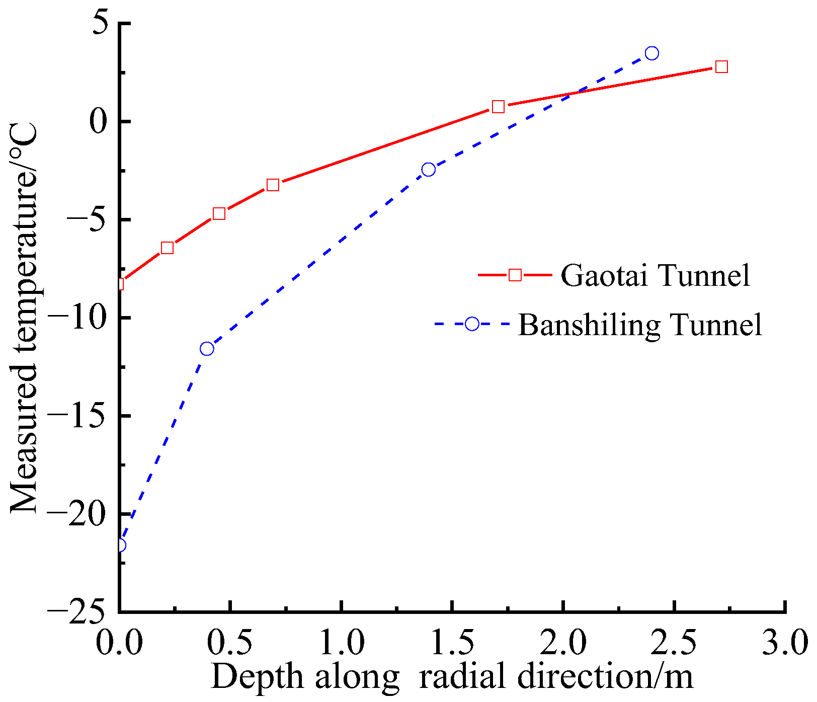
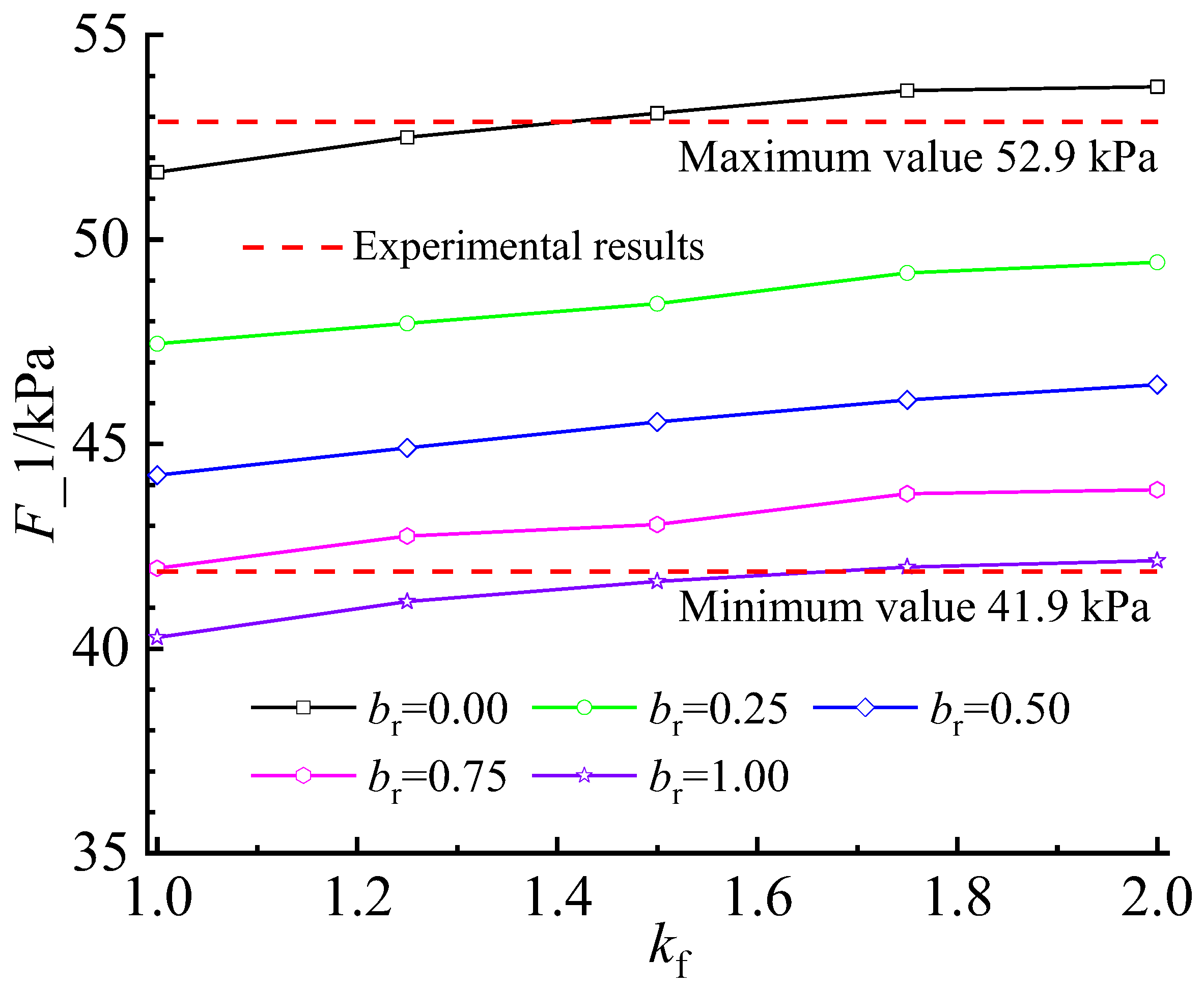
5.3. Comparison with Experimental Results

A series of indoor physical model similar experiments were carried out by Sun [31] to explore the characteristics of the frost-heaving force. For this model experiment, the surrounding rock comprised similar materials, namely barite powder, fine sand, and soil. A similar material of the support structure was gypsum. The length of the model box was 1.6 m, the width was 1.2 m, and the height was 1.095 m, as shown in Figure 7. Eight strained-pressure cells were arranged on the outer surface of the support structure, as shown in Figure 8. The inner and outer radii of the support structure were 0.08 m and 0.095 m, respectively. The similarity ratio was set to 50. The freezing depth of the rock mass was controlled using freezing equipment composed of a temperature control device, air-blower, air compressor, and thermal insulation materials. The freezing depth during the experiment was set to 0.1 m. The volumetric strain of the surrounding rock caused by frost heave (εv) was 0.0203, and the far-field pressure (P_0) was 5.369 kPa [10]. The other parameters are shown in Table 2.
The comparison results between this study and the model experiment are shown in Figure 9. Noticeably, the results obtained from this study are largely consistent with other content from the model experiment when the values of parameters br and kf are reasonable. The maximum and minimum deviations between this study and the model experiment were 1.5% and 3.9%, respectively. When br = 0.25, 0.50, and 0.75, kf increased from 1.0 to 2.0, and the analytical solution always fell within the range of the model experimental results. This further verifies the accuracy of the analytical solution in this study.

6. Analysis of Model Parameters

In this section, the control variate method [32,33] is employed to explore the influences of the main model parameters, such as the external pressure F_0, influence coefficient br, the radial gradient influence coefficient αf, and the anisotropic frost heave coefficient kf on the stress, displacement, and plastic zone radius, and frost-heaving force. The values of the model parameters used for the control variate analysis are listed in Table 1.
The stress distribution curves of the rock mass and the support structure under different model parameters are shown in Figure 10. Regarding the radial stress σr, except for the slight effect of br on σr in the plastic zone of the frozen rock mass II-1, the influences of parameters F_0, αf, and kf on σr were negligible, and the maximum deviation between different parameters was less than 2.0%. Regarding the circumferential stress σθ, the impacts of parameters F_0, br, αf, and kf on σθ were mainly reflected in support zone I and frozen rock mass zone II, and the effects in unfrozen rock mass III were likewise negligible. As F_0 increased from 0.0 MPa to 1.0 MPa, σθ increased in zones I and II-1 and decreased in zone II-2. The influence of the intensity of F_0 on σθ in zone I was greater than that in zones II-1 and II-2. As br increased from 0.0 to 1.0, σθ decreased in zone I and increased in zones II-1 and II-2. The influence of the intensity of br on σθ in zones I and II-1 was greater than that in zone II-2, especially in zone I and the elastic–plastic contact surface in zone II. As parameter αf increased from 0.0 to 0.4, σθ increased in zones I and II-1 and decreased in zone II-2. The influence of the intensity of αf on σθ in zone I was greater than that in zones II-1 and II-2. As kf increased from 1.0 to 3.0, σθ increased in zones I and II-1 and decreased in zone II-2. The influence of the intensity of parameters kf on σθ in zone II-2 was greater than that in zones I and II-1.
The effects of the model parameters on the plastic zone radius RP and the frost-heaving force F_1 are shown in Figure 11. RP decreased with the increase in F_0, br, αf, and kf. A significant negative correlation exists between RP and F_0, br, αf, and kf. For example, when br increased from 0.25 to 0.75, RP decreased from 5.86 m to 5.76 m, and the decreasing amplitude was approximately 1.7%. When αfr increased from 0.0 to 0.4, RP decreased from 5.94 m to 5.87 m, and the decrease in amplitude was approximately 1.2%. Moreover, F_1 increased with the increase in F_0, αf, and kf, and a positive correlation exists between F_1 and F_0, αf, and kf. F_1 decreased with the increase in br, and F_1 is negatively correlated with br. For example, when br increased from 0.25 to 0.75, F_0 decreased from 1.96 MPa to 1.54 MPa, and the decreasing amplitude was approximately 27.3%. When kf increased from 1.5 to 2.5, F_0 increased from 2.40 MPa to 2.50 MPa, a decrease of approximately 4.2%. In summary, after considering br, RP decreased, and the development of F_1 was suppressed. However, after considering parameters F_0, αf, and kf, RP decreased, whereas the development of the F_1 was accelerated. Therefore, during the design of tunnel structures in cold regions, parameters F_0, αf, and kf should be reasonably considered, whereas parameter br should be carefully considered.

7. Conclusions

The structural frost damage induced by the frost-heaving force is one of the main challenges in cold-region tunnels. The frost-heaving force was studied from a new perspective in this paper, and the main conclusions obtained were drawn as follows:
(1)
A dual transverse isotropic model of frozen rock mass is proposed based on strain and elastic modulus. If the values of these parameters are reasonable, the dual transverse isotropic model can be simplified as the isotropy case.
(2)
By combining unified strength theory and the non-associated flow rule, an elasto-plastic mechanical model for a high-speed railway tunnel in cold regions is established and solved by considering the dual transverse isotropy of frozen rock mass. The accuracy of the mechanical model proposed by the authors is verified by comparing it with that of existing models and the test results based on the same model parameters.
(3)
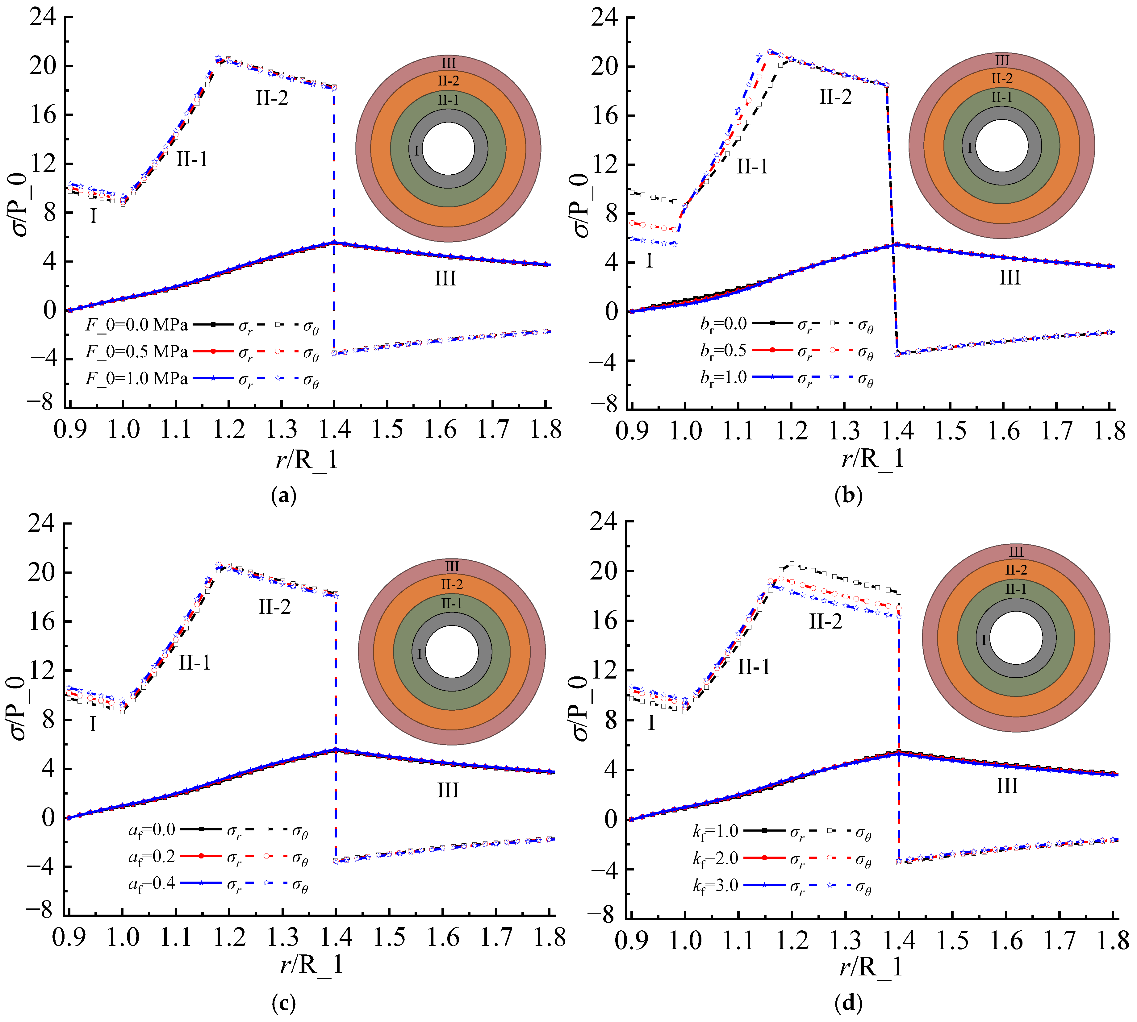
A significant negative correlation exists between RP and F_0, br, αf, and kf, as well as between F_1 and parameter br. Further, a positive correlation exists between F_1 and F_0, αf, and kf. During the design of tunnel structures in cold regions, parameters F_0, αf, and kf should be reasonably considered, whereas parameter br should be carefully considered.
(4)
The increase in elastic modulus with depth along the radial direction is assumed to be a power-law function. Other functional forms should be further explored based on on-site monitoring and experimental results.

Author Contributions

Methodology, P.Z.; Software, P.Z.; Validation, Q.F.; Resources, W.M.; Data cura-tion, P.Z.; Writing—original draft, P.Z.; Supervision, Q.F. All authors have read and agreed to the published version of the manuscript.

Funding

This research was funded by the Project of Research on Typical Frost Damage Mechanisms and Countermeasures of High-speed Rail Tunnel Structures in Northeast, China under Grant N2022G022.

Institutional Review Board Statement

Not applicable.

Informed Consent Statement

Not applicable.

Data Availability Statement

The data used to support the findings of this study are available from the corresponding author upon request.

Acknowledgments

We thank the anonymous reviewers for their constructive comments and suggestions to improve the quality of this article.

Conflicts of Interest

Author Weibin Ma was employed by the company China Academy of Railway Sciences Corporation Limited. The remaining authors declare that the research was conducted in the absence of any commercial or financial relationships that could be construed as a potential conflict of interest.

Notations

σStress
εStrain
kAnisotropic frost heave coefficients
εvVolumetric strain
EElastic modulus
rDistance from the tunnel center in the radial direction
RufDepth of the frozen rock mass
αfRadial gradient influence coefficient of the frozen rock mass
R_0Inner radius of zone I
R_1Outer radius of zone I or the inner radius of zone II
R_2Outer radius of zone II or the inner radius of zone III
RPPlastic radius of the frozen rock mass zone II
F_0Pressure acting on the inner surface of the support structure
F_1Pressure acting on the outer surface of the support structure or the frost-heaving force
FPPressure acting on the contact surface between zone II-1 and zone II-2
F_2Pressure acting on the contact surface between zone II-2 and zone III
P_0Initial ground stress in the tunnel situ
uDisplacement
μPoisson’s ratio
A BUnified strength theory parameters
brInfluence coefficient of intermediate principal stress
cCohesion
φInternal friction angle
DAn integral constant related to the boundary conditions
βCharacteristic parameters related to shear expansion
QAn integral constant related to the boundary conditions
subscripts r, θ, and lRadial, circumferential, and longitudinal directions, respectively
subscripts f and ufFrozen and unfrozen rock mass, respectively

References

  1. Lai, Y.M.; Wu, H.; Wu, Z.W.; Liu, S.Y.; Den, X.J. Analytical viscoelastic solution for frost force in cold-region tunnels. Cold Reg. Sci. Technol. 2000, 31, 227–234. [Google Scholar] [CrossRef]
  2. Zhao, P.Y.; Chen, J.X.; Luo, Y.B.; Li, Y.; Chen, L.J.; Wang, C.W.; Hu, T.T. Field measurement of air temperature in a cold region tunnel in northeast China. Cold Reg. Sci. Technol. 2020, 171, 102957. [Google Scholar] [CrossRef]
  3. Gao, G.Y.; Chen, Q.S.; Zhang, Q.S.; Chen, G.Q. Analytical elasto-plastic solution for stress and plastic zone of surrounding rock in cold region tunnels. Cold Reg. Sci. Technol. 2012, 72, 50–57. [Google Scholar] [CrossRef]
  4. Feng, Q.; Jiang, B.S.; Zhang, Q.; Wang, L.P. Analytical elasto-plastic solution for stress and deformation of surrounding rock in cold region tunnels. Cold Reg. Sci. Technol. 2014, 108, 59–68. [Google Scholar] [CrossRef]
  5. Liu, W.W.; Feng, Q.; Fu, S.G.; Wang, C.X. Elasto-plastic solution for cold-regional tunnels considering the compound effect of non-uniform frost heave, supporting strength and supporting time. Tunn. Undergr. Space Technol. 2018, 82, 293–302. [Google Scholar] [CrossRef]
  6. Xia, C.C.; Lv, Z.T.; Li, Q.; Huang, J.H.; Bai, X.Y. Transversely isotropic frost heave of saturated rock under unidirectional freezing condition and induced frost heaving force in cold region tunnels. Cold Reg. Sci. Technol. 2018, 152, 48–58. [Google Scholar] [CrossRef]
  7. Feng, Q.; Fu, S.G.; Wang, C.X.; Liu, W.W.; Wang, Y.; Qiao, W.G. Analytical elasto-plastic solution for frost force of cold-region tunnels considering anisotropic frost heave in the surrounding rock. KSCE J. Civ. Eng. 2019, 23, 3831–3842. [Google Scholar] [CrossRef]
  8. Du, J.M.; Fang, Q.; Wang, G.; Zhang, D.L.; Chen, T.L. Fatigue damage and residual life of secondary lining of high-speed railway tunnel under aerodynamic pressure wave. Tunn. Undergr. Space Technol. 2021, 111, 103851. [Google Scholar] [CrossRef]
  9. Lv, Z.T.; Yuan, S.Q.; Lin, H. Analytical stress solution for cold region tunnels with unequal ground stress and support delay under different frost heave conditions of surrounding rock. Cold Reg. Sci. Technol. 2023, 206, 103742. [Google Scholar] [CrossRef]
  10. Lv, Z.T.; Xia, C.C.; Wang, Y.S.; Luo, J. Analytical elasto-plastic solution of frost heaving force in cold region tunnels considering transversely isotropic frost heave of surrounding rock. Cold Reg. Sci. Technol. 2019, 163, 87–97. [Google Scholar] [CrossRef]
  11. Li, H.W.; Lai, Y.M.; Zhang, H.Y.; Chen, Y.Y.; Jiang, W.T.; Tian, Y.; Ran, J.C. Composite lining-ground interaction behavior in a cold-region circular tunnel under isotropic frost heave action. Cold Reg. Sci. Technol. 2023, 207, 103771. [Google Scholar] [CrossRef]
  12. Cao, S.P.; Xia, C.C.; Zhou, S.W.; Zhang, Y. Unified strength-based elastoplastic solution for frost heaving force of cold-region tunnels considering dual non-uniform frost heaving of surrounding rock. Cold Reg. Sci. Technol. 2024, 217, 104054. [Google Scholar] [CrossRef]
  13. Feng, Q.; Liu, W.W.; Jiang, B.S. Analytical solution for the stress and deformation of rock surrounding a cold-regional tunnel under unequal compression. Cold Reg. Sci. Technol. 2017, 139, 1–10. [Google Scholar] [CrossRef]
  14. Yu, Y.; Ling, X.Z.; Tang, L.; Han, X.; Geng, L.; Wei, S.W. Analytical solution for the soil-lining interaction in cold region deep tunnel considering the delayed installation of the lining. Cold Reg. Sci. Technol. 2021, 189, 103329. [Google Scholar] [CrossRef]
  15. Huang, S.B.; Liu, Q.S.; Liu, Y.Z.; Ye, Z.Y.; Cheng, A.P. Freezing strain model for estimating the unfrozen water content of saturated rock under low temperature. Int. J. Geomech. 2018, 18, 04017137. [Google Scholar] [CrossRef]
  16. Zheng, X.Y.; Xu, F.; Zhang, B.; Xu, H.B.; Gao, Y. Model test on frost heaving pressure induced by frozen partial ponding behind tunnel lining in cold region. Tunn. Undergr. Space Technol. 2024, 145, 105607. [Google Scholar] [CrossRef]
  17. Tan, X.J.; Chen, W.Z.; Yang, J.P.; Cao, J.J. Laboratory investigations on the mechanical properties degradation of granite under freeze–thaw cycles. Cold Reg. Sci. Technol. 2011, 68, 130–138. [Google Scholar] [CrossRef]
  18. Zhang, H.M.; Meng, X.Z.; Yang, G.S. A study on mechanical properties and damage model of rock subjected to freeze-thaw cycles and confining pressure. Cold Reg. Sci. Technol. 2020, 174, 103056. [Google Scholar] [CrossRef]
  19. Gu, J.F.; Li, K.; Su, L. Modified nonlinear Mohr–Coulomb fracture criteria for isotropic materials and transversely isotropic UD composites. Mech. Mater. 2020, 151, 103649. [Google Scholar] [CrossRef]
  20. Yang, W.Y.; Bai, P.P.; Fang, J.B.; Li, Y.T.; Shi, Z.Q.; Zhou, Q.H. Contact responses of transversely isotropic layered material with imperfect interface. Int. J. Mech. Sci. 2024, 272, 109145. [Google Scholar] [CrossRef]
  21. Jiang, H.Q.; Niu, F.J.; Ma, Q.G.; Jiang, W.T.; Hu, H.; Wang, E.L.; Jiao, C.L.; Li, Z.G. Thermal characteristics investigation of a high-speed railway tunnel by field monitoring in Northeast of China. Transp. Geotech. 2021, 30, 100615. [Google Scholar] [CrossRef]
  22. Du, J.M.; Fang, Q.; Wang, G.; Wang, J. Analytical solution of a circular lined tunnel with alterable mechanical property under hydrostatic stress and internal pressure. J. Cent. South Univ. 2022, 29, 2757–2770. [Google Scholar] [CrossRef]
  23. Galan, I.; Baldermann, A.; Kusterle, W.; Dietzel, M.; Mittermayr, F. Durability of shotcrete for underground support– Review and update. Constr. Build. Mater. 2019, 202, 465–493. [Google Scholar] [CrossRef]
  24. Yu, M.H. Twin shear stress yield criterion Author links open overlay panel. Int. J. Mech. Sci. 1983, 25, 71–74. [Google Scholar] [CrossRef]
  25. Wang, C.W.; Liu, X.L.; Song, D.Q.; Wang, E.Z.; Zhang, J.M. Elasto-plastic analysis of the surrounding rock mass in circular tunnel using a new numerical model based on generalized nonlinear unified strength theory. Comput. Geotech. 2023, 154, 105163. [Google Scholar] [CrossRef]
  26. Liu, X.Y.; Liu, E.L. Application of new twin-shear unified strength criterion to frozen soil Author links open overlay panel. Cold Reg. Sci. Technol. 2019, 167, 102857. [Google Scholar] [CrossRef]
  27. Hou, Y.; Min, J.Y.; Lin, J.P.; Lee, M.G. Modeling stress anisotropy, strength differential, and anisotropic hardening by coupling quadratic and stress-invariant-based yield functions under non-associated flow rule. Mech. Mater. 2022, 174, 104458. [Google Scholar] [CrossRef]
  28. Zhang, T.Y.; Han, X.H. Parameter identification for the non-associated flow rules representing corner effects through the equivalent tangential shear modulus reduction after abrupt strain-path change. Int. J. Plast. 2023, 169, 103726. [Google Scholar] [CrossRef]
  29. Wang, S.C.; Shang, H.C.; Han, M.; Zhou, C.; Chen, Q.; Lou, Y.S. Lode-dependent Yld91 function for anisotropic-asymmetric hardening modeling of metals under non-associated flow rule. J. Mater. Process. Technol. 2024, 325, 118298. [Google Scholar] [CrossRef]
  30. Du, J.M.; Zhang, X.; Wang, H.L. Elasto-plastic solution for a circular lined tunnel considering yield criteria for surrounding rock and functionally graded lining in cold-region tunnels. Sustainability 2023, 15, 11577. [Google Scholar] [CrossRef]
  31. Sun, B. Model test study of frost heaving pressures in tunnels excavated in fractured rock mass in cold regions. Sci. Cold Arid Reg. 2010, 2, 405–410. [Google Scholar]
  32. Bomarito, G.F.; Leser, P.E.; Warner, J.E.; Leser, W.P. On the optimization of approximate control variates with parametrically defined estimators. J. Comput. Phys. 2022, 451, 110882. [Google Scholar] [CrossRef]
  33. Belomestny, D.; Goldman, A.; Naumov, A.; Samsonov, S. Theoretical guarantees for neural control variates in MCMC. Math. Comput. Simul. 2024, 220, 382–405. [Google Scholar] [CrossRef]
Figure 1. Structural damage in cold-region tunnels.
Applsci 14 11796 g001
Figure 2. Schematic of transversely isotropic material.
Applsci 14 11796 g002
Figure 3. Temperature distribution along the radial direction.
Applsci 14 11796 g003
Figure 4. Schematic of rock damage caused by freeze–thaw exposure.
Applsci 14 11796 g004
Figure 5. Schematic of mechanical model of cold-region tunnel.
Applsci 14 11796 g005
Figure 6. Comparison results between proposed and existing models [4,10].
Applsci 14 11796 g006
Figure 7. Model box.
Applsci 14 11796 g007
Figure 8. Layout of strained-pressure cells.
Applsci 14 11796 g008
Figure 9. Comparison between this study and model experiment.
Applsci 14 11796 g009
Figure 10. Stress distribution under different model parameters: (a) pressure acting on inner surface of support F_0; (b) influence coefficient of intermediate principal stress br; (c) radial gradient influence coefficient αf; (d) anisotropic frost heave coefficient kf.
Applsci 14 11796 g010
Figure 11. Influence of model parameters on plastic zone radius RP and frost-heaving force F_1: (a) pressure acting on inner surface of support F_0; (b) influence coefficient of intermediate principal stress br; (c) radial gradient influence coefficient αf; (d) anisotropic frost heave coefficient kf.
Applsci 14 11796 g011
Table 1. Model parameters based on the Yuximolegai tunnel.
ZoneElastic Modulus/GPaPoisson’s RatioCohesion/MPaInternal Friction Angle/°
Support zone28.00.16//
Frozen rock mass zone7.80.351.745
Unfrozen rock mass zone4.60.33//
Table 2. Experimental parameters.
ZoneElastic Modulus/MPaPoisson’s RatioCohesion/kPaInternal Friction Angle/°
Support zone615.00.205//
Frozen rock mass zone74.00.414.531.2
Unfrozen rock mass zone37.00.413.024.0
Disclaimer/Publisher’s Note: The statements, opinions and data contained in all publications are solely those of the individual author(s) and contributor(s) and not of MDPI and/or the editor(s). MDPI and/or the editor(s) disclaim responsibility for any injury to people or property resulting from any ideas, methods, instructions or products referred to in the content.

